

Page 1

EW-F & EK Series
Electronic Metering Pump
Instruction Manual
W A L C H E M
EW-F & EK Series Metering Pumps
Five Boynton Road Hopping Brook Park Holliston, MA 01746 USA
IWAKI America Inc.
TEL: 508-429-1110 FAX: 508-429-7433 WEB: www.walchem.com
Page 2

Notice
© 2014 WALCHEM, Iwaki America Inc. (hereinafter “Walchem”)
Five Boynton Road, Holliston, MA 01746 USA
tel (508) 429-1110 fax (508) 429-7433
All Rights Reserved
Printed in USA
Proprietary Material
The information and descriptions contained herein are the property of WALCHEM. Such
information and descriptions may not be copied or reproduced by any means, or disseminated or
distributed without the express prior written permission of WALCHEM.
This document is for information purposes only and is subject to change without notice.
Statement of Limited Warr a nty
WALCHEM warrants equipment of its manufacture and bearing its identification to be free from
defects in workmanship and material for a period of two years from date of delivery from the
factory or authorized distributor under normal use and service and otherwise when such equipment
is used in accordance with instructions furnished by WALCHEM and for the purposes disclosed in
writing at the time purchased, if any. WALCHEM’s liability under this warranty shall be limited to
replacement or repair, F.O.B. Holliston, MA U.S.A. of any defective equipment or part which,
having been returned to WALCHEM, transportation charges prepaid, has been inspected and
determined by WALCHEM to be defective.
THIS WARRANTY IS IN LIEU OF ANY OTHER WARRANTY, EITHER EXPRESS OR IMPLIED,
AS TO DESCRIPTION, QUALITY, MERCHANT-ABILITY, FITNESS FOR ANY PARTICULAR
PURPOSE OR USE, OR ANY OTHER MATTER.
P/N E00118.P
Sept 2014
Page 3

TABLE OF CONTENTS
Thank you for choosing a Walchem E-Class metering pump. This instruction manual deals with the
correct installation, operation, maintenance and troubleshooting procedures for the EW and EK model
metering pumps. Please read through it carefully to ensure the optimum performance, safety and service
of your pump.
1.0 INTRODUCTION ........................................................................................................... 1
1.1 Safety and Caution Notes .......................................................................................... 1
1.2 Principle of Operation ................................................................................................ 1
1.3 Model Code ............................................................................................................... 2
1.4 Specifications ............................................................................................................ 3
1.5 Dimensions ................................................................................................................ 4
2.0 INSTALLATION ............................................................................................................ 7
2.1 Unpacking ................................................................................................................. 7
2.2 Location ..................................................................................................................... 7
2.3 Supply Tubing............................................................................................................ 8
2.4 Discharge Tubing ...................................................................................................... 9
2.5 Installing Injection/BackPressure Valve ................................................................... 10
2.6 Electrical .................................................................................................................. 10
3.0 OPERATION ............................................................................................................... 11
3.1 Pump Operation & Programming ............................................................................. 11
3.2 External Inputs & Outputs ........................................................................................ 13
3.3 Adjustment .............................................................................................................. 16
3.4 MultiFunction Valve Operation ................................................................................. 17
3.5 Auto Air Vent Valve Operation ................................................................................. 18
3.6 Priming .................................................................................................................... 18
3.7 Calibration ............................................................................................................... 19
3.8 AC Power Interruption ............................................................................................. 19
4.0 MAINTENANCE .......................................................................................................... 20
4.1 Diaphragm Replacement ......................................................................................... 20
4.2 Valve Replacement ................................................................................................. 20
4.3 Tubing ..................................................................................................................... 20
5.0 EXPLODED VIEW & PARTS GUIDE .......................................................................... 21
6.0 TROUBLESHOOTING ................................................................................................ 32
7.0 SERVICE POLICY ...................................................................................................... 32
Page 4
1
1.0 INTRODUCTION
1.1 Safety and Caution Notes
Always wear protective clothing, eye protection and gloves before working on or near a
metering pump. Follow all recommendations of the supplier of the solution being pumped.
Refer to the MSDS from the solution supplier for additional precautions.
Walchem E-Class metering pumps should be installed where ambient temperatures do not
exceed 122°F (50°C) or do not fall below 32°F (0°C). Pumps should always be shielded from
direct exposure to the elements. Black UV resistant tubing should be used if the tubing is
exposed to strong UV radiation (sunlight/lamps). The EK Series is specifically designed to
withstand the elements and can be mounted directly outdoors within the temperature
specfications. To protect and maintain the IP rating of the pump, the clear covers that protect
the electronic controls MUST be left in a secured/tightened condition at all times other than
during adjustment of the pump.
WARNING Risk of electrical shock! This pump is supplied with a grounding conductor
and grounding-type attachment plug. To reduce the risk of electrical shock, be certain that it is
connected only to a properly grounded, grounding type receptacle with ratings conforming to the
data on the pump data plate. Prior to performing any maintenance on a pump, disconnect the
pump from the electrical power source.
Plumbing Precautions
All tubing must be securely attached to the fittings prior to starting the pump (see Section 2.3).
Only use Walchem tubing with your pump. Tubing should be shielded to prevent possible
injury in case of rupture or damage. UV resistant tubing should be used if the tubing is exposed
to UV light. Always adhere to local plumbing codes and requirements. Be sure that the
installation does not constitute a cross connection. Walchem is not responsible for improper
installations. Prior to performing any maintenance on a pump, depressurize the discharge
tubing.
If you are pumping downhill or into little or no system pressure, a back pressure/anti-syphon
device must be installed to prevent over-pumping. Contact your Walchem distributor for
additional information.
Solution Compatibility
CAUTION! This pump has been evaluated for use wit h water only. The suitability of this
pump for use with liquids other than water, such as acid and alkaline, is the responsibility of the
user. For liquids other than water, select the best-suited liquid end material combination using a
chemical com p atib il ity chart.
1.2 Principle of Operation
The E-Class electronic metering pumps consist of a pump unit, a drive unit, and a control unit.
The drive unit is an electromagnetic solenoid. When the solenoid coil is energized by the
control unit the armature shaft moves forward due to the magnetic force of the solenoid. The
shaft is attached to a PTFE faced diaphragm which is part of the pump unit. The diaphragm is
forced into the pump head cavity decreasing volume and increasing pressure which forces liquid
in the pump head out through the discharge check valves. When the solenoid coil is deenergized, a spring returns the armature to its starting position. This action pulls the diaphragm
out of the head cavity increasing volume and decreasing pressure. Atmospheric pressure then
pushes liquid from the supply tank through the suction check valves to refill the pump head.
Page 5

2
1.3 Model Code
EW B16 F 1 - VC A
1 2 3 4 5 6
1 Pump Series
EW IP 65 electronic metering pump with external pulse control or manual
speed control (adjustable to 360 strokes per minute) and manually
adjustable stroke length. (Turndown ratio 1800:1.)
EK IP 67 aggressive environment rated electronic metering pump with
external pulse control or manual speed control (adjustable to 360
strokes per minute) and manually adjustable stroke length. (Turndown
ratio 1800:1.)
2
Capacity/Pressure Rating (See Section 1.4 for detailed chart.)
3 Control Module
F
For use on all EW models, features digitally adjustable speed and
external pulse input control, stop & pre-stop inputs
R For use on all EK models, features external pulse input control and stop
input.
4 Voltage
1 115 VAC, 50/60 Hz
2 230 VAC, 50/60 Hz
5 Liquid End (See Section 1.4 for detailed chart.)
6 Options
A Auto Air Vent Valve is supplied in place of the manual air vent valve.
Available for B11, B16, C16 and C21 sizes with -VC liquid ends only.
M Multifunction Valve is supplied in place of the manual air vent valve.
Available for the EW and EK 11-21 sized pumps with VC, VE, VF, PC,
and PE liquid ends. Not available with the AAVV feature.
H High Pressure pump configuration available with EW–PC and –PE
liquid ends only. High Pressure pump maximum speed is 240 SPM.
Page 6
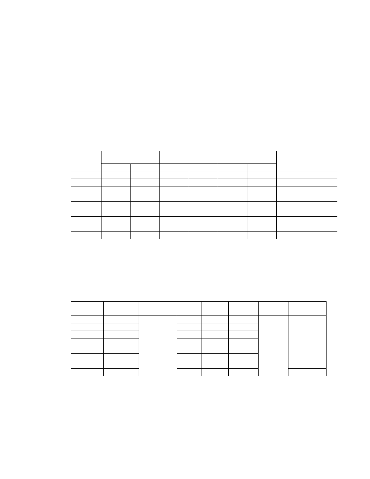
3
Size
Maximum
Output Capacity
Output
per Stroke (mL)
Maximum
Pressure1
Tubing O.D
(Gal/hr)
(mL/min)
Min.
Max.
PSI
MPa
B11
0.6
38
0.03
0.11
150
1.0
3/8
B16
1.0
65
0.04
0.18
105
0.7
3/8
B21
1.8
115
0.07
0.32
60
0.4
3/8
B31
3.3
210
0.12
0.58
30
0.2
1/2
C16
1.3
80
0.05
0.22
150
1.0
3/8
C16-H
0.6
40
0.03
0.17
250
1.7
⅜ (suc) x ¼ NPT (dis)
C21
2.3
145
0.08
0.40
105
0.7
3/8
C31
4.3
270
0.15
0.75
50
0.35
1/2
C362
6.7
420
0.24
1.17
30
0.2
1/2
Liquid End
Code
Pump Head
& Fittings
Diaphragm
Valve
Balls
Valve
Seat
Valve
Seals
Gasket
Tubing
PC
GFRPP
CE
FKM
FKM
PE
GFRPP
CE
EPDM
EPDM
VC
PVC
CE
FKM
FKM
VE
PVC
CE
EPDM
EPDM
VF
PVC
PTFE
EPDM
EPDM
TC
PVDF
CE
FKM
FKM
FC
PVDF
CE
PCTFE
PTFE
SH
SS
HC
HC
PTFE
¼” NPTF
1.4 Specifications
Electrical 50/60 Hz, single phase
EWB/EKB 115 VAC±10% 0.8 Amp max. 20 watt avg.
230 VAC±10% 0.4 Amp max. 20 watt avg.
EWC/EKC 115 VAC±10% 1.2 Amp max. 22 watt avg.
230 VAC±10% 0.6 Amp max. 22 watt avg.
Operating Conditions
Ambient temperature 32°F to 122°F (0°C to 50°C)
Relative humidity To 85% (EW) / 95% (EK) non-condensing
Liquid temperature 32° to 104°F (0 to 40°C) for PVC based liquid ends
32° to 140°F (0 to 60°C) for PP, PVDF, SS based liquid ends
Below 32°F (0°C), pump is limited to 70% of max. pressure. Liquid cannot freeze.
Capacity/Pressure Rating
Connection
Size (in)
1
Auto Air vent valve reduces maximum pressure approx. 35 PSI (0.2 MPa)
2
Output of the EW/EKC36-TC/FC/SH is 6.3 GPH (400 ml/min)
Adjustment Range
Stroke length adjustment range 20% to 100%
Frequency adjustment range 0 to 360 strokes per minute
Materials of Construction
PTFE
(bonded to
EPDM)
PTFE
CE Alumina ceramic PE Polyethylene
EPDM Ethylene propylene diene monomer PTFE Polytetrafluoroethylene
FKM Fluoroelastomer PVC Polyvinylchloride ( translucent)
GFRPP Glass fiber reinforced polypropylene PVDF Polyvinylidenefluoride
HC Hastelloy C276 SS 316 stainless steel
PCTFE Polychlorotrifluoroethylene
PE
Page 7
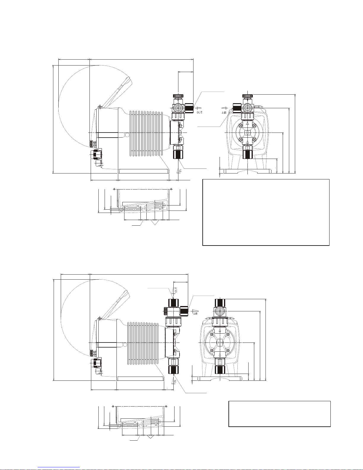
4
EW-31 and 36 Models with thermoplastic liquid ends
Notes:
(10.14”)(3.02”)
1.50”
(10.45”)
(2.65”)
4.92”
(0.96”)
4.17”
3.15”
0.59”
0.79”
0.59”
1.57”
4.57”
3.94”
0.24”
ø3/8” X ø1/2”
TUBING (ID x OD)
TUBING (ID x OD)
TUBING (ID x OD)
ø3/8” X ø1/2”
ø3/8” X ø1/2”
(7.17”)
(8.43”)
3.94”
(0.70”)
0.39”
Notes:
4.92”
4.57”
3.94”
0.24”
3.15”
4.17”
0.59”
0.79”
0.59”
1.5
7”
ø1/4” x ø3/8”
ø1/4” x ø3/8”
TUBING (ID X OD)
TUBING (ID X OD)
TUBING (ID X OD)
ø1/4” x ø3/8”
(1.46”)
(10.02”)
(3.02”)
(10.45”)
(2.65”)
(0.89”)
0.39”
(1.42”)
3.94”
(6.30”)
(7.64”)
(See Note 1)
(See Note 1)
(See Note 2)
(See Note 3)
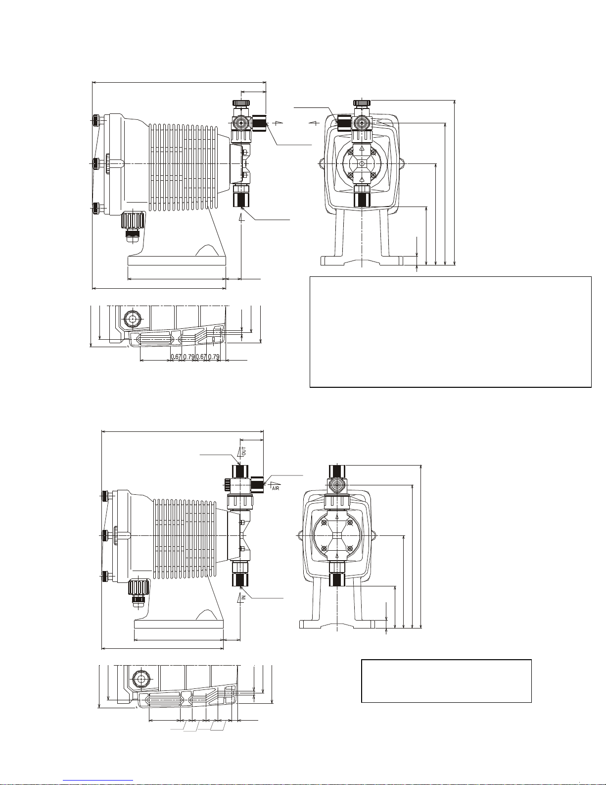
1.5 Dimensions
EW-11,16 and 21 Models with thermoplastic liquid end materials
1. Addition of a Multifunct ion valve increases overal l
length by 0.37”. Addition of an Auto Air Vent Valve
increases overall length by 1.59”
2. Addition of a Multifunction Valve increases discharge
height by 0.22”. No change for the Auto Air Vent Valve.
3. Addition of a Multifunction Valve increases overall
liquid end height by 1.16”. No change for the Auto Air
Vent Valve.
4. All dimensions in inches.
1. All dimensions in inches.
Page 8
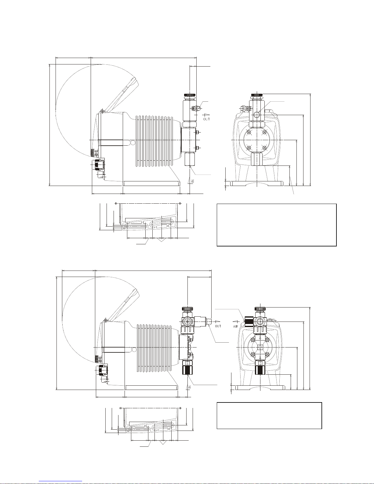
5
(3.02”) (10.77”)
(2.20”)
(10.45”)
(2.65”)
4.92”
(0.89”)
TUBING (ID x OD)
ø1/4” x ø3/8”
TUBING (ID x OD)
ø1/4” x ø3/8”
THREAD
1/4” NPT
(7.64”)
(6.30”)
3.94”
(1.42”)
0.39”
4.57”
3.94”
0.24”
1.57”
0.59”
0.59”
0.79”
3.15”
4.17”
Notes:
Notes:
(9.15”)
(3.02”)
(0.59”)
(10.45”)
4.92”
(2.65”)
(0.85”)
ø4
OD
NPT 1/4”
0.39”
(1.73”)
3.94”
(6.10”)
(7.91”)
NPT 1/4”
4.17”
3.15”
1.57”
0.59”
0.79”
0.59”
4.57”
3.94”
0.24”
(See Note 2)
(See Note 3)
(See Note 4)
(See Note 5)
EW-SH Models (EWB11,21/C21 shown below. See notes for changes in dimensions with other sizes)
1. All dimensions in inches.
2. (0.91”) for EWC31 and 36 sizes.
3. (1.34”) for EWC31 and (1. 24”) for EWC36.
4. (6.57”) for EWC31 and (6. 67”) for EWC36.
5. (8.34”) for EWC31 and (8. 48”) for EWC36.
EW-HP Models
1. All dimensions in inches.
Page 9
6
Notes:
Notes:
(SEE NOTE 1)
(SEE NOTE 1)
(SEE NOTE 3)
(SEE NOTE 2)
10.14"
1.46"
9.61"
8.27"
5.91"
3.39"
0.51"
0.91"
5.71"
7.78"
4.80"
3.94"
0.24"
3.15"
4.33"
0.31"
1.77"
ø1/4" x ø3/8"
ø1/4" x ø3/8"
ø1/4" x ø3/8"
IN
OUT
AIR
10.33"
1.50"
ø3/8"
x ø1/2"
ø3/8" x ø1/2"
ø3/8" x ø1/2"
5.71"
1.06"
7.78"
0.51"
2.68"
5.91"
9.14"
10.40"
4.80"
3.94"
1.77"
0.67"
0.79"
0.67"
0.79"
0.31"
0.24"
3.15"
4.33"
EK-11,16 ands 21 Models with the r moplastic liqui d en d ma ter ials
EK-31 and 36
Models with thermoplastic liquid ends
1. Addition of a Multifunct ion valve increases overal l
length by 0.37”. Addition of an Auto Air Vent Valve increases overall length
by 1.59”
2. Addition of a Multifunct ion Valve increases discharge height by 0.22”. No
change for the Auto Air Ven t Valve.
3. Addition of a Multifunction Valve increases overall liquid end height by 1.16”.
No change for the Auto Air Vent Valve.
4. All dimensions in inches.
1. All dimensions in inches.
Page 10
7
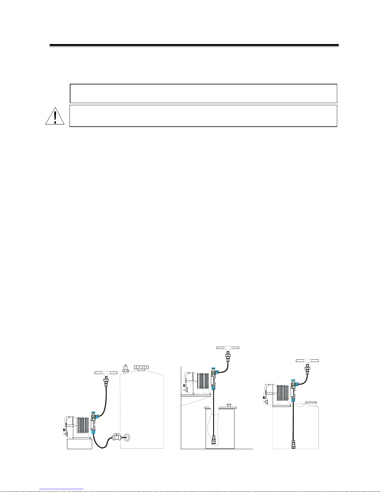
Figure 3
Figure 2
Figure 1
2.0 INSTALLATION
2.1 Unpacking
Open the shipping carton and inspect contents for damage. If any items are missing or damaged
contact your local distributor.
Pumps are pre-primed with water at the factory. If the application is not compatible with water,
drain and dry before use. Be sure to remove caps from fittings before attaching tubing.
CAUTION: Head bolts may have loosened during storage or shipment. Be sure to check and
tighten to 19 lb-in torque, if necessary.
2.2 Location
Choose a location for the pump which is clean, dry, vibration-free, close to an electrical outlet,
and allows convenient access to stroke length control, frequency control, and tubing
connections. Avoid areas where ambient temperature exceeds 122°F (50°C) or falls below 32°F
(0°C). Pumps should always be shielded from direct exposure to the elements. Black UV
resistant tubing should be used if the tubing is exposed to strong UV radiation (sunlight/lamps).
The EK Series is specifically designed to withstand the elements and can be mounted directly
outdoors with in th e temperature spe c if ications.
This pump is cord connected and not intended for permanent mounting to a building structure.
However, temporary mounting to stabilize the pump during operation may be necessary as long
as tools are not required for the installation or removal of the pump.
Flooded suction (mounting the pump below the level of liquid in the supply tank) is strongly
recommended, especially when pumping liquids that readily generate gas bubbles. Sodium
hypochlorite and hydrogen peroxide are common examples of such liquids. (See Figure 1.)
If flooded suction mounting is not possible, a shelf adjacent to (but not directly above) the
supply tank often works well. (See Figure 2.) The supply tank or cover can also be used if it
has provisions for mounting a pump. (See Figure 3.) In any case, the total suction lift should
not exceed 5 ft (1.5m).
Flooded Suction
Recommended for
liquids that out-gas
Shelf Mount
Tank Mount
Page 11
8
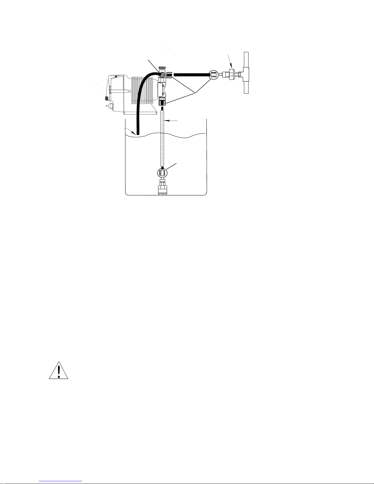
Figure 4
Foot
PVC Pipe Tubing
(user
Air Gap
Return
Point of
Injection
Injection
Valve
Coupling
Coupling Nut
(Air Vent
Coupling
2.3 Supply Tubing
The supply tubing run should be as short as possible. For flooded suction mounting, install a
shut-off valve with an appropriate tubing connector at the tank outlet. Cut a length of tubing
from the coil supplied and install between the shut-off valve and the pump inlet fitting. For
suction lift applications, slide on the ceramic weight, then install a foot valve on one end of
suction tubing. Cut the tubing to a length such that the foot valve hangs vertically about 1 in
(25mm) above the bottom of the tank. Avoid any loops in the tubing run that could form a
vapor trap. Running the tubing through a length of pipe will help to keep tubing straight. Total
vertical suction lift should be no more than 5ft. (1.5m). Reference Figure 4.
Attach tubing as shown in Figure 5. First slide the coupling nut, small end first, onto the tubing.
Push the tubing over the valve housing tip all the way to the valve housing shoulder. (Tip: if th e
tubing is stiff from cold, dip the tubing end in hot tap water for a few minutes so it will slide on
and flare out more easily. Push the coupling nut onto the threads. Apply some pressure on the
coupling nut and tubing while tightening the nut, making sure the tubing has not backed off of
the shoulder of the valve housing.
WARNING: All fittings and coupling nuts should be tightened by hand only. If necessary, a
small tool may be used to make it snug. DO NOT use excessive force or large wrenches.
The coupling nut should not bottom out completely against the fitting. If this happens during
connection, either the tubing has slid down the shoulder while tightening, or the tubing has been
pinched. Remove the coupling nut, re-cut the tubing and re-connect.
Connecting Tubing
Page 12

9
Valve
Housing
Shoulder
Coupling Nut
Tubing
Figure 6
Figure 5
"AIR"
"OUT"
Drains back to tank
Discharges to injection point
WARNING: If there is any leakage around the coupling nut and it appears to have been
installed correctly, DO NOT TIGHTEN the coupling further! Release pressure in the line,
disconnect tubing, re-cut and re-connect. Tightening of misinstalled tubing may cause the
tubing to pop off under pressure.
2.4 Discharge Tubing
Cut a length of tubing long enough to go from the pump to the application (injection) point.
Additional tubing can be ordered from your distributor. Avoid sharp turns or bends and hot
surfaces. Routing tubing through rigid pipe such as PVC pipe is recommended for long runs
and/or as protective shielding against corrosive chemicals. If applicable, install the injection
valve in 1/2” NPT thread at the injection point (see section 2.5) and connect the discharge tubing
to the injection valve.
Attach tubing as described in section 2.3 and as shown in Figures 5 and 6. Note: Some models
have an air vent valve with two outlet connections. The connection marked ‘OUT’ is the
discharge side to the application point. (Fig 6).
Attach a second length of tubing to the air vent side marked (‘AIR’) and route back to the
chemical solution tank or drum. On the larger pumps (31 & 36 sizes), the air vent valve
connections are not marked, however, the discharge side is the vertical (UP) connection and the
air vent connection is on the side of the valve.
Attaching the Tubing
Air Vent Valve Tubing
Page 13

10
Figure 7
Trim back as needed
to fit tee or fitting
Injection/Back Pressure Valve
2.5 Installing Injection/BackPressure Valve
A fitting or tee with 3/8” or 1/2” NPTF threads and with sufficient depth will accept the
injection valve assembly. If required, trim off an amount of the extension tip until it fits into the
fitting or tee. (Fig. 7.)
The position of the injection/back pressure valve can be at any orientation as long as the spring
is retained in the valve. DO NOT REMOVE THE SPRING. Be sure to check and replace the
spring as needed. Attach the tubing following the same instructions in section 2.3, connecting
the supply tubing.
CAUTION: Some chemicals may have reactions as they are injected into the main flow. For
example, sulfuric acid may react with water causing excess heat. If the chemical is heavier than
water, mount the injection valve as close as possible to vertical coming into the bottom of the
pipe. This will keep the injection nozzle facing up and keep the heavier chemistry from draining
into the pipe and causing adverse reactions within the injection valve and pipe.
In addition to preventing backflow from pressurized lines, the injection valve acts somewhat as a
back pressure valve when pumping into open atmosphere type applications. However, the back
pressure by the injection valve is very low and can vary. The output of the metering pumps is
rated at maximum back pressure and will increase as back pressure decreases dependent on the
specific installation. Additionally, the valve does NOT act as an anti-siphon valve. If siphoning
is a possibility, or if pumping downhill into open atmosphere (open tank), a Walchem
MultiFunction valve or a separate back pressure/anti-siphon valve must be installed.
Note: Siphoning can also occur at the tip of the injection valve because of the high flow rate in
the main pipe flowing past the small injection nozzle (venturi effect). In this case, an antisiphon device must be installed to avoid over feeding or siphoning of chemistry.
2.6 Electrical
WARNING Risk of electrical shock! This pump is supplied with a grounding conductor
and grounding-type attachment plug. To reduce the risk of electrical shock, be certain that it is
connected only to a properly grounded, grounding type receptacle.
CAUTION! The electronics within the pump can be damaged by excessive surges in voltage.
Do not install the pump near high-power electrical equipment that generate high surge voltages.
Avoid branch circuits that also supply power to heavy or other equipment that could generate
electrical interference. If necessary, install a surge suppression device (such as a varistor with a
resistance greater than 2000A) or a noise reducing transformer at the pump’s power connection.
Injection Valve
Page 14

11
360
Power ON
EXT
360
T-5
Set mode
+
+
UP stroke rate
DOWN stroke rate
EXT operation display
Operating at
max spm while
both keys are
pressed.
MANUAL operation display
UP stroke rate
DOWN stroke rate
Setting display
MOVES
to next
menu
SCROLL
thu choices
DISPLAY
UP Key
DOWN Key
3 6 0
ON
STOP
STOP/START Key
ON LED
STOP LED
3.0 OPERATION
3.1 Pump Operation & Programming
The EW an EK pumps have a digital display, two LED indicators and three pushbutton keys to
change the pump speed and programming.
Manually stops and starts the
pump. Used with Up/Down
keys for programming and
mode selection.
Indicates AC power to the
pump and goes off and on
with each pump stroke.
A. Operation Overview
Operating condition and
programming is displayed
ORANGE when Pre-Stop signal
is input (EW only). RED when
a START/STOP signal is input
Increases numeric values.
Used with Start/Stop key to
change the programs.
Decreases numeric values.
Used with Start/Stop key to
set the pump to operate in
EXT mode.
Page 15

12
3 6 0
Initial
Power U p
WAIT MODE
Increases Stroke Rate
Decreases Stroke Rate
Stop/Start
MANUAL RUN MODE
Increases Stroke Rate
Decreases Stroke Rate
Goes back to WAIT Mode
Stop/Start
EXTERNAL MODE
Holding the UP and DOWN
Down
+
Goes back to WAIT Mode
Stop/Start
PROGRAM MODE
Scrolls through the choices in the
Up
Goes back to WAIT Mode
Enters choic e and moves to next
3 5 2
EXT
+
B. Programming
Pressing the stop/start and up keys simultaneously will enter the program mode. The up and
down keys scroll through the menus and choices and the stop/start key will exit back to the wait
mode.
On-Time Menu
The first item displayed will be the factory set choice of the External Input On-Time menu (T-
5). There are three choices in this menu: T-5, T-20, and T-50 that can be scrolled through by
repeatedly pressing the up key. These settings are time in milliseconds and correlate to the
required minimum closure time of the external input signal for the pump to recognize it as a true
signal. Selecting the smaller T-5 (5 msec) will allow shorter duration pulses to be recognized
(typical for Hall Effect input), while the T-50 (50 msec) setting will help to reduce erroneous
pulses from noise (as from a reed switch).
Stop Input NO/NC Selection
Pressing the down key will move from the Eternal Input On-Time menu to the Stop menu and
the initial factory setting is M-OF (input is normally open and contact closure will stop the
pump). Pressing the up key will toggle between M-OF and M-ON. Setting the pump to M-ON
means that the pump will be stopped continuously and a contact closure into the stop/start input
will now start the pump and the pump will run as long as the contact is made.
Pressing the down key will again move back to the On-Time menu and pressing the stop/start
key will go back to the wait mode.
together in EXT mode will
override external and manually run
the pump at 360 SPM (priming).
Menu selection
T- 5
Menu selection
Page 16

13
Figure 9
CONNECTOR 1:
CONNECTOR 2:
1 3 4
2
1
5 3 4
2
Connector 1
Connector 2
*Note: The center pin i s marked as ‘5’ for
number ‘5’.
C. Pump Operation
Manual and On/Off Control
The pumps can be operated manually by pressing the stop/start key from the wait mode. Once
pressed, the pump will begin to operate at the stroke rate shown on the display. From here, the
up and down keys can be used to change the stroke rate, and the stroke length knob can be
adjusted down to further reduce the pump output.
Once adjusted/calibrated to the desired flow rate, the pump can be left in manual mode for
on/off control via power (connecting/disconnecting AC power from an external source) or for
on/off control via the stop/start input. Pressing the stop/start key will go back to the wait mode.
External Control
Pressing the stop/start key and the down key simultaneously from the wait mode will set the
pump to operate in external mode. In this mode, the pump will operate at a speed correlating to
the frequency of digital inputs that it receives (see section 3.2 for wiring inputs). If used, the
stop/start input will override the digital input signals.
If at any time in external mode the up and down keys are held down simultaneously, the pump
will manually run at 360 SPM as long as the two keys are held down. This feature is useful for
priming or the elimination of air trapped in the pump or tubing.
Pressing the stop/start key will disable external control and go back to the wait mode.
3.2 External Inputs & Outputs
The EW and EK pumps are capable of being controlled by an external pulse proportional input
as well as being controlled by an external stop/start signal. Additionally, the EW pumps have
two contact closure relay outputs – one output is ynchronous with the pump frequency and the
other is tied to the external stop/start signal.
A. EW Pumps and the ‘F’ control module
Two circular mini-DIN female connecto rs are used to m ak e these connect ions. Figu re 9 shows
the mating connections on the back of the pump. Connector 1 is a 5-PIN standard-key connector
(P/N E90495) and Connector 2 is a 4-PIN reverse-key connector (P/N E90494).
PIN FUNCTION
1 Voltage In (24VDC max)
2 External Digital Input
3 Out 2 (Synchronous wit h stroke)
4 Out 1 (Stop output)
5* Common
PIN FUNCTION
1 Stop/Start Input
2 Pre-St o p Input
3 Not Used
4 Common
easy identification purposes t hroughout the
manual. Actual marking on the part may
be any capital letter ( mold cavity ID) or the
Page 17

14
1
53 2
1 3 4
2
STOP I nput
Pre-STOP
Stop/
Contact
1
53 2
Sync
OR
EW
External Control
The external pulse input should not exceed 360 pulses per minute (6Hz)
and the pump will output one stroke for every input pulse. The control
signal can be a contact closure type switch (reed) with a max load of 1mA
or a solid state device. If a solid state device is used, the external circuit
should be capable of switching 5VDC at 1.2mA with an active duty cycle
pulse width of 5ms to 100ms (actual closure time).
To connect the pulse input from an external device, wire PINs 2 and 5
from the contact closure. If using a solid state switching device, wire the
connector ensuring that PIN 2 is positive (+) and PIN 5 is Common (-).
Stop/Start and Pre-Stop Control
The EW pumps have two stop inputs. The Pre-Stop is an external input
Input
that changes the green STOP LED to orange to signal a “LOW” condition.
This input does not control the pump. An external Stop/Start signal,
however, not only turns the STOP LED to red, but also controls the pump.
In this mode, AC power is applied continuously, but the pump operation is
stopped (or started – see section on programming) by completing the
circuit between PIN 1 and PIN 4 in Connector 2. Both the Pre-Stop and
Stop/Start signals can be a contact closure type switch (reed) with a max
load of 1mA or a solid state device. If a solid state device is used, the
external circuit should be capable of switching 5VDC at 1.2mA with an
active duty cycle pulse width of 5ms to 100ms (actual closure time).
To connect the Pre-Stop input from an external device, wire PINs 2 and 4 from the contact
closure. If using a solid state switching device, wire the connector ensuring that PIN 2 is
positive (+) and PIN 4 is Common (-).
To connect the Stop/Start input from an external device, wire PINs 1 and 4 from the contact
closure. If using a solid state switching device, wire the connector ensuring that PIN 1 is
positive (+) and PIN 4 is Common (-).
Output Relays
The EW pumps have two output relays (non-isolated PNP
transistors with a 330Ω resistance) in Connector 1. Output 1 is
tied to the Stop/Start input and will activate when a Stop/Start
input connection is made. Output 2 activates synchronously
with the pump stroke rate.
Contact Closure Type Outputs
The EW circuit can make either the Stop/Start (Out 1) or the
synchronous pulse (Out 2) function as contact closures, but
ONLY ONE output can be used at a time. To use the
synchronous pulse out, connect the positive side to PIN 1 and
the negative side to PINS 3&5 (jumped together). To use the
start/stop output, connect the positive side to PIN 1 and the
negative side to PINS 4&5 (jumped together).
Closu r e Input
Connector 1
Pulse
Input
Start
Input
Page 18

15
Connector
Lock Nut
Connector
Gasket &
Cord Nut
4
5 6 +
+
Connector
PIN FUNCTION
Orientation
+
4
5
6
Connector
Digital
Stop/
Volta ge type
1
53 2
Sync
Power
PLC
EW
Voltage Input Type Outputs (Non-Contact Closure)
PIN 1 will take a voltage in from an external source (max
24VDC). When this external voltage is present, then both
relays will independently switch the input voltage. Both
outputs can be used simultaneously. The figure to the left
shows a schematic with the output relays configured to
switch the powered input. This setup can only be used with
voltage input type circuits (not contact closure types) such as
those commonly found in a PLC.
B. EK Pumps and the ‘R’ control module
One custom watertight connector is used for the digital input and stop/start connections on the
EK pumps. There are no outputs on the EK pumps. The Connector Holder is keyed to fit into
the pump only one direction. There is a set of painted alignment marks on the connector and
connector holder that identify the correct orientation of the connector. Be sure to double check
that the connector is installed properly into the connector assembly before installation onto the
pump.
Input
Connector 1
OUT
Pulse
Input
Start
Input
Marks
4 External Digital Input
5 Stop/Start Input
6 Common
Holder
Adapter
Digital Control
The external pulse input should not exceed 360 pulses per minute (6Hz)
and the pump will output one stroke for every input pulse. The control
signal can be a contact closure type switch (reed) with a max load of 1mA
or a solid state device. If a solid state device is used, the external circuit
should be capable of switching 5VDC at 1.2mA with an active duty cycle
pulse width of 5ms to 100ms (actual closure time).
To connect the pulse input from an external device, wire Terminal 4 and
Input
Terminal 6 from the contact closure. If using a solid state switching
device, wire the connector ensuring that Terminal 4 is positive (+) and
Terminal 6 is Common (-).
Page 19

16
+
4
5
6
Connector
Stop/Start
Stop/Start Control
An external Stop/Start signal will turn the STOP LED to red and also
control the pump. In this mode, AC power is applied continuously, but
the pump operation is stopped (or started – see section on
programming) by completing the circuit between Terminal 5 and
Terminal 6. The Stop/Start signal can be a contact closure type switch
(reed) with a max load of 1mA or a solid state device. If a solid state
device is used, the external circuit should be capable of switching
5VDC at 1.2mA with an active duty cycle pulse width of 5ms to 100ms
(actual closu re time).
To connect the Stop/Start input from an external device, wire Terminals 5
and 6 from the contact closure. If using a solid state switching device, wire
the connections ensuring that Terminal 5 is positive (+) and Terminal 6 is Common (-).
3.3 Adjustment
A. EW Pumps using the ‘F’ Control Module
The pump will operate best keeping the stroke length at 100%. If less than full output is
required, set the frequency to the approximate percentage of maximum desired.
Example: Model EWB21F1-VC has maximum output of 1.8 GPH.
Desired output is 1.2 GPH. 1.2 ÷ 1.8 = 0.667 or 67%
Using the UP and DOWN arrows, set the frequency of the pump to
0.67 x 360 = 241 SPM.
For outputs less than 2% of maximum it will be necessary to also reduce the stroke
length. (Minimum recommended stroke length is 20%.) It is good practice to change
the frequency first, however, if low flows are required, a balanced turndown of speed
and stroke length will yield the best results.
B. EK Pumps using the ‘R’ Control Module
The pump will operate best keeping the stroke length at 100%. If less than full output is
required, set the frequency to the approximate percentage of maximum desired.
Example: Model EKC21R1-VC has maximum output of 4.3 GPH.
Desired output is 3.0 GPH. 3.0 ÷ 4.3 = 0.7 or 70%
Using the UP and DOWN arrows, set the frequency of the pump to
0. 7 x 360 = 252 SPM.
For outputs less than 2% of maximum it will be necessary to also reduce the stroke
length. (Minimum recommended stroke length is 20%.) It is good practice to change
the frequency first, however, if low flows are required, a balanced turndown of speed
and stroke length will yield the best results.
Input
Page 20

17
Air Ven t
Drain
Pressure
release
knob
Liquid
Discharge
Port
Air Ven t
Adjustment
Knob
Lock
Nut
3.4 MultiFunction Valve Operation
The MultiFunction Valve is optional on select E-Class pumps and replaces the standard Manu al
Air Vent Valve when ordered. It integrates the air venting/bleeding functions with a back
pressure and anti-siphon valve.
Air Vent / Bleed Function
1. Open the air vent by turning the air vent adjustment
knob counter-clockwise one to one and a half
turns.
2. Operate the pump until all of the air is purged and
only liquid is discharged from the air vent drain.
3. Turn the air vent adjustment knob clockwise until it
bottoms out and will not turn further.
Back Pressure / Anti-Siphon Valve
1. A spring-loaded diaphragm automatically adds
30PSI of back pressure to the discharge side of the
pump when the air vent adjustment knob is closed.
2. If back pressure is not observed, the pressure
release knob may be in the release position (the
knob is resting in its ‘up’ location). If this is the
case, turn the knob clockwise until it ‘clicks’ down
(approximately ¼ turn).
3. The diaphragm prevents siphoning of chemical
through the pump.
Pressure Release
1. Stop the pump operation.
2. Turn the pressure release knob clockwise until it ‘clicks’ into the release or ‘up’ location
(approximately ¼ turn). If the knob is turned too far, it will ‘click’ again return to the back
pressure or ‘down’ position. If this happens, keep turning the knob clockwise until it ‘clicks’ one
time in the release (‘up’) position. Note: To avoid damage, do not turn the knob counterclockwise.
3. Turn the air vent adjustment knob counter-clockwise one or one and a half turns to release the
pressure in the discharge tubing/piping through the air vent drain. The air vent drain should
always be plumbed back to the supply tank or to safe disposal. Do not submerge the air vent
drain tubing under chemical in the supply tank.
CAUTION: Confirm that liquid is discharged from the air vent drain. If the liquid is not
discharged, the pressure may not be released. If this is the case, repeat the Pressure Release
procedure.
Page 21

18
AAVV – Cross Sectional
Discharge to Process
Sleeve
Val v e
Suction
Gas Vent
Top Check Ball
and Seats
Access Knob
3.5 Auto Air Vent Valve Operation
The Auto Air Vent Valve is an option on select EW and EK pumps and replaces the standard
Manual Air Vent Valve when ordered. It is used primarily in applications where gassing is a
problem and pumps can lose prime.
Unlike the Manual Air Vent Valve, the Auto Air Vent Valve constantly bleeds a controlled
amount of volume out of the “Air” vent. Therefore, the “Air” vent should always be plumbed
back to the source tank. During priming, the access knob does not have to be loosened as with a
manual air vent valve as pressure is relieved through the vent. The Top Valve Guide assembly
uses a bottom seat to ensure that air is not introduced into the discharge media and utilizes a
precisely machined top seat that allows air to be quickly purged but limits the amount of liquid
returned to the tank. A sleeve valve is used to maintain backpressure within the pump head,
which helps speed the purging of air.
3.6 Priming
Install the pump as described in Section 2.0. With the pump turned on, set stroke length at
100% and frequency to 360 SPM. If the pump is equipped with an air vent valve, open the knob
1/2 turn. Liquid should move up through the suction tubing and into the pump head. When
liquid starts running through the vent side tubing, close the air vent knob and continue with
output adjustment described below. If the pump has no air vent valve, disconnect the discharge
tubing from the injection valve. When liquid enters the discharge tubing at the pump head, stop
the pump. Then reconnect the discharge tubing to the injection valve.
If the pump does not self prime, remove the check valve housing on discharge & suction sides to
make sure valve cartridges and gaskets are in correct positions (see section 4.2 for correct
orientation).
Note: Pumps with FC liquid ends may need assistance if dry priming due to the hard valve seat
material.
View
Page 22

19
Figure 8 Calibration
3.7 Calibration
3.8 AC Power Interruption
If AC power is interrupted, the pump will power up as shown below:
State preceding power OFF
If exact output calibration is required, first prime and adjust
the pump as above. Then connect a calibration column to the
suction side of the pump. Turn the pump on for one minute
and read the amount of liquid pumped from the column.
Adjust the frequency up or down as necessary and check the
output again. When the desired output is reached, disconnect
the calibration column and reconnect the suction tubing. (See
Figure 8.) Calibration must be performed with actual
application equivalent back pressure for accurate results.
Published flow rates are based on maximum pressures. Lower
pressures may result in slightly higher flow rates.
State following power ON
WAIT WAIT
Run Manual
Run external
Run Manual
Run external
Page 23

20
CAUTION: Before working on the pump, disconnect the power cord, depressurize the
Always wear protective gear when working around chemicals.
CAUTION: There are many small
must be installed correctly for
FLOW
VALVE CARTRIDGE ORIENTATION
Valve Seat
Valve Guide
Valve Ball
4.0 MAINTENANCE
discharge tubing and drain or flush any residual liquid from the pump head and valves.
4.1 Diaphragm Replacement
Disconnect AC power to the pump and disconnect the suction tubing, discharge tubing, and air
vent tubing. Remove the four head bolts with a 4mm or 5mm hex wrench. Turn the stroke
length knob fully counter-clockwise. Unscrew the diaphragm and remove its retainer (small
disk behind the diaphragm).
CAUTION: There may be small brass spacers between the retainer and the armature shaft.
These spacers need to be reused when replacing the diaphragm.
Install the new retainer and diaphragm on the shaft. Turn the diaphragm clockwise until it
bottoms on the shaft. Use caution when handling the diaphragm – the PTFE surface can be
damaged by tools, nails, or any sharp objects. Replace the pump head and tighten the head bolts
to a torque of 19 lb-in (2.16 N-m).
4.2 Valve Replacement
Remove the suction and discharge tubing making sure discharge side has been depressurized.
Remove the suction fitting, two valve cartridges, o-ring and gasket(s). Install the new o-ring,
gasket(s) and valve cartridges. Be sure both valve seats are in the same orientation. Refer to
Figure below. Tighten the suction fitting. Similarly remove and replace the discharge valve
cartridges, o-ring and gasket(s). For a more detailed drawing, refer to the Section 6.0.
parts in the liquid end. These parts
proper operation of the pump.
4.3 Tubing
Check ends of tubing for splits, cracks, or thin spots. Examine the full length of tubing for
damage due to chafing, abrasion, stress cracks, excessive temperature or exposure to ultraviolet
light (direct sunlight or mercury vapor lamps). If any signs of deterioration exist, replace the
entire length of tubing. It is a good idea to replace discharge tubing on a regular preventive
maintenance schedule every 12 months.
Page 24

21
C Entire Head Assembly
Manual Air
Auto Air Vent
4
23
26
25
14
11
13
12
11
13
12
19
17
1
17
14 11 13
12
11
13
12
3 4
ZZ
30
31
12
32
10
27
5
6
35
4
28
33 29
4
34
13
4
10
23
26
25
21
22
10
8
9
D
D
E
Part Numbers for these assem blies
are on Page 30.
5.0 EXPLODED VIEW & PARTS GUIDE
PVC/GFRPP Liquid End Exploded View #1
For EW and EK pump model sizes 11, 16, and 21
Valve
(Optional)
Vent Valve
(Standard)
D Valve Cartr idge
E Air Ve nt Valve
Page 25

22
Item Part No Description Qty Size Liquid End Material
1 EH2015 Head, Pump, EW/EKB11, PVC 1 11 VC, VE, VF, VCA
EH2017 Head, Pump, EW/EKB11, GFRPP 1 11 PC, PE
EH1950 Head, Pump, EW/EK/EZ16, PVC 1 16 VC, VE, VF, VCA
EH1957 Head, Pump, EW/EK/EZ16, GFRPP 1 16 PC, PE
EH1951 Head, Pump, EW/EK/EZ21, PVC 1 21 VC, VE, VF, VCA
EH1958 Head, Pump, EW/EK/EZ21, GFRPP 1 21 PC, PE
3 EH0400 Housing, Valve, 3/8 PVC 1 11, 16, 21 VC, VE, VF, VCA
EH0418 Housing, Valve, 3/8 GFRPP 1 11, 16, 21 PC, PE
4 EH0401 Nut, Coupling, 3/8 PVC 3 11, 16, 21 VC, VE, VF, VCA
EH0419 Nut, Coupling, 3/8 GFRPP 3 11, 16, 21 PC, PE
5 EH0294 Fitting, Air Vent, PVC 1 11, 16, 21 VC, VE, VF, VCA
EH0315 Fitting, Air Vent, GFRPP 1 11, 16, 21 PC, PE
6 EH0295 Nut, Lock, Air Vent, P VC 1 11, 16, 21 VC, VE, VF, VCA
EH0316 Nut, Lock, Air Vent, GFRPP 1 11, 16, 21 PC, PE
*
8 EH1971 Diaphragm, EW/EK/EZ11 1 11 all
EH1972 Diaphragm, EW/EK/EZ16 1 16 all
EH1973 Diaphragm, EW/EK/EZ21 1 21 all
*
9 EH0059 Retainer, EW/EK/EZ11 1 11 all
EH0083 Retainer, EW/EK/EZ16 1 16 all
EH0067 Retainer, EW/EK/EZ21 1 21 all
10 EH0402 B ody, Manual Air Vent, PVC 1 11, 16, 21 VC, VE, VF
EH0420 Body, Manual Air Vent, GFRPP 1 11, 16, 21 PC, PE
EH0861 Body, Auto Air Vent, PVC 1 11, 16, 21 VCA
EH1406 Body, Multifunct ion Valve, PVC 1 11, 16, 21 VCM, VEM, VFM
EH1407 Body, Multifunct ion Valve, GFRPP 1 11, 16, 21 PCM, PEM
*
11 EH0060 Guide, Valve, 0.188 PVC 4 11 VC, VE, VF, VCA
EH0318 Guide, Valve, 0.188 GFRPP 4 11 PC, PE
EH0068 Guide, Valve, 0.250 PVC 4 16, 21 VC, VE, VF, VCA
EH1534 Guide, Valve, 0.250 GFRPP 4 16, 21 PC, PE
*
12 EH0061 Seat, Valve, 0.188 FKM 4 (5) 11 VC, PC (VCA)
EH0048 Seat, Valve, 0.188 EPDM 4 11 VE, PE, VF
EH0069 Seat, Valve, 0.250 FKM 4 16, 21 VC, PC
EH0071 Seat, Valve, 0.250 EPDM 4 16, 21 VE, PE, VF
*
13 EH0025 B all, Valve, 0.188 CE 4 (5) 11 VC, VE, PC, PE, (VCA)
EH0084 Ball, Valve, 0.250 CE 4 16, 21 VC, VE, PC, PE
E00063 Ball, Valve 0.188 PTFE 4 11 VF
E00064 Ball ,Valve 0.250 PTFE 4 16, 21 VF
*
14 EH0026 Gas ket, Valve, 0.188 & 0.250 PTFE 2 11, 16, 21 VC, VE, VF, VCA
EH0580 Gasket, Valve, 0.188 & 0.250 PTFE 2 11, 16, 21 PC, PE
*
17 EH0027 O-R ing, S14 FKM 2 11, 16, 21 VC, PC, VCA
EH0050 O-Ring, S14 EPDM 2 11, 16, 21 VE, PE, VF
19 EH1986 Bolt, M4 x 35 w/PW & SW, 316SS 4 11, 16, 21 all
21 E90374 Multifunction Valve Top Asm 1 11, 16, 21 all xxM ends
22 EH1410 Screw, M4 x 35 w/PW & SW, 316SS 4 11, 16, 21 all xxM ends
23 EH0299 Knob, Manual Air Vent Valve, PVC 1 11, 16, 21 VC , VE, VF
EH0321 Knob, Manual Air Vent Valve, GFRPP 1 11, 16, 21 PC, PE
*
25 EH0300 O-R ing, P4 FKM 1 11, 16, 21 VC, PC, VCA
EH0301 O-Ring, P4 EPDM 1 11, 16, 21 VE, PE, VF
*
26 EH0302 O-Ring, P10A FKM 1 11, 16, 21 VC, PC, VCA
EH0303 O-Ring, P10A EPDM 1 11, 16, 21 VE, PE, VF
*
27 EH0304 O-R ing, P7 FKM 1 11, 16, 21 VC, PC, VCA
EH0305 O-Ring, P7 EPDM 1 11, 16, 21 VE, PE, VF
28 EH0864 Fitting, Adapter, AAVV, PVC 1 11, 16, 21 VCA
29 EH0867 Fitting, AAVV, PVC 1 11, 16, 21 VCA
30 EH0774 Knob, AAVV, PVC 1 11, 16, 21 VCA
31 EH0862 Guide, Valve, AAVV, Titanium 1 11, 16, 21 VCA
E00080 Guide, Valve, AAVV, HC276 1 11, 16, 21 VCA-H
32 EH0775 Spacer, AAVV, PVC 1 11, 16, 21 VCA
*
33 EH0865 Tube, Valve, AAVV, FKM 1 11, 16, 21 VCA
*
34 EH0776 O-Ring, S12, FKM 1 11, 16, 21 VCA
35 EH0866 Gasket, AAVV, FKM 1 11, 16, 21 VCA
ZZ --------- Bra ss Spacers Drive specific/Reuse when replacing diaphra g m
*
Included in spare parts kit
Components
PVC/GFRPP Liquid End Exploded View #1
Page 26

23
C Entire Head Assembly
14
11
13
12
11
13
12
17
19
1
17
14
11
13
12
11
13
12
3
4
ZZ
6
5
27
23
16
15
10
4
4
18
8
9
E
D
D
Part Numbers for these assem blies
are on Page 30.
PVC/GFRPP Liquid End Exploded View #2
For EW and EK pump model sizes 31 and 36
D Valve Cartr idge
E Air Ve nt Valve
Page 27

24
Item Part No Description Qty Size Liquid End Material
1 EH1961 Head, Pump, EW/EK31, GFRPP 1 31 PC, PE
EH1960 Head, Pump, EW/EK31, PVC 1 31 VC, VE, VF
EH1962 Head, Pump, EW/EK36, GFRPP 1 36 PC, PE
EH1953 Head, Pump, EW/EK36, PVC 1 36 VC, VE, VF
3 EH0405 Housing, Valve, 1/2 PVC 1 31, 36 VC, VE, VF
EH0421 Housing, Valve, 1/2 GFRPP 1 31, 36 PC, PE
4 EH0406 Nut Coupling, 1/2 PVC 3 31, 36 VC, VE, VF
EH0422 Nut, Coupling, 1/2 GFRPP 3 31, 36 PC, PE
5 EH1078 Fitting, Air Vent, PVC 1 31, 36 VC, VE, VF
EH1088 Fitting, Air Vent, GFRPP 1 31, 36 PC, PE
6 EH1077 Nut, Lock, Air Vent, PVC 1 31, 36 VC, VE, VF
EH1087 Nut, Lock, Air Vent, GFRPP 1 31, 36 PC, PE
*
8 EH1974 Diaphragm, EW/EK/EZ31 1 31 all
EH1975 Diaphragm, EW/EK/EZ36 1 36 all
*
9 EH0087 R etainer, EW/EK/EZ31 1 31 all
EH0158 Retainer, EW/EK/EZ36 1 36 all
10 EH1101 Body, Manual Air Vent, PVC 1 31, 36 VC, VE, VF
EH1099 Body, Manual Air Vent, GFRPP 1 31, 36 PC, PE
*
11 EH0118 Guide, Valve, 0.375 PVC 4 31, 36 VC, VE, VF
EH0332 Guide, Valve, 0.375 GFRPP 4 31, 36 PC, PE
*
12 EH0119 Seat, Valve, 0.375 FKM 4 30. 35 VC, PC
EH0125 Seat, Valve, 0.375 EPDM 4 31, 36 VE, PE, VF
*
13 EH0120 Ball, Valve, 0.375 CE 4 31, 36 VC, VE, PC, PE
E00062 Ball, Valve, 0.375 PTFE 4 31, 36 VF
*
14 EH0121 Gasket, Valve, 0.375 PTFE 2 31, 36 VC, VE, PC, PE, VF
*
15 EH1080 O-Ring, P-3, FKM 1 31, 36 VC , PC
EH1083 O-Ring, P-3, EPDM 1 31, 36 VE, PE, VF
*
16 EH0029 O-Ring, P-6, FKM 1 31, 36 VC , PC
EH0052 O-Ring, P-6, EPDM 1 31, 36 VE, PE, VF
*
17 EH0122 O-Ring, P16 FKM 2 31, 36 VC, PC
EH0127 O-Ring, P16 EPDM 2 31, 36 VE, PE, VF
*
18 EH0027 O-Ring, S-14 FKM 1 31, 36 VC, PC
EH0050 O-Ring, S-14 EPDM 1 31, 36 VE, PE, VF
19 EH1986 Bolt, M4 x 35 w/PW & SW, 316SS 4 31 all
EH1988 Bolt, M5 x 35 w/PW & SW, 316S S 4 36 all
23 EH1079 Knob, Manual Air Vent, PVC 1 31, 36 VC, VE, VF
EH1089 Knob, Manual Air Vent, GFRPP 1 31, 36 PC, PE
*
27 EH1082 O-Ring, P-11 FKM 1 31, 36 VC, PC
EH1084 O-R ing, P-11, EPDM 1 31, 36 VE, PE , VF
ZZ --------- Brass Spacer s Drive specific/Reuse when replacing diaph ragm
*
Included in sp are parts kit
Components
PVC/GFRPP Liquid End Exploded View #2
Page 28

25
C Entire Head Assembly
TC Only
TC Only
FC Only
14
11
13
12
11
13
12
17
19
1
17
14
11
13
12
11
14 (FC only)
14 (FC only)
13
12
3
4
ZZ
4
4
23
26
25
10
27
5
6
3
4
6
5
27
23
16
15
10
4
4
18
8
9
D
D
PVDF Liquid End Exploded View #3
For all PVDF EW and EK Pump Models
31 and 36
11, 16, and 21
All sizes
D Valve Cartr idge
E Air Ve nt Valve
Part numbers for these assemblies are on Page 30
Page 29

26
Item Part No Description Qty Size Liquid End Material
1 EH2019 Head , Pump, EW/EKB11, PVDF 1 11 FC, TC
EH1970 Head, Pump, EW/EK16, PVDF 1 16 FC, TC
EH1965 Head, Pump, EW/EK21, PVDF 1 21 FC, TC
EH1966 Head, Pump, EW/EK31, PVDF 1 31 FC, TC
EH1967 Head, Pump, EW/EK36, PVDF 1 36 FC, TC
3 EH0425 Housing, Valve, 3/8 PVDF 2 / 1 11, 16, 21 FC, TC
EH0427 Housing, Valve, 1/2 PVDF 2 / 1 31, 36 FC, TC
4 EH0836 Nut, Coupling, 3/8 PVDF 2 / 3 11, 16, 21 FC, TC
EH0837 Nut, Coupling, 1/2 PVDF 2 / 3 31, 36 FC, TC
5 EH1051 Fitting, Air Vent, PVDF 1 11, 16, 21 TC
EH1093 Fitting, Air Vent, PVDF 1 31, 36 TC
6 EH1047 Nut, Lock, Air Vent, PVDF 1 11, 16, 21 TC
EH1092 Nut, Lock, Air Vent, PVDF 1 31, 36 TC
*
8 EH1971 Diaphragm, EW/EK/EZ11 1 11 all
EH1972 Diaphragm, EW/EK/EZ16 1 16 all
EH1973 Diaphragm, EW/EK/EZ21 1 21 all
EH1974 Diaphragm, EW/EK/EZ31 1 31 all
EH1975 Diaphragm, EW/EK/EZ36 1 36 all
*
9 EH0059 Retainer, EW/EK/EZ11 1 11 all
EH0083 Retainer, EW/EK/EZ16 1 16 all
EH0067 Retainer, EW/EK/EZ21 1 21 all
EH0087 Retainer, EW/EK/EZ31 1 31 all
EH0158 Retainer, EW/EK/EZ36 1 36 all
10 EH1052 Body, Manual Air Vent, PVDF 1 11, 16, 21 TC
EH1100 Body, Manual Air Vent, P VDF 1 31, 36 TC
*
11 EH0340 Guide, Valve, 0.188 PVDF 4 11 FC
EH1046 Guide, Valve, 0.188 PVDF 4 11 TC
EH1549 Guide, Valve, 0.250 PVDF 4 16, 21 FC, TC
EH0352 Guide, Valve, 0.375 PVDF 4 31, 36 FC
EH2368 Guide, Valve, 0.375 PVDF (EW/E W N) 4 31, 36 TC
*
12 EH1627 Seat, Valve, 0.188 PCTFE 4 11 TC
EH0592 Seat, Valve, 0.250 PCTFE 4 16, 21 FC
EH0593 Seat, Valve, 0.375 PCTFE 4 31, 36 FC
EH0061 Seat, Valve, 0.188 FKM 4 11 TC
EH0069 Seat, Valve, 0.250 FKM 4 16, 21 TC
EH0119 Seat, Valve, 0.375 FKM 4 31, 36 TC
*
13 EH0025 Ball, Valve, 0.188 CE 4 11 FC, T C
EH0084 Ball, Valve, 0.250 CE 4 16, 21 FC, TC
EH0120 Ball, Valve, 0.375 CE 4 31, 36 FC, TC
*
14 EH0342 Gasket, Valve, 0.188 & 0.250 PTFE 6 11, 16, 21 FC
EH1553 Gasket, Valve, 0.188 & 0.250 PTFE 2 11, 16, 21 TC
EH0354 Gasket, Valve, 0.375, PTFE 6 31, 36 FC
EH0121 Gasket, V alve, 0.375 , PTFE 2 31, 36 TC
*
15 EH1080 O-Ring, P-3, FKM 1 31, 36 TC
*
16 EH0029 O-Ring, P-6, FKM 1 31, 36 TC
*
17 EH0027 O-Ring, S-14, FKM 2 11, 16, 21 TC
EH0122 O-Ring, P-16, FKM 2 31, 36 TC
EH0591 Gasket, V-Housing, 0.188/ 0.250 PTFE 2 11, 16, 21 FC
EH0355 Gasket, V-Housing, 0.375 PT FE 2 31, 36 FC
*
18 EH0027 O-Ring, S-14, FKM 1 31, 36 TC
19 EH1986 Bolt, M4 x 35 w/PW & SW, 316SS 4 11, 16, 21, 31 FC, T C
EH1988 Bolt, M5 x 35 w/PW & SW, 316SS 4 36 FC, TC
23 EH1049 Knob, Air Vent Valve 1 11, 16, 21 FC, TC
EH1094 Knob, Air Vent, 1/2, PVDF 1 31, 36 FC, TC
*
25 EH0300 O-Ring, P-4, FKM 1 11, 16, 21 TC
*
26 EH0302 O-Ring, P-10A, FKM 1 11, 16, 21 TC
*
27 EH0304 O-Ring, P-7, FKM 1 11, 16, 21 TC
EH1082 O-Ring, P-11, FKM 1 31, 36 TC
ZZ ----------- Brass spacers Drive specific/Re-use when replacing diaphragm
*
Included in sp are parts kit
Components
PVDF Liquid End Exploded View #3
Page 30

27
Item Part No Description Qty
1 EH2021 Head, Pump, EW/EKB11, 316 SS 1
EH2022 Head, Pump, EW/EK21, 316 SS 1
EH2023 Head, Pump, EW/EK31, 316 SS 1
EH2024 Head, Pump, EW/EKC36, 316 SS 1
3 EH0429 Housing, Valve, 0.188 & 0.250, 316 SS 1
EH0433 Housing, Valve, 0.375, 316 SS 1
*
8 EH1971 Diaphragm, EW/EK11, PTFE/EPDM 1
EH1973 Diaphragm, EW/EK21, PTFE/EPDM 1
EH1974 Diaphragm, EW/EK31, PTFE/EPDM 1
EH1975 Diaphragm, EW/EK36, PTFE/EPDM 1
*
9 EH0059 Retainer, Diaphragm, EW/EK11 1
EH0067 Retainer, Diaphragm, EW/EK21 1
EH0087 Retainer, Diaphragm, EW/EK31 1
EH0158 Retainer, Diaphragm, EW/EK36 1
11 EH0360 Guide, Valve, EW/EKB11, 316 SS 4
EH1551 Guide, Valve, EW/EK211, 316 SS 4
EH1552 Guide, Valve, EW/EKB31/36, 316 SS 4
12 EH1554 Seat, Valve, EW/EK11, 316 SS 4
EH1555 Seat, Valve, EW/EK21, 316 SS 4
EH1556 Seat, Valve, EW/EK31/36, 316 SS 4
13 EH0049 Ball, Valve, 0.188, HC 4
EH0072 Ball, Valve, 0.250, HC 4
EH0126 Ball, Valve, 0.375, HC 4
*
14 EH0362 Gasket, Valve Guide, EW/EK11/21 PTFE 2
EH0380 Gasket, Valve Guide, EW/EK31/36, PTFE 2
19 EH2089 Bolt, M4 x 45 316 SS, Hex Socket 4
EH0290 Bolt, M5 x 45 316 SS, Hex Socket 4
20 EH2000 Washer, Split, M4, 316 SS 4
EH2012 Washer, Split, M5, 316 SS 4
21 EH1999 Washer, Flat, M4, 316 SS 4
EH2011 Washer, Flat, M5, 316 SS 4
*
28 EH0365 Gasket, Guide/MAVV, EW/EK11/21, PTFE 9
EH0382 Gasket, Guide/MAVV, EW/EK31/36, PTFE 9
37 EH1014 Knob, MAVV, EW/EK-SH, 316 SS 1
38 EH1015 Nut, Loc, EW/EK-SH, 316 SS 1
*
39 EH1016 Seal, Ring, EW/EK-SH, 316 SS 1
*
40 EH1017 Seat, MAVV, EW/EK-SH, 316 SS 1
*
41 EH1018 Seat Ring, MAVV, EW/EK-SH, 316 SS 1
51 EH1557 Body, MAVV, EW/EK11, 316 SS 1
EH1558 Body, MAVV, EW/EK31/36, 316 SS 1
53 EH1508 Fitting, MAVV, EW/EK11, 316 SS 1
EH1510 Fitting, MAVV, EW/EK31/36, 316 SS 1
54 EH1559 Nut, Lock, MAVV, EW/EW-SH, 316 SS 1
55 EH1517 Connector, Air Vent, EW/EW-SH, ECTFE 1
*
Included in sp are parts kit
28 8 ZZ
20
21
Stainless Steel Liquid End Exploded View #4
For all EW and EK Pump Models
Components
C
Page 31

28
Part No. Description Size Liquid End Mater ia l
E90494 Connector Assy, Stop Input, 4-pin-R EW/EW-Y all
E90495 Connector Assy, Ana/Dig Input, 5-pin EW/EW-Y all
E90496 Connector Assy, PosiFlow Input, 5-pin-R EW/EW-Y all
E90497 Connector Assy, Outputs, 4-pin-SQ EW/EW-Y all
E90665 Connector Assy, EK pump, Input EK all
E90001 Valv e, Injection 3/8 11, 16, 21 VC
E90002 Valv e, Injection 3/8 11, 16, 21 VE, VF
E90003 Valve , I nje ctio n, 3/8 11, 16, 21 PC
E90004 Valve , I nje ctio n, 3/8 11, 16, 21 PE
E90007 Valve , I nje ctio n, 1/2 31, 36 VC
E90008 Valve , I nje ctio n, 1/2 31, 36 VE, VF
E90011 Valve , I nje ctio n, 1/2 31, 36 PC
E90012 Valve, Injection, 1/2 31, 36 PE
E90238 Valve , I nje ctio n, 3/8 11, 16, 21 TC
E90020 Valve , I nj/Bac k Pre s s, 3/ 8 11, 16, 21 FC
E90022 Valve , I nj/Bac k Pre s s, 1/ 2 31, 36 TC, FC
E90013 Valve, Foot, 3/8 11, 16, 21 VC
E90015 Valve, Foot, 3/8 11, 16, 21 PC
E90016 Valve, Foot, 1/2 31, 36 VC
E90018 Valve, Foot, 1/2 31, 36 PC
E90034 Valve, Foot, 3/8 11, 16, 21 PE
E90035 Valve, Foot, 3/8 11, 16, 21 VE
E90036 Valve, Foot, 1/2 31, 36 PE
E90037 Valve, Foot, 1/2 31, 36 VE
E90193 Valve, Foot, 1/2 31, 36 VF
E90234 Valve, Foot, 3/8 11, 16, 21 VF
E90239 Valve, Foot, 1/2 31, 36 TC
E90240 Valve, Foot, 3/8 11, 16, 21 TC
E90241 Valve, Foot, 3/8 11, 16, 21 FC
E90275 Valve, Foot, 1/2 31, 36 FC
E00001-00 Tubing,1/2 OD LLDPE per foot 31, 36 all
E00001 Tubing,1/2 OD LLDPE, 20 FT 31, 36 all
E00001-50 Tubing,1/2 OD LLDPE, 50 FT 31, 36 all
E00001-100 Tubing,1/2 OD LLDPE, 100 FT 31, 36 all
E00001-250 Tubing,1/2 OD LLDPE, 250 FT 31, 36 all
E00001-500 Tubing,1/2 OD LLDPE, 500 FT 31, 36 all
E00002-00 Tubing, 3/8 OD LLDPE per foot 11, 16, 21 all
E00002 Tubing, 3/8 OD LLDPE, 20 FT 11, 16, 21 all
E00002-50 Tubing, 3/8 OD LLDPE, 50 FT 11, 16, 21 all
E00002-100 Tubing, 3/8 OD LLDPE, 100 FT 11, 16, 21 all
E00002-250 Tubing, 3/8 OD LLDPE, 250 FT 11, 16, 21 all
E00002-500 Tubing, 3/8 OD LLDPE, 500 FT 11, 16, 21 all
E00071 Weight, Ceramic all all
Accessories (Not Shown)
Page 32

29
C
E
(Not shown
A
B
(Not shown in this view)
(Inside)
D
D
in this view)
A Drive Unit
B Control Module
C Head Assembly
D Valve Cartridge
E Air Vent Assembly
Page 33

30
A
B
(Spare Parts Kit)
PC
PE
VC
VE
VF
TC
FC
Valve Cartridge
31, 36
Valve Assembly
11, 16,
21
Valve Assembly
21
*
The P/N in the block is the head assembly part number and the spare parts kit is shown underneath in
For EK pump models, change the “W” to “K” and the “F” to “R”. The EK drive and control units are only
number or part number to a “Y” to determine the correct Control Module part number.
D C E
Pump
Model
Drive
Unit
EWB11F1- WB11-1 EW BF1
EWB11F2- WB11-2 EW BF2
EWB16F1- WB16-1 EW BF1
EWB16F2- WB16-2 EW BF2
EWB21F1- WB21-1 EW BF1
EWB21F2- WB21-2 EW BF2
EWB31F1- WB31-1 EWB30F1
EWB31F2- WB31-2 EW BF2
EWC16F1- WC16-1 EWCF1
EWC16F2- WC16-2 EWCF2
EWC21F1- WC21-1 EWCF1
EWC21F2- WC21-2 EWCF2
EWC31F1- WC31-1 EWCF1
EWC31F2- WC31-2 EWCF2
Control
Module
(X11PC-PK)
(X16PC-PK)
(X21PC-PK)
(X31PC-PK)
(X16PC-PK)
(X21PC-PK)
(X31PC-PK)
X11PC
X16PC
X21PC
X31PC
X16PC
X21PC
X31PC
X11PE
(X11PE-PK)
X16PE
(X16PE-PK)
X21PE
(X21PE-PK)
X31PE
(X31PE-PK)
X16PE
(X16PE-PK)
X21PE
(X21PE-PK)
X31PE
(X31PE-PK)
X11VC
(X11VC-PK)
X16VC
(X16VC-PK)
X21VC
(X21VC-PK)
X31VC
(X31VC-PK)
X16VC
(X16VC-PK)
X21VC
(X21VC-PK)
X31VC
(X31VC-PK)
Head Assembly *
X11VE
(X11VE-PK)
X16VE
(X16VE-PK)
X21VE
(X21VE-PK)
X31VE
(X31VE-PK)
X16VE
(X16VE-PK)
X21VE
(X21VE-PK)
X31VE
(X31VE-PK)
(X11VF-PK)
(X16VF-PK)
(X21VF-PK)
(X31VF-PK)
(X16VF-PK)
(X21VF-PK)
(X31VF-PK)
X11VF
X16VF
X21VF
X31VF
X16VF
X21VF
X31VF
X11TC
(X11TC-PK)
X16TC
(X16TC-PK)
X21TC
(X21TC-PK)
X31TC
(X31TC-PK)
X16TC
(X16TC-PK)
X21TC
(X21TC-PK)
X31TC
(X31TC-PK)
X11FC
(X11FC-PK)
X16FC
(X16FC-PK)
X21FC
(X21FC-PK)
X31FC
(X31FC-PK)
X16FC
(X16FC-PK)
X21FC
(X21FC-PK)
X31FC
(X31FC-PK)
EWC36F1- WC36-1 EWCF1
EWC36F2- WC36-2 EWCF2
11
Manual Air Vent
Automatic Air
Vent Valve
MultiFunction
16, 21
31, 36
11, 16,
21
11, 16,
Notes:
parentheses. For head assemblies with a Multifunction Valve, add an “M” to the end of the part number.
Parts kits for pumps with Multifunction valves are the same as pumps without the “M” option. For head
assemblies or parts kits with the Auto Air Vent Valve, add “A” after the “VC” code in the number.
sold as an assembly only. Use the Drive Unit number but change the “W” to “K” and add an “R” before the
voltage code (i.e. KB11-R1). For EW pumps using a “Y” Control Module, change the “F” in the model
X36PC
(X36PC-PK)
X36PE
(X36PE-PK)
X36VC
(X36VC-PK)
X36VE
(X36VE-PK)
X36VF
(X36VF-PK)
X36TC
(X36TC-PK)
E90041 E90042 E90038 E90039 E90302 E90305 ---
E90048 E90049 E90045 E90046 E90303 --- ---
E90055 E90056 E90052 E90053 E90304 --- ---
E90026 E90027 E90024 E90025 E90025 E90308 ---
E90248 E90249 E90246 E90247 E90247 E90250 ---
--- --- E90023 --- --- --- ---
E90364 E90365 E90362 E90363 E90363 --- ---
X36FC
(X36FC-PK)
Page 34

31
Item Part No. Description Series
1 EH1580 Screw, M5 x 55, SS PFH, Black EW
2 EH1581 Screw, M5 x 47, SS PFH, Black EW
3 EH1653 Hinge Pin, Spr ing, EW-F/Y Cover EW
4 EH1646 Cover, Controller, Clear, EW-F/Y EW
5 EH1648 Thumb Bolt, Captive, EW-F/Y, Cover EW
6 EH1647 Gasket, Cover, EW-F/Y Controller, EPDM EW
7 EH2427 Gasket, Controller-Drive. EW, EPDM EW
8 EH1649 Knob, Stroke length, EW-F/Y EW
9 EH1650 Label, EW-F/Y Stroke length knob EW
10 EH1583 Cap, Mini din conne ctor, EPD M EW
11 EH1573 Gasket, Pump Head, EW/EK 11-21 EW, EK
EH1574 Gasket, Pump Head, EW/EK 31 EW, EK
EH1575 Gasket, Pump Head, EW/EK 36 EW, EK
12 EH1690 Spacer, Bracket, EW/EK/EZ-11 EW, EK
EH1431 Spacer, Bracket, EW/EK/EZ-16 EW, EK
EH1700 Spacer, Bracket, EW/EK/EZ-21 EW, EK
13 EH1410 Screw, M4 x 10, SS PFH, Black EK
14 EH1375 Knob, Stroke length, EK-B EK-B
EH1584 Knob, Stroke length, EK-C EK-C
15 EH1376 Screw, SL Knob, EK-B, M4 x 95 EK-B
EH1586 Screw, SL Knob, EK-C, M4 x 75 EK-C
16 EH0141 Cap, Stroke length Adjustment Knob EK
17 EH1372 Gasket, Cover, EK Controller, EPDM EK
18 E90633 Cover Asm, EK Control Unit, (no bolts, w/gasket) EK
E90634 Cover Asm, EK Cont rol Unit, (w/bolts & gasket) EK
19 EH1374 Thumb Bolt, C aptive, EK Cover EK
20 EH1567 Gasket, Locknut, EK Input EK
21 EH1565 Nut, Lock, Input connector, EK EK
A Drive Unit
Drive and Control Module
Exploded View
B Control Module
Part numbers for these
assemblies are on Page 30
Page 35

32
Problem
Possible Cause
Corrective Action
Pump does not start
Faulty wiring
Correct wiring
Improper voltage
Connect to proper voltage source
Electronic control unit is damaged
Replace control unit (Contact distributor or
factory)
Pump does not prime
Air in suction tubing
Reroute suction tubing to eliminate air trap
Valve gasket is not installed
Install valve gasket
Valve set assembly directi on is wrong.
Reassemble valve set
Pump is air locked
Open air vent valve
Suction or dischar ge valve i s clogged with
foreign matter
Disassemble, inspect, clean
Ball stuck to valve seat
Disassemble, inspect, clean
Output fluctuates
Suction or dischar ge valve i s clogged with
foreign matter
Disassemble, inspect, clean
Air is trapped in pump
Open air vent valve
Overfeeding
Install injection valve or back pressure valve
Diaphragm is damaged
Replace diaphragm
Liquid leaks
Fitting or coupling nut is loose
Re-install (see section 2.3/2.4)
Pump head is loose
Tighten pump head bolts
Torque: 19 lb-in (2.16 N-m)
Diaphragm is damaged
Replace diaphragm
O-ring or valve gasket missing
Install o-ring or valve gasket
CAUTION: Before working on the pump, disconnect the power cord, depressurize the discharge
6.0 TROUBLESHOOTING
tubing and drain or flush any residual liquid from the pump head and valves, using proper chemical
handling techniques.
7.0 SERVICE POLICY
The EW and EK Series electronic metering pumps have a 2-year limited warranty. Contact your
Walchem distributor for service.
 Loading...