

Page 1
Iwaki
Electromagnetic Metering Pump
EJ-B(R) (North America)
Safety instructions
Overview Installation Operation Maintenance Specication
Australia IWAKI Pu mps Austral ia Pty. Ltd.
Austria IWAKI EU ROPE GmbH
Belgium IWAKI Belgium n.v.
China IWAKI Pu mps (Shangh ai) Co., Ltd.
China IWAKI Pumps (Guangdong) Co., Ltd.
China
GFTZ IWAKI Engineering & Trading (Guangzhou)
China
GFTZ IWAKI Engineering & Trading (Beijing)
Denmark IWA KI Nordic A /S
Finland IWAKI Su omi Oy
France I WAKI France S. A.
Germany IWAKI E UROPE GmbH
Holland
IWAKI Europe GmbH, Netherlands Branch
Hong Kong IWAK I Pumps Co., Ltd .
Indonesia
IWAKI Singapore (Indonesia Branch)
IWAKI CO.,LTD. 6-6 Kanda-Sudacho 2-chome Chiyoda-ku Tokyo 101-8558 Japan
TEL : (61)2 989 9 2411 FAX : 2 989 9 2421
TEL : (49)2154 9 254 0 FAX : 2154 925 4 48
TEL : (32)1367 020 0 FAX : 1367 203 0
TEL : (86)21 62 72 7502 FA X : 21 6272 6929
TEL : (86)750 3 866228 FAX : 750 38 66278
TEL : (86)2 0 8435 06 03 FAX : 20 8 435 9181
TEL : (86)10 64 42 7713 FA X : 10 6442 7712
TEL : (45)4 8 24 2345 FAX : 48 24 23 46
TEL : (358) 9 2745810 FAX : 9 2742715
TEL : (33)1 69 63 3 3 70 FAX : 1 6 4 49 92 73
TEL : (49)2154 9 254 0 FAX : 2154 925 4 48
TEL : (31)74 2420011 FAX : 215 4 9254 48
TEL : (852)2 6 07 1168 FAX : 2 607 100 0
TEL : (62)21 69 0 6606 FAX : 21 690 6 612
TEL:(81)3 3254 2935 FAX:3 3252 8892(http://www.iwakipumps.jp)
Italy
IWAKI Europe GmbH, Italy Branch TEL : (3 9)044 4 371115 FAX : 04 44 33535 0
Korea IWAKI Ko rea Co.,Ltd.
Malaysia IWAKIm Sdn . Bhd.
Norway IWAK I Norge AS
Singapore IWAKI S ingapore P te. Ltd.
Spain
IWAKI Eu rope GmbH, Sp ain Branch
Sweden IWAKI Sverige AB
Switzerland IP Servic e SA
Tai wan IWAKI Pu mps Taiwan Co., Ltd .
Tai wan
IWAKI Pu mps Taiwan (Hs in-chu) C o., Ltd. TEL : (886) 3 573 5797
Thailand IWAKI (Thailand) Co.,Ltd.
U.K. IWAKI Pu mps (UK) LTD.
U.S.A. IWAKI AMERICA Inc
Vietnam I WAKI Pumps Vie tnam Co.,Ltd .
E00263.A
TEL : (82)2 26 30 4800 FAX : 2 263 0 4801
TEL : (60)3 78 03 8807 FAX : 3 7803 4 800
TEL : (47)23 38 4 9 00 FAX : 23 38 4 9 01
TEL : (65) 6316 2028 FAX : 6 316 3221
TEL : (34)93 3 7 70 198 FAX : 9 3 47 40 991
TEL : (46)8 511 7290 0 FAX : 8 511 72922
TEL : (41)26 674 9300 FAX : 26 674 93 02
TEL : (886) 2 8227 690 0
TEL : (66)2 32 2 2471 FAX : 2 32 2 2477
TEL : (44)1743 231363 FAX : 1743 366 507
TEL : (1)508 429 14 40 FAX : 508 42 9 1386
TEL : (84)613 93 3456 FAX : 613 933 399
( )Country codes
FAX : 2 8227 6 818
FAX : (886) 3 573 5798
T841-2 '14/06
Instruction manual
Thank you for choosing our product.
Please read through this instruction manual before use.
This instruction manual describes important precautions and
instructions for the product. Always keep it on hand for quick
reference.
2013 IWAKI CO., LTD.
Page 2
Order conrmation
Open the package and check that the product conforms to your order. If
any problem or inconsistency is found, immediately contact your distribu-
tor.
a. Check if the delivery is correct.
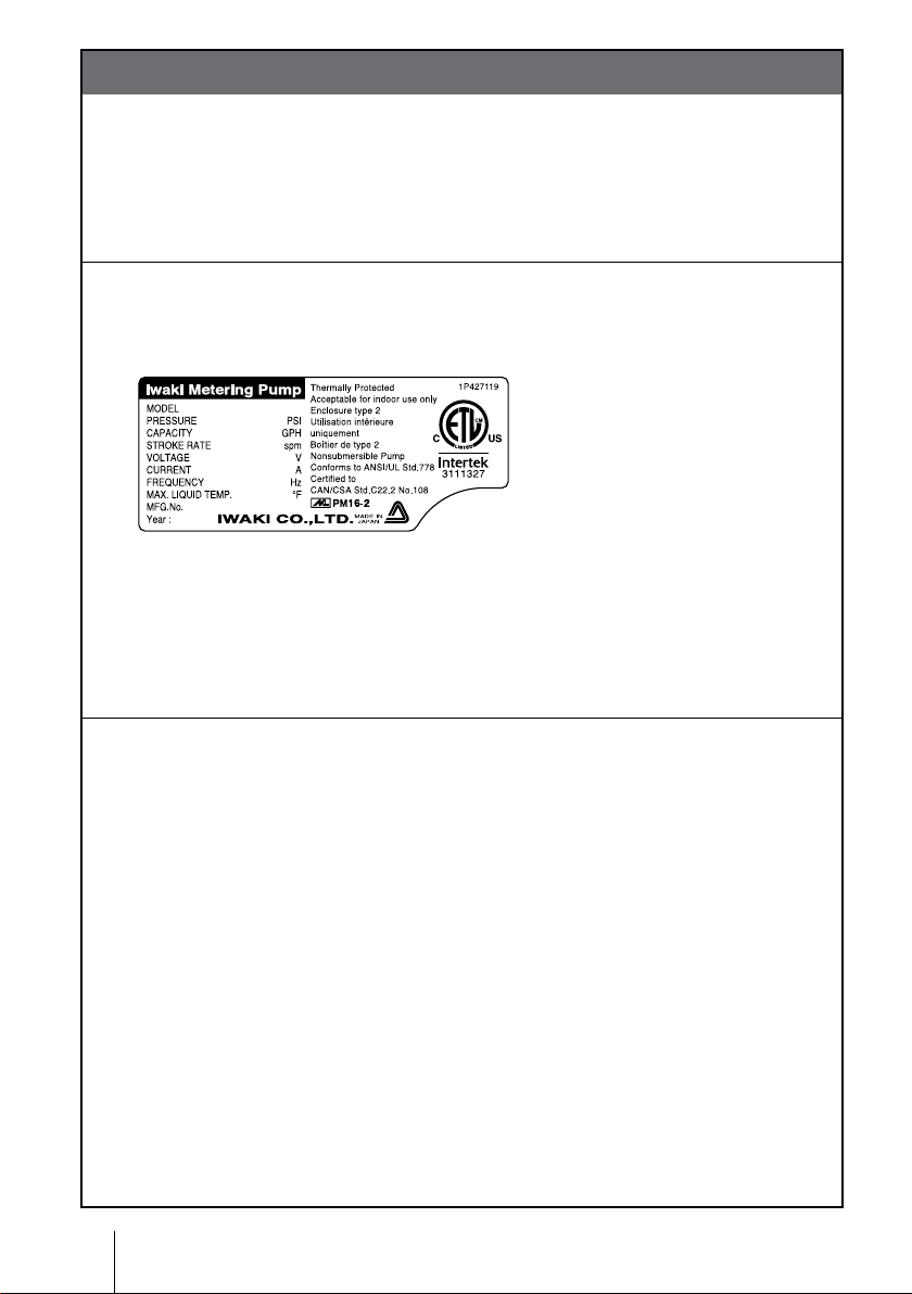
Check the nameplate to see if the information such as model codes, dis-
charge capacity and discharge pressure are as ordered.
b. Check if the delivery is damaged or deformed.
Check for transit damage and loose bolts.
2
Order conrmation
Page 3

Contents
Order conrmation ............................................................................................. 2
Safety instructions ....................................................................... 6
Warning ............................................................................................................. 7
Caution .............................................................................................................. 9
Precautions for use ........................................................................................13
Overview ...................................................................................... 17
Introduction .....................................................................................................17
Pump structure & Operating principle .........................................................17
Features .......................................................................................................18
Operational functions ....................................................................................18
Manual mode ...............................................................................................18
EXT mode ....................................................................................................19
STOP function .............................................................................................19
Part names...................................................................................................... 20
Pump........................................................................................................... 20
Operational panel ........................................................................................21
Basic displays & Pump states ............................................................... 22
Identication codes ....................................................................................... 23
Installation .................................................................................. 24
Pump mounting .............................................................................................. 24
Pipework ......................................................................................................... 25
Tube connection ......................................................................................... 25
Check valve mounting ................................................................................ 27
Wiring .............................................................................................................. 29
Power voltage/Earthing .............................................................................. 29
Signal wire connection.................................................................................31
Input signal ............................................................................................ 32
Contents
3
Page 4

Operation ..................................................................................... 33
Before operation ............................................................................................ 33
Points to be checked .................................................................................. 33
Retightening of pump head xing bolts ...................................................... 33
Use of hexagon wrench instead of a torque wrench ............................. 34
Degassing ................................................................................................... 34
Flow rate adjustment ...................................................................................37
Before a long period of stoppage (one month or more) .............................. 39
Operation programming ............................................................................... 40
Programming ow ....................................................................................... 40
Manual operation .........................................................................................41
EXT operation ............................................................................................. 43
STOP function ............................................................................................ 44
Keypad lock ................................................................................................ 45
Keypad lock activation ........................................................................... 45
Keypad lock release .............................................................................. 45
Maintenance ................................................................................ 46
Troubleshooting ..............................................................................................47
Inspection ....................................................................................................... 48
Daily inspection .......................................................................................... 48
Periodic inspection ..................................................................................... 48
Wear part replacement .................................................................................. 49
Wear part list ............................................................................................... 49
Before replacement .................................................................................... 50
Valve set replacement .................................................................................51
Discharge valve set dismantlement/assembly .......................................51
Suction valve set dismantlement/assembly .......................................... 53
Diaphragm replacement ............................................................................. 54
4
Contents
Page 5

Exploded view ................................................................................................ 57
Pump head & Drive unit .............................................................................. 57
Pump head ................................................................................................. 58
Specications/Outer dimensions ................................................................ 59
Specications ............................................................................................. 59
Pump unit .............................................................................................. 59
Control unit ............................................................................................ 60
Power cable ........................................................................................... 60
Pump colour .......................................................................................... 60
Outer dimensions.........................................................................................61
EJ-B09/-B11/-B16/-B21 VC/VE/VH ........................................................61
EJ-B11/-B16/-B21 TC .............................................................................61
Contents
5
Page 6

Requirement
Safety instructions
Read through this section before use. This section describes
important information for you to prevent personal injury or
property damage.
■ Symbols
In this instruction manual, the degree of risk caused by incorrect use is noted
with the following symbols. Please pay attention to the information associated
with the symbols.
WARNING
CAUTION
Indicates mishandling could lead to a fatal or seri-
ous accident.
Indicates mishandling could lead to personal injury
or property damage.
A symbol accompanies each precaution, suggesting the use of "Caution", "Pro-
hibited actions" or specic "Requirements".
Caution marks Prohibited mark Requirement mark
Caution
Electrical
shock
Prohibited
Do not rework
or alter
Wear
protection
Grounding
Export Restrictions
Technical information contained in this instruction manual might be treated
as controlled technology in your countries, due to agreements in international
regime for export control.
Please be reminded that export license/permission could be required when this
manual is provided, due to export control regulations of your country.
6
Safety instructions
Page 7
WARNING
Turn off power before service
Risk of electrical shock. Be sure to turn off power to stop the pump
and related devices before service is performed.
Couper l’alimentation électrique de la pompe avant intervention
Intervenir sur la pompe sans avoir au préalablement coupé
l’alimentation électrique peut déclencher des décharges électriques. Avant d’entreprendre n’importe quel type d’intervention, veillez à mettre la pompe et tout dispositif connexe hors tension à l’aide
de l’interrupteur prévu à cet effet.
Stop operation
If you notice any abnormal or dangerous conditions, suspend operation immediately and inspect/solve problems.
Electrical
shock
Safety instructions
Arrêter le fonctionnement
Si vous détectez une anomalie ou des signes suspects et inhabituels pendant le fonctionnement, interrompez immédiatement les
opérations et inspectez, résolvez les problèmes.
Do not use the pump in any condition other than its intended purpose
The use of the pump in any conditions other than those clearly
specied may result in failure or injury. Use this product in specied
conditions only.
Se conformer uniquement aux applications prévues
La pompe doit être utilisée conformément à l’usage pour lequel elle
a été prévue et dans le respect de ses caractéristiques techniques.
Toute utilisation non conforme peut entraîner un incident ou endommager le dispositif.
Do not modify the pump
Alterations to the pump carries a high degree of risk. It is not the
manufacturer's responsibility for any failure or injury resulting from
alterations to the pump.
Ne pas modier la pompe
Ne jamais modier une pompe sous peine de causer un incident
grave. Iwaki ne pourra en aucun cas être tenu responsable d’un incident ou de dégâts survenus à la suite d’une modication du dispositif.
Requirement
Prohibited
Do not rework
or alter
WARNING
7
Page 8
Wear protective clothing
Always wear protective clothing such as an eye protection, chemical
resistant gloves, a mask and a face shield during disassembly, assembly or maintenance work. The specic solution will dictate the degree
of protection. Refer to MSDS precautions from the solution supplier.
Porter un équipement de protection
Toujours porter un équipement de protection (lunettes, gants résistants
aux produits chimiques, masque, casque) durant le démontage,
l’assemblage et la maintenance.
Le travail effectué dictera le degré de protection. Référez-vous au
MSDS de la solution proposée par le fournisseur.
Do not damage the power cable
Do not pull, knot, or crush the power cable. Damage to the power
cable could lead to a re or electrical shock if cut or broken.
Ne pas endommager le câble électrique
Ne pas tirer ou faire un nœud avec le câble électrique. Endommager un câble électrique pout provoquer une incendie ou une
décharge électrique.
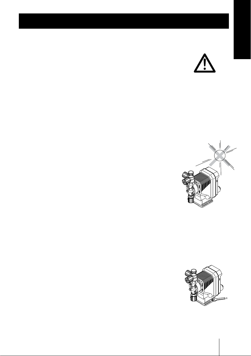
Do not operate the pump in a ammable atmosphere
Do not place explosive or ammable material near the pump.
Wear
protection
Prohibited
Ne pas utiliser la pompe dans une atmosphère explosive
Pour votre sécurité, du matériel dangereux ou inammable ne doit
pas être placé près de la pompe.
Risk of electric shock
This pump is supplied with a grounding conductor and groundingtype attachment plug. To reduce the risk of electric shock, be
certain that it is connected only to a properly grounded, grounding
type receptacle.
Risque de choc électrique
La pompe est fournie avec un conducteur pour mise à la terre et
une prise courant. An de réduire le risque de choc électrique, veillez à ce que la terre soit correctement raccordée.
8
WARNING
Prohibited
Prohibited
Page 9
CAUTION
Qualied personnel only
The pump should be handled or operated by qualied personnel with a
full understanding of the pump. Any person not familiar with the product should not take part in the operation or maintenance of the pump.
Opérateur qualié uniquement
La pompe doit être manipulée ou utilisée par du personnel qualié
connaissant parfaitement la pompe. Tout autre personne étrangère ne
doit pas prendre part à l’utilisation ou à la maintenance de la pompe.
Use specied power only
Do not apply power other than that specied on the nameplate. Otherwise, failure or re may result. Ensure the pump is properly grounded.
Utilisez une tension appropriée uniquement
Ne pas appliquer une autre tension que celle spéciée sur la
plaque signalétique sinon, il peut en résulter une panne ou une incendie. Assurez-vous également de la mise à la terre de la pompe.
Safety instructions
Requirement
Prohibited
Do not run pump dry
Do not run pump dry for more than 30 minutes (even when the
pump runs for degassing). Otherwise, the pump head xing screws
may loosen and liquid may leak. Optimise your system. If the pump
runs dry for a long period (for more than 30 minutes), the pump
head and the valve cases may deform by friction heat and consequently leakage results.
Ne faite pas fonctionner la pompe à sec
Ne faite pas fonctionner la pompe à sec plus de 30 minutes (même
lorsque la pompe fonctionne pour dégazer). Sinon, les visses de
xation de la tête peuvent se dévisser et il peut y avoir une fuite
de liquide. Optimalisez l’installation de façon à ce que la pompe
ne fonctionne pas à sec. Si la pompe fonctionne à sec pour une
longue période (plus de 30 minutes), la tête de la pompe et le guide
de clapets peuvent être déformés par friction causée par la chaleur
et il en résulterait des fuites.
CAUTION
Caution
9
Page 10
Keep electric parts and wiring dry
Risk of re or electric shock. Install the pump where it can be kept dry.
Ne mouillez pas les parties électriques ou les câbles
Risque d’incendie ou de décharge électrique. Installez la pompe
dans un endroit sec.
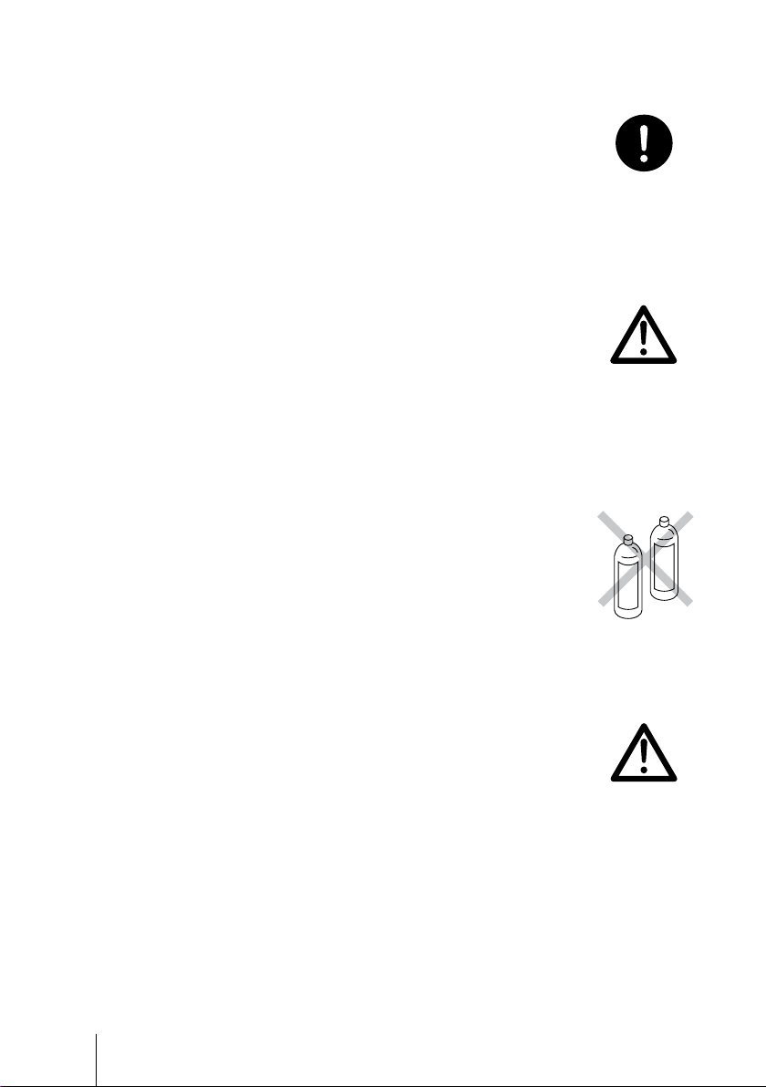
Observe an applicable MSDS
Take account of installation environment. Chemicals should be
controlled in accordance with a MSDS. Do not send potable water
or circulate heated water with this pump.
Prohibited
Observez un « MSDS » applicable
Tenez compte de l’environnement. Les produits chimiques doivent
être surveillés en accord avec un MSDS. Ne pas utilisez cette
pompe avec de l'eau potable ou de l'eau chaude.
Do not install or store the pump:
• In a ammable atmosphere.
• In a dusty/humid environment.
• Where ambient temperature can exceed 0-40ºC.
• In direct sunlight or wind & rain.
N’installez ou ne stockez pas la pompe dans les endroits suivantes:
• Dans une atmosphère inammable
• Dans un endroit poussiéreux ou humide.
• Dans une place où la température n’est pas comprise entre 0 et 40 °C.
• Directement sous le soleil, le vent ou la pluie.
Spill precautions
Ensure protection and containment of solution in the event of
plumbing or pump damage (secondary containment).
Caution
Prohibited
Déversement accidentel
Prenez des mesures protectrices contre tout incident résultant d’un
débit trop important de la pompe ou d’une casse de tuyauterie.
10
CAUTION
Requirement
Page 11
Do not use the pump in a wet location
The pump is not waterproof. Use of the pump in wet or extremely
humid locations could lead to electric shock or short circuit.
N’utilisez pas la pompe sous l’eau
La pompe n’est pas complètement étanche. Utiliser la pompe dans
l’eau ou dans un endroit très humide peut créer une décharge électrique ou un court-circuit.
Grounding
Risk of electrical shock! Always properly ground the pump. Conform to local electric codes.
Mise à la terre
Veillez à ne pas faire fonctionner la pompe sans avoir au préalable
prévu une mise à la terre. Celle-ci permettra d’éviter d’éventuelles
décharges électriques. Vériez que le câble de mise à la terre est
bien branché.
Install a GFCI (earth leakage breaker)
An electrical failure of the pump may adversely affect other devices on the same line. Purchase and install a GFCI (earth leakage
breaker) separately.
Détecteur de fuites à la terre
Un problème électrique peut affecter défavorablement le dispositif.
Achetez et installez un détecteur de fuites à la terre.
Prohibited
Grounding
Electrical
shock
Safety instructions
Preventative maintenance
Follow instructions in this manual for replacement of wear parts. Do
not disassemble the pump beyond the extent of the instructions.
Remplacement des pièces usées
Suivez les instructions de ce manuel pour remplacer les pièces
usées. Ne démontez pas la pompe au-delà des instructions.
Do not use a damaged pump
Use of a damaged pump could lead to an electric shock or death.
N’utilisez pas une pompe endommagée
Utiliser une pompe endommagée peut provoquer une décharge
électrique ou la mort.
CAUTION
Requirement
Prohibited
11
Page 12
Disposal of a used pump
Dispose of any used or damaged pump in accordance with local
rules and regulations. If necessary, consult a licensed industrial
waste disposal company.
Elimination des pompes usées
Elle doit se faire en conformité avec les règles locales en vigueur
(consultez une entreprise certiée et spécialisée).
Check pump head bolts
Liquid may leak if any of the pump head bolts become loose.
Tighten the bolts evenly to the following torque in diagonal order
before initial operation and at regular intervals.
Tightening torque
19 lb-in
Serrez la tête de pompe
La pompe peut fuiter si les boulons sont desserrés. Resserrez les
boulons diagonalement et uniformément avant la première utilisation Resserrez les boulons régulièrement pour éviter tout fuite.
Couple de serrage
19 lb-in
Solution compatibility
This pump has been evaluated for use with water only. The suitability of this pump for use with liquids other than water, such as acid
and alkaline, is the responsibility of the user. For liquids other than
water, select the best-suited liquid end material combination using a
chemical compatibility chart.
Requirement
Caution
Compatibilité avec la solution
Cette pompe a été évaluée pour l’utilisation avec l’eau uniquement.
L’aptitude de cette pompe à être utilisée avec d’autres produits, tels
que les acides et les alcalins, est de la responsabilité de l’utilisateur.
Pour des liquides autres que l’eau, choisissez le matériel le plus
compatible selon la résistance chimique.
12
CAUTION
Caution
Page 13
Precautions for use
• Electrical work should be performed by a qualied electri-
cian. Otherwise, personal injury or property damage could
result.
Safety instructions
Le raccordement électrique de la pompe doit être effectué
par du personnel qualié sinon, il pourrait y avoir un dom-
mage corporel ou incorporel.
• Do not install the pump:
–In a ammable atmosphere.
–In a dusty/humid place.
–In direct sunlight or wind & rain.
– Where ambient temperature can exceed 0-40ºC.
Protect the pump with a cover when installing it out of
doors.
Ne pas installer la pompe dans les endroits suivants:
–Dans une atmosphère inammable
–Dans une atmosphère poussiéreuse ou humide.
– Sous les rayonnements du soleil, dans le vent ou sous la pluie.
– La température ambiante doit être comprise entre 0 et 40°C.
Protégez la pompe par un capot si vous l’installez dehors.
Caution
• Select a level location, free from vibration, that won't hold
liquid. Anchor the pump with four M5 bolts so it doesn't
vibrate. If the pump is not installed level, output may be
affected.
Choisissez un endroit où il n’y a pas de vibrations et où le
liquide peut s’évacuer. Fixez la pompe à l’aide de visses
M5 de façon à ne pas avoir de vibrations. Si la pompe est
inclinée, le débit peut être réduit.
Precautions for use
13
Page 14
• When two or more pumps are installed together, vibration
may be signicant, resulting in poor performance or failure.
Select a solid foundation (concrete) and fasten anchor bolts
securely to prevent vibration during operation.
Si plusieurs pompes sont installées ensemble, elles intera-
gissent et les vibrations peuvent devenir importantes, ce
qui engendre des performances médiocres ou des ratures.
Choisissez un endroit solide et xez les boulons correcte-
ment pour évitez les vibrations pendant le fonctionnement.
• Allow sufficient space around the pump for easy access
and maintenance.
Prévoyez de l’espace autour de la pompe pour faciliter
l'accès et la maintenance.
• Install the pump as close to the supply tank as possible.
Installez la pompe le plus près possible du tank de produit.
• When handling liquids that generate gas bubbles (sodium
hypochlorite or hydrazine solution), install the pump in a
cool and dark place. Flooded suction installation is strongly
recommended.
Caution
Caution
Caution
Installez la pompe dans une place froide à l’abri du soleil
lorsqu’il s’agit du dosage de produits dégazant tels que
l’hypochlorite de sodium ou l’hydrazine. Mettre la pompe en
charge est vivement recommandé.
14
Precautions for use
Caution
Page 15

• Use care handling the pump. Do not drop. An impact may
affect pump performance. Do not use a pump that has
been damaged to avoid the risk of electrical damage or
shock.
Veillez à ne pas laisser tomber la pompe sur le sol. Un
impact important pourrait réduire les performances de la
pompe. Ne pas utiliser une pompe endommagée sinon il
pourrait y avoir un courant de fuite ou une décharge élect-
rique.
• The pump has a rating of IP65 equivalent, but is not water-
proof. Do not operate the pump while wet with solution or
water. Failure or injury may result. Immediately dry off the
pump if it gets wet.
Safety instructions
Le pompe est IP65 équivalent mais n’est pas complète-
ment étanche. Ne pas laisser la pompe couverte de liquide
pompé ou sous la pluie. Il pourrait y avoir des ratés ou
préjudices. Si la pompe a été mouillée, sechez-la directe-
ment.
• Do not close discharge line during operation. Solution may
leak or piping may break. Install a relief valve to ensure
safety and prevent damaged plumbing.
Ne fermez pas la ligne de refoulement lorsque la pompe est
en fonctionnement sinon il pourrait y avoir des fuites de liq-
uide ou la tuyauterie pourrait céder. Installez une soupape
de sécurité pour des raisons de sécurité et pour éviter tout
dommage de la tuyauterie.
Caution
Caution
Precautions for use
15
Page 16
• Solution in the discharge line may be under pressure.
Release the pressure from the discharge line before dis-
connecting plumbing or disassembly of the pump to avoid
solution spray.
Le liquide au refoulement peut être sous pression.
Relâchez la pression du refoulement avant de démonter la
pompe ou d’enlevez le tubage pour éviter tout jet de liquide.
• Wear protective clothing when handling or working with
pumps. Consult solution MSDS for appropriate precautions.
Do not come into contact with residual solution.
Portez un équipement de sécurité lorsque vous manipulez
la pompe. Consultez le MSDS pour utilisez les précautions
appropriées .Evitez tout contact avec le liquide chimique.
• Do not clean the pump or nameplate with a solvent such
as benzine or thinner. This may discolour the pump or
erase printing. Use a dry or damp cloth or a neutral
detergent.
Ne nettoyez pas la pompe ou la plaque signalétique à
l’aide d’un solvant comme le benzène ou le white spirit.
Cela pourrait décolorer la pompe ou effacer l’impression.
Utilisez un tissu sec ou mouillé avec de l’eau ou un déter-
gent neutre.
Requirement
Caution
Thinner
Benzine
• This pump has been evaluated for use with water only.
Cette pompe a été testée uniquement avec de l'eau.
16
Precautions for use
Caution
Page 17
Overview
Pump characteristics, features and part names are described
in this section.
Introduction
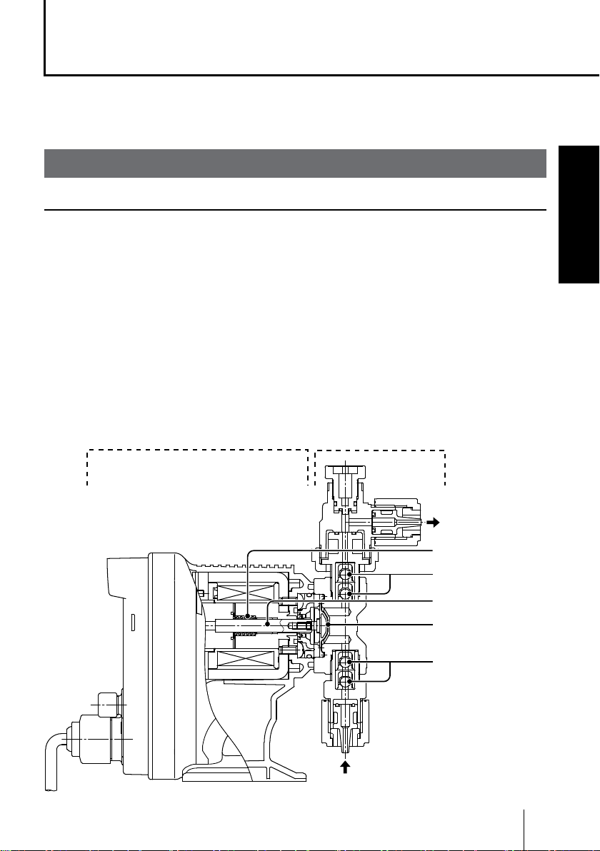
Pump structure & Operating principle
The EJ series is a diaphragm metering pump which consists of a pump head
and a drive unit with a built-in controller. A diaphragm is directly driven by elec-
tromagnetic force.
Principle of operation
The pulse signal via the PCB generates the electromagnetic force to make
reciprocating motion with the assistance of the spring force. The reciprocating
motion is transferred to a diaphragm through a plunger and then volumetric
change occurs in the pump head. This action transfers liquid along with pump
head valve action.
Control unit Pump head
OUT
Spring
Pump head valve
Overview
IN
Plunger
Diaphragm
Pump head valve
Introduction
17
Page 18
Features
● Multivoltage operation
The EJ series is a multivoltage type (U:100-120VAC, U2:100-240VAC) and
can be selected without local power limitations.
● High turndown ratio
Digitally-controlled spm range is 1-360spm.
● IP rating of 65 equivalent
This pump is not waterproof. Protect the pump with a cover when installing it
out of doors.
Operational functions
Manual mode
Run/stop the pump by the start/stop key. A stroke rate (MAN speed) can be
changed in the range of 1-360spm by the up key at any time during operation
or stop. See page 41 for detail.
*The pump can also be turned ON/OFF by switching the main power.
Key operation
(Start/Stop key)
Pump operation
18
Operational functions
Run Run
Stop
Stop
Page 19
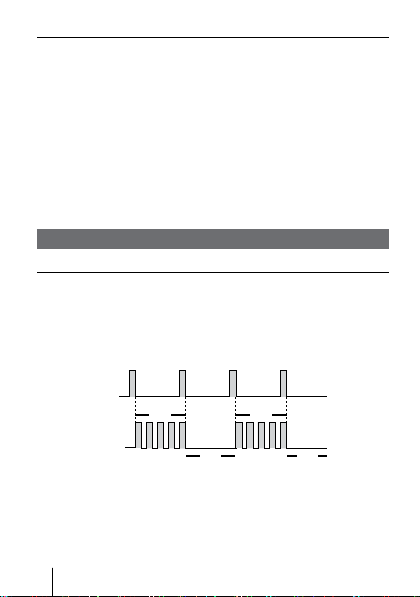
EXT mode
The pump operation by the external signal. In this mode, the multiplier is xed
to 1 and the pump makes one shot at every input of the signal. See page 43 for
detail.
Example) The pump makes one shot per signal.
Pulse signal input
Pump operation
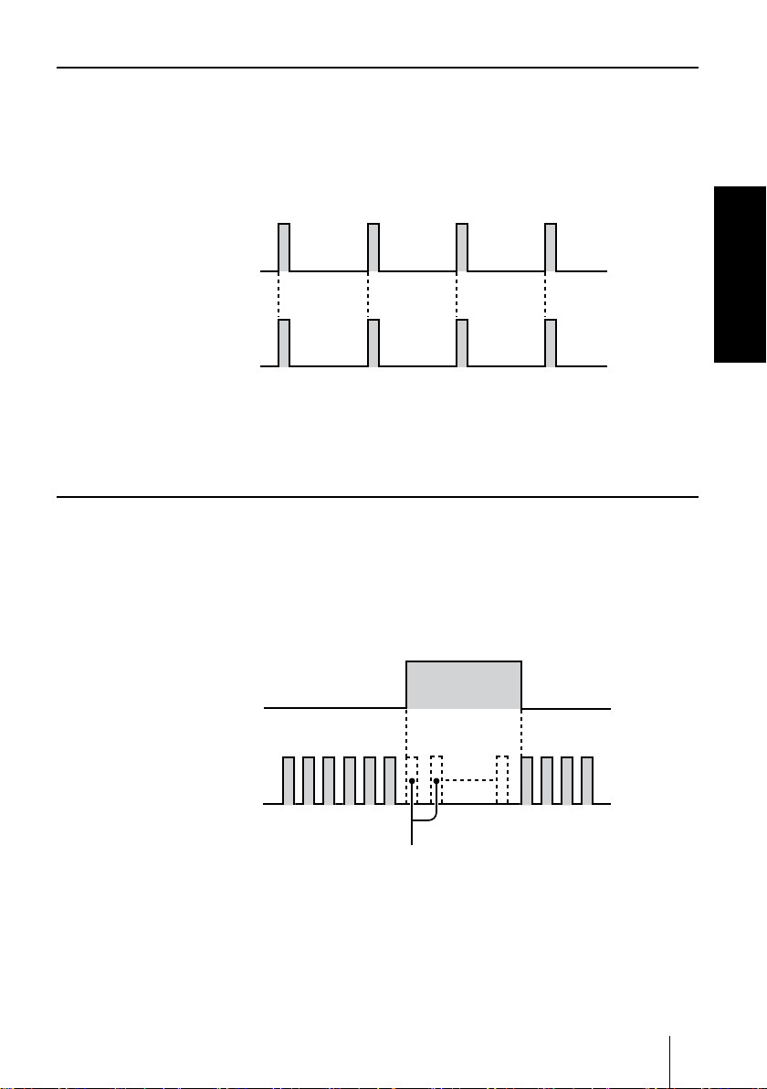
STOP function
The start/stop of the pump can be controlled by the external STOP signal. See
page 44 for detail.
*The pump resumes operation when the STOP signal is released.
Overview
STOP signal input
Pump operation
Run Run
Stop
The pump stops running while
the STOP signal is inputted.
Operational functions
19
Page 20

Part names
Pump
Air vent por t
Always connect a tube. Be sure
to return the tube end to a supply
tank or a container.
A circumferential direction of the
port can be changed up to 90
degrees counterclockwise from
the original position.
Outlet
Air vent body
Inlet
Adjusting screw
Used for opening the air vent port.
20
Part names
Power cable
Pump head
Base
Always fix with bolts.
Control unit
Used for the start/stop of
the pump and stroke rate
adjustment/programming.
Nameplate
Describes the pump
specifications.
EXT terminal
(5-pin DIN connector)
Remove the protective
cap before use.
Page 21

Operational panel
ON LED
Lights as turning on power
and flashes at each stroke.
Display
Stroke rate and operational
status are shown here.
ON
START
STOP
UP key
Used for increasing numeric values. If this key is kept pressed, the
value rises faster. The EJ doesn't
have the DOWN key, so if you
want a lower spm, first get to the
max 360 spm and then push this
key once. The spm will return to 1.
Overview
START/STOP key
Used for starting/stopping the pump. If
pushed while the UP key is depressed,
the pump enters EXT mode.
Part names
21
Page 22

■ Basic displays & Pump states
Shows a pump speed in spm. The spm
flashes during operation in MAN and EXT
modes. The indication changes to "- - -"
when the pump enters maintenance mode.
Display info ON LED lights
A wait state in MAN mode:
The display shows the MAN
speed in spm.
―
STOP signal is entered in MAN
mode. If the spm ashes, it
means the pump is just suspended and will restart as the signal is
turned OFF.
STOP signal is entered in EXT
mode. If the spm ashes, it
means the pump is just suspended and will restart as the signal is
turned OFF.
Represents the pump
is in EXT mode.
Represents the pump
is receiving the STOP
signal.
Represents keypads are locked.
ON LED ushes
(in sync with each shot)
Operation in MAN mode:
A current spm ashes (not in
sync with a pump shot).
Operation in EXT mode:
A current spm ashes (not in
sync with a pump shot).
―
―
22
Part names
―
Keypads are locked in a suspended MAN/EXT mode with the
STOP signal.
The pump is in maintenance
mode. When extending the diaphragm, the display ashes.
Keypads are locked and any key
operation is cancelled.
―
―
Page 23

Identication codes
The model codes of the pump/drive units represent the following information.
EJ - B 11 VC U R -
a b c d e f g h i
a. Series name
EJ: Multivoltage electromagnetic metering pump
b. Drive unit (Average power consumption)
B: 15W
c. Diaphragm effective diameter
09: 8mm 11: 10mm 16: 15mm 21: 20mm
d. Wet end materials
Code Pump head Valve O ring Valve seat Gasket Diaphragm
VC
VH HC276
VE
TC PVDF FKM FKM
Material code
PVC : Transparent polyvinyl chloride PVDF : Polyvinylidene diuoride
HC276 : HASTELLOY C276 FKM : Fluorine-contained rubber
EPDM : Ethylene-propylene rubber PTFE : Polytetrauoroethylene
PVC
Alumina ceramic FKM FKM
EPDM EPDM
Alumina ceramic
PTFE
(EPDM is not a
wet end.)
e. Tube I.D.
Material VC VH VE TC
No code ø1/4"×ø3/8" ø1/4"×ø3/8" ø1/4"×ø3/8" ø1/4"×ø3/8"
1 ø4×ø9 ø4×ø9 ø4×ø9 ―
2 ø4×ø6 ø4×ø6 ø4×ø6 ø4×ø6
3 ø6×ø8 ø6×ø8 ø6×ø8 ø6×ø8
7 ø1/4"×ø3/8" ø1/4"×ø3/8" ø1/4"×ø3/8 " ø1/4"×ø3/8"
23 ø6×ø12 ― ― ―
24 ø5×ø8 ― ― ø5×ø8
Overview
PTFE
+ EPDM
f. Power cable
U: American 115VAC type (rated voltage 100-120VAC, with 5-15 plug)
U2: American 230VAC type (rated voltage 100-240VAC, with 6-15 plug)
g. Control unit function
R: With external control
h. Special version
i. Special conguration
Identication codes
23
Page 24

Installation
This section describes the installation of the pump, tubing and
wiring. Read through this section before work.
Observe the following points when installing the pump.
• Risk of electrical shock. Be sure to turn off power to stop the pump and
related devices before service is performed.
• If you notice any abnormal or dangerous conditions, suspend operation
immediately and inspect/solve problems.
• Do not place explosive or ammable material near the pump.
• Do not use a damaged pump. Use of a damaged pump could lead to an
electric shock or death.
Pump mounting
Select an installation location and mount the pump.
Necessary tools
• Four M5 bolts (pump mounting)
• Adjustable wrench or spanner
Select a suitable place.
1
Select a level location, free from vibration, that won't hold liquid. See
page 13 for detail. Flooded suction is recommended when handling a
gaseous liquid such as sodium hypochlorite.
Anchor the pump with the M5 bolts.
2
Be sure to x the pump at four points.
NOTE
Select a level location. If the pump is not installed level,
output may be affected.
24
Pump mounting
Page 25

Pipework
Connect tubes to the pump and install a check valve.
Before operation
• Cut the tube ends at.
Necessary tools
• Adjustable wrench or spanner
Tube connection
a. Pass a tube into the tting nut and
hoes stopper and then slide it down to
the hose adapter as far as it will go.
b. Fit the tube end (hose adapter) to the
tting. Then hand tighten the tting nut.
c. Retighten the tting nut by turning it
180 degrees with an adjustable wrench
or spanner.
* The plastic tting nut may be broken if it is
tightened too much.
Tube end (Side view)
Installation
Tube
Fitting nut
Hose stopper
a
b
Hose adapter
O ring
Fitting
Pipework
25
Page 26

Connect tubes into the inlet and
1
outlet.
Connect an air bleed tube into the
2
air vent port.
Route back the other tube end to a
supply tank or a container.
Outlet
Tube
Inlet
Tube
Air vent port
Air bleed tube
Determine an air vent port direction.
3
The air vent port can rotate 90 de-
grees.
a. Turn the lock nut anticlockwise.
b. Adjust the direction of the air vent
port.
c. Hand-tighten the lock nut, holding
the air vent body A.
d. Turn the lock nut 90 degrees
clockwise further with an adjustable
wrench or spanner.
26
Pipework
Air vent port
Air vent body A
Lock nut
Page 27

Check valve mounting
Install an optional check valve to the EJ for the prevention of a back ow, si-
phon and overfeeding. In the following cases be sure to install the check valve.
• A suction side liquid level is higher than a discharge side or an injection point
at atmospheric pressure.
Suction side
Discharge side
• A discharge side liquid level is higher than a suction side but the distance is
5m or below.
5m or below
Discharge side
Suction side
• A suction line pressure is higher than a discharge line pressure.
Installation
• A discharge pressure (including pipe resistance and discharge head) is below
0.13MPa .
Pipework
27
Page 28

Mount a check valve at the discharge tube end.
1
* The CAN check valve has R1/2 and R3/8 thread connections as well as a ø9
tube connection. Cut off unnecessary sections before use.
CAN check valve
Outer dia ø9R1/2
R3/8
* The CBN check valve of which the both ends are tube connections is also
available. Contact us or your nearest distributor.
CBN check valve
NOTE
Periodically clean or replace a check valve with new one for the prevention of crystal
clogging, especially when using sodium hypochlorite.
Tubing layout
Flooded suction application Suction lift application
Air vent line
Relief valve
Check valve
Accumulator/Chamber
Pump
Relief valve
Check valve
Accumulator/Chamber
Pump
Air vent line
NOTE
Flooded suction is recommended when handling a gaseous liquid such as sodium
hypochlorite.
28
Pipework
Page 29

Wiring
Wiring for a power voltage, earthing and an external signal.
Observe the following points during wiring work.
• Electrical work should be performed by a qualied electrician. Always
observe local electric codes.
• Observe the rated voltage range, or the electrical circuit in the control
unit may fail.
• Do not perform wiring work while electric power is ON. Otherwise, an
electrical shock or a short circuit may result. Be sure to turn off the power
before wiring work.
• Be careful for the power not to be turned on during work.
• The power cable is not replaceable.
• The DIN 5-pin male-connector is protected with a protective cap. Do not
remove the cap unless the connector is used, or failure may result.
• This pump is supplied with a grounding conductor and ground-
ing-type attachment plug. To reduce the risk of electric shock,
be certain that it is connected only to a properly grounded,
grounding type receptacle.
Installation
Necessary tools
• Adjustable wrench or spanner • Phillips screw driver
Power voltage/Earthing
Check that the main power is turned off.
Plug the pump into the outlet.
1
*Make sure the pump is earthed properly.
Wiring
29
Page 30

NOTE
TIME
• Do not share a power source with a high power device which may generate surge
voltage. Otherwise an electronic circuit may fail. The noise caused by an inverter also
affects the circuit.
• Energize the pump with a power voltage via a mechanical relay or switch. Do not
uctuate the voltage, or CPU may malfunction. See page 31 for the precautions for
ON-OFF control by a mechanical relay.
Apply power sharply Do not apply gradually
POWER
ON
OFF
POWER
TIME
ON
OFF
Surge voltage
The electronic circuit in this pump may fail due to surge voltage. Do not
place the pump close to a high power device of 200V or more which may
generate large surge voltage. Otherwise, take any of the following meas-
ures.
• Install a surge absorption element (ex. a varister with capacity of 2000A
or more) via power cable.
Surge absorption element
Recommended varisters
SUNTAN TSV14D511K
Panasonic ERZV14D511
See manufacturer's catalogues for detail.
• Install a noise cut transformer via power cable.
Noise cut transformer
30
Wiring
Page 31

Precautions for ON-OFF control by a mechanical relay
This pump is equipped with CPU. Always start/stop the pump by the STOP
signal for ON-OFF control. Try not to turn on and off the main power. Oth-
erwise, observe the following points.
• Do not turn ON/OFF power voltage more than six times per hour.
• When using a mechanical relay for ON-OFF operation, its contact capac-
ity should be 5A or more. Contact point may fail if it is less than 5A.
• If a mechanical relay with the contact capacity of 5A is used, the maxi-
mum allowable ON/OFF operation is about 150,000 times. The contact
capacity should be 10A or more when making ON-OFF operation over
150,000 times or sharing a power source with a large capacity equip-
ment. Otherwise a contact point may fail by surge voltage.
• Use a solid state relay (SSR) as necessary (such as the OMRON G3F).
See manufacturer's catalogues for detail.
Signal wire connection
Points to be checked
• Check that the main power is turned off.
The pump is still charged right after turning off power. Wait for one min-
ute before wiring.
Installation
Applicable cables
Use our optional connector cables below or purchase DIN 5-pin female
connector cables when using signal input.
Binder connector cables
5-pin : 713 series 99-0436-10-05 Input signal.
Wiring
31
Page 32

■ Input signal
To run the pump in EXT mode or to use STOP function, connect signal wires to
the EXT terminal via a DIN 5-pin connector.
• When using an open collector:
Pay attention to polarity. PIN 1 and 2 are plus (+), and PIN 3 and 4 are minus (-).
• When using a contact:
Use a mechanical relay designed for an electronic circuit. Its minimum application
load should be 3mA or less.
2
3
1
5
4
2
3
1
5
4
PIN 1 : Pulse (brown)
PIN 2 : STOP (white)
PIN 3 : COM (blue)
PIN 4 : COM (black)
PIN 5 : N.C. (green)
* Each terminal is coloured as
above for our optional cable.
Wiring for
Pulse signal
Wiring for
STOP signal
The PIN 5 is not used.
NOTE
• Do not lay on these signal cables in parallel with a power cable or combine them in a
concentric cable (ex. 5 wires cable). Otherwise noise is generated through the cables
due to induction effect and it results in malfunction or failure.
• The following products are the recommended SSRs (Solid State Relays) for signal
input. Any other SSRs may cause malfunction. See manufacturer's information for
details on these SSRs.
–OMRON G3FD-102S or G3FD-102SN
–OMRON G3TA-IDZR02S or G3TA-IDZR02SM
• When using a mechanical relay for signal input, its minimum application load should
be 3mA or below.
• Insert the DIN connector as far as it will go and then rotate the outer ring to x it.
• Our optional cable has 5 wires. Cut off a green wire that is not used.
• PIN 5 is not used. Do not short-circuit it to COM 3 or 4.
*Use either a no-voltage contact or an open collector.
* Set pulse duration in 10-100ms and the number of pulses at or below 360 pulses per
minute.
32
Wiring
Page 33

Operation
This section describes pump operation and programming.
Run the pump after pipework and wiring is completed.
Before operation
Check a ow rate, tubing and wiring. And then perform degassing and ow rate
adjustment before starting operation.
Points to be checked
Before operation, check if...
• Liquid level in a supply tank is enough.
• Tubing is securely connected and is free from leakage and clogging.
• Discharge/suction valves are opened.
• A power voltage is in the allowable range.
• Electrical wiring is correct and is free from the risk of short circuit and electri-
cal leakage.
Retightening of pump head xing bolts
Important
The pump head xing bolts may loosen when plastic parts creep due to tem-
perature change in storage or in transit, and this can lead to leakage. Be sure
to retighten the bolts evenly to 19 lb-in in diagonal order before starting opera-
tion.
*Tighten xing bolts once every three months.
Before operation
Operation
33
Page 34

■ Use of hexagon wrench instead of a torque wrench
Fasten the xing bolts as tight as can be by the hand with the straight long part
of a hexagon wrench (a) and further turn the bolts clockwise 90 degrees with
the short part (b).
a b
Straight long
part
Short part
90°
Degassing
The gas needs to be expelled from the pump and tubing by degassing. Normal
performance can not be obtained with gas in the pump. Conduct degassing in
the following cases.
• When the pump starts to run for the rst time
• When a ow rate is too low
• After liquid is replaced in a supply tank
• After a long period of stoppage
• After maintenance and inspection
NOTE
• Both gas and chemical come out together through an air bleed tube. Place the end of
the tube in a supply tank or a container.
• Some chemicals may cause skin trouble or damage component parts. When your
hand or component parts get wet with chemical liquid, wipe off immediately.
34
Before operation
Page 35

Points to be checked
• An air bleed tube is connected to the pump.
Turn on power.
1
The LED lights and a display related to the
current mode appears on the screen.
* The pump waits in the MAN mode when the
power is turned ON with a default setting or calls
up the last selected mode with other settings.
Air bleed tube
ON
START
STOP
LED
Use the UP key to set a stroke rate to 360spm.
2
• This programming is not necessary when the display already shows
360. Move to the next step.
• If the key is pressed and held, the spm will quickly increases to the
max rate.
Rotate the adjusting screw two revolutions
3
anticlockwise to open the air vent port.
* Do not rotate it three revolutions. Otherwise,
liquid may come out from the adjusting screw.
Adjusting screw
Before operation
Operation
35
Page 36

Push the start/stop key and run the pump for more than ten minutes.
4
ON
START
STOP
Push the start/stop key and stop the pump.
5
Rotate the adjusting screw clockwise to close the air vent port.
6
Check liquid is discharged.
7
*Degassing is required again if the pump does not discharge liquid.
Check connections for leakage.
8
Degassing has now been completed.
ON
START
STOP
36
Before operation
Page 37

Flow rate adjustment
A ow rate can be adjusted only by changing a stroke rate (stroke length
adjustment is not available). A stroke rate can be set by keypad operation from
1 to 360spm. The relation between a ow rate* and a stroke rate is shown as
below.
100
%
Flow rate
75
50
25
* The discharge capacity described on
the nameplate is the value at 100%.
0
Turn on power and call up manual
1
180 3 60 spm
Stroke rate
mode.
Enter manual mode to indicate a
stroke rate on the screen.
• Push the start/stop key when the
pump is in the EXT mode.
• When "STOP" appears on the
screen, suspend the STOP signal.
Determine a stroke rate that will meet a required ow.
2
See the above table.
ON
START
STOP
Operation
Before operation
37
Page 38

Use the UP key to adjust a stroke rate.
3
• spm increases as pushing the UP keys.
• Press and hold the key for three seconds for quick increment. Quick
increment stops at 360spm. 360spm skips to 1spm when the key is
released and pushed once.
ON
START
STOP
Measure a ow rate.
4
If a ow rate is lower than a specied level, increase a stroke rate.
5
Measure the ow again to see the specied level is obtained.
6
ON
START
STOP
38
Before operation
Page 39

Before a long period of stoppage (one month or more)
Clean wet ends and the inside of tubing.
• Run the pump with clean water for about 30 minutes to rinse chemicals off
from the pump head and piping.
Before unplugging the pump
• Always stop the pump by key operation and wait for three seconds before
unplugging the pump. Otherwise, the last key operation may not be put in
memory. In this case the pump unintentionally starts to run as powered on,
discharging liquid.
When the pump does not transfer liquid at resuming operation.
• Clean the valve sets and remove foreign matters.
• If gas is in the pump head, expel gas and readjust a ow rate. See "Degas-
sing" on page 34 and "Flow rate adjustment" on page 37 for detail.
Operation
Before operation
39
Page 40

Operation programming
Operation at each mode is individually set and controlled by keypad operation.
Select a proper mode to make optimal operation.
Programming ow
Maintenance mode
3 sec.
Power ON
WAIT mode
Power ON while the UP key is pressed.
The maintenance mode will come up
after 3 seconds.
Display flashes and diaphragm
is extended to the full.
spm setting
and
MAN mode
EXT mode
Keypad lock (Ex.)
MAN mode operation
3 sec
3 sec
* The maintenance mode is used for the replacement of a diaphragm.
40
Operation programming
Keypads are locked.
Page 41

Manual operation
Turn on power.
1
The LED lights and a display related to
the current mode appears on the screen.
* The pump waits in the manual mode when
the power is turned ON with a default setting or calls up the last selected mode when
powered on with other settings.
Enter WAIT mode.
2
Move to the next step when spm (1-360) is shown on the screen.
When "EXT" is shown on the screen:
Push the start/stop key once to return to the WAIT mode.
ON
START
STOP
ON
START
STOP
When "STOP" is shown on the screen:
Release the STOP signal.
ON
START
STOP
Operation programming
Operation
41
Page 42

Use the UP key to set a stroke rate.
3
• spm increases as pushing the UP key.
• Press and hold the key for three seconds for quick increment. Quick
increment stops at 360spm. 360spm skips to 1spm when the key is
released and pushed once.
ON
START
STOP
Push the start/stop key.
4
The LED and spm indication blink as the pump starts to run.
*Only the LED blinks in sync with the pump operation.
ON
START
STOP
ON
START
STOP
ON
START
STOP
42
Operation programming
Page 43

EXT operation
The pump operation is controlled by the external (pulse) signal. In this mode,
the pump runs in sync with each external signal.
NOTE
The maximum stroke rate is 360spm in the EXT mode.
Enter WAIT mode.
1
When "EXT" is shown on the screen:
The pump is already in the EXT mode and
waiting for the input of the external signal.
ON
When "STOP" is shown on the screen:
Release the STOP signal.
Push the UP key while pressing the start/stop key.
2
START
STOP
The mode changes to the EXT mode and starts running as receiving the
external signal.
* The displayed spm shows an actual pump speed in the EXT mode.
ON
START
STOP
ON
START
STOP
Operation
Operation programming
43
Page 44

STOP function
The start/stop of the pump operation can be controlled by the external stop
signal. The display changes as below when the STOP signal is inputted.
MAN mode
ON
EXT mode
ON
START
STOP
START
STOP
STOP signal
STOP signal
ON
START
STOP
ON
START
STOP
44
Operation programming
Page 45

Keypad lock
Keypad lock can be active in the MAN or EXT mode for the prevention of erro-
neous key operation. The "LOCK" indication appears while keypads are locked.
NOTE
Any key operation is not acceptable when the keypads are locked. In an emergency,
unplug the pump to stop operation. Plugging in the pump, keypads are locked again.
■ Keypad lock activation
Press and hold the start/stop key for three seconds.
1
ON
START
STOP
ON
START
STOP
3 sec
■ Keypad lock release
Press and hold the start/stop key for three seconds.
1
Keypad lock is released and key operation becomes acceptable.
ON
START
STOP
ON
START
STOP
3 sec
Operation
Operation programming
45
Page 46

Maintenance
This section describes troubleshooting, inspection, wear part
replacement, exploded views and specications.
Important
• Follow instructions in this manual for replacement of wear parts. Do not
disassemble the pump beyond the extent of the instructions.
• Always wear protective clothing such as an eye protection, chemical re-
sistant gloves, a mask and a face shield during disassembly, assembly or
maintenance work. The specic solution will dictate the degree of protec-
tion. Refer to MSDS precautions from the solution supplier.
• Risk of electrical shock. Be sure to turn off power to stop the pump and
related devices before service is performed.
Before unplugging the pump
Always stop the pump by key operation. And wait for three seconds before
unplugging the pump. Otherwise, the last key operation to stop the pump
may not be put in memory. In this case the pump unintentionally starts to
run as powered on, discharging liquid.
46
Maintenance
Page 47

Troubleshooting
First check the following points. If the following measures do not help removing
problems, contact us or your nearest distributor.
States Possible causes Solutions
The pump
does not run
( blank LED
or screen).
Liquid can
not be
pumped up.
A ow rate
uctuates.
Liquid leaks. The tting or the air vent body is
Power voltage is too low. • Observe the allowable voltage
range of 90-264VAC
The pump is not powered. • Check the switch if it is installed.
• Correct wiring.
• Replace a breaking wire to new
one.
A PCB has failed. • Replace the pump.
Air lock in the pump • Expel air. See page 34.
Air ingress through a suction line. • C o r r e c t tubing.
A valve set is installed upside
down.
Valve gaskets are not installed. • Install valve gaskets.
Foreign matters are stuck in the
pump head valves.
A ball valve is stuck on a valve
seat.
Air stays in the pump head. • Expel air. See page 34.
Overfeeding occurs. • Mount a check valve. See page
Foreign matters are stuck in the
pump head valves.
Diaphragm is broken. • Replace diaphragm.
Pressure uctuates at an injection
point.
mounted loose.
The pump head is mounted loose. • Retighten as necessary. See page
O rings or valve gaskets are not
installed.
Diaphragm is broken. • Replace the diaphragm.
Excessive discharge pressure. • Check that a discharge line is not
• Reinstall the valve set.
• Dismantle, inspect and clean the
valves. Replace as necessary.
• Dismantle, inspect and clean the
valve. Replace as necessary.
27.
• Dismantle, inspect and clean the
valves. Replace as necessary.
• Maintain a pressure constant at
an injection point by optimizing
tubing or by relocating the point.
• Retighten as necessary.
33.
• Install O rings and valve gaskets.
closed.
• Check if tubing is not clogged.
Maintenance
Troubleshooting
47
Page 48

Inspection
Perform daily and periodic inspection to keep pump performance and safety.
Daily inspection
Check the following points. Upon sensing abnormality, stop operation immedi-
ately and remove problems according to "Troubleshooting".
When wear parts come to the life limit, replace them with new ones. Contact us
or your nearest distributor for detail.
No. States Points to be checked How to check
1 Pumping • If liquid is pumped. Flow meter or visual
inspection
• If the suction and discharge pressure
are normal.
• If liquid has deteriorated, crystallized
or precipitated.
2 Noise and vibration • If abnormal noise or vibration occurs.
They are signs of abnormal operation.
3 Air ingress from
pump head joints
and a suction line
• If leakage occurs.
• If pumped liquid includes air bubbles,
check lines for leakage and retighten
as necessary.
Check specications.
Visual or audio
inspection
Visual or audio
inspection
Visual or audio
inspection
Periodic inspection
Retighten the pump head mounting bolts evenly to the 19 lb-in in diagonal
order (once three months).
* Mounting bolts may loosen in operation. How fast the bolts start to loosen is depend-
ing on operating conditions.
*A hexagon wrench can be used for a torque wrench. See page 34.
48
Inspection
Page 49

Wear part replacement
13
To run the pump for a long period, wear parts need to be replaced periodically.
It is recommended that the following parts are always stocked for immediate
replacement. Contact us or your nearest distributor for detail.
Precautions
• Solution in the discharge line may be under pressure. Release the pres-
sure from the discharge line before disconnecting plumbing or disassem-
bly of the pump to avoid solution spray.
• Rinse wet ends thoroughly with tap water.
• Each time the pump head is dismantled, replace the diaphragm, O rings,
and valve sets with new ones.
Wear part list
Parts # of parts Estimated life
12
9
11
Valve set 2 sets
Pump
10
9
11
10
8000 hours
19
20
6
18
26
Wear part replacement
Diaphragm 1
O ring See page 57.
* Wear part duration varies with the pressure, temperature and characteristics of liquid.
* The estimated life is calculated based on the continuous operation with clean water at
ambient temperature.
Maintenance
49
Page 50

Before replacement
First release pressure from the pump head.
Stop the pump operation.
1
Rotate the adjusting screw two revolutions anticlockwise to open
2
the air vent port.
NOTE
Do not rotate it three revolutions or more. Otherwise, the adjusting screw may
come off with solution spray.
Check the discharge line and the pump head are depressurized.
3
Liquid pressure is released from the air vent port in the form of solution
spray.
NOTE
If pressurized liquid is not expelled, run the pump with an opened air vent port
until pressure is removed.
50
Wear part replacement
Page 51

Valve set replacement
■ Discharge valve set disassembly/assembly
Necessary tools
• Adjustable wrench or spanner
• 0.9 inch (21m m) box wrench
• A pair of tweezers
*Unx the pump base before disassembly.
Loosen the tting nut to remove a dis-
1
charge tube and an air bleed tube.
NOTE
Wash out residual liquid or substances.
Turn the lock nut anticlockwise by
2
an adjustable wrench and remove
the air vent body A.
Air bleed tube
Fitting nut
Discharge tube
Lock nut
Air vent body A
Maintenance
Wear part replacement
51
Page 52

Remove the air vent body B with a 0.9 inch
3
(21mm) box wrench.
Pull out the valve set by a pair of tweezers.
4
Air vent body B
Place a new valve set into the pump head and
5
screw the air vent body B through the lock nut.
* Be careful not to misarrange the valve set or place
upside down. Otherwise, leakage or ow rate reduc-
tion may result.
* Do not forget to t O rings and gaskets.
* Keep the valve set free from dust or foreign matters.
Remount the air vent body A and connect tubes.
6
Air vent body B
Lock nut
Valve set
4
5
12
9
11
10
9
11
10
13
52
Wear part replacement
Page 53

■ Suction valve set disassembly/assembly
NOTE
Be careful not to drop the valve set.
Remove the tting nut and the suction tube.
1
NOTE
Wash out residual liquid or substances.
Remove the tting by an adjustable wrench
2
or a spanner.
Fitting
Pull out the valve set from the tting by a pair of tweezers.
3
Fitting nut
Suction tube
Place a new valve set into the tting. Hand-
4
tighten the tting into the pump head as far
as it will go. Retighten it by a further 1/4 turn
with an adjustable wrench or a spanner.
* Be careful not to misarrange the valve set or place
upside down. Otherwise, leakage or ow rate
reduction may result.
* Do not forget to t O rings and gaskets.
* Keep the valve set free from dust or foreign mat-
ters.
Reconnect the suction tube.
5
13
12
9
Fitting
11
10
9
11
10
2
Valve set
Wear part replacement
Maintenance
53
Page 54

Diaphragm replacement
Necessary tools
• Adjustable wrench or spanner
• Hexagon wrench
• Torque wrench
NOTE
• Pay attention not to loose diaphragm spacers. Always apply a proper number of dia-
phragm spacers. 0 or a few diaphragm spacers are inserted between the retainer and
plunger for the adjustment of diaphragm location. Note that the number of diaphragm
spacers varies with pump model.
• Do not access the pump in or right after operation. Wait until the drive unit of the
pump cools down.
Loosen the tting nuts and remove a suction tube, a discharge tube
1
and an air bleed tube.
Remove the pump head with a hexa-
2
gon wrench.
Enter the pump into maintenance mode.
3
Press and hold the UP key and then turn ON the power. Keep the key
depressed until the maintenance mode is called up.
ON
START
STOP
3 sec after powered ON
54
Wear part replacement
ON
START
STOP
Pump head
Page 55

Push the UP key to extend the pump shaft to the full.
4
* LCD ashes wile the shaft is extended.
ON
START
STOP
ON
START
STOP
NOTE
• Do not extend the shaft any purposes other than the replacement of the dia-
phragm.
• Do not keep the shaft extended for 10 minutes or more. Push the UP key again
to retract the shaft once the time has passed.
Rotate and remove the diaphragm from the plunger (pump shaft).
5
Slide a retainer and diaphragm spacer(s)
6
onto the screw of a new diaphragm.
Diaphragm spacer
Diaphragm
Retainer
Screw the new diaphragm into the plunger as far as it will go.
7
* Be careful not to loose the retainer and diaphragm spacer.
Wear part replacement
Maintenance
Plunger
55
Page 56

Push the UP key again to contract the pump shaft to the minimum.
8
Push the start/stop key to enter the WAIT mode.
9
ON
START
STOP
Mount the pump head.
10
Tighten the pump head xing bolts evenly to 19 lb-in in diagonal order.
*A hexagon wrench can be used for a torque wrench. See page 34.
ON
START
STOP
56
Wear part replacement
Page 57

Exploded view
Pump head & Drive unit
The pump in the diagram below is completely dismantled. Do not dismantle the
pump beyond the extent shown in this instruction manual.
Diaphragm
spacer
Valve set
Valve set
Retainer
Pump body
Diaphragm
Maintenance
Exploded view
57
Page 58

Pump head
3
24
25
16
19
18
No. Part names # of parts
1 Pump head 1
2 Fitting 1
3 Fitting nut 3
26
26
25
24
3
5
8
20
4
4 Air vent body B 1
5 Lock nut 1
6 Diaphragm 1
7 Retainer 1
8 Air vent body A 1
9 Valve guide 4
10 Valve seat 4
28
12
11
10
11
10
13
9
9
14
7
6
11 Valve 4
12 Valve gasket 2
13 O ring 2
14 Diaphragm spacer *
Hex. socket head
15
bolt [PW•SW]
16 Adjusting screw 1
4
18 O ring (P4) 1
19 O ring (P10A) 1
15
1
13
12
9
11
10
9
11
10
20 O ring (P10) 1
24 Hose stopper 3
25 Hose adaptor 3
26 O ring (P9) 3
28 Bolt cover 4
* The number of diaphragm spacers
varies with pump model.
58
Exploded view
2
26
25
24
3
Page 59

Specications/Outer dimensions
Specications
Information in this section is subject to change without notice.
■ Pump unit
Model code
EJ-B09
EJ-B11
EJ -B16
EJ-B21
* The above information is based on pumping clean water at rated voltage and ambient
temperature.
* Flow rates were collected at the maximum discharge pressure and 360spm. A ow
rate increases as a discharge pressure decreases.
* Allowable ambient temperature: 0- 40°C
* Allowable liquid temperature: 0- 40°C (VC/VE/VH) or 0-60°C (TC)
* Allowable power voltage deviation: ±10% of the rated voltage
* Maximum noise level: 65dB at 1m (A scale)
Flow rate
GPH
(mℓ/min)
0.30
(19)
0.48
(30)
0.79
(50)
1.27
(80)
Discharge
pressure
PSI
(MPa)
174. 0
(1.2)
145.0
(1.0)
87.0
(0.6)
43.5
(0.3)
Stroke rate
spm
1-360 15 0.8 3.31
Power con-
sumption
W
Current
value
A
Weight
lb
Specications/Outer dimensions
Specication
59
Page 60

■ Control unit
Operation mode
Mode
Mode selection Key operation
Stroke rate
Setting range 1-360spm
Spm programming UP key
STOP function Input signal No-voltage contact or open collector*
Maximum spm 360 spm
EXT mode
Pump behaviour 1 shots per signal*
Input signal No-voltage contact or open collector*
Monitors
LCD 7×3 LCD with three status codes
LED Green LED×1 (blinks at each shot)
Buffer Non-volatile memory
Power voltage*
1
*
The maximum applied voltage from the EJ to an external contact is 15V at 3mA.
3
When using a mechanical relay, the minimum application load should be 3mA or
below.
2
*
When the external pulse signal is entered to run the pump over the max spm, the
signal is cancelled.
3
*
Observe the allowable voltage range (U: 90-132VAC, U2: 90-264VAC). Otherwise
failure may result.
Manual
EXT
2
U: 100-120VAC 50/60Hz
U2: 100-240VAC 50/60Hz
1
1
■ Power cable
Conduction section area 0.824 mm2 (18AWG)
Length 78.74" (inch)
Standard SJTW
Terminal treatment American plug
■ Pump colour
Blue Munsell colour system 7.5PB 3/8
Red Munsell colour system 5R 3/10
60
Specications/Outer dimensions
Page 61

Outer dimensions
■ EJ-B09/-B11/-B16/-B21 VC/VE/VH
(8.62")
(7.64")
(1.85")
AIROUT
LOCK
(7.68")
(6.3")
3.78"
0.35" 0.65"
0.39"
IN
1.26"
(0.94")
0.24"
3.46"
0.2"
3.94"
3.01"1.44"
(0.72")
Specication
Specications/Outer dimensions
61
Page 62

■ EJ-B11/-B16/-B21 TC
(8.66")
(7.68")
(1.89")
AIROUT
LOCK
(7.65")
(6.27")
3.78"
0.35" 0.65"
0.39"
IN
1.26"
(0.94")
0.24"
0.20"
3.94"
3.46"
3.01"1.44"
(0.73")
62
Specications/Outer dimensions
Page 63

63
 Loading...