


Pos: 2 /Dokumentation allgemein/Einband/Einband Handbuch - Frontseite 20 17 - mit D ocV ari abl en (S ta ndar d) @ 2 8\mod_1486477502910_0.docx @ 405388 @ @ 1
Manual
WAGO ETHERNET Accessories 852
852-1505
EXT;PoE
Industrial Managed Switch
Version 1.0.0
8-Port 1000BASE-T;4-Slot 1000BASE-SX/LX;
Pos: 3 /Alle S erie n (Al lge mei ne M odul e) /Rec htli ch es, Allgemeines/Impressum für Standardhandbücher - allg. Anga ben, Ans chri ften, T elefo nnum mern und E-M ail-A dress en @ 3\mod_1219151118203_21.docx @ 21060 @ @ 1

2 WAGO ETHERNET Accessories 852
852-1505 8-Port 1000BASE-T;4-Slot 1000BASE-SX/LX; EXT;PoE
© 2019 WAGO Kontakttechnik GmbH & Co. KG
All rights reserved.
WAGO Kontakttechnik GmbH & Co. KG
Hansastraße 27
D-32423 Minden
Phone: +49 (0) 571/8 87 – 0
Fax: +49 (0) 571/8 87 – 1 69
E-Mail: info@wago.com
Web: www.wago.com
Technical Support
Phone: +49 (0) 571/8 87 – 4 45 55
Fax: +49 (0) 571/8 87 – 84 45 55
E-Mail:
support@wago.com
Every conceivable measure has been taken to ensure the accuracy and
completeness of this documentation. However, as errors can never be fully
excluded, we always appreciate any information or suggestions for improving the
documentation.
E-Mail:
documentation@wago.com
We wish to point out that the software and hardware terms as well as the
trademarks of companies used and/or mentioned in the present manual are
generally protected by trademark or patent.
WAGO is a registered trademark of WAGO Verwaltungsgesellschaft mbH.
=== Ende der Li ste f ür Te xtm arke Ei nba nd_ vorn e ===
Manual
Version 1.0.0

WAGO ETHERNET Accessories 852 Table of Contents 3
852-1505 8-Port 1000BASE-T;4-Slot 1000BASE-SX/LX; EXT;PoE
Pos: 5 /Do kume ntati on allg em ein/ Verz eic hniss e/I nhal tsv erz eichni s - Ü bersc hrift oG und Ver zeich nis @ 3\mod_1219151230875_21.docx @ 21063 @ @ 1
Table of Contents
1 Notes about this Documentation ........................................................... 10
1.1 Validity of this Documentation............................................................... 10
1.2 Copyright .............................................................................................. 10
1.3 Symbols ............................................................................................... 11
1.4 Number Notation .................................................................................. 13
1.5 Font Conventions ................................................................................. 13
2 Important Notes ...................................................................................... 14
2.1 Legal Bases .......................................................................................... 14
2.1.1 Subject to Changes .......................................................................... 14
2.1.2 Personnel Qualification .................................................................... 14
2.1.3 Proper Use of the Industrial Switches .............................................. 14
2.1.4 Technical Condition of Specified Devices......................................... 15
2.1.5 Standards and Regulations for Operating the Industrial Switches .... 15
2.2 Safety Advice (Precautions) ................................................................. 16
2.3 Special Use Conditions for ETHERNET Devices .................................. 19
3 General .................................................................................................... 20
3.1 Scope of Supply ................................................................................... 20
3.2 Industrial ETHERNET-Technology ....................................................... 20
3.3 Switching Technology ........................................................................... 21
3.4 PoE (Power over Ethernet) ................................................................... 21
3.5 Autonegotiation .................................................................................... 22
3.6 Autocrossing ................................................................
......................... 23
3.7 Store-and-forward switching mode ....................................................... 23
3.8 Transmission Methods.......................................................................... 23
4 Device Description .................................................................................. 24
4.1 View ..................................................................................................... 25
4.1.1 Front View ........................................................................................ 25
4.1.2 Top View .......................................................................................... 27
4.2 Connectors ........................................................................................... 28
4.2.1 Power Supply (PWR/RPS) ............................................................... 28
4.2.2 Network Connections ....................................................................... 29
4.2.2.1 RJ45 Connection ......................................................................... 30
4.2.2.2 10/100/1000BASE-T-Ports .......................................................... 30
4.2.2.3 10/100/1000BASE-T-Ports with PoE+ ......................................... 30
4.2.2.4 1000BASE-SX/-LX-Ports ............................................................. 30
4.3 Display Elements .................................................................................. 31
4.3.1 Unit-LEDs ........................................................................................ 31
4.3.2 Port-LEDs ........................................................................................ 32
4.4 Operating elements .............................................................................. 33
4.4.1 DIP Switches ................................................................................... 33
4.4.2 Reset Button .................................................................................... 34
4.5 Label .................................................................................................... 35
4.5.1 Hardware and Software Version ...................................................... 35
4.6 Technical Data ..................................................................................... 36
4.6.1 Device Data ..................................................................................... 36
Manual
Version 1.0.0

4 Table of Contents WAGO ETHERNET Accessories 852
852-1505 8-Port 1000BASE-T;4-Slot 1000BASE-SX/LX; EXT;PoE
4.6.2 System Data .................................................................................... 36
4.6.3 Power Supply ................................................................................... 36
4.6.4 Communication ................................................................................ 37
4.6.5 Environmental Conditions ................................................................ 37
4.7 Approvals ............................................................................................. 38
5 Mounting .................................................................................................. 39
5.1 Installation Site ..................................................................................... 39
5.2 Installation on a Carrier Rail ................................................................. 39
5.3 Removal from Carrier ail ....................................................................... 39
6 Connect Devices ..................................................................................... 40
6.1 Power Supply ....................................................................................... 40
6.2 External Alarm Contact Port ................................................................. 41
6.3 Console Port Cable Connection ............................................................ 41
6.4 1000Base-SX/LX Port, Fiber Optic ....................................................... 42
6.5 10/100/1000BASE-T Ports ................................................................... 43
7 Enhanced Features ................................................................................. 44
7.1 Basic Settings ....................................................................................... 44
7.1.1 Jumbo Frame ................................................................................... 44
7.1.2 SNTP ............................................................................................... 44
7.1.3 Management Host ............................................................................ 45
7.1.4 MAC Management ........................................................................... 45
7.1.4.1 Static MAC .................................................................................. 46
7.1.4.2 MAC Blacklist (Blacklisting) ......................................................... 46
7.1.5 Port Mirroring ................................................................................... 47
7.1.6 Port Settings .................................................................................... 47
7.2 Advanced Settings ................................................................................ 51
7.2.1 Bandwidth Control ............................................................................ 51
7.2.1.1 QoS ............................................................................................. 51
7.2.1.2 Rate Limitation ............................................................................ 58
7.2.1.2.1 Storm Control .......................................................................... 58
7.2.1.2.2 Rate Limitation ........................................................................ 58
7.2.2 IGMP Snooping ................................................................................ 59
7.2.2.1 MVR ............................................................................................ 62
7.2.2.2 Multicast Address ........................................................................ 65
7.2.3 VLAN ............................................................................................... 68
7.2.3.1 Port Isolation ............................................................................... 69
7.2.3.2 GARP/GVRP ............................................................................... 71
7.2.3.3 Q-in-Q ......................................................................................... 73
7.2.3.3.1 Port-Based Q-in-Q .................................................................. 76
7.2.3.3.2 Selective Q-in-Q...................................................................... 77
7.2.4 DHCP Relay .................................................................................... 78
7.2.5 DHCP Relay Option 82 .................................................................... 80
7.2.6 Dual Ring ......................................................................................... 82
7.2.7 ERPS ...............................................................................................
83
7.2.8 Dual Homing .................................................................................... 86
7.2.9 Link Aggregation .............................................................................. 87
7.2.9.1 Static Trunk ................................................................................. 87
7.2.9.2 LACP ........................................................................................... 87
Manual
Version 1.0.0

WAGO ETHERNET Accessories 852 Table of Contents 5
852-1505 8-Port 1000BASE-T;4-Slot 1000BASE-SX/LX; EXT;PoE
7.2.10 LLDP ................................................................................................ 88
7.2.11 Loop Detection ................................................................................. 89
7.2.12 Jet Ring............................................................................................ 90
7.2.13 STP .................................................................................................. 91
7.2.14 Xpress Ring ..................................................................................... 96
7.3 Security ................................................................................................ 97
7.3.1 IP Source Guard .............................................................................. 97
7.3.1.1 DHCP Snooping .......................................................................... 98
7.3.1.1.1 Server Screening .................................................................. 100
7.3.1.2 Binding Table ............................................................................ 100
7.3.1.3 ARP Inspection .......................................................................... 101
7.3.1.3.1 Filter Table ............................................................................ 102
7.3.2 Access Control List – ACL ............................................................. 103
7.3.3 IEEE 802.1X Communication Standard.......................................... 104
7.3.4 Port Security .................................................................................. 107
7.4 Monitor ............................................................................................... 108
7.4.1 Alarm ............................................................................................. 108
7.4.2 Monitor Information ........................................................................ 108
7.4.3 RMON Statistics ............................................................................. 108
7.4.4 SFP ................................................................................................ 108
7.4.4.1 DDMI ......................................................................................... 109
7.4.5 Traffic Monitor ................................................................................ 109
7.5 Management
...................................................................................... 110
7.5.1 SNMP ............................................................................................ 110
7.5.1.1 SNMP Trap ............................................................................... 111
7.5.2 Auto Provision ................................................................................ 111
7.5.3 Mail Alarm ...................................................................................... 113
8 Configuration ........................................................................................ 114
8.1 Overview of Configuration Options ..................................................... 114
8.1.1 Telnet Port ..................................................................................... 115
8.2 Console Port ....................................................................................... 116
9 Configuration in the WBM .................................................................... 117
9.1 System Status .................................................................................... 121
9.1.1 System Information ........................................................................ 121
9.2 Basic Settings ..................................................................................... 123
9.2.1 General Settings ............................................................................ 123
9.2.1.1 System ...................................................................................... 123
9.2.1.2 Jumbo Frame ............................................................................ 125
9.2.1.3 SNTP......................................................................................... 126
9.2.1.4 Management Host ..................................................................... 129
9.2.2 MAC Management ......................................................................... 130
9.2.2.1 Static MAC Settings ................................................................... 130
9.2.2.2 MAC Table ................................................................................ 132
9.2.2.3 Age Time Setting ....................................................................... 133
9.2.2.4 Refusal MAC Settings ............................................................... 134
9.2.3 Port Mirroring ................................................................................. 135
9.2.4 Port Settings .................................................................................. 137
9.2.4.1 General Settings ........................................................................ 137
9.2.4.2 Information ................................................................................ 139
Manual
Version 1.0.0

6 Table of Contents WAGO ETHERNET Accessories 852
852-1505 8-Port 1000BASE-T;4-Slot 1000BASE-SX/LX; EXT;PoE
9.3 Advanced Settings .............................................................................. 140
9.3.1 Bandwidth Settings ........................................................................ 140
9.3.1.1 QoS ........................................................................................... 140
9.3.1.1.1 Port Priority ........................................................................... 140
9.3.1.1.2 IP DiffServ (DSCP) ............................................................... 141
9.3.1.1.3 Priority/Queue Mapping ........................................................ 142
9.3.1.1.4 Schedule Mode ..................................................................... 143
9.3.1.2 Rate Limitation .......................................................................... 145
9.3.1.2.1 Broadcast Storm Control ....................................................... 145
9.3.1.2.2 Rate Limitation ...................................................................... 147
9.3.2 IGMP Snooping .............................................................................. 148
9.3.2.1 IGMP Snooping ......................................................................... 148
9.3.2.1.1 General Settings ................................................................... 148
9.3.2.1.2 Port Settings ......................................................................... 150
9.3.2.1.3 Querier Settings .................................................................... 152
9.3.2.2 IGMP Filter ................................................................................ 153
9.3.2.2.1 General Settings ................................................................... 153
9.3.2.2.2 Multicast Groups ................................................................... 154
9.3.2.2.3 Port Settings ......................................................................... 155
9.3.2.3 Multicast VLAN Registration ...................................................... 156
9.3.2.3.1 MVR Settings ........................................................................ 156
9.3.2.3.2 Group Settings ...................................................................... 158
9.3.2.4 Static Multicast Addresses
......................................................... 159
9.3.2.5 Multicast Statistics ..................................................................... 160
9.3.3 VLAN ............................................................................................. 161
9.3.3.1 Port Isolation ............................................................................. 161
9.3.3.2 VLAN ......................................................................................... 163
9.3.3.2.1 VLAN Settings ...................................................................... 163
9.3.3.2.2 Tag Settings .......................................................................... 165
9.3.3.2.3 Port Settings ......................................................................... 166
9.3.3.3 GARP VLAN Registration Protocol ............................................ 168
9.3.3.3.1 GVRP ................................................................................... 168
9.3.3.3.2 GARP Timer ......................................................................... 170
9.3.3.4 IP Subnet VLAN ........................................................................ 172
9.3.3.5 MAC VLAN ................................................................................ 173
9.3.3.6 Protocol VLAN ........................................................................... 174
9.3.3.7 Q-in-Q ....................................................................................... 175
9.3.3.7.1 VLAN Stacking ...................................................................... 175
9.3.3.7.2 Port-Based Q-in-Q ................................................................ 177
9.3.3.7.3 Selective Q-in-Q.................................................................... 178
9.3.4 DHCP Relay .................................................................................. 180
9.3.5 DHCP Options ............................................................................... 181
9.3.6 Dual Homing .................................................................................. 183
9.3.7 Dual Ring ....................................................................................... 185
9.3.8 ERPS ............................................................................................. 187
9.3.8.1 Ring Settings ............................................................................. 187
9.3.8.2 Instance Settings ....................................................................... 191
9.3.9 Link Aggregation ............................................................................ 192
9.3.9.1 Static Trunk ............................................................................... 192
9.3.9.2 LACP ......................................................................................... 194
Manual
Version 1.0.0

WAGO ETHERNET Accessories 852 Table of Contents 7
852-1505 8-Port 1000BASE-T;4-Slot 1000BASE-SX/LX; EXT;PoE
9.3.9.3 LACP Info. ................................................................................. 196
9.3.10 LLDP .............................................................................................. 198
9.3.10.1 Settings ..................................................................................... 198
9.3.10.2 Neighboring Detection ............................................................... 200
9.3.11 Loop Detection ............................................................................... 201
9.3.12 Jet Ring.......................................................................................... 203
9.3.13 MODBUS ....................................................................................... 205
9.3.14 PoE ................................................................................................ 206
9.3.14.1 Configuration ............................................................................. 206
9.3.14.2 Schedule ................................................................................... 208
9.3.14.3 PD Alive Check ......................................................................... 211
9.3.14.4 Power Delay (Switch-on Delay) ................................................. 214
9.3.15 Spanning Tree Protocol ................................................................. 216
9.3.15.1 General Settings ........................................................................ 216
9.3.15.2 Port Parameters ........................................................................ 218
9.3.15.3 STP Status ................................................................................ 221
9.3.16 Xpress Ring ................................................................................... 222
9.4 Security .............................................................................................. 224
9.4.1 IP Source Guard ............................................................................ 224
9.4.1.1 DHCP Snooping ........................................................................ 224
9.4.1.1.1 DHCP Snooping ................................................................... 224
9.4.1.1.2 Port Settings ......................................................................... 226
9.4.1.1.3 Server Screening
.................................................................. 227
9.4.1.2 DHCP Snooping Binding Table ................................................. 228
9.4.1.2.1 Static Entry ........................................................................... 228
9.4.1.2.2 Binding Table ........................................................................ 230
9.4.1.3 ARP Inspection .......................................................................... 231
9.4.1.3.1 ARP Inspection ..................................................................... 231
9.4.1.3.2 Filter Table ............................................................................ 233
9.4.2 Access Control List ........................................................................ 234
9.4.3 IEEE 802.1X .................................................................................. 238
9.4.3.1 Global Settings .......................................................................... 238
9.4.3.2 Port Settings .............................................................................. 241
9.4.4 Port Security .................................................................................. 245
9.5 Monitor ............................................................................................... 247
9.5.1 Alarm Information ........................................................................... 247
9.5.2 System Information ........................................................................ 248
9.5.3 Port Statistics ................................................................................. 250
9.5.4 Port Utilization ................................................................................ 251
9.5.5 RMON Statistics ............................................................................. 252
9.5.6 SFP Information ............................................................................. 255
9.5.7 Traffic Monitor ................................................................................ 258
9.6 Management ...................................................................................... 261
9.6.1 SNMP ............................................................................................ 261
9.6.1.1 SNMP ................................................................
........................ 261
9.6.1.1.1 SNMP Settings ..................................................................... 261
9.6.1.1.2 Community Name ................................................................. 262
9.6.1.2 SNMP Trap ............................................................................... 264
9.6.1.2.1 Trap Receiver Settings.......................................................... 264
9.6.1.3 SNMPv3 Configuration .............................................................. 265
Manual
Version 1.0.0

8 Table of Contents WAGO ETHERNET Accessories 852
852-1505 8-Port 1000BASE-T;4-Slot 1000BASE-SX/LX; EXT;PoE
9.6.1.3.1 SNMPv3 User ....................................................................... 265
9.6.1.3.2 SNMPv3 Groups ................................................................... 267
9.6.1.3.3 SNMPv3 View ....................................................................... 268
9.6.2 Auto Provision ................................................................................ 269
9.6.3 Mail Alarm ...................................................................................... 270
9.6.4 Maintenance .................................................................................. 272
9.6.4.1 Configuration ............................................................................. 272
9.6.4.2 Firmware ................................................................................... 274
9.6.4.3 Reboot....................................................................................... 275
9.6.4.4 Protocols ................................................................................... 276
9.6.5 System Log .................................................................................... 278
9.6.6 User Account ................................................................................. 280
10 Appendix ............................................................................................... 282
10.1 Console Port (RJ-45 to DB9) .............................................................. 282
10.2 RJ-45 Cable ....................................................................................... 283
10.3 Configuring in the Command Line Interface (CLI) ............................... 284
10.3.1 System Status ................................................................................ 284
10.3.1.1 System Information.................................................................... 284
10.3.2 Basic Settings ................................................................................ 285
10.3.2.1 System ...................................................................................... 285
10.3.2.2 Jumbo Frame ............................................................................ 285
10.3.2.3 SNTP......................................................................................... 286
10.3.2.4 Management Host ................................................................
..... 287
10.3.2.5 MAC Management..................................................................... 288
10.3.2.6 Blackhole MAC .......................................................................... 288
10.3.2.7 Port Mirroring ............................................................................. 289
10.3.2.8 Port Settings: ............................................................................. 290
10.3.3 Advanced Settings ......................................................................... 291
10.3.3.1 Bandwidth Control ..................................................................... 291
10.3.3.2 QoS ........................................................................................... 291
10.3.3.3 Rate Limitation .......................................................................... 291
10.3.3.4 Storm Control ............................................................................ 292
10.3.3.5 IGMP Snooping ......................................................................... 293
10.3.3.6 MVR .......................................................................................... 294
10.3.3.7 Multicast Address ...................................................................... 294
10.3.3.8 VLAN ......................................................................................... 295
10.3.3.8.1 Port Isolation ......................................................................... 295
10.3.3.8.2 VLAN Settings ...................................................................... 296
10.3.3.9 GARP/GVRP ............................................................................. 297
10.3.3.10 Q-in-Q ....................................................................................... 298
10.3.3.10.1 VLAN Stacking ...................................................................... 298
10.3.3.11 DHCP Relay .............................................................................. 299
10.3.3.12 Dual Homing.............................................................................. 300
10.3.3.13 Link Aggregation ....................................................................... 300
10.3.3.14 LACP ................................................................
......................... 301
10.3.3.15 LLDP ......................................................................................... 301
10.3.3.16 Loop Detection .......................................................................... 302
10.3.3.17 STP ........................................................................................... 302
10.3.3.18 Xpress Ring ............................................................................... 304
Manual
Version 1.0.0

WAGO ETHERNET Accessories 852 Table of Contents 9
852-1505 8-Port 1000BASE-T;4-Slot 1000BASE-SX/LX; EXT;PoE
10.3.4 Security .......................................................................................... 305
10.3.4.1 DHCP Snooping ........................................................................ 305
10.3.4.2 Server Screening ....................................................................... 306
10.3.4.3 Binding Table ............................................................................ 306
10.3.4.4 ARP Inspection .......................................................................... 307
10.3.4.5 Filter Table ................................................................................ 307
10.3.4.6 Access Control List .................................................................... 307
10.3.4.7 802.1X ....................................................................................... 309
10.3.4.8 Port Security .............................................................................. 310
10.3.5 Monitor ........................................................................................... 311
10.3.5.1 Alarm ......................................................................................... 311
10.3.5.2 Monitor Information.................................................................... 311
10.3.5.3 RMON Statistics ........................................................................ 311
10.3.5.4 SFP Information ........................................................................ 311
10.3.5.5 Traffic Monitor ........................................................................... 312
10.3.6 Management .................................................................................. 313
10.3.6.1 SNMP ........................................................................................ 313
10.3.6.2 Auto Provision ........................................................................... 314
10.3.6.3 Mail Alarm ................................................................................. 314
10.3.6.4 Maintenance .............................................................................. 315
10.3.6.5 System Log ............................................................................... 315
10.3.6.6 User Account ............................................................................. 316
10.4 MODBUS/TCP Tables
........................................................................ 317
10.4.1 Data Format and Function Code .................................................... 317
10.4.2 MODBUS Register ......................................................................... 317
=== Ende der Li ste f ür Te xtm arke Ver zeic hni s_v or ne == =
List of Figures ................................................................................................ 350
List of Tables .................................................................................................. 353
Manual
Version 1.0.0

10 Notes about this Documentation WAGO ETHERNET Accessories 852
852-1505 8-Port 1000BASE-T;4-Slot 1000BASE-SX/LX; EXT;PoE
Pos: 7 /Alle S erie n (Al lge mei ne M odul e) /Üb ersc hri ften/ E ben e 1/H inw eis e z u dies er D o ku ment ation - Üb ersc hrift 1 @ 4\ mod_1237987661750_21.docx @ 29029 @ 1 @ 1
1 Notes about this Documentation
Pos: 8 /Alle S erie n (Al lge mei ne M odul e) /Sic her hei ts- und sonstige Hinweise/Hinweis/Hinweis: Dokumentation aufbewahren @ 4\mod_1237987339812_21.docx @ 29026 @ @ 1
Always retain this documentation!
This documentation is part of the product. Therefore, retain the documentation
during the entire service life of the product. Pass on the documentation to any
subsequent user. In addition, ensure that any supplement to this documentation
is included, if necessary.
Pos: 9 /Alle S erie n (Al lge mei ne M odul e) /Üb ersc hri ften/ E ben e 2/G ülti g keits berei ch - Üb erschr ift 2 @ 12\mod_1338912448776_21.docx @ 96469 @ 2 @ 1
1.1 Validity of this Documentation
Pos: 10 /Ser ie 85 2 (ETH ERN ET -Zu beh ör)/H in weis e zur D oku ment ati on/G ülti g keits berei c h Do ku ment ati on 8 52- xxxx @ 16\mod_1378458208696_21.docx @ 130868 @ @ 1
This documentation is only applicable to WAGO ETHERNET accessory products
“ 8-Port 1000BASE-T;4-Slot 1000BASE-SX/LX; EXT;PoE” (852-1505).
Pos: 11.1 /Al l e Ser ien ( Al lge mei ne M od ule)/Ü ber sc hrift en/ Ebene 2/U rh ebersc hutz - Ü bersc hri ft 2 @ 23\mod_1435647042188_21.docx @ 184808 @ 2 @ 1
1.2 Copyright
Pos: 11.2 /Al l e Ser ien ( Al lge mei ne M od ule)/R ec htli ches , Al lg emei nes /Ur heb ersc hu tz ausf ührl ich @ 4\ mod_1235565145234_21.docx @ 27691 @ @ 1
This Manual, including all figures and illustrations, is copyright-protected. Any
further use of this Manual by third parties that violate pertinent copyright
provisions is prohibited. Reproduction, translation, electronic and phototechnical
filing/archiving (e.g., photocopying) as well as any amendments require the
written consent of WAGO Kontakttechnik GmbH & Co. KG, Minden, Germany.
Non-observance will involve the right to assert damage claims.
Pos: 11.3 /Dokumentation allgemein/Glieder ungselemente/---Seitenwechsel--- @ 3\mod_1221108045078_0.docx @ 21810 @ @ 1
Manual
Version 1.0.0

WAGO ETHERNET Accessories 852 Notes about this Documentation 11
852-1505 8-Port 1000BASE-T;4-Slot 1000BASE-SX/LX; EXT;PoE
Pos: 11.4 /Al l e Ser ien ( Al lge mei ne M od ule)/Ü ber sc hrift e n/Eb ene 2/S ymbol e - Üb erschr if t 2 @ 1 3\mod_1351068042408_21.docx @ 105270 @ 2 @ 1
1.3 Symbols
Pos: 11.5.1 /All e Serie n (All gemei ne Mod ule)/ Sicher heits- und sons ti ge Hi n weis e/Ge fahr /G efa hr: _War nu ng vor P ers onen sch äde n al lge mei n_ - Erläu terung @ 13\mod_1343309450020_21.docx @ 101029 @ @ 1
Personal Injury!
Indicates a high-risk, imminently hazardous situation which, if not avoided, will
result in death or serious injury.
Pos: 11.5.2 /All e Serie n (All gemei ne Mod ule)/ Sicher heits- und sonsti ge Hin weise/ Gefahr /Gef ahr: _ Warnu ng vor Per sonen schä den dur ch ele ktrisc hen Stro m_ - Erläuterung @ 13\mod_1343309694914_21.docx @ 101030 @ @ 1
Personal Injury Caused by Electric Current!
Indicates a high-risk, imminently hazardous situation which, if not avoided, will
result in death or serious injury.
Pos: 11.5.3 /All e Serie n (All gemei ne Mod ule)/ Sicher heits- und sonstige Hinweise/ Warn ung/W arnung : _Warn ung vor Perso nensc häde n allgem ein_ - Erläuterung @ 13\mod_1343309877041_21.docx @ 101035 @ @ 1
Personal Injury!
Indicates a moderate-risk, potentially hazardous situation which, if not avoided,
could result in death or serious injury.
Pos: 11.5.4 /All e Serie n (All gemei ne Mod ule)/ Sicher heits- und sonsti ge Hin weise/ Vorsic ht/V orsich t: _War nung vor Pers onens chäd en allge mein _ - Erläuterung @ 13\mod_1343310028762_21.docx @ 101038 @ @ 1
Personal Injury!
Indicates a low-risk, potentially hazardous situation which, if not avoided, may
result in minor or moderate injury.
Pos: 11.5.5 /All e Serie n (All gemei ne Mod ule)/ Sicher heits- und sons ti ge Hi n weis e/Ac htu ng/ Ach tung : _ War nung vor Sac hsc häd en al lg emei n_ - Erläuterung @ 13\mod_1343310134623_21.docx @ 101041 @ @ 1
Damage to Property!
Indicates a potentially hazardous situation which, if not avoided, may result in
damage to property.
Pos: 11.5.6 /All e Serie n (All gemei ne Mod ule)/ Sicher heits- und sonstige Hinweise/ Achtu ng/Ac htung : _War nung vor Sachsc häden durc h elektr ostatis che Au fladu ng_ - Erl äuter ung @ 13\ mod_1343310227702_21.doc x @ 101044 @ @ 1
Damage to Property Caused by Electrostatic Discharge (ESD)!
Indicates a potentially hazardous situation which, if not avoided, may result in
damage to property.
Pos: 11.5.7 /All e Serie n (All gemei ne Mod ule)/ Sicher heits- und sonstige Hinweise/Hinweis/Hinweis: _Wichtiger Hinweis allgemein_ - Erläuterung @ 13\mod_1343310326906_21.docx @ 101047 @ @ 1
Important Note!
Indicates a potential malfunction which, if not avoided, however, will not result in
damage to property.
Pos: 11.5.8 /All e Serie n (All gemei ne Mod ule)/ Sicher heits- und sons ti ge Hi n weis e/Inf or mati on/I nf orma tio n: _ Wei ter e Inf or mati on allg emei n_ - Erl äuter ung @ 13\ mod_1343310439814_21.docx @ 101051 @ @ 1
Manual
Version 1.0.0

12 Notes about this Documentation WAGO ETHERNET Accessories 852
852-1505 8-Port 1000BASE-T;4-Slot 1000BASE-SX/LX; EXT;PoE
Additional Information:
Refers to additional information which is not an integral part of this
documentation (e.g., the Internet).
Pos: 11.6 /Dokumentation allgemein/Gli e der ung s elemente /---Sei t e n wec hs el --- @ 3\mod_1221108045078_0.docx @ 21810 @ @ 1
Manual
Version 1.0.0

WAGO ETHERNET Accessories 852 Notes about this Documentation 13
Table 1: Number Notation
Number Code
Example
Note
Decimal
100
Normal notation
Hexadecimal
0x64
C notation
Binary
'100'
'0110.0100'
In quotation marks, nibble separated
with dots (.)
Table 2: Font Conventions
Font Type
Indicates
italic
Names of paths and data files are marked in italic-type.
Menu
Menu items are marked in bold letters.
e.g.: Save
>
A greater-than sign between two names means the selection of a
e.g.: File > New
Input
Designation of input or optional fields are marked in bold letters,
Start of measurement range
“Value”
Input or selective values are marked in inverted commas.
e.g.: Enter the value “4 mA” under Start of measurement range.
[Button]
Pushbuttons in dialog boxes are marked with bold letters in square
e.g.: [Input]
[Key]
Keys are marked with bold letters in square brackets.
[F5]
852-1505 8-Port 1000BASE-T;4-Slot 1000BASE-SX/LX; EXT;PoE
Pos: 11.7 /Al l e Ser ien ( Al lge mei ne M od ule)/Ü ber sc hrift e n/Eb ene 2/D arst ell ung der Z a hle nsys tem e - Ü bers chri ft 2 @ 23\mod_1435647128078_21.docx @ 184811 @ 2 @ 1
1.4 Number Notation
Pos: 11.8 /Al l e Ser ien ( Al lge mei ne M od ule)/R ec htli ches , Al lg emei nes /Za hle nsy st eme @ 3\mod_1221059454015_21.docx @ 21711 @ @ 1
Pos: 11.9 /Al l e Ser ien ( Al lge mei ne M od ule)/Ü ber sc hrift e n/Eb ene 2/Sc hri ft kon venti one n - Ü bersc hr ift 2 @ 23\ mod_1435647186005_21.docx @ 184814 @ 2 @ 1
1.5 Font Conventions
Pos: 11.10 / All e S erie n (Al lge mei ne M o dule) /Re cht lich es, All ge mein es/ Schr ift kon venti on en @ 3\mod_1221059521437_21.docx @ 21714 @ @ 1
e.g.: C:\Program Files\WAGO Software
menu item from a menu.
e.g.:
brackets.
Pos: 12 /Dokum entati on allg emei n/Gli ederung sele mente /---Seit enwec hsel--- @ 3\mod_1221108045078_0. doc x @ 2 181 0 @ @ 1
e.g.:
Manual
Version 1.0.0

14 Important Notes WAGO ETHERNET Accessories 852
852-1505 8-Port 1000BASE-T;4-Slot 1000BASE-SX/LX; EXT;PoE
Pos: 13 /All e S eri en ( Allg emei n e Mod ule) /Ü ber schri fte n/ Ebe ne 1/ Wic htig e Er läu ter unge n - Über schri ft 1 @ 4\mod_1241428899156_21.docx @ 32170 @ 1 @ 1
2 Important Notes
Pos: 14.1 /Al l e Ser ien ( Al lge mei ne M od ule)/R ec htli ches , Al lg emei nes /Wi chti g e Erl äuter ung en - Ei nleit u ng @ 3\mod_1221059818031_21.docx @ 21717 @ @ 1
This section includes an overall summary of the most important safety
requirements and notes that are mentioned in each individual section. To protect
your health and prevent damage to devices as well, it is imperative to read and
carefully follow the safety guidelines.
Pos: 14.2 /Al l e Ser ien ( Al lge mei ne M od ule)/Ü ber sc hrift e n/Eb ene 2/R echtl ic he G run dlag en - Üb erschr ift 2 @ 3\mod_1221060626343_21.docx @ 21726 @ 2 @ 1
2.1 Legal Bases
Pos: 14.3 /Al l e Ser ien ( Al lge mei ne M od ule)/R ec htli ches , Al lg emei nes /Ä nder ung sv orbeh alt - Üb ersc hrift 3 un d Inhalt @ 3\mod_1221060036484_21.docx @ 21720 @ 3 @ 1
2.1.1 Subject to Changes
WAGO Kontakttechnik GmbH & Co. KG reserves the right to provide for any
alterations or modifications. WAGO Kontakttechnik GmbH & Co. KG owns all
rights arising from the granting of patents or from the legal protection of utility
patents. Third-party products are always mentioned without any reference to
patent rights. Thus, the existence of such rights cannot be excluded.
Pos: 14.4 /Serie 852 (ETHERNET-Zubehör)/Wichtig e E rl äuter ung en/ Per so nalq uali fik ati on 8 52-xxxx - Ü b erschr if t 3 und I n halt @ 3 \mod_1222346340968_21.docx @ 22264 @ 3 @ 1
2.1.2 Personnel Qualification
All sequences implemented on Series 852 devices may only be carried out by
electrical specialists with sufficient knowledge in automation. The specialists must
be familiar with the current norms and guidelines for the devices and automated
environments.
All changes to the controller should always be carried out by qualified personnel
with sufficient sufficient skills in PLC programming.
Pos: 14.5 /Serie 852 (ETHERNET-Zubehör)/Wichtige Erläuterungen/Bestimmungsgemäße Verwendung 852-xxxx - Überschrift 3 und Inh alt @ 3\mod_1222346110578_21.docx @ 22258 @ 3 @ 1
2.1.3 Proper Use of the Industrial Switches
The device is designed for the IP30 protection class. It is protected against the
insertion of solid items and solid impurities up to 2.5 mm in diameter, but not
against water penetration. Unless otherwise specified, the device must not be
operated in wet and dusty environments.
Pos: 14.6 /Dokumentation allgemein/Glieder ungselemente/---Seitenwechsel--- @ 3\mod_1221108045078_0.docx @ 21810 @ @ 1
Manual
Version 1.0.0

WAGO ETHERNET Accessories 852 Important Notes 15
852-1505 8-Port 1000BASE-T;4-Slot 1000BASE-SX/LX; EXT;PoE
Pos: 14.7 /Al l e Ser ien ( Al lge mei ne M od ule)/R ec htli ch es, Al lg emei nes /Te ch nisc her Z us tand der Ger ät e - Ü bersc hr ift 3 u nd I nhal t @ 3\mod_1221060446109_21.docx @ 21723 @ 3 @ 1
2.1.4 Technical Condition of Specified Devices
The devices to be supplied ex works are equipped with hardware and software
configurations, which meet the individual application requirements. These
modules contain no parts that can be serviced or repaired by the user. The
following actions will result in the exclusion of liability on the part of WAGO
Kontakttechnik GmbH & Co. KG:
• Repairs,
• Changes to the hardware or software that are not described in the
operating instructions,
• Improper use of the components.
Further details are given in the contractual agreements. Please send your
request for modified and new hardware or software configurations directly to
WAGO Kontakttechnik GmbH & Co. KG.
Pos: 14.8 /Serie 852 (ETHERNET-Zubehör)/Wichtig e E rl äuter ung en/N or men und Ri cht lini en 852- xxxx - Über sc hrift 2 und Inhalt @ 3\mod_1222346239453_21.docx @ 22261 @ 3 @ 1
2.1.5 Standards and Regulations for Operating the Industrial
Switches
Please observe the standards and regulations that are relevant to installation:
• The data and power lines must be connected and installed in compliance
with the standards to avoid failures on your installation and eliminate any
danger to personnel.
• For installation, startup, maintenance and repair, please observe the
accident prevention regulations of your machine (e.g., DGUV Regulation
“Electrical Installations and Equipment”).
• Emergency stop functions and equipment must not be deactivated or
otherwise made ineffective. See relevant standards (e.g., DIN EN 418).
• Your installation must be equipped in accordance to the EMC guidelines so
electromagnetic interferences can be eliminated.
• Please observe the safety measures against electrostatic discharge
according to DIN EN 61340-5-1/-3. When handling the modules, ensure
that environmental factors (persons, workplace and packing) are well
grounded.
• The relevant valid and applicable standards and guidelines regarding the
installation of switch cabinets must be observed.
Pos: 14.9 /Dokumentation allgemein/Glieder ungselemente/---Seitenwechsel--- @ 3\mod_1221108045078_0.docx @ 21810 @ @ 1
Manual
Version 1.0.0

16 Important Notes WAGO ETHERNET Accessories 852
852-1505 8-Port 1000BASE-T;4-Slot 1000BASE-SX/LX; EXT;PoE
Pos: 14.10 / All e S erie n (Al lge mei ne M o dule) /Üb ersc hri ft en/E ben e 2/ Sich erh eits hin wei se - Ü ber schr ift 2 @ 6\mod_1260180299987_21.docx @ 46724 @ 2 @ 1
2.2 Safety Advice (Precautions)
Pos: 14.11 / All e S erie n (Al lge mei ne M o dule) /Sic h erhei ts- und sonstige Hinweise/Einlei tu ng Si ch erh eits hin weis e H ard war e @ 6\mod_1260180170493_21.docx @ 46720 @ @ 1
For installing and operating purposes of the relevant device to your system the
following safety precautions shall be observed:
Pos: 14.12. 1 /A lle Ser ien ( All ge mein e M odul e)/ Sic her heits - un d s onsti ge Hin wei se/G ef ahr/ Gef ahr: Nic ht an G erät en unt er S pa nnung ar bei ten! @ 6\mod_1260180365327_21.docx @ 46727 @ @ 1
Do not work on devices while energized!
All power sources to the device shall be switched off prior to performing any
installation, repair or maintenance work.
Pos: 14.12. 2 /S eri e 85 2 ( ETHER N ET-Z ubehör )/Wic htig e Erläut erung en/ Sicher heits- und so nstig e Hinw eise/G efa hr: Einba u 0852- xxxx n ur in G ehä usen , Sc hr änke n od er ele ktri sch en B etri ebsr äu men! @ 22 \mod_1432282091645_21.docx @ 182573 @ @ 1
Only install in appropriate housings, cabinets or electrical operation
rooms!
WAGO's 852 Series ETHERNET Switches are considered exposed operating
components. Therefore, only install these switches in lockable housings, cabinets
or electrical operation rooms. Access must be limited to authorized, qualified staff
having the appropriate key or tool.
Pos: 14.12. 3 /A lle Ser ien ( All ge mein e M odul e)/ Sic her heits - un d s onsti ge Hin wei se/G ef ahr/ Gef ahr: Un fall ver hüt ungs vors chr ift en b eac hte n! @ 6\mod_1260180657000_21.docx @ 46735 @ @ 1
Pos: 14.12. 4 /A lle Ser ien ( All ge mein e M odul e)/ Sic her heits - un d s onsti ge Hin wei se/G ef ahr/ Gef ahr: Auf nor mg erec ht en A nsc hlus s ac ht en! @ 6\ mod_1260180753479_21.doc x @ 46739 @ @ 1
Pos: 14.13. 1 /A lle Ser ien ( All ge mein e M odul e)/ Sic her heits - un d s onsti ge Hin wei se/A cht ung /Ac htu ng: N ic ht i n Tel ek omm uni kati ons netz en ei ns etz en! ( Z usatz RJ- 45) @ 3\mod_1224065187468_21.docx @ 24076 @ @ 1
Do not use in telecommunication circuits!
Only use devices equipped with ETHERNET or RJ-45 connectors in LANs.
Never connect these devices with telecommunication networks.
Pos: 14.13. 2 /A lle Ser ien ( All ge mein e M odul e)/ Sic her heits - un d s onsti ge Hin wei se/A cht ung /Ac htu ng: D ef ekt e od er besch ädig te Ger ät e aus taus ch en! @ 6 \mod_1260180857358_21.docx @ 46743 @ @ 1
Ensure a standard connection!
To minimize any hazardous situations resulting in personal injury or to avoid
failures in your system, the data and power supply lines shall be installed
according to standards, with careful attention given to ensuring the correct
terminal assignment. Always adhere to the EMC directives applicable to your
application.
Replace defective or damaged devices!
Replace defective or damaged device/module (e.g., in the event of deformed
contacts).
Pos: 14.13. 3 /A lle Ser ien ( All ge mein e M odul e)/ Sic her heits - un d s onsti ge Hin wei se/A cht ung /Ac htu ng: G erä te vor kri eche nde n u nd i soli ere nden St off en s chüt ze n! @ 6\mod_1260181036216_21.docx @ 46747 @ @ 1
Manual
Version 1.0.0

WAGO ETHERNET Accessories 852 Important Notes 17
852-1505 8-Port 1000BASE-T;4-Slot 1000BASE-SX/LX; EXT;PoE
Protect the components against materials having seeping and insulating
properties!
The components are not resistant to materials having seeping and insulating
properties such as: aerosols, silicones and triglycerides (found in some hand
creams). If you cannot exclude that such materials will appear in the component
environment, then install the components in an enclosure being resistant to the
above-mentioned materials. Clean tools and materials are imperative for
handling devices/modules.
Pos: 14.13. 4 /A lle Ser ien ( All ge mein e M odul e)/ Sic her heits - un d s onsti ge Hin wei se/A cht ung /Ac htu ng: R ei nigu ng n ur mit zul ässig en M at eri alie n! @ 6\ mod_1260181203293_21.docx @ 46751 @ @ 1
Clean only with permitted materials!
Clean housing and soiled contacts with propanol.
Pos: 14.13. 5 /Al le Ser ien ( Allg em ein e M odul e)/Si c herh eits - und sonstige Hinweise/Achtung/Achtung: Kein Kontaktspray verwenden! @ 6\mod_1260181290808_21.docx @ 46755 @ @ 1
Do not use any contact spray!
Do not use any contact spray. The spray may impair contact area functionality in
connection with contamination.
Pos: 14.13. 6 /A lle Ser ien ( All ge mein e M odul e)/ Sic her heits - un d s onsti ge Hin wei se/A cht ung /Ac htu ng: V er pol ung en d er D ate n- un d Versor gung sleit ungen vermeid en! @ 6\mod_1260184045744_21.docx @ 46767 @ @ 1
Pos: 14.13. 7 /A lle Ser ien ( All ge mein e M odul e)/ Sic her heits - und sonstige Hinweise/Achtung/Achtung: Elektrostatisc he Entl adung vermei den! @ 6\mod_1260181364729_21.docx @ 46759 @ @ 1
Pos: 14.14. 1 /A lle Ser ien ( All ge mein e M odul e)/ Sic her heits - un d sonsti ge Hin weise /Vors icht/ Vorsic ht: War nung vor Laser str ahlung @ 24\mod_1447325777408_21.docx @ 195490 @ @ 1
Do not reverse the polarity of connection lines!
Avoid reverse polarity of data and power supply lines, as this may damage the
devices involved.
Avoid electrostatic discharge!
The devices are equipped with electronic components that may be destroyed by
electrostatic discharge when touched. Please observe the safety precautions
against electrostatic discharge per DIN EN 61340-5-1/-3. When handling the
devices, please ensure that environmental factors (personnel, work space and
packaging) are properly grounded.
Laser radiation warning!
Do not stare into openings of the connections when no cable is connected, so as
not to expose the radiation.
It can emit invisible radiation.
It concerns here a laser class 1 according EN 60825-1.
Pos: 14.14. 2 /A lle Ser ien ( All ge mein e M odul e)/ Sic her heits - und sonstige Hinweise/Hinweis/Hinweis: Funkstörungen im Wohnbereich @ 24\mod_1447335744421_21.docx @ 195526 @ @ 1
Manual
Version 1.0.0

18 Important Notes WAGO ETHERNET Accessories 852
852-1505 8-Port 1000BASE-T;4-Slot 1000BASE-SX/LX; EXT;PoE
Radio interference in residential areas
This is a Class A device. This device can cause radio interference in residential
areas; in this case, the operator can be required to take appropriate measures to
prevent such interference.
Pos: 14.15 /D o kum entat io n all ge mei n/Gli ed eru ngsel e ment e/---Sei ten wec hs el--- @ 3\mod_1221108045078_0.docx @ 21810 @ @ 1
Manual
Version 1.0.0

WAGO ETHERNET Accessories 852 Important Notes 19
852-1505 8-Port 1000BASE-T;4-Slot 1000BASE-SX/LX; EXT;PoE
Pos: 14.16 / All e S erie n (Al lge mei ne M o dule) /Re cht lich es, All ge mein es/ Spezi el le Ei ns atzb esti mm ung en f ür ET HE RN ET-G erät e - Üb ersc hrif t 2 und I nhal t @ 12\ mod_1336642945500_21.docx @ 94792 @ 2 @ 1
2.3 Special Use Conditions for ETHERNET Devices
If not otherwise specified, ETHERNET devices are intended for use on local
networks. Please note the following when using ETHERNET devices in your
system:
• Do not connect control components and control networks to an open
network such as the Internet or an office network. WAGO recommends
putting control components and control networks behind a firewall.
• Limit physical and electronic access to all automation components to
authorized personnel only.
• Change the default passwords before first use! This will reduce the risk of
unauthorized access to your system.
• Regularly change the passwords used! This will reduce the risk of
unauthorized access to your system.
• If remote access to control components and control networks is required,
use a Virtual Private Network (VPN).
• Regularly perform threat analyses. You can check whether the measures
taken meet your security requirements.
• Use “defense-in-depth” mechanisms in your system's security configuration
to restrict the access to and control of individual products and networks.
Pos: 15 /Dokum entati on allg emei n/Gli ederung sele mente /---Seit enwec hsel--- @ 3\mod_1221108045078_0.docx @ 21810 @ @ 1
Manual
Version 1.0.0

20 General WAGO ETHERNET Accessories 852
852-1505 8-Port 1000BASE-T;4-Slot 1000BASE-SX/LX; EXT;PoE
Pos: 16 /All e Ser i en ( Allg emei ne M od ule) /Ü bers chri fte n/Eb ene 1/ Einl eit ung - Üb erschr ift 1 @ 3\mod_1222676076609_21.docx @ 22308 @ 1 @ 1
3 General
Pos: 17.1 /Serie 852 (ETHERNET-Zubehör)/Einlei tung/ Liefer umf ang 852- 0303, - 1305, -1505 @ 27\mod_1466492650416_21.docx @ 214087 @ 2 @ 1
3.1 Scope of Supply
• 1 Industrial managed switch with multipoint connector
• Protective covers for unused ports
• Data cable RS-232 for CLI
Pos: 17.2 /Serie 852 (ETHERNET-Zubehör)/Einlei tung/ Indus triell e ETHER NET- Technol ogi e 852-15 05 @ 31\mod_1524666148486_21.docx @ 483628 @ 2 @ 1
3.2 Industrial ETHERNET-Technology
WAGO’s rugged switches are designed for industrial use in compliance with the
following standards:
following standards:
- IEEE 802.3
- IEEE 802.3u
- IEEE 802.3ab
- IEEE 802.3z
- IEEE 802.3ad
- IEEE 802.3x
- IEEE 802.1D
- IEEE 802.1w
- IEEE 802.1s
- IEEE 802.1Q
- IEEE 802.1p
- IEEE 802.1X
- IEEE 802.1AB
- IEEE 802.3ad
- IEEE 1588v2
- IEEE 802.3af
- IEEE 802.3at
- ITU-T G8032v1/v2
The switches have a power supply with a supply voltage range of 48 … 57 V.
“Power over Ethernet” (PoE+) is supported on eight ports. Features such as
autonegotiation and auto MDI/MDIX (crossover) on all 10/100 BASE-T ports are
also implemented.
Pos: 17.3 /Dokumentation allgemein/Glieder ungselemente/---Seitenwechsel--- @ 3\mod_1221108045078_0.docx @ 21810 @ @ 1
Manual
Version 1.0.0

WAGO ETHERNET Accessories 852 General 21
Table 3: Comparison of PoE and PoE+
Feature
PoE
PoE+
Standard
IEEE 802.3af
IEEE 802.3at
PSE power
15.4 W
25.4 W
Max. power PD
12.95 W
21.90 W
Max. current per core pair
350 mA
600 mA
Transmission standard
10BASE-T
10BASE-T
Table 4: Calculation Example for PoE+
Power Consumption
Value
8 ports á 30 W
240 W
Device requirement
18 W
Total
258 W
852-1505 8-Port 1000BASE-T;4-Slot 1000BASE-SX/LX; EXT;PoE
Pos: 17.4 /Serie 852 (ETHERNET-Zubehör)/Einlei t ung / S wi tc hi ng -T echnologie @ 3\mod_1222683606296_21.docx @ 22317 @ 2 @ 1
3.3 Switching Technology
Industrial ETHERNET primarily uses switching technology. This technology
allows any network subscriber to send at any time because the subscriber always
has an open peer-to-peer connection to the next switch. The connection is
bidirectional, i.e., the subscriber can send and receive at the same time (full
duplex).
The targeted use of switching technology can increase real-time capability
because the peer-to-peer connection prevents collisions in network
communication.
Pos: 17.5 /Serie 852 (ETHERNET-Zubehör)/Einlei tung /P ower o ver E ther net PoE 85 2-1 505 @ 31\mod_1525238648641_21.docx @ 484679 @ 2 @ 1
3.4 PoE (Power over Ethernet)
“Power over Ethernet” (PoE) supplies power and transmits data simultaneously
and safely over the same ETHERNET cable. This makes it possible to do without
a separate power supply cable. “Power over Ethernet” (POE) is an ETHERNET
network technology defined in the IEEE 802.3af (PoE) und 802.3at (PoE+)
standards. If the IEEE 802.3at standard is supported, a higher current can be
transmitted via the ETHERNET cable.
100BASE-TX
100BASE-TX
1000BASE-T
Calculation Example for PoE+:
Special supply devices (PSE = “Power Sourcing Equipment”) and subscribers
(PD = “Powered Device”) are required for PoE.
The PoE description and performance classes are available in the appendix (see
section “Appendix” > “PoE Performance Classes”).
PoE can be realized in two operating modes.
Manual
Version 1.0.0

22 General WAGO ETHERNET Accessories 852
852-1505 8-Port 1000BASE-T;4-Slot 1000BASE-SX/LX; EXT;PoE
Operating Mode A
In this operating mode, the supply voltage is modulated on the data lines
(“phantom power”).
Operating Mode A can be used with the following transmission standards:
• 10BASE-T
• 100BASE-TX
• 1000BASE-T
In this operating mode, core pairs 1 and 2 (+), as well as 3 and 6 (−) are used for
the power supply. A 4-core or 8-core ETHERNET cable of at least category 5 or
5e can be used (see Section “Appendix” > “RJ-45 Cable”).
Operating Mode B
In this operating mode, the core pairs of the network cable not used for data
transmission are used for the power supply (“spare pair power”).
Operating Mode B can be used with the following transmission standards:
• 10BASE-T
• 100BASE-TX
In this operating mode, the open core pairs 4 and 5 (+) or 7 and 8 (−) are used
for the power supply. An 8-core ETHERNET cable of at least category 5 or 5e is
required (see Section “Appendix” > “RJ-45 Cable”).
Pos: 17.6 /Serie 852 (ETHERNET-Zubehör)/Einlei tung /A uton egot iat ion @ 19\mod_1400500269605_21.docx @ 154182 @ 2 @ 1
3.5 Autonegotiation
Autonegotiation allows the switch to detect the transmission rate and operating
mode for each port and the connected subscriber or subscribers, and to set them
automatically. The highest possible mode (transmission speed and operating
mode) is set.
Autonegotiation is available to ETHERNET subscribers connected to the switch
via copper cable.
This make the switch a plug-and-play device.
Pos: 17.7 /Dokumentation allgemein/Glieder ungselemente/---Seitenwechsel--- @ 3\mod_1221108045078_0.docx @ 21810 @ @ 1
Manual
Version 1.0.0

WAGO ETHERNET Accessories 852 General 23
852-1505 8-Port 1000BASE-T;4-Slot 1000BASE-SX/LX; EXT;PoE
Pos: 17.8 /Serie 852 (ETHERNET-Z ube hör )/Einl ei tung /A utoc ross ing @ 27\mod_1474448769211_21.docx @ 220493 @ 2 @ 1
3.6 Autocrossing
Autocrossing (MDI/MDI-X, “Medium Dependent Interface”) automatically
reconfigures the receive and transmit signals for twisted-pair interfaces as
needed. This allow users to use wired and crossover cables in the same manner
1:1.
Pos: 17.9 /Serie 852 (ETHERNET-Zubehör)/Einlei t ung / St or e- an d-F or ward-Switc hing @ 27\mod_1472639407854_21.docx @ 219388 @ 2 @ 1
3.7 Store-and-forward switching mode
In “Store and Forward” mode, the ETHERNET switch caches the entire data
telegram, checks it for errors (CRC checksum) and if there are no errors, puts it
in a queue. Subsequently, the data telegram (MAC table) is selectively forwarded
to the port that has access to the addressed node.
The time delay required by the data telegram to pass the store-and-forward
switch depends on the telegram length.
Advantage of “Store and Forward”:
The data telegrams are checked for correctness and validity. This prevents faulty
or damaged data telegrams from being distributed via the network.
Pos: 17.10 / Ser ie 852 ( ETH ER NET-Z ub ehör )/ Einl eitu ng/Ü ber tr agu ngsm eth ode n @ 31\mod_1521200288382_21.docx @ 478470 @ 2 @ 1
3.8 Transmission Methods
2 modes are available for data transmission in ETHERNET networks:
• Half duplex
- An ETHERNET device can only send or receive data at one time.
- Collision detection (CSMA/CD) is enabled.
- The length of the network is limited by the propagation delays of the
devices and transmission media.
• Full duplex
- An ETHERNET device can send and receive data at the same time.
- Collision detection (CSMA/CD) is disabled.
- The length of the network only depends on the performance limits of
Pos: 18 /D okum ent atio n al lge mei n/Gl ie derung s elem ente /---Seit e nwec hsel --- @ 3\mod_1221108045078_0.docx @ 21810 @ @ 1
the send and receive components used.
Manual
Version 1.0.0

24 Device Description WAGO ETHERNET Accessories 852
852-1505 8-Port 1000BASE-T;4-Slot 1000BASE-SX/LX; EXT;PoE
Pos: 19 /All e S eri en ( Allg emei n e Mod ule) /Ü ber schri fte n/ Ebe ne 1/ Ger äte bes chr eib ung - Ü ber schr if t 1 @ 3\ mod_1233756084656_21.doc x @ 27096 @ 1 @ 1
4 Device Description
Pos: 20.1 /Serie 852 (ETHERNET-Zubehör)/Gerät ebesc hreib ung/Ei nleit ung/ Gerät ebesc hrei bung 85 2-1505 @ 31\mod_1524667688774_21.docx @ 483645 @ @ 1
The 852-1505 is a configurable industrial ETHERNET switch with 8
10/100/1000BASE-T ports, all of which support Power over Ethernet (PoE+) at
30 W. These 8 PoE+ ports can be used simultaneously for power supply and
data transfer. In addition to the reduced wiring effort, it is possible to do without a
separate power supply for sensors. The industrial managed switch is easy to
configure and install, so it can be used in numerous applications. Its four SFP
slots make it possible to integrate the industrial managed switch into extensive
networks.
Pos: 20.2 /Dokumentation allgemein/Glieder ungselemente/---Seitenwechsel--- @ 3\mod_1221108045078_0.docx @ 21810 @ @ 1
Manual
Version 1.0.0

WAGO ETHERNET Accessories 852 Device Description 25
Table 5: Legend for the Figure “Front View of the Industrial Managed Switch”
Descripti
on
“Device Description” >
“Display Elements”
“Device Description” >
“Display Elements”
“Device Description” >
“Device Description” >
“Display Elements”
852-1505 8-Port 1000BASE-T;4-Slot 1000BASE-SX/LX; EXT;PoE
Pos: 20.3 /Al l e Ser ien ( Al lge mei ne M od ule)/Ü ber sc hrift e n/Eb ene 2/A nsic ht - Ü ber sc hrift 2 @ 4\ mod_1240984217343_21.docx @ 31958 @ 2 @ 1
4.1 View
Pos: 20.4 /Serie 852 (ETHERNET-Z ube hör )/G erät ebes chr eib ung/ Ans ich t/A nsic hte n 85 2-1 505 @ 31\ mod_1524668354471_21.docx @ 483649 @ 33 @ 1
4.1.1 Front View
Figure 1: Front View of the Industrial Managed Switch
Pos.
Meaning For Details, see Section
1 PWR Status LED, supply voltage
2 RPS Status LED, redundant, supply voltage
3 ALM Status LED, alarm
4 POST Status LED, POST
Manual
Version 1.0.0
“Display Elements”

26 Device Description WAGO ETHERNET Accessories 852
Table 5: Legend for the Figure “Front View of the Industrial Managed Switch”
Descripti
on
“Device Description” >
“Operating Elements”
Status LED TX port 1000 Mbit/s
(1 LED for each port)
“Device Description” >
“Display Elements”
Status LED TX port 10/100 Mbit/s
(1 LED for each port)
“Device Description” >
“Display Elements”
“Device Description” >
“Connections”
“Device Description” >
“Connections”
“Device Description” >
“Connections”
“Device Description” >
Status LED TX port 1000 Mbit/s
(1 LED for each port)
“Device Description” >
“Display Elements”
852-1505 8-Port 1000BASE-T;4-Slot 1000BASE-SX/LX; EXT;PoE
Pos.
5 Reset Reset button
6 -
7 -
8 - Port 4 x SFP (1000BASE-SX/LX, fiber optic)
9 - Port 8 x RJ-45 (10/100/1000BASE-T ports)
10 - Port 1 x RJ-45 (RS-232 port switch)
11 PoE Status LED SFP port LNK/ACT (4)
12 SFP
Meaning For Details, see Section
“Display Elements”
Manual
Version 1.0.0

WAGO ETHERNET Accessories 852 Device Description 27
Table 6: Legend for the Figure “Front View of the Industrial Managed Switch”
Descrip-
tion
1 - Grounding lug
-
Connector (male) for power consumption
(PWR/RPS/ALM) and potential-free alarm contact
"Device Description" >
"Connections"
"Device Description" >
"Operating Elements"
852-1505 8-Port 1000BASE-T;4-Slot 1000BASE-SX/LX; EXT;PoE
4.1.2 Top View
Figure 2: Top View of the industrial ECO switch
No.
2 -
3 - DIP Switches
Pos: 20.5 /Dokumentation allgemein/Glieder ungselemente/---Seitenwechsel--- @ 3\mod_1221108045078_0.docx @ 21810 @ @ 1
Meaning For Details see Section
Manual
Version 1.0.0

28 Device Description WAGO ETHERNET Accessories 852
Table 7: Legend for Figure “Power Supply (PWR/RPS)”
Connection
Description
Description
+
PWR
Primary DC input
-
PWR
Primary DC input
+
RPS
Secondary DC input
-
RPS
Secondary DC input
ALM
Contact for external alarm
ALM
Contact for external alarm
852-1505 8-Port 1000BASE-T;4-Slot 1000BASE-SX/LX; EXT;PoE
Pos: 20.6 /Al l e Ser ien ( Al lge mei ne M od ule)/Ü ber sc hrift e n/Eb ene 2/A nsc hlüss e - Ü b ersc hri ft 2 @ 4\ mod_1240984262656_21.docx @ 31961 @ 2 @ 1
4.2 Connectors
Pos: 20.7 /Serie 852 (ETHERNET-Zubehör)/Gerät ebesc hreib ung/An schl üsse/ Anschl üss e 852-1505 Spannungsversorgung @ 31\mod_1524673104294_21.docx @ 483673 @ 3 @ 1
4.2.1 Power Supply (PWR/RPS)
The female connector (Item No. 2231-106/026-000) can easily be connected to
the 6-pole male connector located on the top of the switch.
The male connector shows the following pin assignment:
Figure 3: Power Supply (PWR/RPS)
Warning: Damage to property caused by electrostatic discharge (ESD)!
DC Powered Switch: Power is supplied through an external DC power source.
Since the switch does not include a power switch, plugging its power adapter into
a power outlet will immediately power it on.
Pos: 20.8 /Dokumentation allgemein/Glieder ungselemente/---Seitenwechsel--- @ 3\mod_1221108045078_0.docx @ 21810 @ @ 1
Manual
Version 1.0.0

WAGO ETHERNET Accessories 852 Device Description 29
Table 8: Legend for Figure “Network Connections”
Designati
on
“Device Description” > …
“RJ-45 Connection”
“Device Description” > …
with PoE+”
„Device Description“ > …
Anschlüsse“
852-1505 8-Port 1000BASE-T;4-Slot 1000BASE-SX/LX; EXT;PoE
Pos: 20.9 /Serie 852 (ETHERNET-Zubehör)/Gerät ebesc hreib ung/An schl üsse/ Anschl üss e 852-1505 RJ-45, 1000BASE-SX/-LX, 10/10 0/1000 BASE- T mit PoE @ 31\ mod_1524673236444_21.docx @ 483678 @ 34444 @ 1
4.2.2 Network Connections
The industrial managed switch uses ports with fiber optic or copper connectors
and supports ETHERNET, Fast ETHERNET and Gigabit Ethernet.
Figure 4: Network Connections
No.
1 - 1 RJ 45 connection (RS 232 port)
2 -
3 -
8 RJ 45 connections (10/100/1000BASE T) with
PoE+
4 x SFP connections (1000BASE-SX/-LX, glass
fibre)
Explanation For Details, see Section:
“10/100/1000BASE-T Ports
„1000BASE-SX/-LX-
Manual
Version 1.0.0

30 Device Description WAGO ETHERNET Accessories 852
852-1505 8-Port 1000BASE-T;4-Slot 1000BASE-SX/LX; EXT;PoE
4.2.2.1 RJ45 Connection
The connection to ETHERNET-based fieldbuses is made via the RJ-45
connector. The pin assignment for ETHERNET RJ-45 plugs is specified in the
EIA/TIA 568 standard. The conductor colors also correspond to this standard.
The pin assignment and conductor color differ depending on the number of
assigned conductors (4- or 8-core).
4.2.2.2 10/100/1000BASE-T-Ports
The 10/100/1000BASE-T ports support networks speeds of 10 Mbps, 100 Mbps
and 1000 Mbps and can be operated in half- and full-duplex transmission modes.
These ports also provide automatic crossover detection (Auto-MDI/MDI-X), with
plug-and-play capabilities. Simply plug the network cables into the ports; they
then adapt to the end node devices. We recommend the following cable for the
RJ-45 ports:
• Cat. 5e or better with a max. cable length 100 m
4.2.2.3 10/100/1000BASE-T-Ports with PoE+
10/100/1000BASE-T ports support Power over Ethernet + (PoE+) up to 30 W per
port.
Advantages:
• No separate power supply required for PoE+-capable terminal devices
• No separate data and power lines required
4.2.2.4 1000BASE-SX/-LX-Ports
1000BASE SX/LX ports are designed to connect Gigabit SFP modules that
support network speeds of 1000 Mbit/s.
Pos: 20.10 /D o kum entat io n all ge mei n/Gli ed eru ngsel e ment e/---Sei ten wec hs el--- @ 3\mod_1221108045078_0.docx @ 21810 @ @ 1
Manual
Version 1.0.0

WAGO ETHERNET Accessories 852 Device Description 31
Table 9: Legend for “Device LEDs” Figure
LED
Name
Status
Description
PWR
Primary-Power-
Green
The industrial managed switch uses
the primary power supply.
Off
The primary power supply has been
switched off, or a fault has occurred.
RPS
Redundant-
Green
The industrial managed switch uses
the redundant power supply.
Off
The redundant power supply has been
switched off, or a fault has occurred.
ALM
Alarm-LED
Red
Failure of a port connection;
miscellaneous alarm.
Off
No alarm to report.
POST
Power-On-Self-
Flashes
The POST function is executed.
Green
The POST is completed.
Off
No power supply, or error detected in
the POST function.
SFP-Port-LED
Green
Lights up when the port is linked.
Flashes
Data traffic being routed via the port.
Off
No proper link established at the port.
PoE-Port-LED
Green
PoE power is present.
Off
No PoE power is present.
852-1505 8-Port 1000BASE-T;4-Slot 1000BASE-SX/LX; EXT;PoE
Pos: 20.11 / Alle S erie n (Al lge mei ne M odul e) /Üb ersc hri ften /E ben e 2/ Anz eige ele me nte - Ü bersc hrift 2 @ 4\mod_1240984390875_21.docx @ 31964 @ 2 @ 1
4.3 Display Elements
Pos: 20.12 / Ser ie 852 ( ETH ER NET-Z ub ehör )/ Ger äteb esc hrei bung /A nzei ge elem ente /L ED-Anzeigen 852-1505 @ 31\mod_1524722622814_21.docx @ 483718 @ 33 @ 1
The industrial managed switch is equipped with device LEDs and port LEDs. You
can see the status quickly with the device LEDs, while the port LEDs provide
information about connection actions.
4.3.1 Unit-LEDs
Figure 5: Device-LEDs
SFP 9 … 12
PoE 1 … 8
LED
Power-SystemLED
Test-LED
Manual
Version 1.0.0

32 Device Description WAGO ETHERNET Accessories 852
Table 10: Legend for “Port LEDs” Figure
LED
Name
Status
Description
1000M
1000BASE T-
Off
No proper link established at the port.
10/100 M
10/100BASE T-
Green
Port in operation at 10/100 Mbps.
Flashes
Data traffic being routed via the port.
852-1505 8-Port 1000BASE-T;4-Slot 1000BASE-SX/LX; EXT;PoE
4.3.2 Port-LEDs
Figure 6: Port-LEDs
Ports-LED
(1 LED für jeden
Anschluss)
Ports-LED
(1 LED für jeden
Anschluss)
Pos: 20.13 /D o kum entat io n all ge mei n/Gli ed eru ngsel e ment e/---Sei ten wec hs el--- @ 3\mod_1221108045078_0.docx @ 21810 @ @ 1
Green Port in operation at 1000 Mbps.
Flashes Data traffic being routed via the port.
Off No proper link established at the port.
Manual
Version 1.0.0

WAGO ETHERNET Accessories 852 Device Description 33
Table 11: Legend for Figure “DIP Switches
No.
Name
Status
Description
1
PWR
ON
The alarm reporting function for the primary power supply
is activated.
OFF
The alarm reporting function for the primary power supply
is deactivated.
2
RPS
ON
The alarm reporting function for the secondary power
supply is activated.
OFF
The alarm reporting function for the secondary power
supply is deactivated.
3 …
P1 …
ON
The alarm reporting function for the port x connection is
OFF
The alarm reporting function for the port x connection is
deactivated.
852-1505 8-Port 1000BASE-T;4-Slot 1000BASE-SX/LX; EXT;PoE
Pos: 20.14 / Ser ie 852 ( ETH ER NET-Z ube hör)/ Gerät ebesc hreibu ng/B edienel em ente/B edien eleme nte 85 2-1305, -1505 @ 27\mod_1467276828638_21.docx @ 215525 @ 233 @ 1
4.4 Operating elements
4.4.1 DIP Switches
On the top side of the industrial switch there are DIP switches to configure the
alarm and arbiter configurations.
The meaning of the DIP switch settings are described below:
Figure 7: DIP Switches
14
P12
activated.
Manual
Version 1.0.0
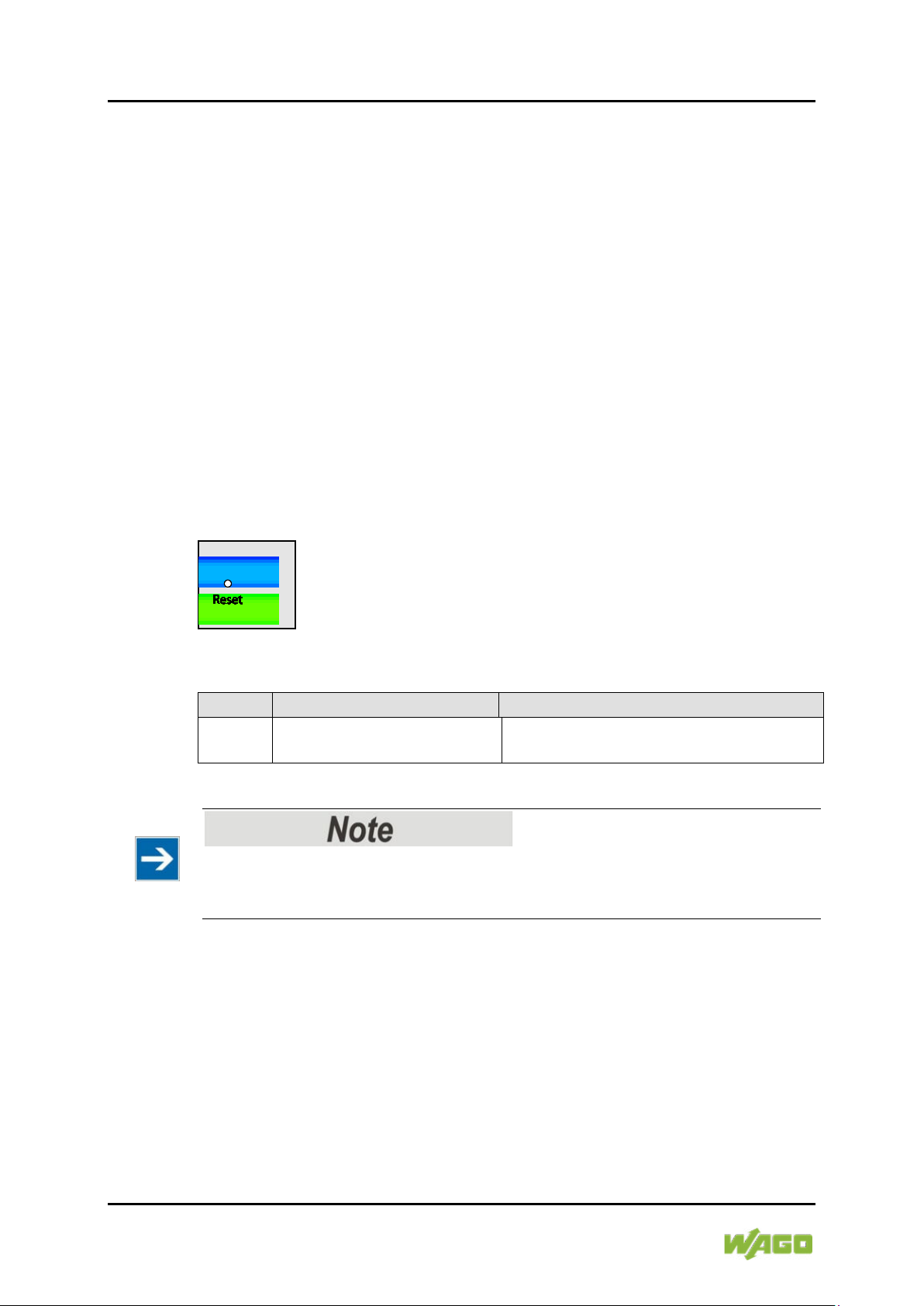
34 Device Description WAGO ETHERNET Accessories 852
Table 12: Legend for Figure “Reset Button”
Name
Status
Description
Reset
Press the Reset button for 2
seconds and release.
The system is restarted.
852-1505 8-Port 1000BASE-T;4-Slot 1000BASE-SX/LX; EXT;PoE
DIP switches let the user manually turn ON/OFF any port, the external alarm, or
the redundant power supply.
The DIP switch must be “ON” to activate the port alarm function. The default
setting is “OFF”.
The following is the recommended procedure for configuring and setting DIP
switches during initial installation:
1 Turn all DIP switches to “OFF”.
2 Install the industrial managed switch in your network.
3 Select the port(s) to be monitored or the alarm to be activated.
4 Set the DIP switch of the corresponding port to “ON”.
5 Turn the industrial managed switch ON.
4.4.2 Reset Button
Figure 8: Reset Button
Important Note!
Use a suitable object, e.g., ballpoint pen or straightened paper clip, to press the
Reset button.
Pos: 20.15 /D o kum entat io n all ge mei n/Gli ed eru ngsel e ment e/---Sei ten wec hs el--- @ 3\mod_1221108045078_0.docx @ 21810 @ @ 1
Manual
Version 1.0.0

WAGO ETHERNET Accessories 852 Device Description 35
Table 13: Legend for Figure “Label”
No.
“Serial NO” Description
02
Firmware version
01
Hardware version
852-1505 8-Port 1000BASE-T;4-Slot 1000BASE-SX/LX; EXT;PoE
Pos: 20.16 /Ser ie 852 (ET HERNET -Zub ehör) /G erät eb esc hrei bung /Au kl eber/ Au fkle ber 85 2-150 5 @ 31\mod_1524819192545_21.docx @ 484094 @ 23 @ 1
4.5 Label
4.5.1 Hardware and Software Version
There is a label with the “MAC Address” and “Serial NO” on the back of the
industrial managed switch.
Figure 9: Label (Example)
Pos: 20.17 /D o kum entat io n all ge mei n/Gli ed eru ngsel e ment e/---Sei ten wec hs el--- @ 3\mod_1221108045078_0.docx @ 21810 @ @ 1
Manual
Version 1.0.0

36 Device Description WAGO ETHERNET Accessories 852
Table 14: Technical Data – Device Data
Width
Carrier rail mounting
50 mm
Height
Carrier rail mounting
120 mm (from the top edge of the
carrier rail)
Depth
Carrier rail mounting
162 mm
Weight
970 g
Degree of protection
IP30
Table 15: Technical Data – System Data
MAC table
Up to 16000 addresses
VLAN
Port based and tag based (4094 VIDs)
Jumbo Frame Size
10 kB
Wavelength optical fibers
Depends on SFP module
Maximum lengths
10/100/
Table 16: Technical Data – Power Supply
Supply voltage
DC 48 … 57 V
Power consumption, max.
18 W, 258 W mit 8 PoE+
852-1505 8-Port 1000BASE-T;4-Slot 1000BASE-SX/LX; EXT;PoE
Pos: 20.18 / All e S erie n (Al lge mei ne M o dule) /Üb ersc hri ft en/E ben e 2/T ec hnisc h e Dat en - Über schr ift 2 @ 3\mod_1232967587687_21.docx @ 26924 @ 2 @ 1
4.6 Technical Data
Pos: 20.19 /Ser ie 852 (ET HERNET -Zub ehör) /G erät eb esc hrei bung /T echni sc he D ate n/T ech nisc he D ate n 85 2-1 505 @ 31\ mod_1524729496504_21.docx @ 483742 @ 33333 @ 1
4.6.1 Device Data
4.6.2 System Data
4.6.3 Power Supply
1000BASE-TX: 100 m;
Fiber optic: 2 km to 80 km
RS-232: 15 m
Manual
Version 1.0.0

WAGO ETHERNET Accessories 852 Device Description 37
Table 17: Technical Data – Communication
Ports
8 x 10/100/1000BASE-T with PoE+;
1 x RS-232 (RJ-45)
Standards
IEEE 802.3 10BASE-T
Protection Switching (ERPS)
Topology
Ring
Table 18: Technical Data ‒ Environmental Conditions
Surrounding air temperature, operation
-40 °C … +70 °C
Surrounding air temperature, storage
-40 °C … +80 °C
Relative humidity (without
condensation)
95 %
Vibration resistance
Acc. IEC 60068-2-6
Shock resistance
Acc. IEC 60068-2-27
EMC-1 immunity to interference
Acc. EN 61000-6-2
EMC-1 Emission of interference
Acc. EN 61000-6-4
852-1505 8-Port 1000BASE-T;4-Slot 1000BASE-SX/LX; EXT;PoE
4.6.4 Communication
IEEE 802.3u 100 BASE-TX
IEEE 802.3ab 1000BASE-T
IEEE 802.3z 1000BASE-SX/-LX
IEEE 802.3ad Port Trunk with LACP
IEEE 802.3x Flow Control
IEEE 802.1D Spanning Tree Protocol
(STP)
IEEE 802.1w Rapid Spanning Tree
Protocol (RSTP)
IEEE 802.1s Multiple Spanning Tree
Protocol (MSTP)
IEEE 802.1Q VLAN Tagging
IEEE 802.1p Prioritization
IEEE 802.1X Port Authentication
IEEE 802.1AB Link Layer Discovery
Protocol (LLDP)
IEEE 802.3ad Port Trunk with LACP
IEEE 1588v2 Precision Time Protocol
(PTP)
IEEE 802.3af Power over Ethernet
(PoE)
IEEE 802.3at High Power over Ethernet
(PoE+)
ITU-T G8032v1/v2 Ethernet Ring
4.6.5 Environmental Conditions
Pos: 20.20 /D o kum entat io n all ge mei n/Gli ed eru ngsel e ment e/---Sei ten wec hs el--- @ 3\mod_1221108045078_0.docx @ 21810 @ @ 1
Manual
Version 1.0.0

38 Device Description WAGO ETHERNET Accessories 852
Conformity Marking
Ordinary
852-1505 8-Port 1000BASE-T;4-Slot 1000BASE-SX/LX; EXT;PoE
Pos: 20.21 / All e S erie n (Al lge mei ne M odul e)/Üb ersc hrift en/Eb ene 2/Z ulassu ngen - Ü bers chr ift 2 @ 3\mod_1224055364109_21.docx @ 24030 @ 2 @ 1
4.7 Approvals
Pos: 20.22 / Ser ie 852 ( ETH ER NET-Z ube hör)/ Gerät ebesc hreibu ng/Z ulass unge n/Zulas sung en WAGO- ETHERN ET-Z ubehör 85 2-xxxx Allge mein @ 16\mod_1380023597338_21.docx @ 132665 @ @ 1
The following approvals have been granted for the WAGO ETHERNET
accessory product “ 8-Port 1000BASE-T;4-Slot 1000BASE-SX/LX; EXT;PoE”
(852-1505):
Pos: 20.23 / Alle S erie n (Al lge mei ne M odul e) /Z ulass ung en/S ta ndar dz ulass u ngen /CE (K onfor mit äts kenn zei chn ung ) @ 3\mod_1224494777421_21.docx @ 24276 @ @ 1
Pos: 20.24 /D o kum entat io n all ge mei n/Gli ed eru ngsel e ment e/---Leerabsatz-(2Z)--- @ 3\mod_1224662755687_0.docx @ 24460 @ @ 1
Pos: 20.25 / Ser ie 852 ( ETH ER NET-Z ube hör)/ Gerät ebesc hreibu ng/Z ulass unge n/Zul. i n Vorber eitu ng WAGO- ETHERN ET-Zub ehör 85 2-xxxx Allge mein @ 1 9\mod_1400487395419_21.docx @ 154058 @ @ 1
The following approvals are pending for WAGO ETHERNET accessory products
“ 8-Port 1000BASE-T;4-Slot 1000BASE-SX/LX; EXT;PoE” (852-1505):
Pos: 20.26 / All e S erie n (Al lge mei ne M o dule) /Z ulass ung en/ Sta ndar dz ulass u ngen /cU Lus (UL 610 10-2-2 01) @ 2 5\mod_1456305700986_0.docx @ 202311 @ @ 1
Locations
Pos: 21 /Dokum entati on allg emei n/Gli ederung sele mente /---Seit enwec hsel--- @ 3\mod_1221108045078_0.docx @ 21810 @ @ 1
UL61010-2-201
Manual
Version 1.0.0

WAGO ETHERNET Accessories 852 Mounting 39
852-1505 8-Port 1000BASE-T;4-Slot 1000BASE-SX/LX; EXT;PoE
Pos: 22.1 /Al le Seri en ( Al lge mei ne Mo dul e)/Ü ber schr ift en/ Eb ene 1/M onti ere n - Ü bersc hrift 1 @ 3\mod_1225446744750_21.docx @ 24900 @ 1 @ 1
5 Mounting
Pos: 22.2 /Serie 852 (ETHERNET-Zubehör)/Montier en/M ontag eort 8 52-x30x @ 24\mod_1452256541388_21.docx @ 197891 @ 2 @ 1
5.1 Installation Site
The location selected to install the industrial managed switch may greatly affect
its performance. When selecting a site, we recommend considering the following
rules:
• Install the industrial managed switch at an appropriate place. See section
“Device Description” > … > “Technical Data“ for the acceptable
temperature and humidity operating ranges.
Pos: 22.3 /Serie 852 (ETHERNET-Zubehör)/Montier en/M onti eren 85 2-x30x @ 2 4\mod_1452258998917_21.docx @ 197895 @ 22 @ 1
Make sure that the heat output from the industrial managed switch and ventilation
around it is adequate. Do not place any heavy objects on the industrial managed
switch.
5.2 Installation on a Carrier Rail
The carrier rail must optimally support the EMC measures integrated into the
system and the shielding of the internal data bus connections.
Place the industrial managed switch onto the DIN rail from the top and snap it
into position.
5.3 Removal from Carrier ail
To remove the industrial managed switch from the carrier rail, insert a suitable
tool into the metal tab under the switch and deflect the metal tab downward.
You can then release the switch down from the carrier rail and remove it
upwards.
Pos: 23 /Dokum entati on allg emei n/Gli ederung sele mente /---Seit enwec hsel--- @ 3\ mod_1221108045078_0.docx @ 21810 @ @ 1
Manual
Version 1.0.0

40 Connect Devices WAGO ETHERNET Accessories 852
852-1505 8-Port 1000BASE-T;4-Slot 1000BASE-SX/LX; EXT;PoE
Pos: 24 /All e S eri en ( Allg emei n e Mod ule) /Ü ber schri fte n/ Ebe ne 1/ Ger äte ans chl ieß en - Ü bersc hrift 1 @ 3\mod_1234172889468_21.docx @ 27460 @ 1 @ 1
6 Connect Devices
Pos: 25.1 /Serie 852 (ETHERNET-Z ube hör )/A nsc hließ en/ Ansc hlus s S pan nung s vers orgu ng 852- 1505 @ 33\mod_1543485671142_21.docx @ 511760 @ 2 @ 1
6.1 Power Supply
The industrial managed switch uses direct current power supply for 48 … 57 V.
The primary and secondary network link is established via a 6-pin plug-in
connection located on the top of the industrial managed switch.
The female connector is composed of six connecting terminals and can be
inserted and removed easily by hand to connect to the 6-pin plug connector
located on the top of the switch.
The power supply for the industrial managed switch automatically adjusts to the
local power source and can also be switched On if no or not all patch cables are
connected.
1 Check whether the power LED on the front lights up when the device is
switched ON. If not, check that the power cable is correctly and securely
plugged in.
2 If a secondary power supply is connected, the RPS LED lights up.
3 PWR +/- conductors:
To connect or disconnect the conductors, actuate the spring in the female
connector directly using a screwdriver or an operating tool and insert or
remove the conductor.
4 For the backup DC connection, follow the same procedure as above.
Attach power wires to the female connector (in the position marked “RPS
+/-”).
5 Plug the female connector into the male connector of the switch if it has not
already been plugged in.
6 Check whether the power LED on the top of the device lights up when
power is supplied to the device. If not, check to ensure that the power cable
is plugged in correctly and fits securely.
Pos: 25.2 /Dokumentation allgemein/Glieder ungselemente/---Seitenwechsel--- @ 3\mod_1221108045078_0.docx @ 21810 @ @ 1
Manual
Version 1.0.0

WAGO ETHERNET Accessories 852 Connect Devices 41
852-1505 8-Port 1000BASE-T;4-Slot 1000BASE-SX/LX; EXT;PoE
Pos: null /Seri e 852 (ETH ERNE T-Zub ehör )/ Ansc hli eße n/A nsc hluss Al arm 85 2-150 5 @ 33\mod_1543486334380_21.docx @ 511899 @ 2 @ 1
6.2 External Alarm Contact Port
The industrial managed switch has an alarm contact connection on the top panel.
For detailed instructions on how to connect the alarm contact power wires to the
two ALM contacts of the 6-pin female connector, please refer to section “Power
Supply (PWR/RPS)” (it is the same procedure).
You can connect the alarm circuit to any warning device already installed in the
user's control room or factory floor. When a fault occurs, the industrial switch
sends a signal through the alarm contact to activate the external alarm. The
alarm contact has two ports that form a fault circuit for connecting to alarm
systems.
An alarm is signaled in the following cases:
1 Port link failure (e.g., cable disconnected, device breakdown, etc.)
2 PWR/RPS:
a Power failure (power cord is disconnected, power supply malfunction,
etc.)
b Input power falls outside specification
(48 … 57 V)
3 Error in the Jet-Ring or ERPS-Ring
Pos: 25.4 /Serie 852 (ETHERNET-Zubehör)/Ansc hließ en/ Ansc hlus s K ons ol ena nschl us skab el 852-0 104, -0303, 1305 @ 3\mod_1222251499421_21.docx @ 22164 @ 2 @ 1
6.3 Console Port Cable Connection
The console port (RJ-45) provides the local management facility.
1. Insert the RJ-45 side of the (8 pin RJ-45 to DB9) cable into the RJ-45
console port on the Industrial Managed Switch and the other end into the
COM port of the computer.
2. Configure the Hyper Terminal settings as mentioned in chapter
“Configuration“ > … > “Console Port”.
For console port (8 pin RJ-45) pin assignment, please see in the chapter
“Appendix“ > …> “Console Port (RJ-45 to DB9)”.
Pos: 25.5 /Doku menta tion al lge mein/Gl ieder ungs elemente/---Seiten wechs el--- @ 3\mod_1221108045078_0.docx @ 21810 @ @ 1
Manual
Version 1.0.0

42 Connect Devices WAGO ETHERNET Accessories 852
852-1505 8-Port 1000BASE-T;4-Slot 1000BASE-SX/LX; EXT;PoE
Pos: 25.6 /Serie 852 (ETHERNET-Zubehör)/Ansc hließen /Ansc hlus s 1000B ase-SX /LX, Gl asf aserka bel 852- x30x @ 24\mod_1452260347709_21.docx @ 197927 @ 2 @ 1
6.4 1000Base-SX/LX Port, Fiber Optic
When connecting a fiber optic cable to a 1000Base-SX/LX port on the industrial
managed switch, make sure to use the right connector type (LC) and SFP
module.
There are various types of multi-mode, single mode or WDM SFP modules.
Follow the steps below to connect the fiber optic cable properly:
Rubber covers
Remove and safely store the rubber covers of the fiber optic port (LC).
If no fiber optic cable is connected, the rubber cover should be installed to protect
the fiber optics.
1 Insert the respective SFP modules.
2 Ensure that the fiber optic ports are clean. You can clean the cable
connectors by wiping them with a clean cloth or a cotton ball soaked with a
little ethanol. Dirty fiber optic cables affect the quality of the light transmitted
via the cable and leads to reduced performance at the port.
3 Connect one end of the fiber optic cable to the LC port of the industrial
managed switch and the other end to the fiber optic port of the other
device.
Proper connection of the fiber optic cable to the SFP module
For a proper connection, snap the connector of the fiber optic cable into the SFP
module audibly.
4 Check the respective port LED on the industrial managed switch that the
connection is established (see section “Device Description” > … > “Display
Elements”).
Pos: 25.7 /Dokumentation allgemein/Glieder ungselemente/---Seitenwechsel--- @ 3\mod_1221108045078_0.docx @ 21810 @ @ 1
Manual
Version 1.0.0

WAGO ETHERNET Accessories 852 Connect Devices 43
852-1505 8-Port 1000BASE-T;4-Slot 1000BASE-SX/LX; EXT;PoE
Pos: 25.8 /Serie 852 (ETHERNET-Z ubeh ör)/A nschli eßen/ Ansc hluss 10/ 100/ 1000 Base-T-Ports 852-1305 @ 27 \mod_1467291554066_21.docx @ 215659 @ 2 @ 1
6.5 10/100/1000BASE-T Ports
The 10/100/1000BASE-T ports (RJ-45 ETHERNET ports) of the industrial
managed switch support both autosensing and autonegotiation.
1 Connect one end of the twisted pair cable of the type Category 3/4/5/5e to
an available RJ-45 port on the industrial managed switch and the other end
to the port of the selected network node.
2 Check the respective port LED on the industrial managed switch that the
connection is established.
(see section “Display Elements” > … > “Port LEDs”).
Pos: 26 /Dokum entati on allg emei n/Gli ederung sele mente /---Seit enwec hsel--- @ 3\mod_1221108045078_0.docx @ 21810 @ @ 1
Manual
Version 1.0.0

44 Enhanced Features WAGO ETHERNET Accessories 852
852-1505 8-Port 1000BASE-T;4-Slot 1000BASE-SX/LX; EXT;PoE
Pos: 27.1 /Serie 852 (ETHERNET-Zubehör)/Erwei tert e F un ktion en/F un ktio nsbes chr ei bung - Ü bers chri ft 1 @ 3\mod_1222693989093_21.docx @ 22350 @ 1 @ 1
7 Enhanced Features
Pos: 27.2 /Serie 852 (ETHERNET-Zubehör)/Erwei tert e Fu nktion en/F unktio nsbes chr eibung 8 52-1505 @ 31\mod_1525242348732_21.doc x @ 484688 @ 23333443323445534434445533333344333332345445333233334323433 @ 1
7.1 Basic Settings
7.1.1 Jumbo Frame
“Jumbo Frames” are ETHERNET frames with a size of more than 1518 bytes.
Jumbo frames can increase data transmission efficiency in a network. The bigger
the “Jumbo Frame,” the better the network performance is.
“Jumbo Frame” settings
The size setting for the “Jumbo Frames” applies to each port of the switch.
All connected network subscribers must support the same “Jumbo Frame” size.
Data packets that are larger than the “Jumbo Frame” setting are rejected by the
corresponding network subscribers.
7.1.2 SNTP
SNTP (“Simple Network Time Protocol”) is a protocol for synchronizing clocks in
computer systems. It is a less complex implementation of an NTP (“Network Time
Protocol”).
SNTP uses UTC – “Coordinated Universal Time” (French: “Temps Universel
Coordonné”). No information on time zones or daylight savings time is
transmitted. This information falls outside the protocol range and must be
obtained separately.
The SNTP port is 123.
Note!
1. The SNTP server always replies the current UTC time.
2. If the switch receives the SNTP reply time, it adjusts the time to the time
zone configuration and configures the time for the switch accordingly.
3. If the time server’s IP address is not configured, the switch does not send
an SNTP request packet.
4. If the switch does not receive an SNTP reply packet, it repeats the
challenge indefinitely every ten seconds.
5. If the switch receives an SNTP reply, it repeats the time request from the
NTP server every hour.
6. If the time zone and NTP server changes, the switch repeats the request
process.
7. No default SNTP server.
Manual
Version 1.0.0

WAGO ETHERNET Accessories 852 Enhanced Features 45
852-1505 8-Port 1000BASE-T;4-Slot 1000BASE-SX/LX; EXT;PoE
7.1.3 Management Host
The management host limits the number of hosts that the switch can manage.
There is no “Management Host” in the default settings. Any host can manage the
switch via Telnet or Web browser. If a user has configured one or more hosts,
only those hosts can manage the switch. The function allows users to configure
up to three entries for the management IPs.
7.1.4 MAC Management
The MAC address (“Media Access Control address”) is the unique hardware
number in a network.
Dynamische Adresse
When receiving frames, the switch records the source MAC address, receiving
port, VLAN and an “Age Time” in the address table. When the “Age Time” is
expired, the address entry is deleted from the address table.
Static Address
A static address set by the user does not include the “Age Time” and is not
deleted by the switch. The static address can only be deleted by a user. The
switch supports an address table of size up to 16 K.
Static and dynamic addresses share the same address table.
MAC Table
The “MAC Table” (MAC address table, also known as a filter database) shows
which frames are forwarded to the switch’s ports or filtered out.
If a device that belongs to a VLAN group sends a data packet that is forwarded to
a port on the switch, the MAC address of the device is read from the switch’s
MAC address table.
It also shows whether the MAC address is dynamic (assigned by the switch) or
static (set manually).
MAC Address Table
The switch uses the MAC address table to determine how to forward frames (see
figure below).
1. The switch checks a received frame and detects the port from which the
source MAC address originates.
2. The switch checks whether the frame’s destination MAC address matches
a source MAC address already detected in the MAC address table.
- If the switch already knows the port for this MAC address, it forwards the
frame to that port.
Manual
Version 1.0.0

46 Enhanced Features WAGO ETHERNET Accessories 852
852-1505 8-Port 1000BASE-T;4-Slot 1000BASE-SX/LX; EXT;PoE
- If the switch does not already know the port for this MAC address, it
forwards the frame to all ports. “Port Flooding” (forwarding too often to all
ports) can lead to network congestion.
- If the switch already knows the port for this MAC address and the
destination port is the same as the input port, the frame is filtered.
Figure 10: MAC Address Table Flowchart
7.1.4.1 Static MAC
Static MAC Addresses
A static MAC address is an address that has been manually entered in the MAC
address table. Static MAC addresses have no “Age Time.” When you set up rules
for static MAC addresses, you set static MAC addresses for a port. This may
reduce data transmission needs.
7.1.4.2 MAC Blacklist (Blacklisting)
This type of MAC address entry is configured manually. The switch ignores
packets that have MAC addresses contained in “Blackhole” MAC address entries
as their source or destination. “Blackhole” entries are configured to filter out
frames with specific source or destination MAC addresses.
Manual
Version 1.0.0

WAGO ETHERNET Accessories 852 Enhanced Features 47
852-1505 8-Port 1000BASE-T;4-Slot 1000BASE-SX/LX; EXT;PoE
7.1.5 Port Mirroring
Port mirroring is used on switches to send a copy of network packets
sent/received on one switch port or a range of switch ports to a network
monitoring connection on another switch port (Monitor Port).
Port mirroring is used in network systems that require monitoring of network
traffic, such as an IDS (“Intrusion Detection System”).
Port mirroring, together with an NTA (“Network Traffic Analyzer”), can help to
monitor network traffic. Users can monitor the selected ports (“Source Ports”) for
egress and/or ingress packets.
Source Mode
• “Ingress”: The incoming data packets are copied and forwarded to the
monitor port.
• “Egress”: The outgoing data packets are copied and forwarded to the
monitor port.
• Both: Both the incoming and the outgoing data packets are copied and
forwarded to the to the monitor port.
Important Note! -> Durch Hinweisüberschrift ersetzen!
1. The monitor port cannot be a trunk member port.
2. The monitor port cannot be an ingress or egress port.
3. If a port has been configured as a source port and the user configures the port
as a destination port, the port will be removed from the source ports
automatically.
7.1.6 Port Settings
Duplex Mode
A duplex communication system is a system composed of two connected devices
that can communicate with each other in both directions.
Manual
Version 1.0.0

48 Enhanced Features WAGO ETHERNET Accessories 852
852-1505 8-Port 1000BASE-T;4-Slot 1000BASE-SX/LX; EXT;PoE
Half-Duplex
A half-duplex system provides for communication in both directions, but only one
direction at a time (not simultaneously).
One device receives a signal and must wait for the other device to stop
transmitting before replying.
Figure 11: Half-Duplex Mode
Full-Duplex
A full-duplex system (also known as a double-duplex system) can communicate
simultaneously in both directions.
Fixed-line telephone networks, for example, are full-duplex, since both callers
can talk and listen at the same time.
Figure 12: Full-Duplex Mode
Manual
Version 1.0.0

WAGO ETHERNET Accessories 852 Enhanced Features 49
852-1505 8-Port 1000BASE-T;4-Slot 1000BASE-SX/LX; EXT;PoE
Loopback Test
In a “Loopback” test, a signal is sent from and then returned to a communication
device (“looped back”).
The test checks the proper functioning of the device and looks for faulty nodes in
the network.
For one type of “Loopback” test, a special plug (a so-called “wrap plug”) is
plugged into a communications device. The plug causes transmitted (output) data
to be returned as received (input) data, simulating a closed communication circuit
using a single computer.
Auto MDI/MDIX
MDI (“Medium-Dependent Interface”) is part of the transmitter/receiver unit
(transceiver) of a network device.
Auto-MDIX (“Automatic Medium-Dependent Interface Crossover”) is a network
technology integrated in the port that automatically detects the required network
cable type (“Straight-through” or “Crossover” cable) and configures the
connection accordingly.
“Crossover” cables are then unnecessary for connecting devices.
The interface corrects incorrect cabling automatically.
For Auto-MDIX to work properly, the speed must be set to “Auto” for the interface
and in the duplex settings.
Auto-Negotiation
Auto-negotiation is a method in which two interconnected ETHERNET network
ports (e.g., the network port of a PC and a port of a router, hub or switch that is
connected to it) independently negotiate and configure the maximum
transmission speed and the duplex process.
Auto-negotiation only applies to twisted-pair cables – not to WLAN, fiber optic or
coaxial cable connections.
If the port does not support auto-negotiation or turns off this feature, the switch
determines the connection speed by detecting the signal on the cable and using
half duplex mode.
If auto-negotiation is enabled on the switch, a port uses its pre-configured
settings for speed and duplex mode when establishing the connection.
This should ensure that the same settings have been made on the port, allowing
the connection to be established.
Manual
Version 1.0.0

50 Enhanced Features WAGO ETHERNET Accessories 852
852-1505 8-Port 1000BASE-T;4-Slot 1000BASE-SX/LX; EXT;PoE
Flow Control
“Flow Control” regulates the transmission of signals by adjusting them to the
bandwidth on the input port.
Higher data traffic on the port decreases the bandwidth and can overflow the
buffer memory, which can lead to packet and frame loss.
According to IEEE 802.3x, the switch uses “Flow Control” in full-duplex mode and
“Backpressure Flow Control” in half-duplex mode.
With flow control, the switch is used in full-duplex mode to send a pause signal to
the sending port, causing it to temporarily stop sending signals when the
receiving port memory buffers fill.
For “Backpressure Flow Control,” the switch sends a collision signal to the
sending port in half-duplex mode (mimicking a state of packet collision), causing
the sending port to temporarily stop sending signals and to resend the signals
later.
Support for “Force Mode”
1000 BASE-T does not support “Force Mode.”
Manual
Version 1.0.0

WAGO ETHERNET Accessories 852 Enhanced Features 51
Priority
0 1 2 3 4 5 6
7
Queue
2 0 1 3 4 5 6
7
852-1505 8-Port 1000BASE-T;4-Slot 1000BASE-SX/LX; EXT;PoE
7.2 Advanced Settings
7.2.1 Bandwidth Control
7.2.1.1 QoS
Each egress port can support up to eight “transmit queues.” Each transmit queue
contains a list specifying the packet transmission order. Every incoming frame is
forwarded to one of the eight egress transmit queues of the assigned egress port,
based on its priority. The egress port transmits packets from each of the eight
transmit queues according to a configurable sequence algorithm, which can be a
combination of SP (“Strict Priority”) and/or WRR (“Weighted Round Robin”).
Normally, networks operate on a best-effort delivery basis, i.e., all data traffic has
equal priority and an equal chance of being transmitted in a timely manner.
If congestion occurs, all data traffic has an equal chance of being dropped.
When configuring the QoS (“Quality of Service”) function, you can select a
specific data traffic, prioritize it according to its relative importance and use
congestion management and congestion avoidance techniques to give
preferential treatment.
Implementing QoS in a network improves network predictability and increases
bandwidth utilization.
The industrial managed switch supports “802.1p Priority Queuing.”
The switch has eight “Priority Queues.” These priority queues are numbered,
where Class 7 has the highest priority and Class 0 the lowest. The eight priority
classes specified in IEEE 802.1p (p0 to p7) are mapped to the switch’s priority
queues as follows:
The “Priority Scheduling” is implemented in “Priority Queues.” The switch
operates the four “Hardware Priority Queues” sequentially, where it starts with the
highest “Priority Queue” (3) and ends with the lowest (0). Each “Hardware
Queue” transmits all the packets in its buffer before the next lower priority is
allowed to transmit its packets. If the lowest “Hardware Priority Queue” has
transmitted all its packets, the highest starts again to transmit the packets that it
received in the meantime.
Manual
Version 1.0.0

52 Enhanced Features WAGO ETHERNET Accessories 852
6
6 2 42-1496
4
DA
SA
Type/length
Data
FCS
6 6 4
2
42-1496
4
DA
SA
802.1Q Tag
Type/length
Data
FCS
852-1505 8-Port 1000BASE-T;4-Slot 1000BASE-SX/LX; EXT;PoE
QoS Enhancement
You can configure the switch to prioritize data traffic even if the incoming packets
are not marked with “IEEE 802.1p Priority Tags” or change the existing◌ ׅ
“Priority
Tags” based on criteria you select. The switch allows you to choose one of the
following methods for assigning priority to incoming packets:
• 802.1p Tag Priority
- Assign priority to packets based on the packet’s “802.1p Tag Priority.”
• Port-based QoS
- Assign priority to packets based on the incoming port on the switch.
• DSCP-based QoS
- Assign priority to packets based on their DSCP (“Differentiated
Services Code Points”).
Note
Advanced QoS Methods
Advanced QoS methods only affect the internal “Priority Queue” mapping
for the switch. The switch does not modify the IEEE 802.1p value for the
egress frames.
You can choose one of these options above to alter the way incoming packets
are prioritized, or you can choose not to use any QoS extension setting on the
switch.
802.1p Priority
When the 802.1p priority mechanism is used, the packet is examined for the
presence of a valid “802.1p Priority Tag.” If it has a tag, the packet is assigned to
a configurable “Egress Queue” based on its priority value. The “Tag Priority” can
be assigned to any of the available “Queues.”
ETHERNET Packet
Manual
Version 1.0.0

WAGO ETHERNET Accessories 852 Enhanced Features 53
2 bytes
2 bytes
Tag Protocol Identifier (TPID)
Tag Control Information (TCI)
16 bits
3 bit
1 bit
12 bits
TPID (0x8100)
Priority
CFI
VID
852-1505 8-Port 1000BASE-T;4-Slot 1000BASE-SX/LX; EXT;PoE
802.1Q Tag:
• TPID (“Tag Protocol Identifier”)A 16-bit field is set to the value of 0x8100 to
identify the frame as an “IEEE 802.1Q Tag Frame.”
• TCI (“Tag Control Information”)
- PCP (“Priority Code Point”)
A 3-bit field that refers to the IEEE 802.1p priority. This indicates the
frame priority level from 0 (lowest) to 7 (highest), which can be used to
prioritize different classes of traffic (voice, video, data etc.).
- CFI (“Canonical Format Indicator”)
A 1-bit field. If the value of this field is 1, the MAC address is in noncanonical format. If the value is 0, the MAC address is in canonical
format. It is always set to 0 for ETHERNET switches. CFI is used for
compatibility between ETHERNET and “Token Ring” networks. If a
frame received at an ETHERNET port has a CFI of 1, the frame should
not be output to an untagged port.
- VID (“VLAN Identifier”)
A 12-bit field specifying the VLAN to which the frame belongs. A value
of 0 means that the frame does not belong to any VLAN; in this case,
the “802.1Q Tag” specifies only a priority and is referred to as a
“Priority Tag.” A hexadecimal value of 0xFFF is reserved for
implementation purposes. All other values may be used as “VLAN
Identifiers,” allowing support for up to 4094 VLANs. On “Bridges,”
VLAN 1 is often reserved for management.
Manual
Version 1.0.0

54 Enhanced Features WAGO ETHERNET Accessories 852
Table 19: Priority Levels
PCP
Network Priority
Traffic Characteristics
1
0 (lowest)
“Background”
0 1 “Best Effort”
2 2 “Excellent Effort”
3 3 “Critical Applications”
4 4 Video, < 100 ms latency
5 5 Video, < 10 ms latency
6 6 Internetwork Control
7
7 (highest)
Network Control
Version
IHL
Type of Service
Total Length
Marking
Flags
Fragment Offset
Time to Live
Protocol
Header Checksum
Source Address
Destination Address
Options
Padding
852-1505 8-Port 1000BASE-T;4-Slot 1000BASE-SX/LX; EXT;PoE
Priority Levels
PCP (“Priority Code Point”):
DiffServ (DSCP)
DiffServ (“Differentiated Services”) is a computer networking architecture that
specifies a simple, scalable and coarse-grained mechanism for managing
network traffic and providing QoS (“Quality of Service”) guarantees in modern IP
networks. DiffServ can, for example, be used to provide low-latency GS
(“Guaranteed Service”) to critical network traffic such as voice or video data while
providing simple “Best Effort” traffic guarantees to non-critical services such as
Web traffic or file transfers.
DSCP (“Differentiated Services Code Point”) is a 6-bit field in the header of IP
packets for packet classification purposes. DSCP replaces the outdated IP
precedence, a 3-bit field in the “Type of Service” byte of the IP header originally
used to classify and prioritize types of traffic.
When using the DiffServ priority mechanism, a packet is classified based on the
DSCP field in the IP header. If the tag is present, the packet is assigned to a
programmable “Egress Queue” based on the value of its “Tagged Priority.” The
“Tagged Priority” can be assigned to any available “Queue.”
Example Internet Data Packet Header
“Type of Service” in the IP header: 8-bit
Manual
Version 1.0.0
The “Type of Service” field provides an indication of the abstract parameters of
the “Quality of Service” desired. These parameters are used to guide the manual

WAGO ETHERNET Accessories 852 Enhanced Features 55
Bits 0 … 2
Precedence.
Bit 3
0 = Normal delay,
1 = Low delay.
Bit 4
0 = Normal throughput,
1 = High throughput.
Bit 5
0 = Normal reliability,
1 = High reliability.
Bits 6 … 7
Reserved for future use.
852-1505 8-Port 1000BASE-T;4-Slot 1000BASE-SX/LX; EXT;PoE
selection of the actual service parameters when a data packet is to be
transmitted through a particular network. Several networks offer service
precedence, which treats high precedence traffic as more important than other
traffic (generally by accepting only traffic above certain precedence level at high
load times). The most favorable choice is a compromise between low delay, high
reliability and high throughput.
0 1 2 3 4 5 6 7 0 1 2 3
4 5 6 7
+-----+-----+-----+-----+-----+-----+-----+-----+
| PRECEDENCE | D | T | R | 0 | 0 |
+-----+-----+-----+-----+-----+-----+-----+-----+
Manual
Version 1.0.0

56 Enhanced Features WAGO ETHERNET Accessories 852
DSCP
Priority
DSCP
Priority
DSCP
Priority
0 0 1 0 2 0 …
60 0 61 0 62
0
62 0
852-1505 8-Port 1000BASE-T;4-Slot 1000BASE-SX/LX; EXT;PoE
Precedence
111 – Network Control
110 – Internetwork Control
101 – CRITIC/ECP
100 – Flash Override
011 – Flash
010 – Immediate
001 – Priority
000 – Routine
Specifying the Delay, Throughput and Reliability parameters can increase the
service cost. In many networks, giving preference to one parameter entails a
disadvantage for another. Except for very unusual cases, at most two of these
three parameters should be specified.
“Type of Service” is used to specify the type of processing of the data packet
while it is transmitted through a network. Example mappings of the “Internet Type
of Service” to the actual service provided in networks, such as AUTODIN II,
ARPANET, SATNET and PRNET, are specified in “Service Mappings.”
The Network Control precedence designation should only be used within a
network. The actual use and control of that designation depends on the
respective network. The Internetwork Control designation should only be
changed by the initiators of the gateway control.
If these precedence designations apply to a specific network, it is the
responsibility of that network to control the access to and use of those
designations.
Example:
IP Header
DSCP=50 -> 45 C8 …
Manual
Version 1.0.0

WAGO ETHERNET Accessories 852 Enhanced Features 57
852-1505 8-Port 1000BASE-T;4-Slot 1000BASE-SX/LX; EXT;PoE
Queuing Algorithms
“Queuing Algorithms” can be used to maintain separate “queues” for packets,
which can originate from any single source or any data flow, thus preventing one
source from monopolizing the bandwidth.
SPQ
With SPQ (“Strict Priority Queuing”), the four “Hardware Priority Queues” are
processed sequentially – the highest priority (3) first and the lowest (0) last. Each
“Hardware Queue” transmits all the packets in its buffer before the next lower
priority queue is allowed to transmit its packets. If the lowest “Hardware Priority
Queue” has transmitted all its packets, the highest starts again to transmit the
packets that it received in the meantime.
WRR
RR (“Round Robin”) is a scheduling service that queues packets on a rotating
basis and is only activated when a port has more traffic than it can handle. A
limited amount of bandwidth is provided to a queue, irrespective of the incoming
traffic on that port. This “queue” then moves to the back of the list. The next
“queue” is given an equal amount of bandwidth and then moves to the end of the
list and so on until all “queues” have been processed. The entire process works
in a looping fashion until a “queue” is empty.
WRR (“Weighted Round Robin”) scheduling uses the same algorithm as “Round
Robin” scheduling, but services “queues” based on their priority and queue
weight (the number you configure in the “Weight Value” field) rather than a fixed
amount of bandwidth. WRR is activated only when a port has more traffic than it
can handle. Processing “queues” with higher weights takes precedence over
processing lower weight ones. This queuing mechanism is highly efficient in that
it divides the entire available bandwidth among the various “Traffic Queues” and
allocates it to the ones that have not yet been emptied.
DiffServ Function
DiffServ is disabled on the industrial managed switch.
If the DiffServ is disabled, the “802.1p Tag Priority” is used.
Manual
Version 1.0.0

58 Enhanced Features WAGO ETHERNET Accessories 852
852-1505 8-Port 1000BASE-T;4-Slot 1000BASE-SX/LX; EXT;PoE
7.2.1.2 Rate Limitation
7.2.1.2.1 Storm Control
A broadcast storm occurs when the network is overwhelmed with constant
broadcast or multicast traffic. Broadcast storms can eventually lead to a complete
loss of network connectivity as the packets proliferate.
“Storm Control” protects the switch bandwidth from packet flooding, including
broadcast packets, multicast packets and DLF (“Destination Lookup Failure”).
The Rate is a threshold that limits the total number of specific packet types. For
example, if the broadcast and multicast options are selected, the total number of
packets transmitted per second for these two types is not exceeded.
“Broadcast Storm Control” limits the number of broadcast, multicast and unknown
unicast (also referred to as “Destination Lookup Failure” or DLF) packets the
switch receives per second on the ports. If the maximum number of packets per
second is reached, all subsequent packets are discarded. Enable this function to
reduce the number of these packets in the network.
The “Storm Control” unit is 625 pps (packets per second).
7.2.1.2.2 Rate Limitation
The “Rate Limitation” is used to control the rate of traffic sent or received on a
network interface.
Manual
Version 1.0.0

WAGO ETHERNET Accessories 852 Enhanced Features 59
852-1505 8-Port 1000BASE-T;4-Slot 1000BASE-SX/LX; EXT;PoE
7.2.2 IGMP Snooping
“IGMP Snooping” (“Internet Group Management Protocol Snooping”) is used for
multicast data traffic. The switch can passively “snoop” on IGMP packets
transmitted between IP multicast routers/switches and IP multicast hosts to learn
the IP multicast group membership. “IGMP Snooping” allows a switch to detect
multicast groups without a user having to manually configure them.
It checks IGMP packets passing through it, reads the group registration
information and configures multicasting accordingly.
The switch forwards multicast traffic to its multicast destination groups (which it
has detected through “IGMP Snooping,” or which you have manually configured)
to ports that are members of those groups. “IGMP Snooping” generates no
additional network traffic, allowing you to significantly reduce multicast traffic
passing through the switch.
The switch can perform “IGMP Snooping” on up to 4094 VLANs. You can
configure the switch to automatically detect multicast group membership in all
VLANs. The switch then performs “IGMP Snooping” on the first VLANs that send
IGMP packets.
This is referred to as “Auto Mode.” Alternatively, you can specify the VLANs that
“IGMP Snooping” should be performed on. This is referred to as “Fixed Mode.” In
“Fixed Mode,” the switch does not detect multicast group membership of any
VLANs other than those explicitly added as an “IGMP Snooping” VLAN.
Immediate Leave
If you enable the “IGMP Immediate Leave” function, the switch immediately
deletes a port when it receives a “Leave Message” with IGMP Version 2 on that
port. You should use the “Immediate Leave” function only when there is a single
receiver present on every port in the VLAN (“Immediate Leave” is only supported
on IGMP Version 2 hosts).
The switch uses the “Immediate Leave” function with “IGMP Snooping” to remove
from the forwarding table an interface that sends a “Leave Message,” without the
switch having to send group-specific queries to the interface. The VLAN interface
is deleted from the multicast tree for the multicast group specified in the original
“Leave Message.” “Immediate Leave” ensures optimal bandwidth management
for all hosts in a switched network, even when multiple multicast groups are
simultaneously in use.
Manual
Version 1.0.0

60 Enhanced Features WAGO ETHERNET Accessories 852
852-1505 8-Port 1000BASE-T;4-Slot 1000BASE-SX/LX; EXT;PoE
Fast Leave
The switch allows you to configure a delay time. When the delay time has
expired, the switch deletes the interface from the multicast group.
Last Member Query Interval
The “Last Member Query Interval” is the maximum response time in groupspecific queries sent in response to “Leave Group” messages, and also indicates
the time between group-specific query messages.
Without Immediate Leave, when the switch receives an IGMP leave message
from a subscriber on a receiver port, it sends out an IGMP-specific query on that
port and waits for IGMP group membership reports. If no reports are received in a
configured time period, the receiver port is removed from multicast group
membership.
IGMP Querier
There is normally only one “Querier” per physical network. All multicast routers
start up as a “Querier” on each connected network. If a multicast router receives
a “Query Message” from a router with a lower IP address, it MUST become a
non-“Querier” in that network. If a router does not receive any “Query Messages”
from another router over a certain period of time (“Other Querier Present
Interval”), it assumes the role of “Querier.” Routers periodically (“Query Interval”)
send a “General Query” in all attached networks for which the router is the
“Querier” in order to solicit membership information. At startup, a router SHOULD
send “General Queries” (“Startup Query Count”) spaced closely together
(“Startup Query Interval”) to quickly and reliably determine membership
information. A “General Query” is addressed to an all-systems multicast group
(224.0.0.1), has a group address field value of 0 and has a maximum response
time of (“Query Response Interval”).
Manual
Version 1.0.0

WAGO ETHERNET Accessories 852 Enhanced Features 61
852-1505 8-Port 1000BASE-T;4-Slot 1000BASE-SX/LX; EXT;PoE
Port IGMP Querier Mode
• Auto
- The switch uses the port as an “IGMP Query Port” if the port receives
“IGMP Query” packets.
• Fixed
- The switch always uses the port(s) as “IGMP Query Port(s).” This
mode is used when connecting an IGMP multicast server to the port(s).
- The switch always forwards the client’s “Report/Leave” packets to the
port. Normally, the port is connected to an IGMP server.
• Edge
- The switch does not use the port as an “IGMP Query Port.”
- The “IGMP Query” packets received on this port are dropped.
Normally, the port is connected to an IGMP client.
Forwarding “IGMP Join/Leave” packets
The industrial managed switch will forward the “IGMP Join/Leave” packets to the
query port.
IGMP Proxy Snooping
The “IGMP Proxy Snooping” can reduce the number of “Reports” and “Leaves”
sent through an IGMP router.
Configurations
Users can enable/disable “IGMP Snooping” on the switch. This also applies to
specific VLANs. If “IGMP Snooping” on the switch is disabled, it is disabled on all
VLANs, even when enabled on some VLANs.
VLAN States
There are a global state and individual VLAN states.
If the global state is disabled, “IGMP Snooping” on the switch is disabled even if
individual VLAN states have been enabled.
If the global state is enabled for “IGMP Snooping,” the function must be
individually enabled by the user for specific VLANs.
Manual
Version 1.0.0

62 Enhanced Features WAGO ETHERNET Accessories 852
852-1505 8-Port 1000BASE-T;4-Slot 1000BASE-SX/LX; EXT;PoE
7.2.2.1 MVR
MVR (“Multicast VLAN Registration”), through which a media server can transmit
a multicast stream in an individual multicast VLAN and in which the clients
receiving the VLAN stream can be located in different VLANs. Clients in different
VLANs can join or leave the multicast group simply by sending an “IGMP Join
Message” or “IGMP Leave Message” to a receiver port. The receiver port
belonging to a multicast group can receive the multicast stream from the media
server. Without MVR support, the multicast stream from the media server and
subscriber would have to be in the same VLAN.
• Source ports: The stream’s source ports.
• Receiver ports: The client’s ports.
• Tagged ports: Configure the tagged ports with tags to designate them as
source ports or receiver ports.
MVR Mode
• Dynamic Mode
If we select the dynamic mode in the MVR settings, the IGMP report
message transmitted from the receiver port will be forwarded to a multicast
router through its source port. The multicast router can detect dynamically
which multicast groups are on which interface.
• Compatibility Mode
If we select the dynamic mode in the MVR settings, the IGMP report
message transmitted from the receiver port will not be transmitted to the
source ports of the multicast router. The multicast router must be statically
configured.
• Operating Mode
Join Operation
A subscriber sends an “IGMP Report Message” to the switch to join the
respective multicast. The next step depends on whether the “IGMP Report
Message” matches the multicast MAC address configured on the switch. If
it matches, the switch CPU modifies the hardware address table to include
this receiver port and VLAN as a forwarding destination of MVLAN.
• Leave Operation
A subscriber sends an “IGMP Leave Message” to the switch to leave the
multicast. The switch CPU sends an IGMP group-specific query to the
receiver port VLAN. If there is another subscriber in the VLAN, the
subscriber must respond within the maximum response time. If there is no
subscriber, the switch will remove this receiver port.
Manual
Version 1.0.0

WAGO ETHERNET Accessories 852 Enhanced Features 63
852-1505 8-Port 1000BASE-T;4-Slot 1000BASE-SX/LX; EXT;PoE
• Immediate Leave Operation
A subscriber sends an “IGMP Leave Message” to the switch to leave the
multicast. The subscribers do not need to wait for the switch CPU to send a
group-specific “IGMP Query” to the receiver port of the VLAN. The switch
will immediately remove this receiver port.
Figure 13: MOD without MVR
Figure 14: MOD Supports MVR
Default Configuration for a New MVR:
MVR VLAN information
VLAN ID: 2
Name: MVR2
Active: Enabled
Mode: Dynamic
Source port(s): None
Receiver port(s): None
Port(s) with tag: None
Manual
Version 1.0.0

64 Enhanced Features WAGO ETHERNET Accessories 852
852-1505 8-Port 1000BASE-T;4-Slot 1000BASE-SX/LX; EXT;PoE
The switch allows the user to create up to 250 groups.
The switch allows the user to create up to 16 MVRs.
• “IGMP Snooping” and MVR can be enabled independently.
• “IGMP Snooping” and MVR use the same IGMP timer.
• MVR can recognize IGMPv3 reports.
• Both the switch and the following group record types do not treat group
entries such as an IGMPv3 report as membership reports. The group
record types are “MODE_IS_INCLUDE,”
“CHANGE_TO_INCLUDE_MODE,” “ALLOW_NEW_SOURCES” and
“BLOCK_OLD_SOURCES.”
• Do not use group address X.0.0.1 for your multicast stream. The system
detects and logs the address 224.0.0.1 for the dynamic “Querier Port.”
The group address X.0.0.1 could cause a conflict with 224.0.0.1.
• The lower 23 bits of the 28-bit multicast IP address are mapped to the 23
bits of the available ETHERNET address space.
• When configuring the group address, the switch only compares the lower
23 bits.
• The CLI command “group 1 start-address 224.1.1.1 6” creates six groups.
That means that one IP corresponds to one group.
• The MVR name should be a combination of numbers and letters.
• The group name should be a combination of numbers and letters.
Manual
Version 1.0.0

WAGO ETHERNET Accessories 852 Enhanced Features 65
Table 20: Multicast Classes and Address Ranges
Class
Address Range
Support
Class A
1.0.0.1 to
126.255.255.254
Supports 16 million hosts on each of 127
networks.
Class B
128.1.0.1 to
191.255.255.254
Supports 65,000 hosts on each of 16,000
networks.
Class C
192.0.1.1 to
223.255.254.254
Supports 254 hosts on each of 2 million
networks.
Class D
224.0.0.0 to
239.255.255.255
Reserved for multicast groups.
Class E
240.0.0.0 to
254.255.255.254
Reserved for future use or research and
development purposes.
852-1505 8-Port 1000BASE-T;4-Slot 1000BASE-SX/LX; EXT;PoE
7.2.2.2 Multicast Address
A multicast address is associated with a group of interested receivers. According
to RFC 3171, addresses 224.0.0.0 to 239.255.255.255 (formerly Class D
addresses) are reserved as multicast addresses in IPv4.
The first octet (01) includes the broadcast/multicast bit. The lower 23 bits of the
28-bit multicast IP address are mapped to the 23 bits of the available
ETHERNET address space. This means that there is an ambiguity in delivering
packets. If two hosts on the same subnet each subscribe to different multicast
groups whose addresses differ only in the first five bits, ETHERNET packets for
both multicast groups are sent to both hosts, requiring the network software in
the hosts to discard the unnecessary packets.
Manual
Version 1.0.0

66 Enhanced Features WAGO ETHERNET Accessories 852
Table 21: IP Multicast Addresses
IP Multicast Address
Description
224.0.0.0
Base address (reserved)
224.0.0.1
“All Hosts Multicast” group that contains all systems on
the same network segment.
224.0.0.2
“All Routers Multicast” group that contains all routers on
the same network segment.
224.0.0.5
The “Open Shortest Path First” (OSPF protocol), the
to all OSPF routers on a network segment
224.0.0.6
The “OSPF AllDRouters” address. Used to send OSPF
network segment
224.0.0.9
The RIP (“Routing Information Protocol”) Version 2 of the
RIPv2-compatible routers on a network segment.
224.0.0.10
The EIGRP group address. Used to send EIGRP routing
information to all EIGRP routers on a network segment.
224.0.0.13
PIM Version 2 (“Protocol Independent Multicast”)
224.0.0.18
Virtual Router Redundancy Protocol
852-1505 8-Port 1000BASE-T;4-Slot 1000BASE-SX/LX; EXT;PoE
Figure 15: Multicast Address
“AllSPFRouters” address. Used to send “Hello Packets”
routing information to “OSPF Designated Routers” on a
group address. Used to send routing information to all
Manual
Version 1.0.0

WAGO ETHERNET Accessories 852 Enhanced Features 67
Table 21: IP Multicast Addresses
IP Multicast Address
Description
224.0.0.19 - 21
IS-IS over IP
224.0.0.22
IGMP Version 3 (“Internet Group Management Protocol”)
224.0.0.102
Hot Standby Router Protocol Version 2
224.0.0.251
Multicast DNS address
224.0.0.252
“Link-local Multicast Name Resolution” address
224.0.1.1
“Network Time Protocol” address
224.0.1.39
“Cisco Auto-RP-Announce” address
224.0.1.40
“Cisco Auto-RP-Discovery” address
224.0.1.41
“H.323 Gatekeeper Discovery” address
852-1505 8-Port 1000BASE-T;4-Slot 1000BASE-SX/LX; EXT;PoE
Manual
Version 1.0.0

68 Enhanced Features WAGO ETHERNET Accessories 852
TPID
User Priority
CFI
VLAN ID
2 bytes
3 bits
1 bit
12 bits
852-1505 8-Port 1000BASE-T;4-Slot 1000BASE-SX/LX; EXT;PoE
7.2.3 VLAN
A VLAN (“Virtual LAN”) is a group of hosts with a common set of requirements
that communicate as if they were attached to a broadcast domain, regardless of
their physical location. A VLAN has the same attributes as a physical LAN, but it
allows for end stations to be grouped together even if they are not located on the
same network switch. Networks can be reconfigured through software instead of
spatially separated devices.
VID (“VLAN-ID”) is the identification of a VLAN that is generally used by the IEEE
12
802.1Q standard. It has 12 bits and allows the identification of 4096 (2
Of the 4096 possible VIDs, VID 0 is used to identify “Priority Frames,” and value
4095 (FFF) is reserved, so the maximum possible number of VLAN
configurations is 4094.
A “Tagged VLAN” uses an explicit tag (VLAN ID) in the MAC header to identify
the VLAN membership of a frame across “Bridges” – they are not confined to the
switch on which they were created. VLANs can be created statically (manually by
users) or dynamically via the GVRP (“GARP VLAN Registration Protocol”). The
VLAN ID associates a frame with a specific VLAN and provides the information
that switches need in order to process the frame across the network. A tagged
frame is four bytes longer than an untagged frame and contains two bytes of
TPID (“Tag Protocol Identifier,” residing within the type/length field of the
“ETHERNET Frame”) and two bytes of TCI (“Tag Control Information,” which
starts after the source address field of the “ETHERNET Frame”).
) VLANs.
The CFI (“Canonical Format Indicator”) is a single-bit flag, always set to zero for
ETHERNET switches. If a frame received at an ETHERNET port has a CFI of 1,
the frame should not be output to an untagged port. The remaining 12 bits define
the VLAN ID, giving a possible maximum number of 4096 VLANs. Note that the
user priority and VLAN ID are independent of each other. A frame with VID
(VLAN Identifier) of null (0) is called a priority frame, meaning that only the priority
level is significant, and the default VID of the ingress port is used as the VID of
the frame. Of the 4096 possible VIDs, a VID of 0 is used to identify “Priority
Frames,” and value 4095 (FFF) is reserved, so the maximum possible number of
VLAN configurations is 4094.
Manual
Version 1.0.0

WAGO ETHERNET Accessories 852 Enhanced Features 69
852-1505 8-Port 1000BASE-T;4-Slot 1000BASE-SX/LX; EXT;PoE
• Forwarded Tagged and Untagged Frames
Each port on the switch is capable of forwarding tagged and untagged frames.
When a frame is forwarded from an 802.1Q VLAN-aware switch to an 802.1Q
VLAN-unaware switch, the switch first decides where to forward the frame and
then strips off the VLAN tag. When a frame is forwarded from an 802.1Q VLANunaware switch to an 802.1Q VLAN-aware switch, the switch first decides where
to forward the frame and then inserts a VLAN tag reflecting the ingress port’s
default VID. The default PVID is “VLAN 1” for all ports, but this can be changed.
A broadcast frame (or a multicast frame for a multicast group that is known by the
system) is duplicated only on ports that are members of the VID (except the
ingress port itself), thus confining the broadcast to a specific domain.
• 802.1Q Port-Based VLAN
With port-based VLAN membership, the port is assigned to a specific VLAN
independent of the user or system attached to the port. This means all users
attached to the port should be subscribers of the same VLAN. The network
administrator typically performs the VLAN assignment. The port configuration is
static and cannot be automatically changed to another VLAN without manual
reconfiguration.
As with other VLAN approaches, the packets forwarded using this method are
not transmitted to other VLAN domains or networks. After a port has been
assigned to a VLAN, the port cannot send to or receive from devices in another
VLAN without the intervention of a Layer 3 device.
The device that is attached to the port likely has no understanding that a VLAN
exists. The device simply knows that it is part of a subnet and should be able to
talk to all other network subscribers by simply sending information via the cable
connection. The switch is responsible for identifying information that came from a
specific VLAN and for ensuring that the information gets to all other subscribers
of the VLAN. The switch is also responsible for ensuring that ports in a different
VLAN do not receive the information.
This approach is quite simple, fast and easy to manage, because there are no
complex lookup tables required for VLAN segmentation. If the “Port-to-VLAN”
connection is designed with an application-specific integrated circuit (ASIC),
performance is very good. An ASIC allows “Port-to-VLAN” mapping at the
hardware level.
7.2.3.1 Port Isolation
Port isolation is a port-based virtual LAN feature. It partitions the switching ports
into virtual private domains designated on a per port basis. Data switching
outside of the switch’s private domain is not allowed. The VLAN tag information
of the packets is ignored.
This feature is a per-port setting to configure the egress port(s) for the specific
port to forward its received packets. If the CPU port (port 0) is not an egress port
for a specific port, the host connected to the specific port cannot manage the
switch.
Manual
Version 1.0.0

70 Enhanced Features WAGO ETHERNET Accessories 852
852-1505 8-Port 1000BASE-T;4-Slot 1000BASE-SX/LX; EXT;PoE
If you wish to allow two subscriber ports to talk to each other, you must define the
egress port for both ports. CPU refers to the switch’s management port. By
default, it forms a VLAN with all ETHERNET ports. If it does not form a VLAN
with a specific port, then the switch cannot be managed from that port.
Manual
Version 1.0.0

WAGO ETHERNET Accessories 852 Enhanced Features 71
852-1505 8-Port 1000BASE-T;4-Slot 1000BASE-SX/LX; EXT;PoE
7.2.3.2 GARP/GVRP
GARP (“Generic Attribute Registration Protocol“) and GVRP (“GARP VLAN
Registration Protocol” or “Generic VLAN Registration Protocol”) are industry-
standard protocols described in IEEE 802.1p. GVRP is a GARP application that
provides 802.1Q-compliant “VLAN Pruning” and dynamic VLAN creation on
“802.1Q Trunk Ports.”
With GVRP, the switch can exchange VLAN configuration information with other
GVRP switches, prune unnecessary broadcast and unknown unicast traffic and
dynamically create and manage VLANs on switches that are connected through
“802.1Q Trunk Ports.”
GVRP makes use of GID (“Group Identification”) and GIP, which provide the
common “State Machine Descriptions” and the common information propagation
mechanisms defined for use in GARP-based applications. GVRP runs only on
“802.1Q Trunk Links.” GVRP prunes “Trunk Links” so that only active VLANs are
transmitted across trunk connections. GVRP waits to hear join messages from
the switches before adding a VLAN to the trunk. GVRP updates and hold timers
can be altered. GVRP ports run in various modes to control how they prune
VLANs. GVRP can be configured to dynamically add and manage VLANS in the
VLAN database for “Trunking” purposes.
In other words, GVRP allows the propagation of VLAN information from device to
device. With GVRP, a single switch is manually configured for all VLANs required
for the network, and all other switches on the network detect these VLANs
dynamically. End nodes can be plugged into any switch and connected to the
required VLAN. For end nodes to make use of GVRP, they need GVRP-aware
network interface cards (NICs). The GVRP-aware NIC is configured with the
desired VLAN or VLANs and then connected to a GVRP-enabled switch. The
NIC communicates with the switch once connectivity is established between the
NIC and switch.
Registration Mode:
• Normal
The “normal” registration mode allows dynamic creation (if dynamic VLAN
creation is enabled), registration and deregistration of VLANs on the trunk
port. “Normal” mode is the default setting.
• Forbidden
The “forbidden” registration mode deregisters all VLANs (except VLAN 1)
and prevents further creation or registration of VLANs on the trunk port.
Manual
Version 1.0.0

72 Enhanced Features WAGO ETHERNET Accessories 852
852-1505 8-Port 1000BASE-T;4-Slot 1000BASE-SX/LX; EXT;PoE
• Fixed
The “fixed” registration mode allows manual creation and registration of
VLANs, prevents VLAN deregistration and registers all known VLANs on
other ports on the trunk port. (The same applies to the static VLAN.)
GVRP Timer:
• Join Timer
The “Join Timer” specifies the maximum time in milliseconds that interface
waits before sending VLAN messages.
• Leave Timer
The “Leave Timer” specifies the maximum time in milliseconds an interface
waits after receiving a “Leave Message” before the interface leaves the
VLAN specified in the message.
• Leaveall Timer
The “Leaveall Timer” specifies the interval in milliseconds at which
“Leaveall Messages” are sent on interfaces. “Leaveall Messages” help to
update GVRP VLAN subscriber information in the network.
Manual
Version 1.0.0

WAGO ETHERNET Accessories 852 Enhanced Features 73
852-1505 8-Port 1000BASE-T;4-Slot 1000BASE-SX/LX; EXT;PoE
7.2.3.3 Q-in-Q
“Q-in-Q Tunneling” is also known as “VLAN Stacking.” This uses 802.1Q double
tagging technology. Q-in-Q is used by ISPs (Internet Service Providers) that need
TLSs (“Transparent LAN Services”) and that have their own VLANs, independent
of customer VLANs. Normally, each service provider VLAN interconnects a group
of sites belonging to a customer. However, a service provider VLAN could also
be shared by a set of customers sharing the same end points and QoS
requirements of the VLAN. “Double Tagging” is considered to be a relatively
simple way of implementing a transparent LAN. This is accomplished by
encapsulating “ETHERNET Frames.” A second or outer VLAN tag is inserted into
the “ETHERNET Frames” sent over the ingress PE (“Provider Edge”). This VLAN
tag corresponds to the VLAN of the service provider. If the frame reaches the
destination PE, the service provider VLAN opens. The destination address of the
encapsulated frame and VLAN ID are used for other L2 decisions, similar to an
“ETHERNET Frame” that arrives from a physical ETHERNET port. The service
provider VLAN tag determines the membership in the VPLS (“Virtual Private LAN
Service”). Double tagging aggregates multiple VLANs within another VLAN and
allows a private dedicated ETHERNET connection between customers who want
to reach their subnet transparently across multiple networks. Service providers
can create their own VLANs without coming in contact with customer VLANs via
“Double Tagging.” This allows customers to connect to ISPs and ASPs
(“Application Service Providers”).
The ports that are connected to the service provider VLANs are called tunnel
ports, and the ports that are connected to the customer VLANs are called access
(subscriber/customer) ports. If a port is configured as tunnel port, all outgoing
packets on this port are transmitted with an SPVLAN tag (SPVID and 1p priority).
The incoming packet can have two tags (SPVLAN + CVLAN), one tag (SPVLAN
or CVLAN) or no tag. In all cases, the packet is sent out with a SPVLAN tag. If a
port is configured as an access port, the incoming traffic can only have a CVLAN
tag (CVID and 1p priority) or no tag. Hence, all the packets sent from access
ports are untagged or single tagged (CVLAN). If a port is configured as a normal
port, it ignores “Double Tagging Frames.”
Manual
Version 1.0.0

74 Enhanced Features WAGO ETHERNET Accessories 852
TPID
Priority
VID
Untagged frame
DA
Len or
Etype
Data
FCS
Single-tagged
frame
DA
SA
TPID
P
VID
Len or
Etype
Data
FCS
Double-tagged
DA
SA
Tunnel
P
VID
TPID
P
VID
Len or
Data
FCS
DA
Destination Address
SA
Source Address
Tunnel TPID
“Tag Protocol Identifier” added to a “Tunnel Port”
VID
VLAN ID
Len or Etype
Length or ETHERNET frame type
Data
Frame data
FCS
Frame Check Sequence (checksum field)
852-1505 8-Port 1000BASE-T;4-Slot 1000BASE-SX/LX; EXT;PoE
Double Tagging Format
A VLAN tag (service provider “VLAN Stacking” or customer IEEE 802.1Q)
consists of the following three fields:
TPID
TPID (“Tag Protocol Identifier”) is a standard ETHERNET code identifying the
frame and indicating whether the frame contains IEEE 802.1Q tag information.
The value of this field is 0x8100 as described in IEEE 802.1Q. Other providers
may use a different value, such as 0x9100.
“Tunnel TPID” is the “VLAN Stacking” tag type that the switch adds to the
outgoing frames sent through a tunnel port of the service provider’s PE devices.
Priority
The priority relates to the IEEE 802.1p standard that allows the service provider
to prioritize traffic based on the class of service (CoS) the customer has paid for.
“0” is the lowest priority level and “7” is the highest.
VID
VID (“VLAN ID”). SP VID is the VID for the second or outer VLAN tag (of the
service provider). CVID is the VID for the first or inner VLAN tag (of the
customer).
The frame formats for an untagged “ETHERNET Frame,” a single-tagged
802.1Q frame (customer) and a double-tagged 802.1Q frame (service provider)
are shown as follows.
frame
TPID
Etype
VLAN Stacking Port Roles
For “VLAN Stacking,” each port can have one of three “roles”: Normal, “Access
Port” or “Tunnel Port.”
Manual
Version 1.0.0

WAGO ETHERNET Accessories 852 Enhanced Features 75
852-1505 8-Port 1000BASE-T;4-Slot 1000BASE-SX/LX; EXT;PoE
• Select “normal” for normal (no “VLAN Stacking”) IEEE 802.1Q frame
switching.
• Select “Access Port” for ingress ports on PE devices of the service
provider. The incoming frame is treated as “untagged,” so a second VLAN
tag (outer VLAN tag) can be added.
• Select “Tunnel Port” for egress ports at the edge of the service provider’s
network. All VLANs belonging to a customer can be aggregated into a
single service provider’s VLAN (using the outer VLAN tag defined by SP
VID).
Q-in-Q Configuration
For the double-tagged frames to switch correctly, users have to configure a
service provider’s VLAN (SPVLAN) on the Q-in-Q switch. The double-tagged
frames can then be switched according to the SP VID. The SPVLAN should
include all related “Tunnels” and “Access Ports.” Also, the tunnel ports have to be
configured as tagged ports and the access ports as untagged ports.
Manual
Version 1.0.0

76 Enhanced Features WAGO ETHERNET Accessories 852
852-1505 8-Port 1000BASE-T;4-Slot 1000BASE-SX/LX; EXT;PoE
7.2.3.3.1 Port-Based Q-in-Q
Q-in-Q encapsulation can be used to convert a single-tagged 802.1Q packet into
a double-tagged Q-in-Q packet. The Q-in-Q encapsulation can be based on port
or traffic. Port-based Q-in-Q can be used to encapsulate all incoming packets in a
port with the same SPVID outer tag. This mode is less flexible.
In the following example figure, both X and Y are Service Provider’s Network
(SPN) customers with VPN tunnels between their respective head offices and
branch offices. Both have an identical VLAN tag for their VLAN group. The
service provider can separate these two VLANs within its network by adding tag
100 to distinguish customer X and tag 200 to distinguish customer Y at PE device
A and then stripping those tags at PE device B as the data frames leave the
network.
Figure 16: Port-Based Q-in-Q
This example shows how to configure switch A with port 1 on the switch in order
to tag incoming frames with the service provider’s VID of 200 (ports connected to
customer X network) and configure port 7 to the service provider’s VID of 100
(ports connected to customer Y network). This example also shows how to set
the priority for port 1 to 3 and port 7 to 4.
Manual
Version 1.0.0

WAGO ETHERNET Accessories 852 Enhanced Features 77
852-1505 8-Port 1000BASE-T;4-Slot 1000BASE-SX/LX; EXT;PoE
7.2.3.3.2 Selective Q-in-Q
Traffic-based Q-in-Q is also called selective Q-in-Q. Selective Q-in-Q allows the
switch to add different outer VLAN tags to the incoming frames received on one
port according to their inner VLAN tags. In selective Q-in-Q mode, the switch
classifies the incoming traffic on a port based on the VLAN ID. When a user uses
different VLAN IDs for different services, traffic can be classified according to the
VLAN ID. Example: VLAN ID 100 for surfing the Internet on a PC, VLAN ID 200
for IPTV and VLAN ID 300 for VIP customers. After receiving user data, the
switch labels the traffic for surfing the Internet on a PC with 500 as a SPVID outer
tag, IPTV with 600 and VIP customers with 700.
This following example shows how to configure port 3 on the switch to tag
incoming frames with the different VIDs and priorities of the service provider.
Figure 17: Configuration Example
Manual
Version 1.0.0

78 Enhanced Features WAGO ETHERNET Accessories 852
852-1505 8-Port 1000BASE-T;4-Slot 1000BASE-SX/LX; EXT;PoE
7.2.4 DHCP Relay
Because the “DHCPDISCOVER” message is a broadcast message, and
broadcasts only cross other segments when they are explicitly routed, you might
have to configure a “DHCP Relay Agent” on the router interface so that all
“DHCPDISCOVER” messages can be forwarded to your DHCP server.
Alternatively, you can configure the router to forward DHCP messages and
BOOTP message. In a routed network, you would need “DHCP Relay Agents” if
you plan to implement only one DHCP server.
The “DHCP Relay,” which is either a host or an IP router, waits for DHCP client
messages to be broadcast on a subnet and then forwards those DHCP
messages directly to a configured DHCP server. The DHCP server sends DHCP
response messages directly back to the “DHCP Relay Agent,” which then
forwards them to the DHCP client. The DHCP administrator uses “DHCP Relay
Agents” to centralize DHCP servers, avoiding the need for a DHCP server on
each subnet.
Most of the time in small networks, DHCP uses broadcasts, but there are some
circumstances where unicast addresses are used. This can be the case when
networks have a single DHCP server that provides IP addresses for multiple
subnets. A router for such a subnet receives the DHCP broadcasts, converts
them to unicast (with a MAC/IP destination address of the configured DHCP
server, MAC/IP source address of the router itself). The GIADDR field on the
main DHCP page contains the IP address of the interface on the router on which
it received the DHCP request. The DHCP server uses the GIADDR field to
identify the subnet for the device and selects an IP address from the correct pool.
After that, the DHCP server sends the “DHCP OFFER” back to the router via
unicast, which then converts it back to a broadcast and sends it out to the correct
subnet containing the device that requested an address.
Configurations
A user can enable/disable the “DHCP Relay” on the switch. It can also be
enabled/disabled on a specific VLAN. If “DHCP Relay” is disabled on the switch,
it is disabled on all VLANs, even if enabled for individual VLANs.
Applications
• Application 1 (via a router)
DHCP client 1 and DHCP client 2 are in different IP segments. However,
they receive the IP address from the same DHCP server.
Manual
Version 1.0.0

WAGO ETHERNET Accessories 852 Enhanced Features 79
852-1505 8-Port 1000BASE-T;4-Slot 1000BASE-SX/LX; EXT;PoE
Figure 18: Application 1 (via a Router)
• Application 2 (local in different VLANs)
DHCP client 1 and DHCP client 2 are in different VLANs. However, they
receive the IP address from the same DHCP server.
Figure 19: Application 2 (Local in Different VLANs)
VLAN 1: Port 1, 2 (Management VLAN)
VLAN 2: Port 3, 4
VLAN 3: Port 5, 6
VLAN 4: Port 7, 8
DHCP Server -> Port 1.
DHCP Client -> Port 2, 3, 4, 5, 6, 7, 8.
Result: Hosts connected to port 2, 3, 4, 5, 6, 7 and 8 receive an IP from
the DHCP server.
Note
DHCP Server Connection
The DHCP server must connect to the management VLAN member ports.
The “DHCP Relay” in the management VLAN must be enabled.
Manual
Version 1.0.0

80 Enhanced Features WAGO ETHERNET Accessories 852
852-1505 8-Port 1000BASE-T;4-Slot 1000BASE-SX/LX; EXT;PoE
7.2.5 DHCP Relay Option 82
“DHCP Option 82” (“DHCP Relay Agent Information Option”). Option 82 was
designed to allow a “DHCP Relay Agent” to insert circuit-specific information into
a request that is being forwarded to a DHCP server. Specifically, the option
works by setting two sub-options: “Circuit ID” and “Remote ID.”
“DHCP Option 82” operates on the basis of “DHCP Snooping” or/and “DHCP
Relay.”
The switch monitors the DHCP packets and appends some information under
“DHCPDISCOVER” and “DHCPREQUEST” packets. The switch deletes “DHCP
Option 82” from the “DHCPOFFER” and “DHCPACK” packets. The DHCP server
then assigns an IP domain to the client based on this information.
The maximum length for this information is 32 characters.
In residential, metropolitan ETHERNET-access environments, DHCP can
centrally manage the IP address assignments for a large number of subscribers.
If the “DHCP Option 82” function is enabled on the switch, a subscriber device is
identified by the switch port through which it connects to the network (in addition
to its MAC address). Multiple hosts on the subscriber LAN can be connected to
the same port on the switch and are uniquely identified.
If you enable “DHCP Snooping Information Option 82” on the switch, the
sequence of events is:
• The host (DHCP client) generates a DCHP request and broadcasts it on
the network.
• If the switch receives the DHCP request, it adds the “Option 82” information
to the packet. The information contains the switch MAC address (the
“Remote ID” sub-option), the “Port Identifier” and the “VLAN-Mod-PORT”
from which the packet is received (the “Circuit ID” sub-option).
• If the IP address of the “Relay Agent” has been configured, the switch adds
the IP address to the DHCP packet.
• The switch forwards the DHCP request that includes the Option 82 field to
the DHCP server.
• The DHCP server receives the packet. If the server is Option 82 capable, it
can use the “Remote ID,” “Circuit ID” or both to assign IP addresses and
implement policies, such as restricting the number of IP addresses that can
be assigned to a single “Remote ID” or “Circuit ID.” The DHCP server then
echoes the Option 82 field in the DHCP reply.
• The DHCP server forwards the reply to the switch as a unicast if the
request was relayed to the server by the switch. If the client and server are
on the same subnet, the server broadcasts the reply. The switch verifies
the Option 82 data originally entered by checking the “Remote ID” and
“Circuit ID” fields. The switch deletes the Option 82 field and forwards the
packet to the switch port that connects to the DHCP client that sent the
DHCP request.
Manual
Version 1.0.0

WAGO ETHERNET Accessories 852 Enhanced Features 81
Table 22: Option Frame Format
Code
Len
Agent Information Field
82
N
i1
i2
i3
i4 … iN
Table 23: Option Frame Format
Sub-Option
Len
Sub-Option Value
1
N
s1
s2
s3
s4 … sN
Table 24: Frame Format of the “Circuit ID” Sub-Option
Sub-Option
Type
Length
“Circuit ID”
Type
Length
VLAN
Module
Port
1 6 0 4 2 1 1
Table 25: Frame Format of the “Remote ID” Sub-Option
Sub-Option
Type
Length
“Circuit ID”
Type
Length
MAC Address
2 8 0
6
6
Table 26: Format of the “Circuit ID” Sub-Option
Code
Len
Sub-Option
Type
Length
Slot ID
Port ID
VLAN
ID
Information
0x52
0x0c
0x01
0x0a
0x01
0x01
0x0002
justin
852-1505 8-Port 1000BASE-T;4-Slot 1000BASE-SX/LX; EXT;PoE
Option Frame Format
The “Agent Information Field” consists of a sequence of SubOpt/Length/Value
tuples for each sub-option, encoded in the following manner:
DHCP Agent Sub-Option Description
Sub-Option Code
-------------------------- -------------------------------------
1 “Agent Circuit ID” sub-option
2 “Agent Remote ID” sub-option
Manual
Version 1.0.0

82 Enhanced Features WAGO ETHERNET Accessories 852
852-1505 8-Port 1000BASE-T;4-Slot 1000BASE-SX/LX; EXT;PoE
7.2.6 Dual Ring
The “Dual Ring” function can be used to connect two neighboring rings to each
other on a switch without the need for additional ports or cables. This
configuration reduces the total number of required ports and the wiring costs,
because no additional wiring is required.
Figure 20: Dual Ring Switch ABC
Figure 21: Dual Ring Switch AB
Manual
Version 1.0.0

WAGO ETHERNET Accessories 852 Enhanced Features 83
852-1505 8-Port 1000BASE-T;4-Slot 1000BASE-SX/LX; EXT;PoE
7.2.7 ERPS
The ERPS (“ETHERNET Ring Protection Switching”) function implements a
protection switching mechanism for ETHERNET layer ring topologies according
to ITU-T standard G.8032. The ERP (“ETHERNET Ring Protection”) protects
ETHERNET traffic in a ring topology and ensures that no loops can arise within
the ring in the ETHERNET layer. Looping is prevented by blocking traffic on
either a predetermined link or a failed link.
The ETHERNET ring protection functionality includes the following:
• Loop avoidance
• Use of learning, forwarding and filter database (FDB) mechanisms
Loop avoidance in an Ethernet ring is achieved by guaranteeing that, at any time,
traffic may flow on all but one of the ring links. This particular ring link serves as a
reserve connection and is called an RPL (“Ring Protection Link”). In normal
operation, it is blocked and not used for service traffic. A specific ETHERNET ring
node, the “RPL Owner” node, is responsible for blocking traffic at one end of the
RPL. Under an ETHERNET ring failure condition, the “RPL Owner” node is
responsible for unblocking its end of the RPL, unless the RPL has failed, allowing
the RPL to be used for traffic. The ETHERNET ring node adjacent to the RPL,
the “RPL Neighbor” node, may also participate in blocking or unblocking its end
of the RPL.
The ETHERNET rings can support a multi-ring/ladder network that consists of
ETHERNET rings linked through one or more interconnection points. The
protection switching mechanisms and protocol defined in this recommendation
can be used for a multi-ring/ladder network under the following conditions:
• R-APS channels are not shared across ETHERNET ring connections;
• On each ring port, all traffic channels and all R-APS channels are controlled
(e.g., for blocking or flushing) by the ETHERNET ring protection control
process (ERP control process) of only one ETHERNET ring;
• Each main ring or subring has its own RPL.
In an ETHERNET ring without congestion, with all ETHERNET ring nodes in the
idle state (i.e., no detected failure, no active automatic or external command and
receiving only R-APS (NR, RB) messages) and with less than 1,200 km of ring
fiber circumference and fewer than 16 ETHERNET ring nodes, the switch
completion time (transfer time as defined in [ITU-T G.808.1]) for a failure on a
ring link should be less than 50 ms.
The ring protection architecture relies on the existence of an APS protocol to
coordinate ring protection actions in an ETHERNET ring.
The switch supports up to six rings.
Manual
Version 1.0.0

84 Enhanced Features WAGO ETHERNET Accessories 852
852-1505 8-Port 1000BASE-T;4-Slot 1000BASE-SX/LX; EXT;PoE
Guard Timer
All ring subscribers use a “Guard Timer.” It prevents a closed loop from forming
and prevents ring subscribers from using outdated R-APS messages. The
“Guard Timer” is enabled if a ring subscriber received information on a local
switching request, such as after SF (“Switch Fail”), MS (“Manual Switch”) or FS
(“Forced Switch”) commands. When the timer expires, the ring subscriber begins
executing the actions it received from the R-APS. This timer cannot be stopped
manually.
WTR Timer
The “WTR Timer” (“Wait To Restore Timer”) is used by the “RPL Owner.” The
WTR timer applies to the revertive mode to prevent frequent triggering of the
protection switching due to port flapping or intermittent signal failure defects.
When the timer expires, the “RPL Owner” sends an R-APS (NR, RB) message
through the ring.
WTB Timer
The “WTB Timer” (“Wait To Block Timer”) is enabled on the “RPL Owner.” The
“RPL Owner” uses “WTB Timers” before initiating an RPL block and then
reverting to the idle state after operator-initiated commands, such as for FS or
MS conditions, are entered. Because multiple FS commands are allowed to coexist in a ring, the “WTB Timer” ensures that clearing a single FS command does
not trigger the re-blocking of the RPL. The “WTB Timer” should run five seconds
longer than the “Guard Timer” – enough time to allow a reporting ring subscriber
to receive two R-APS messages and to allow the ring to identify the latent state.
When clearing a MS command, the “WTB Timer” prevents the formation of a
closed loop, because the “RPL Owner” node does not respond to an outdated
remote MS request during the recovery process.
Hold-off Timer
Each ring subscriber uses a “Hold-off Timer” to delay reporting a port failure.
When the timer expires, the ring subscriber checks the port status. If the problem
persists, a failure is reported. If the issue does not persist, nothing is reported.
ERPS Revertive and Non-Revertive Switching
ERPS uses revertive and non-revertive operation. In revertive operation, after the
conditions causing a switch have cleared, the traffic channel is restored to the
working transport entity, i.e., blocked on the RPL. After an error condition is
cleared, the traffic channel is switched back only after expiration of a “WTR
Timer” to prevent protecting states from toggling due to intermittent errors.
Without revertive operation, the traffic channel continues to use RPL after a
switch condition is cleared if the RPL has not failed.
Manual
Version 1.0.0

WAGO ETHERNET Accessories 852 Enhanced Features 85
852-1505 8-Port 1000BASE-T;4-Slot 1000BASE-SX/LX; EXT;PoE
Control VLAN
The “Control VLAN” is a domain in which only ERPS control packets are
transmitted. Because no other packets are transmitted in the VLAN, there are no
delays for the ERPS. Therefore, when configuring a control VLAN for a ring,
make sure it is a new VLAN. The ERPS creates this control VLAN and its
member ports automatically. The member port should have a left right port only.
In ERPS, control packets and data packets are separated in different VLANs.
The control packets are transmitted in a control VLAN.
Instance
For ERPS Version 2, an instance is a profile that specifies a control VLAN and
one or more data VLANS for the ERPS. The control and data packets in ERPS
are separated in different VLANs. The control packets are transmitted in the
control VLAN and the data packets in one or more data VLANs. In this way, a
user can easily assign an instance to an ERPS ring.
If a port is blocked by the ERPS in ERPS Version 1, all packets are blocked.
If a port is blocked by an ERPS ring in ERPS Version 2, only the packets
belonging to the VLANs in this instance are blocked.
Control VLAN and Instance
In CLI or Web configurations, there are settings for the control VLAN and the
instance. If the control VLAN is configured for a ring and an instance is to be
configured for the ring, the control VLAN must be the same for the instance as
that of the ring. Otherwise, an error is displayed. If you still want to use this
instance, you can first change the control VLAN so that it is the same as that of
the instance. You can the configure the instance.
Manual
Version 1.0.0

86 Enhanced Features WAGO ETHERNET Accessories 852
852-1505 8-Port 1000BASE-T;4-Slot 1000BASE-SX/LX; EXT;PoE
7.2.8 Dual Homing
“Dual Homing” is a network topology in which a device is connected to the
network by way of two independent access points (“Points of Attachment”). One
access point establishes the primary connection, and the other is a reserve in
case the primary connection fails.
Figure 22: Dual Homing
Primary and secondary connections, for example, can be connected to the
Internet in different ways. The primary connection could be connected to a
physical network and the secondary to a wireless network. If the “Dual Homing”
function is enabled, a device connects via the primary connection by default,
while the secondary connection remains suspended. If the port or all ports of the
primary connection fail, the device switches to the secondary connection. If the
secondary connection also fails, the device remains inactive. The secondary
connection only works if the primary connection is interrupted.
Manual
Version 1.0.0

WAGO ETHERNET Accessories 852 Enhanced Features 87
852-1505 8-Port 1000BASE-T;4-Slot 1000BASE-SX/LX; EXT;PoE
7.2.9 Link Aggregation
7.2.9.1 Static Trunk
“Ling Aggregation” (also called “Trunking” – parallel link bundling) is the grouping
of physical ports into one logical link with higher capacity. When bundling ports, it
can be more cost effective to use multiple lower-speed links than to underutilize a
high-speed but expensive “Port Link.”
However, the more ports you aggregate, the fewer available ports you have. A
“Trunk Group” is one logical link containing multiple ports. The switch supports
both static and dynamic “Link Aggregation.”
“Link Aggregation”
In a well-planned network, only static “Link Aggregation” is recommended. This
ensures increased network stability and control over “Trunk Groups” on your
switch.
7.2.9.2 LACP
The switch supports static and dynamic (LACP) “Port Trunking” according to
IEEE 802.3ad. The IEEE 802.3ad standard describes LACP (“Link Aggregation
Control Protocol”) for dynamic creation and management of “Trunk Groups.”
When you enable “LACP Link Aggregation” on a port, the port can automatically
negotiate with the ports at the remote end of a link to establish “Trunk Groups.”
LACP also allows port redundancy – that is, if an operational port fails, then one
of the “standby” ports become operational without user intervention.
The following should be noted:
• All ports must be connected peer-to-peer to the same ETHERNET switch
and configured for “LACP Trunking.”
• LACP only works on full-duplex links.
• All ports in the same “Trunk Group” must have the same media type,
speed, duplex mode and settings for “Flow Control.”
• Configure the “Trunk Groups” or LACPs before you connect to the
ETHERNET switch to prevent looping in the network topology.
Manual
Version 1.0.0

88 Enhanced Features WAGO ETHERNET Accessories 852
852-1505 8-Port 1000BASE-T;4-Slot 1000BASE-SX/LX; EXT;PoE
System Priority
LACP system priority is used to determine membership in an LAG (“Link
Aggregation Group”) and identifies the device for other switches during LAG
negotiations.
The switch with the lowest system priority (and lowest port number, if system
priority is the same) becomes the LACP “server.” The server controls the
operation of the LACP settings. The smaller the number, the higher the priority
level.
System ID
The “LACP System ID” is a combination of the LACP system priority value and
the MAC address of the router.
Administrative Key
The “Administrative Key” defines the ability of a port to aggregate with other
ports. This ability is determined by the following factors:
• The physical properties of the port, e.g., data rate, duplex capability and
peer-to-peer or shared transmission medium.
• The configuration restrictions that you establish.
Port Priority
The port priority determines which ports should be put in standby mode when
there is a hardware limitation that prevents all compatible ports from aggregating.
7.2.10 LLDP
The LLDP (“Link Layer Discovery Protocol”) described in this standard allows
stations connected to a LAN according to IEEE 802® to send information to other
stations connected to the same LAN. The information includes essential system
functions, including the management address or addresses of an entity or entities
that provide management of these functions, as well as identification of the
station’s access point to the IEEE802 LAN required by the management entity or
entities.
The information distributed via this protocol is stored by the recipients in a normal
MIB (“Management Information Base”). This allows an NMS (“Network
Management System”) to access the information using a management protocol
such as SNTP (“Simple Network Management Protocol”).
Manual
Version 1.0.0

WAGO ETHERNET Accessories 852 Enhanced Features 89
852-1505 8-Port 1000BASE-T;4-Slot 1000BASE-SX/LX; EXT;PoE
7.2.11 Loop Detection
“Loop Detection” handles problems with loops in the network periphery. These
problems can occur if a port is connected to a switch that is in a loop state. A
loop state occurs as a result of user error. It happens when two ports on a switch
are connected with the same cable. When a switch in loop state sends out
broadcast messages, the messages loop back to the switch and are re-broadcast
again and again, causing a “Broadcast Storm.”
The “Loop Detection” function sends probe packets periodically to detect whether
the port is connected to a network in loop state. The switch shuts down a port if
the switch detects probe packets looping back to the same port.
Loop Recovery
When “Loop Detection” is enabled, the switch sends a probe packet every two
seconds and waits to receive the packet. If it receives the packet at the same
port, the switch disables the port. After a defined time period (“Recovery Time”),
the switch reenables the port and executes “Loop Detection” again.
The switch generates a “Syslog” (system log), internal log messages and “SNMP
Traps” if it disables a port after “Loop Detection.”
Manual
Version 1.0.0

90 Enhanced Features WAGO ETHERNET Accessories 852
852-1505 8-Port 1000BASE-T;4-Slot 1000BASE-SX/LX; EXT;PoE
7.2.12 Jet Ring
Setting up the Jet Ring function (redundant connection) in a network better
protects critical connections against errors and network loops. In addition,
network downtime is reduced to less than 300 ms.
The Jet Ring function can be used to set up a secondary path to the network. A
data transmission safety route is then provided in case there is an abrupt
interruption in a connection. This function is extremely important for industrial
applications because connection errors without safeguards for network downtime
can last several minutes and result in heavy losses.
The Jet Ring protocol is used to optimize secondary communication links and to
ensure very short connection recovery time. The Jet Ring function is used to
automatically identify a switch as the network “Master” and to automatically block
connections. This prevents packets from being broadcast to all secondary loop
segments of a network. If a ring segment is separated from the rest of the
network due to a connection error, the Jet Ring protocol automatically adjust the
ring again to restore the connection between the part of the network that was
separated and the rest of the network.
Step 1
The Jet Ring function in the graphic below is applicable to connecting industrial
managed switches.
Figure 23: Jet Ring
Step 2
The Jet Ring function is used to automatically select the Arbiter switch. The
network then ready for operation.
Manual
Version 1.0.0

WAGO ETHERNET Accessories 852 Enhanced Features 91
852-1505 8-Port 1000BASE-T;4-Slot 1000BASE-SX/LX; EXT;PoE
7.2.13 STP
The (R)STP (“(Rapid) Spanning Tree Protocol”) can detect and stop network
loops, as well as provide “Backup Links” between switches, bridges or routers. It
allows a switch to interact with other (R)STP-compliant switches in the network to
ensure that only one path exists between any two stations on the network.
The switch supports both STP and RSTP as defined in the following standards:
• IEEE 802.1D Spanning Tree Protocol
• IEEE 802.1w Rapid Spanning Tree Protocol
The switch uses IEEE 802.1w RSTP, which allows faster convergence of the
“Spanning Tree” than STP (the switch is also backwards-compatible with STPonly aware bridges). In RSTP, topology change information is directly propagated
throughout the network from the device that generates the topology change. In
STP, there are longer delays because the device that causes a topology change
first notifies the “Root Bridge” and then the network. Both RSTP and STP remove
unwanted learned addresses from the filtering database.
• In STP, the port states are Blocking, Listening, Learning and Forwarding.
• In RSTP, the port states are Discarding, Learning and Forwarding.
STP Switch Port States
• “Blocking”
If a port causes a “Switching Loop” (looping connection between two ports),
user data can no longer be sent or received. However, the port can go into
the “Forwarding” state if the other active connections fail and the “Spanning
Tree” algorithm determines that the port may transition to that state. BPDU
data is still received and sent in the “Blocking” state.
• “Listening”
The switch processes BPDUs and waits for possible new information that
would cause it to return to the “Blocking” state.
• “Learning”
Even if the port does not yet forward any frames (packets), it can learn
source addresses from frames received and add them to the filter database
(“Switching Database”).
Manual
Version 1.0.0

92 Enhanced Features WAGO ETHERNET Accessories 852
852-1505 8-Port 1000BASE-T;4-Slot 1000BASE-SX/LX; EXT;PoE
• “Forwarding”
The port is in normal operating mode and receives and sends data. STP
still monitors incoming BPDUs that would indicate that the port should
return to the “Blocking” state to prevent a loop.
• “Disabled”
It is not strictly part of the STP because a network administrator can
manually disable a port.
RSTP Bridge Port Roles
• “Root”
The “Root Port” is a forwarding port that can best transmit data from the
“Non-Root Bridge” to the “Root Bridge.”
• “Designated”
This is a forwarding port for every LAN segment.
• “Alternate”
This port represents an alternate path to the “Root Bridge.” However, the
path is different than for the “Root Port.”
• “Backup”
This port is used as a backup/redundant path to a segment to which
another “Bridge Port” is already connected.
• “Disabled”
This is not actually part of STP because a network administrator can
manually disable a port.
STP/RSTP
In this document, “STP” refers to both STP and RSTP.
STP Terminology
Root Bridge
The “Root Bridge” is the “base” (root) of the spanning tree.
Path Cost
The path costs are the costs for transmitting a frame through the port in the LAN.
This value should be adjusted to the transmission speed.
The valid range is 1 to 200000000. A path with higher costs is more likely to be
blocked by STP if a network look is detected.
- “Path Cost Short” is the original size with a 16-bit value.
Only speeds up to 10 Gbit can be considered.
- “Path Cost Long” stands for a 32-bit value.
Speeds up to 10 Tbit are supported.
Manual
Version 1.0.0

WAGO ETHERNET Accessories 852 Enhanced Features 93
Table 27: STP Path Costs
Transmission Speed
Recommended Value
Recommended Range
Permissible Range
4 Mbit/s
250
100 … 1000
1 … 65535
10 Mbit/s
100
50 … 600
1 … 65535
16 Mbit/s
62
40 … 400
1 … 65535
100 Mbit/s
19
10 … 60
1 … 65535
1 Gbit/s
4
3 … 10
1 … 65535
10 Gbit/s
2
1 … 5
1 … 65535
852-1505 8-Port 1000BASE-T;4-Slot 1000BASE-SX/LX; EXT;PoE
• Each “Bridge” communicates with the “Root Bridge” via the “Root Port.” The
“Root Port” is the port on the switch with the lowest path costs to the “Root
Bridge” (the “Root Path Cost”). If there is no “Root Port,” then the switch
becomes the “Root Bridge” for the “Spanning Tree” network.
• A “Designated Bridge” is selected for each LAN segment. This bridge has
the lowest cost to the “Root Bridge” among the bridges connected to the
LAN.
Forward Time (Forward Delay)
The “Forward Time” is the maximum time (in seconds) that the switch waits
before it changes states. This delay is required because every switch must first
receive information on topology changes before it forwards frames. In addition,
each port needs time to receive information on conflicts that would make it return
to the blocking state. Otherwise, temporary data loops might result. The valid
range is 4 to 30 seconds.
Max Age
The “Max Age” is the maximum time (in seconds) that the switch can wait without
receiving a BPDU (“Bridge Protocol Data Unit,” configuration message) before
attempting to reconfigure. All switch ports (except for “Designated Ports”) receive
BPDUs at regular intervals. Each port that ages out STP information (from the
last BPDU) becomes the “Designated Port” for the attached LAN. If it is a “Root
Port,” a new “Root Port” is selected from among the switch ports attached to the
network.
Hello Time
The “Hello Time” is the time interval in seconds between configuration messages
(BDPU “Bridge Protocol Data Unit”) sent from the root switch.
Manual
Version 1.0.0

94 Enhanced Features WAGO ETHERNET Accessories 852
852-1505 8-Port 1000BASE-T;4-Slot 1000BASE-SX/LX; EXT;PoE
STP
After a bridge determines the lowest cost “Spanning Tree” with STP, it enables
the “Root Port” and “Designated Ports” for connected LANs and disables all other
ports that participate in STP. Network packets are therefore only forwarded
between enabled ports, eliminating any possible network loops.
STP-aware switches exchange BPDUs periodically. If the topology changes in a
LAN coupled via bridge, a new tree is spanned. Once a stable network topology
has been established, all bridges listen for “Hello BPDUs” transmitted from the
“Root Bridge.” If a bridge does not get a “Hello BPDU” after a predefined interval
(“Max Age”), the bridge assumes that the link to the “Root Bridge” is down. This
bridge then initiates negotiations with other bridges to reconfigure the network to
re-establish a valid network topology.
Edge Port
“Edge Ports” are attached to a LAN that has no other bridges attached. These
ports can transition directly to the “Forwarding” state. RSTP still continues to
monitor the port for BPDUs in case a bridge is connected. RSTP can also be
configured to automatically detect “Edge Ports.” As soon as the bridge detects a
BPDU coming to an “Edge Port,” the port loses its status as an “Edge Port.”
Forward Delay
The “Forward Delay” is the maximum time (in seconds) that the root device waits
before changing states (e.g., from “Listening” to “Learning” to “Forwarding”). The
valid range is from 4 to 30 seconds.
Transmission Limit
The “Transmission Limit” is used to configure the minimum interval between the
transmission of consecutive RSTP BPDUs. This function can only be enabled in
RSTP mode. The valid range is from 1 to 10 seconds.
Bridge Priority
“Bridge Priority” is used in selecting the root switch, root port and “Designated
Port.” The switch with the highest priority becomes the STA root switch. If all
switches have the same priority, however, the switch with the lowest MAC
address becomes the root switch.
Manual
Version 1.0.0

WAGO ETHERNET Accessories 852 Enhanced Features 95
852-1505 8-Port 1000BASE-T;4-Slot 1000BASE-SX/LX; EXT;PoE
Port Priority
The port priority is configured in the switch. A low numeric value indicates a high
priority. A port with lower priority is more likely to be blocked by STP if a network
loop is detected. The valid range is from 0 to 240.
BPDU Guard
This setting is configured separately for each port. If the port is enabled in “BDU
Guard” and receives a BPDU, the port is switched to the “Disabled” state to
prevent a faulty environment. The user must enable the port manually.
BPDU Filter
This function is used to set up a filter for sending or receiving BPDUs on a switch
port. If the port receives BPDUs, the BPDUs are dropped. If both the “BPDU
Filter” and the “BPDU Guard” are enabled, the “BPDU Filter” has the higher
priority.
BPDU Filter and BPDU Guard
If both the “BPDU Filter” and the “BPDU Guard” are enabled, the “BPDU Filter”
has the higher priority.
Root Guard
The “Root Guard” function forces an interface to become a “Designated Port” to
prevent neighboring switches from becoming a root switch. This function provides
a way to specify the selection of a “Root Bridge” in a network. It prevents a
“Designated Port” from becoming the “Root Port.” If a port with the “Root Guard”
function receives a superior BPDU, the port moves to a root-inconsistent state
(effectively equivalent to the “Listening” state) to maintain the status of the
current “Root Bridge.” The port can be moved to the “Forwarding” state if it
receives no superior BPDU for the time period of “Hello Times.”
Manual
Version 1.0.0

96 Enhanced Features WAGO ETHERNET Accessories 852
852-1505 8-Port 1000BASE-T;4-Slot 1000BASE-SX/LX; EXT;PoE
MSTP
The MSTP (“Multiple Spanning Tree Protocol”) is an RSTP extension. It allows
different spanning tree instances in conjunction with VLANs (“Virtual Local Area
Networks”).
For a VLAN or group of VLANs, STP instances can be created independently
that user their own different spanning trees within a LAN.
With the MSTP approach, a root bridge and the lowest path costs between the
root bridge and the root ports offered of the individual bridges are determined.
The root bridge sends Bridge Protocol Data Units (BPDU) to all bridges and
determines the network configuration from the configuration data contained in the
BPDU data packets.
7.2.14 Xpress Ring
Xpress Ring is a fast-acting, self-healing ring recovery technology that enables
networks to recover from link failure within 50 ms.
Fast Link Recovery and Ring Redundancy are important functions for increasing
the reliability of nonstop systems.
If the network is planned correctly with an arbiter switch and ring ports, the
network can recover from any segment failure within a very short time.
A switch in the Xpress Ring has only two roles: either “Forwarder” or “Arbiter.”
There can be only one Arbiter switch, while all other switches are “Forwarders.”
One of the ring ports of the Arbiter Switch will be set to the blocking state. If one
of the ring connections fails, the blocked port is set to the forwarding state.
Manual
Version 1.0.0

WAGO ETHERNET Accessories 852 Enhanced Features 97
852-1505 8-Port 1000BASE-T;4-Slot 1000BASE-SX/LX; EXT;PoE
7.3 Security
7.3.1 IP Source Guard
“IP Source Guard” is a security function that restricts IP traffic on untrusted
Layer2 ports by filtering traffic based on a “DHCP Snooping” database
connection or a manually configured IP source connection. This function helps
prevent access such as “IP Spoofing” (sending IP packets with a spoofed sender
IP address) if a host attempts to spoof the IP address of another host. Any IP
traffic coming into the interface with a source IP address other than that assigned
(via DHCP or static configuration) is filtered out on untrusted Layer2 ports.
This function is used on untrusted Layer2 interfaces in combination with “DHCP
Snooping.” An IP source binding table is manually configured (static IP source
binding) or created from information from the “DHCP Snooping” function and
used. Each entry in this table contains the IP address and associated MAC and
VLAN addresses. The “IP Source Guard” only supports Layer2 ports, including
“Access Ports” and “Trunk Ports.”
The “IP Source Guard” includes the following functions:
1. DHCP Snooping
2. DHCP Binding Table
3. ARP Inspection
4. Blacklist Filter (ARP inspection with MAC address filter table)
Manual
Version 1.0.0

98 Enhanced Features WAGO ETHERNET Accessories 852
852-1505 8-Port 1000BASE-T;4-Slot 1000BASE-SX/LX; EXT;PoE
7.3.1.1 DHCP Snooping
“DHCP Snooping” is a DHCP security function that increases network security by
filtering untrusted DHCP messages and creating and using a “DHCP Snooping”
database connection (also called “DHCP Snooping” binding table).
“DHCP Snooping” acts like a firewall between untrusted hosts and DHCP
servers. It can be used to differentiate between untrusted interfaces connected to
end users and trusted interfaces connected to a DHCP server or another switch.
The “DHCP Snooping” binding table contains the MAC address, IP address,
“Lease Time,” mount type, VLAN number and information on the local untrusted
interfaces of a switch.
If a switch receives a packet from an untrusted interface and the interface
belongs to a VLAN in which “DHCP Snooping” is enabled, the switch compares
the MAC source address to the hardware address of the DHCP client. If the
addresses match (as is normal), the switch forwards the packet. If the addresses
do not match, the switch drops the packet.
The switch drops a DHCP packet when one of the following situations occur:
• A packet from a DHCP server, such as a DHCPOFFER, DHCPACK,
DHCPNAK or DHCPLEASEQUERY packet, is received from the untrusted
port.
• A packet is received on an untrusted interface, and the source MAC
address and the DHCP client hardware address do not match any of the
current bindings.
“DHCP Snooping” can be used to filter unauthorized DHCP packets on the
network and to dynamically create a binding table. This can prevent clients from
getting IP addresses from unauthorized DHCP servers.
Trusted vs. Untrusted Ports
Every port is either a “Trusted Port” or an “Untrusted Port” for “DHCP Snooping.”
This setting is independent of the “Trusted/Untrusted” setting for ARP inspection.
You can also specify the maximum number for DHCP packets that each port
(“trusted” or “untrusted”) can receive each second.
“Trusted Ports” are connected to DHCP servers or switches. The switch only
drops DHCP packets from “Trusted Ports” if the transmission rate of the DHCP
packets received is too high. The switch learns the dynamic bindings from the
“Trusted Ports.”
DHCP Requests
The switch drops all DHCP requests when “DHCP Snooping” is enabled and
there are no “Trusted Ports.”
Manual
Version 1.0.0

WAGO ETHERNET Accessories 852 Enhanced Features 99
852-1505 8-Port 1000BASE-T;4-Slot 1000BASE-SX/LX; EXT;PoE
“Untrusted Ports” are connected to subscribers. The switch discards DHCP
packets from untrusted ports in the following situations:
• The packet is a DHCP server packet (e.g., “OFFER,” “ACK” or “NACK”).
• The source MAC address and source IP address in a packet do not match
any of the current bindings.
• The packet is a RELEASE or DECLINE packet, and the source MAC
address and source port do not match any of the current bindings.
• The transmission rate of the DHCP packets received is too high.
DHCP Snooping Database
The switch stores the binding table in volatile memory. If the switch restarts, it
loads the static bindings from non-volatile memory but loses the dynamic
bindings, so the devices in the network have to send DHCP requests again.
Configuring DHCP Snooping
Follow the steps below to configure “DHCP Snooping” on the switch:
1. Enable “DHCP Snooping” on the switch.
2. Enable “DHCP Snooping” for each VLAN.
3. Configure “Trusted Ports” and “Untrusted Ports.”
4. Configure the static bindings.
Note
DHCP Snooping
The switch drops all DHCP requests when “DHCP Snooping” is enabled
and there are no “Trusted Ports.”
If the port link fails, the entries from this port are deleted from the “DHCP
Snooping” binding table.
You must first enable global “DHCP Snooping” and “DHCP Snooping” for
VLANs.
Manual
Version 1.0.0

100 Enhanced Features WAGO ETHERNET Accessories 852
852-1505 8-Port 1000BASE-T;4-Slot 1000BASE-SX/LX; EXT;PoE
The main purposes of the “DHCP Snooping” are:
1 To create and maintain a binding table for the ARP Inspection function.
2 To filter packets from DHCP servers that are connected to an “Untrusted
Port.”
Figure 24: DHCP Snooping
The packets from DHCP servers connected to an “Untrusted Port” are filtered.
7.3.1.1.1 Server Screening
The switch supports “Server Screening,” a function that denies access to “Rogue
DHCP Servers” (unauthorized, invalid DHCP servers). That is, when one or more
DHCP servers are present on the network and both provide DHCP services to
different distinct groups of clients, the valid DHCP server’s packets are passed to
the client.
If this function is enabled, the “DHCP Snooping” function must also be enabled
beforehand. The switch allows users to configure up to three valid DHCP servers.
If no DHCP servers are configured, it means all DHCP servers are valid.
7.3.1.2 Binding Table
The “DHCP Snooping” binding table records the host information learned from
“DHCP Snooping” (dynamic) or set by user (static). The ARP inspection uses this
table to decide whether to forward or drop ARP packets. ARP packets sent from
invalid hosts are dropped. After the “Lease Time” expires, the entry is deleted
from the table.
Static bindings are uniquely identified by the MAC address and VLAN ID. Each
MAC address and VLAN ID can only be in one static binding. If you create a
static binding with the MAC address and VLAN ID of an existing binding, the new
static binding replaces the original one.
Bindings are used by “DHCP Snooping” and ARP inspection to distinguish
between authorized and unauthorized packets in the network. The switch detects
the dynamic bindings by “snooping” DHCP packets and through static information
from the manual entries in the “Static Entry Settings” menu.
Manual
Version 1.0.0
 Loading...