

Page 1
Pos: 2 /Dokumentation allgemein/Einband/Einband Dec kblatt @ 9\mod_1285229289866_0.doc @ 64941 @ @ 1
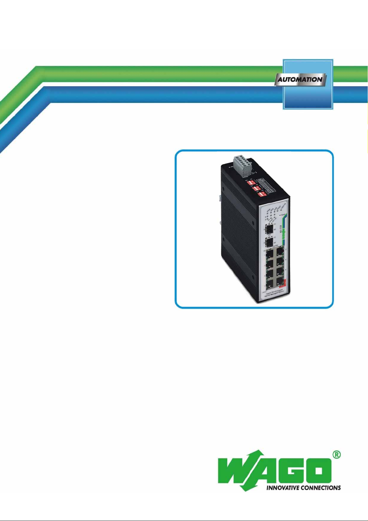
Manual
WAGO ETHERNET Accessories 852
7-Port 100BASE-TX + 2-Slot 100BASE-FX
Industrial Managed Switch
852-104
Assembly, Installation and Handling
Version 1.1.3
Pos: 3 /Alle Serien (Allgemeine Module)/Hinweise zur Doku mentation/Impressum - allgemeine Angaben, Anschr iften, Telefonnummern und E-Mail-Adressen @ 3\mod_12 19151118203_21.doc @ 21060 @ @ 1
Page 2

2 WAGO ETHERNET Accessories 852
852-104 7-Port 100BASE-TX + 2-Slot 100BASE-FX Industrial Managed Switch
© 2011 by WAGO Kontakttechnik GmbH & Co. KG
All rights reserved.
WAGO Kontakttechnik GmbH & Co. KG
Hansastraße 27
D-32423 Minden
Phone: +49 (0) 571/8 87 – 0
Fax: +49 (0) 571/8 87 – 1 69
E-Mail: [email protected]
Web: http://www.wago.com
=== Ende der Liste für Textmarke Einband_vorne ===
Technical Support
Phone: +49 (0) 571/8 87 – 5 55
Fax: +49 (0) 571/8 87 – 85 55
E-Mail: [email protected]
Every conceivable measure has been taken to ensure the accuracy and
completeness of this documentation. However, as errors can never be fully
excluded, we always appreciate any information or suggestions for improving the
documentation.
E-Mail: [email protected]
We wish to point out that the software and hardware terms as well as the
trademarks of companies used and/or mentioned in the present manual are
generally protected by trademark or patent.
Manual
Version 1.1.3
Page 3

WAGO ETHERNET Accessories 852 Table of Contents 3
852-104 7-Port 100BASE-TX + 2-Slot 100BASE-FX Industrial Managed Switch
Pos: 5 /Dokumentation allgemein/Verzeichnisse/ I nhaltsverzeichnis - ohne Gliederung - und Verzeichnis @ 3\ mod_1219151230875_21.doc @ 21063 @ @ 1
Table of Contents
1 Important Notes........................................................................................... 5
1.1 Legal Bases ...............................................................................................5
1.1.1 Subject to Changes............................................................................... 5
1.1.2 Personnel Qualification........................................................................ 5
1.1.3 Proper Use of the Industrial Switches.................................................. 5
1.1.4 Technical Condition of Specified Devices........................................... 5
1.2 Standards and Regulations for Operating the Industrial Switches............ 6
1.3 Symbols..................................................................................................... 7
1.4 Safety
1.5 Font
1.6 Number Notation..................................................................................... 11
2 General........................................................................................................ 12
2.1 Package Contents.................................................................................... 12
2.2
Industrial Ethernet Technology............................................................... 12
2.3 Switching
Information ....................................................................................9
Conventions.................................................................................... 10
Technology ............................................................................12
3 Hardware Description ...............................................................................14
3.1 Connectors............................................................................................... 15
3.1.1 10/100BASE-TX Ports....................................................................... 15
3.1.2 100BASE-FX Ports............................................................................ 15
3.1.3 RS-232 (RJ-45)................................................................................... 15
3.2 Views....................................................................................................... 16
3.2.1 Front View of Industrial Managed Switch......................................... 16
3.2.2 TOP View of Industrial Managed Switch.......................................... 17
3.2.3 Back View of Industrial Managed Switch.......................................... 18
3.3 Display elements..................................................................................... 19
3.3.1 Unit LED´s .........................................................................................19
3.3.2 Port LED´S......................................................................................... 20
3.3.3 Reset Button ....................................................................................... 20
3.4 Operating elements.................................................................................. 21
3.5 Connection
3.5.1
Power Input (PWR/RPS).................................................................... 23
elements............................................................................... 23
4 Assembly..................................................................................................... 24
5 Installation.................................................................................................. 24
5.1 DIN Rail Mounting................................................................................. 24
6 Connect Devices......................................................................................... 26
6.1 DC Power Connection............................................................................. 26
6.2 External Alarm Contact Connection....................................................... 26
6.3 Fiber Cable Connection........................................................................... 27
6.4 Copper Cable Connection ....................................................................... 28
6.5 Console Port Cable Connection.............................................................. 28
7 Enhanced Features.....................................................................................29
7.1 Jet Ring – for Communication Reliability.............................................. 29
7.2 How Jet Ring Recovers in less than 300 ms........................................... 29
Manual
Version 1.1.3
Page 4

4 Table of Contents WAGO ETHERNET Accessories 852
852-104 7-Port 100BASE-TX + 2-Slot 100BASE-FX Industrial Managed Switch
7.3 Xpress Ring............................................................................................. 30
7.4 Coupling Ring......................................................................................... 31
8 Configuration............................................................................................. 32
8.1 Overview of Configuration Options........................................................ 32
8.2 A - Console Port...................................................................................... 33
8.2.1 Connecting a HyperTerminal............................................................. 34
8.3 B – Menu driven User Interface via Telnet............................................. 38
8.3.1 DHCP Configuration Menu................................................................ 42
8.3.2 Device Control Menu (DCM) ............................................................43
8.3.3 (DCM)/Bridge Menu..........................................................................45
8.3.4 Coupling Ring ....................................................................................51
8.3.5 (DCM)/VLAN (Virtual Local Area Networks) Menu .......................52
8.3.5.1 VLAN Type Select Menu.............................................................. 53
8.3.5.2 Tag-based
8.3.6
Management Setup Menu (MSM)...................................................... 67
VLANs......................................................................... 54
8.4 C – Using the Internet Browser Interface ............................................... 74
8.4.1 Overview ............................................................................................ 74
8.4.2 System Details.................................................................................... 75
8.4.3 Configuration...................................................................................... 77
8.4.4 Bridge Menu....................................................................................... 79
8.4.5 Coupling Ring ....................................................................................84
8.4.6 Virtual Local Area Networks (VLAN)............................................... 85
8.4.7 IGMP Menu – Using the IGMP Menu............................................... 93
8.4.8 The MAC Menu ................................................................................. 94
8.4.9 QoS Menu........................................................................................... 97
8.4.10 Management Configurations.............................................................. 99
8.4.11 SNMP Configurations...................................................................... 100
8.5 D – Command Line Interface via Telnet/Console port.........................107
8.5.1 Simple Net Management Protocol (SNMP) configurations using CLI114
=== Ende der Liste für Textmarke Verzeichnis_vorne ===
9 Technical Data..........................................................................................117
9.1 Approvals.............................................................................................. 118
10 Troubleshooting .......................................................................................119
11 Appendix
11.1 Appendix
................................................................................................... 120
A........................................................................................... 120
11.1.1 Console Cable (RJ-45 to DB9)......................................................... 120
11.1.2 RJ-45 Cables..................................................................................... 121
11.2 Appendix B ...........................................................................................122
11.2.1 Application Diagram........................................................................ 122
11.3 Appendix C ...........................................................................................123
11.3.1 SNMP Trap List ...............................................................................123
11.4 Appendix D........................................................................................... 124
11.4.1 Default Settings................................................................................ 124
List of Figu
List of Tables
res.................................................................................................... 128
...................................................................................................... 131
Manual
Version 1.1.3
Page 5

WAGO ETHERNET Accessories 852 Important Notes 5
852-104 7-Port 100BASE-TX + 2-Slot 100BASE-FX Industrial Managed Switch
Pos: 7.1 /Alle Serien (Allgemeine Module)/Überschr iften für alle Serien/Wichtige Erläuterungen - Übersc hrift 1 @ 4\mod_1241428899156_21.doc @ 32170 @ 1 @ 1
1 Important Notes
Pos: 7.2 /Alle Serien (Allgemeine Module)/Wic hti ge E r läuterungen/Einleitung Wichtige Erläuterungen @ 3\ mod _122 1059818031_21.doc @ 21717 @ @ 1
This section includes an overall summary of the most important safety
requirements and notes that are mentioned in each individual section. To protect
your health and prevent damage to devices as well, it is imperative to read and
carefully follow the safety guidelines.
Pos: 7.3 /Alle Serien (Allgemeine Module)/Überschr iften für alle Serien/Rechtliche Grundlagen - Übersc hr ift 2 @ 3\mod_1221060626343_21.doc @ 21726 @ 2 @ 1
1.1 Legal Bases
Pos: 7.4 /Alle Serien (Allgemeine Module)/Wic hti ge E r läuterungen/Änderungsvorbehalt @ 3\mod_1221060036 484_ 21.doc @ 21720 @ 3 @ 1
1.1.1 Subject to Changes
WAGO Kontakttechnik GmbH & Co. KG reserves the right to provide for any
alterations or modifications that serve to increase the efficiency of technical
progress. WAGO Kontakttechnik GmbH & Co. KG owns all rights arising from
the granting of patents or from the legal protection of utility patents. Third-party
products are always mentioned without any reference to patent rights. Thus, the
existence of such rights cannot be excluded.
Pos: 7.5 /Serie 852 (Ethernet-Zubehör)/Wichtige Er läuterungen/Personalqualifikation @ 3\mod_12223 46340968_21.doc @ 22264 @ 3 @ 1
1.1.2 Personnel Qualification
All sequences implemented on Series 852 devices may only be carried out by
electrical specialists with sufficient knowledge in automation. The specialists
must be familiar with the current norms and guidelines for the devices and
automated environments.
All changes to the controller should always be carried out by qualified personnel
with sufficient sufficient skills in PLC programming.
Pos: 7.6 /Serie 852 (Ethernet-Zubehör)/Wichtige Er läuterungen/Bestimmungsgemäße Verwendung @ 3\mod_1222 346110578_21.doc @ 22258 @ 3 @ 1
1.1.3 Proper Use of the Industrial Switches
The device is designed for the IP30 protection class. It is protected against the
insertion of solid items and solid impurities up to 2.5 mm in diameter, but not
against water penetration. Unless otherwise specified, the device must not be
operated in wet and dusty environments.
Pos: 7.7 /Alle Serien (Allgemeine Module)/Wic hti ge E r läuterungen/Technischer Zustand der Geräte @ 3\mod_1221060 446109_21.doc @ 21723 @ 3 @ 1
1.1.4 Technical Condition of Specified Devices
The components to be supplied Ex Works, are equipped with hardware and
software configurations, which meet the individual application requirements.
WAGO Kontakttechnik GmbH & Co. KG will be exempted from any liability in
case of changes in hardware or software as well as to non-compliant usage of
components.
Please send your request for modified and new hardware or software
configurations directly to WAGO Kontakttechnik GmbH & Co. KG.
Pos: 7.8 /Serie 852 (Ethernet-Zubehör)/Wichtige Er läuterungen/Normen und Richtlinien @ 3\mod_12223462394 53_21.doc @ 22261 @ 2 @ 1
Manual
Version 1.1.3
Page 6

6 Important Notes WAGO ETHERNET Accessories 852
852-104 7-Port 100BASE-TX + 2-Slot 100BASE-FX Industrial Managed Switch
1.2 Standards and Regulations for Operating the Industrial Switches
Please observe the standards and regulations that are relevant to installation:
• The data and power lines must be connected and installed in compliance
with the standards to avoid failures on your installation and eliminate any
danger to personnel.
• For installation, startup, maintenance a nd repair, please observe the accident
prevention regulations of your machine (e.g., BGV A 3, "Electrical
Installations and Equipment").
• Emergency stop functions and equipment must not be deactivated or
otherwise made ineffective. See relevant standards (e.g., DIN EN 418).
• Your installation must be equipped in accordance to the EMC guidelines so
electromagnetic interferences can be eliminated.
Pos: 7.9 /Dokumentation allgemein/Gliederungse lemente/---Seitenwechsel--- @ 3\mod_1221108045078_0.doc @ 21810 @ @ 1
• Please observe the safety measures against electrostatic discharge according
to DIN EN 61340-5-1/-3. When handling the modules, ensure that
environmental factors (persons, workplace and packing) are well grounded.
• The relevant valid and applicable standards and guidelines regarding the
installation of switch cabinets must be observed.
Manual
Version 1.1.3
Page 7
WAGO ETHERNET Accessories 852 Important Notes 7
852-104 7-Port 100BASE-TX + 2-Slot 100BASE-FX Industrial Managed Switch
Pos: 7.10 /Alle Serien (Allgemeine Module)/Hinweise zur Dokumentation/Symbole @ 3\mod_1217394197593_21. doc @ 21010 @ 2 @ 1
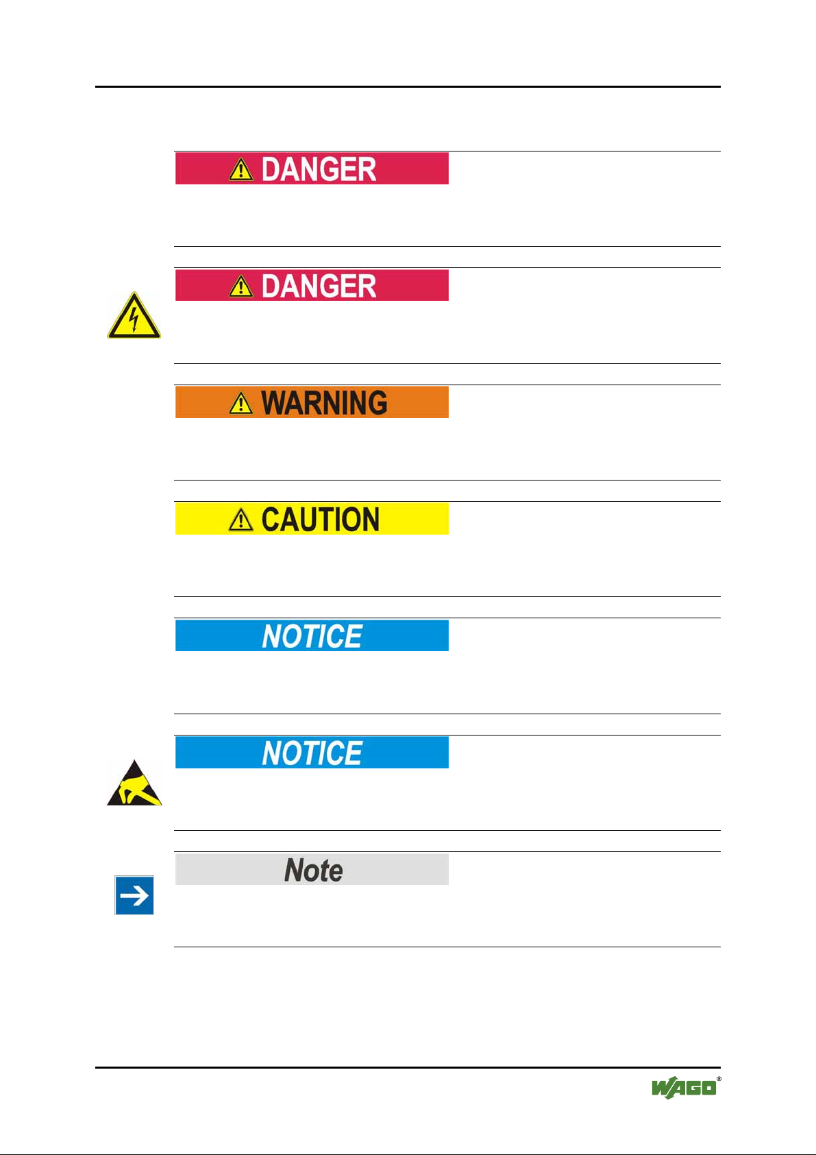
1.3 Symbols
Personal Injury!
Indicates a high-risk, imminently hazardous situation which, if not avoided, will
result in death or serious injury.
Personal Injury Caused by Electric Current!
Indicates a high-risk, imminently hazardous situation which, if not avoided, will
result in death or serious injury.
Personal Injury!
Indicates a moderate-risk, potentially hazardous situation which, if not avoided,
could result in death or serious injury.
Personal Injury!
Indicates a low-risk, potentially hazardous situation which, if not avoided, may
result in minor or moderate injury.
Damage to Property!
Indicates a potentially hazardous situation which, if not avoided, may result in
damage to property.
Damage to Property Caused by Electrostatic Discharge (ESD)!
Indicates a potentially hazardous situation which, if not avoided, may result in
damage to property.
Important Note!
Indicates a potential malfunction which, if not avoided, however, will not result in
damage to property.
Manual
Version 1.1.3
Page 8
8 Important Notes WAGO ETHERNET Accessories 852
852-104 7-Port 100BASE-TX + 2-Slot 100BASE-FX Industrial Managed Switch
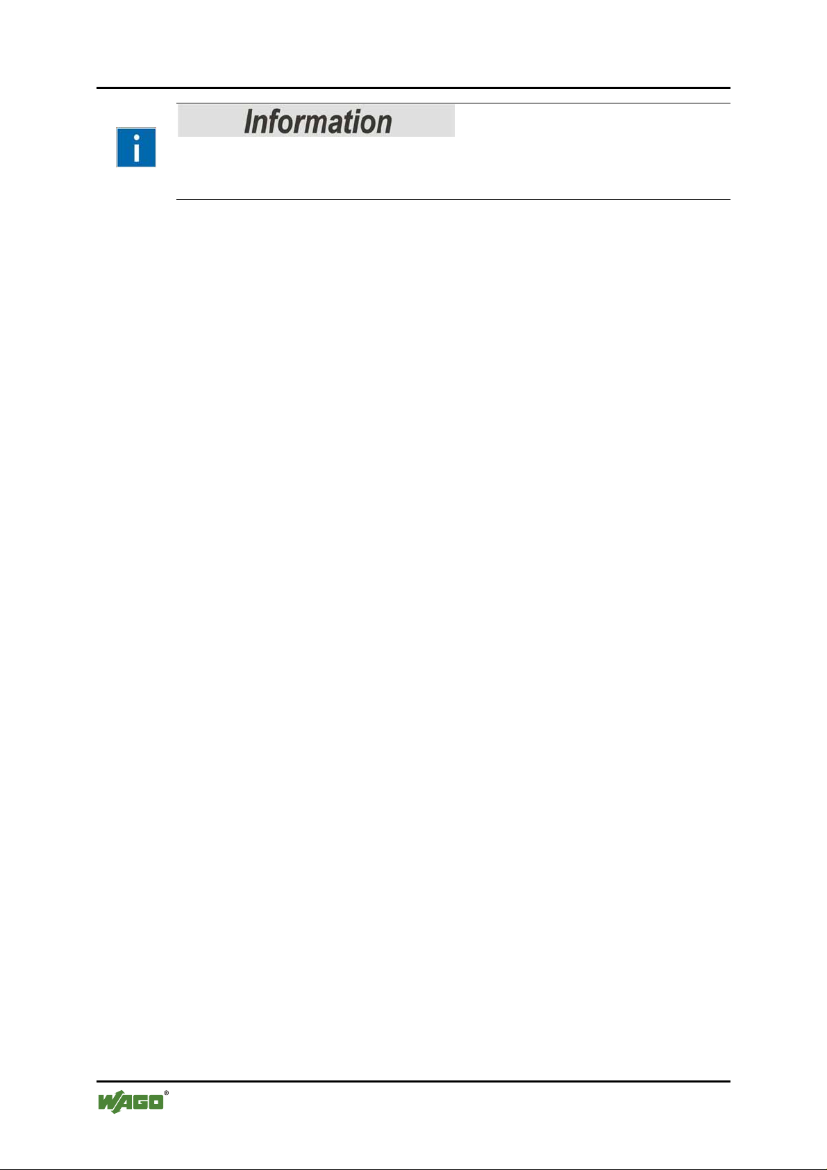
Additional Information:
Refers to additional information which is not an integral part of this
documentation (e.g., the Internet).
Pos: 7.11 /Dokumentation allgemein/Gliederungse lemente/---Seitenwechsel--- @ 3\mod_1221108045078_0.doc @ 21810 @ @ 1
Manual
Version 1.1.3
Page 9
WAGO ETHERNET Accessories 852 Important Notes 9
852-104 7-Port 100BASE-TX + 2-Slot 100BASE-FX Industrial Managed Switch
Pos: 7.12 /Serie 852 (Ethernet-Zubehör)/Wic hti ge Erläuterungen/Sicherheitshinweise 852-103, 104 @ 3\ mod_1227801823937_21.doc @ 25317 @ 2 @ 1
1.4 Safety Information
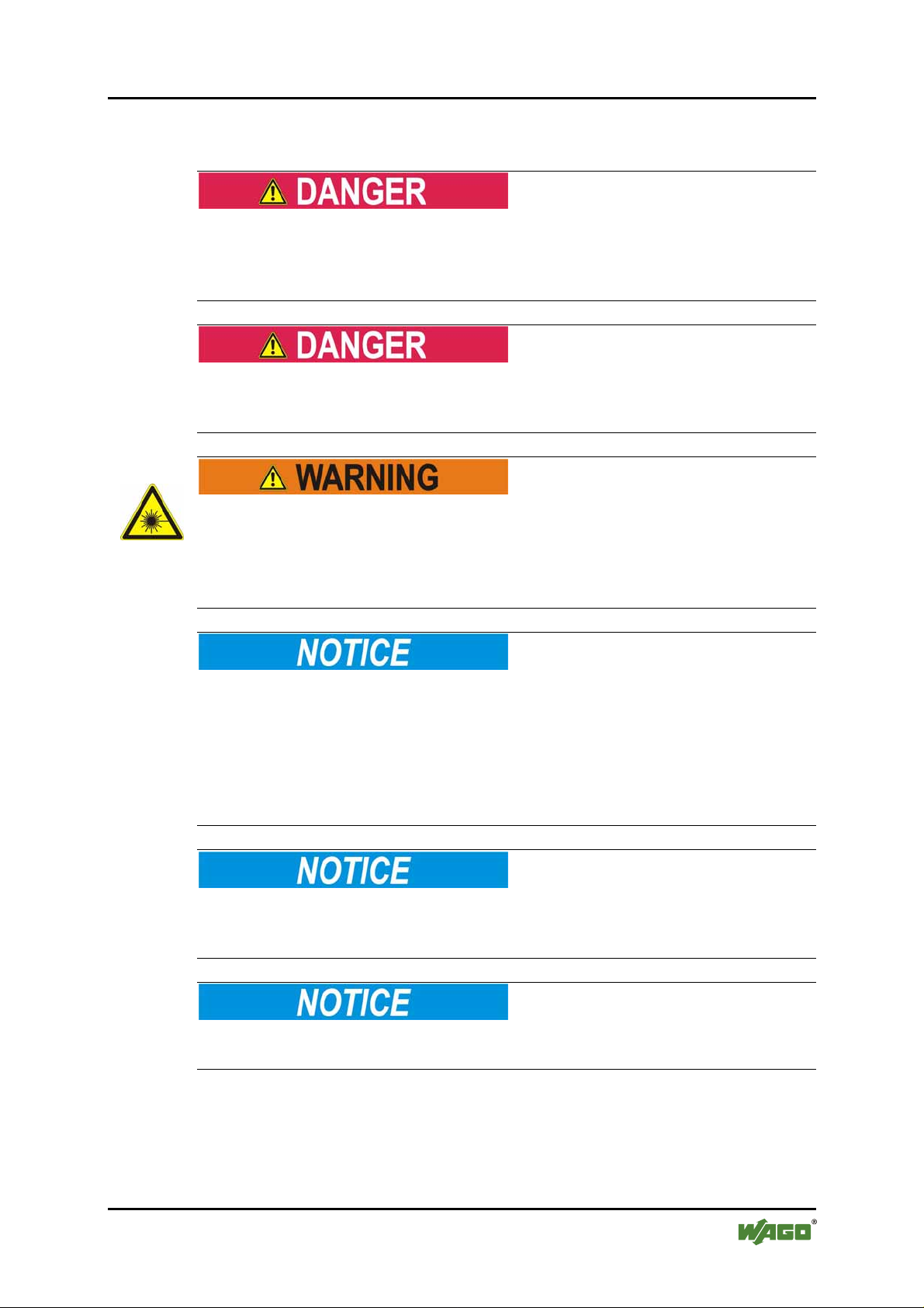
Warning of physical injury
Industrial Switches are exposed operating equipment. They may only be
assembled in housings, cabinets or in electrical operation rooms. Access is only
permitted via a key or tool to authorized qualified personnel.
Warning of physical injury
All power sources to the device must always be switched off before performing
any installation, repair or maintenance work.
Warning of physical Injury due to electric current
Because invisible laser radiation may be emitted from the aperture of the port
when no cable is connected, avoid exposure to laser radiation and do not stare into
open apertures.
It concerns here a laser class 1 according EN 60825-1.
Warning of damage to equipment
The components are not resistant against materials having seeping and insulating
properties such as: aerosols, silicones, triglycerides (found in some hand creams).
If it cannot be determined that these materials appear in the component
environment, then the components must be installed in an enclosure that is
resistant against the above mentioned materials. Clean tools and materials are
generally required to operate the device/module.
Warning of damage to equipment
Soiled contacts must be cleaned using oil-free compressed air or with ethyl
alcohol and leather cloths.
Warning of damage to equipment
Do not use contact sprays, which could possibly impair contact area functionality.
Manual
Version 1.1.3
Page 10
10 Important Notes WAGO ETHERNET Accessories 852
852-104 7-Port 100BASE-TX + 2-Slot 100BASE-FX Industrial Managed Switch
Warning of damage to equipment
Avoid reverse polarity of data and power lines as this may damage the devices.
Warning of damage to equipment
This is a Class A product. In a domestic environment this product may cause
radio interference in which case the user may be required to take adequate
measures.
Warning of damage to equipment by electrostatic discharge
The devices are equipped with electronic components that may be destroyed by
electrostatic discharge when touched.
Pos: 7.13 /Alle Serien (Allgemeine Module)/Hinweise zur Dokumentation/Schriftkonventionen @ 3\mod_12210 59521437_21.doc @ 21714 @ 2 @ 1
1.5 Font Conventions
Table 1: Font Conventions
Font type Indicates
Names of paths and data files are marked in italic-type.
e.g.: C:\Programme\WAGO-I/O-CHECK
Menu items are marked in bold letters.
e.g.: Save
A greater-than sign between two names means the selection of a
menu item from a menu.
e.g.: File > New
Designation of input or optional fields are marked in bold letters,
e.g.: Start of measurement range
e.g.: Enter the value “4 mA” under Start of measurement range.
Pushbuttons in dialog boxes are marked with bold letters in square
brackets.
e.g.: [Input]
Keys are marked with bold letters in square brackets.
e.g.: [F5]
Pos: 7.14 /Dokumentation allgemein/Gliederungse lemente/---Seitenwechsel--- @ 3\mod_1221108045078_0.doc @ 21810 @ @ 1
italic
Menu
>
Input
“Value” Input or selective values are marked in inverted commas.
[Button]
[Key]
Manual
Version 1.1.3
Page 11

WAGO ETHERNET Accessories 852 Important Notes 11
852-104 7-Port 100BASE-TX + 2-Slot 100BASE-FX Industrial Managed Switch
Pos: 7.15 /Alle Serien (Allgemeine Module)/Hinweise zur Dokumentation/Zahlensysteme @ 3\mod_1221059454 015_ 21.doc @ 21711 @ 2 @ 1
1.6 Number Notation
Table 2: Number Notation
Number code Example Note
Decimal 100 Normal notation
Hexadecimal 0x64 C notation
Pos: 8 /Dokumentation allgemein/Gliederungsele mente/---Seitenwechsel--- @ 3\mod_1221108045078_0.doc @ 21810 @ @ 1
Binary '100'
'0110.0100'
In quotation marks, nibble separated with
dots (.)
Manual
Version 1.1.3
Page 12

12 General WAGO ETHERNET Accessories 852
852-104 7-Port 100BASE-TX + 2-Slot 100BASE-FX Industrial Managed Switch
Pos: 9.1 /Serie 852 (Ethernet-Zubehör)/Einleitu ng/ Einleitung @ 3\mod_1222676076609_21.doc @ 22308 @ 1 @ 1
2 General
Pos: 9.2 /Serie 852 (Ethernet-Zubehör)/Einleitu ng/ Paketinhalt 852-104 @ 3\mod_1227538895750_21.doc @ 25239 @ 2 @ 1
2.1 Package Contents
• One Industrial Switch
• One console port cable (RJ-45 to DB9)
• DIN rail bracket
• Protective caps for unused ports
Pos: 9.3 /Serie 852 (Ethernet-Zubehör)/Einleitu ng/ Industrielle Ethernet Technologie @ 3\mod_1222680431 062_21.doc @ 22311 @ 2 @ 1
2.2 Industrial Ethernet Technology
The line of switches from WAGO ensure the scalability of your network
infrastructure with outstanding electrical and mechanical characteristics. These
robust devices are designed for industrial use and they are fully compliant with
IEEE802.3, 802.3u.
They have function monitoring and redundant voltage supply with a supply
voltage range of 9 … 48 V. Alarm functions are enabled via DIP switch.
Characteristics such as auto negotiation and auto MDI/MDIX (crossover) on all
10/100 BaseTX ports are also realized, as is a store-and-forward switching mode.
Pos: 9.4 /Serie 852 (Ethernet-Zubehör)/Einleitu ng/ Switch Technologie @ 3\mod_1222683606296_21.doc @ 22317 @ 2 @ 1
2.3 Switching Technology
Another approach to pushing beyond the limits of Ethernet technology is the
development of switching technology. A switch bridge Ethernet packets at the
MAC address level of the Ethernet protocol transmitting among connected
Ethernet or Fast Ethernet LAN segments.
Switching is a cost-effective way of increasing the total network capacity
available to users on a local area network. A switch increases capacity and
decreases network loading by dividing a local area network into different
segments, which don’t compete with each other for network transmission
capacity.
Pos: 9.5 /Dokumentation allgemein/Gliederungse lemente/---Seitenwechsel--- @ 3\mod_1221108045078_0.doc @ 21810 @ @ 1
Manual
Version 1.1.3
Page 13

WAGO ETHERNET Accessories 852 General 13
852-104 7-Port 100BASE-TX + 2-Slot 100BASE-FX Industrial Managed Switch
Pos: 9.6 /Serie 852 (Ethernet-Zubehör)/Gerätebeschr eibung/Eigenschaften allgemein @ 3\mod_1220960 1042 03_21.doc @ 21260 @ @ 1
The Industrial Switch was designed for easy installation in an industrial
environment where vibration, shock, heat, and RF interference may be
commonplace.
The Industrial Switch, with its small, compact size, was specifically designed for
easy DIN rail mounting and can be installed where space is limited.
The Industrial Switch is ideal for deployment with multiple high-speed servers for
shared bandwidth 10 Mbps or 100 Mbps workgroups. With the highest bandwidth
200 Mbps (100 Mbps full duplex mode), any port can provide workstations with a
congestion-free data pipe for simultaneous access to the server.
The Industrial Switch is expandable by cascading two or more switches together
in a ‘daisy-chain’ fashion. As all ports support 200 Mbps, the Industrial Switch
can be cascaded from any port and to any number of switches.
The Industrial Switch combines dynamic memory allocation with store-and
forward switching to ensure that the buffer is effectively allocated for each port,
while controlling the data flow between the transmit and receive nodes to
guarantee against all possible packet loss.
Pos: 9.7 /Serie 852 (Ethernet-Zubehör)/Gerätebeschr eibung/Eigenschaften 852-104 @ 3\mod_12209633697 34_21.doc @ 21263 @ @ 1
Other key features are:
Pos: 10 /Dokumentation allgemein/Gliederungsele mente/---Seitenwechsel--- @ 3\mod_1221108045078_0.doc @ 21810 @ @ 1
• Seven (7) 10/100Base-TX, two (2) 100Base-FX (SFP type fiber
transceivers) and One (1) Console port (RJ-45)
• Rugged metal-IP30 Case
• Vibration/Shock operational
• DIP switches to enable or disable alarm functions
• Under and over-power detection function
• Wide voltage range: 9 … 48 V
• SNMP management (HP Open View and IBM/Tivoli NetView capable)
• Http/Web browser user interface, CLI and Menu driven user interfaces via
both console and telnet
• Xpress Ring (redundant ring) with less than 50 ms recovery time
• Auto negotiation NWay on RJ-45 port
• Remote & local management
• Extends fiber distance to 2 km (6600 feet) for multi-mode and up to 30 km
(99000 feet) for long-haul single-mode fiber
• Status LEDs for quick and easy network activity monitoring
• Firmware upgradeable
• Console Port (RJ-45) - Use this port for local device management.
Configure the device through a Terminal Emulator/TELNET Program
• RJ-45 Ethernet port supports auto MDI/MDI-X. Fiber Port- Connect various
fiber optic cables (multi mode, single mode, long haul single mode, WDM)
to the fiber port.
Manual
Version 1.1.3
Page 14

14 Hardware Description WAGO ETHERNET Accessories 852
852-104 7-Port 100BASE-TX + 2-Slot 100BASE-FX Industrial Managed Switch
Pos: 11.1 /Serie 852 (Ethernet-Zubehör)/Gerätebesc hreibung/Hardwarebeschreibung 852-104 @ 3\mod_1222 689911062_21.doc @ 22323 @ 1 @ 1
3 Hardware Description
The Industrial Managed Switch was developed with both “Xpress Ring” and “Jet
Ring” features. The Jet ring offers recovery time of less than 300 ms in case of
any network-link failure – and the Xpress Ring can recover from such a failure
within 50 ms. This makes the Industrial Managed Switch particularly suited for
industrial applications that demand the utmost reliability. The device comes with
7 copper and 2 fiber ports that provide 10/100 Base fiber-to-copper conversion.
With its industrial design, the Industrial Managed Switch ensures "always-on"
connectivity, eliminating costly network downtime.
Being SNMP-ready, the Industrial Managed Switch enables network managers to
remotely monitor the entire network’s status quickly and easily via an RJ-45 or a
console port connection. This Industrial Managed Switch can extend an
enterprise’s industrial Ethernet configuration range up to 30 km, while
simultaneously minimizing troubleshooting time. The Industrial Managed Switch
is designed with 'plug-n-play' features for hassle-free integration into today's
managed mixed-cabling network configurations.
Pos: 11.2 /Dokumentation allgemein/Gliederungse lemente/---Seitenwechsel--- @ 3\mod_1221108045078_0.doc @ 21810 @ @ 1
Featuring Auto MDI/MDI-X detection for direct connection to a workstation,
switch or hub, network managers no longer need to worry about the cable
configuration (cross-over or straight through) when establishing connections
between RJ-45 ports.
The Industrial Managed Switch has auto-negotiation capabilities that allow it to
support connection with leading NWay switches. In full-duplex mode, this unit
can sustain distances of up to 2 km (for multi-mode fiber) and 30 km (for longhaul single-mode fiber) between it and a LAN switch or another switch or
data/file server.
The Industrial Managed Switch features both RJ-45 jacks and slots for LC (SFPtype) fiber-optic connectors that allow it to connect a 10/100Base-TX network to
a 100Base-FX (fiber-based) network.
Manual
Version 1.1.3
Page 15

WAGO ETHERNET Accessories 852 Hardware Description 15
852-104 7-Port 100BASE-TX + 2-Slot 100BASE-FX Industrial Managed Switch
Pos: 11.3 /Serie 852 (Ethernet-Zubehör)/Gerätebesc hreibung/Anschlüsse 852-104 @ 3\mod_122268969471 8_21. doc @ 22320 @ 2333 @ 1
3.1 Connectors
This Industrial Managed Switch utilizes ports with fiber or copper port connectors
functioning under Ethernet and/or Fast Ethernet protocols.
3.1.1 10/100BASE-TX Ports
The 10/100BASE-TX ports support network speeds of either 10 Mbps or
100 Mbps, and can operate in half- and full-duplex transfer modes. The ports also
offer automatic MDI/MDI-X crossover detection that gives true “plug and play”
capability – just plug the network cables into the ports and the ports will adjust
according to the end-node devices. The following are the recommended cables for
the RJ-45 connectors:
• 10M – Cat 3 or better / 100M – Cat 5 or better
3.1.2 100BASE-FX Ports
The 100BASE-FX ports add fiber-based Fast Ethernet links to your network
device. Complying with IEEE 802.3u, these ports can transmit data at 100 Mbps
in full-duplex mode across distances of up to 2 km over multi-mode and up to
30 km over single-mode fiber-optic cable. The fiber ports have LC-type
connectors.
3.1.3 RS-232 (RJ-45)
When connecting your Switch's console port to your COM port, use the provided
console cable. For further information see in chapter “RJ-45 Cables “.
Pos: 11.4 /Dokumentation allgemein/Gliederungse lemente/---Seitenwechsel--- @ 3\mod_1221108045078_0.doc @ 21810 @ @ 1
Manual
Version 1.1.3
Page 16
16 Hardware Description WAGO ETHERNET Accessories 852
852-104 7-Port 100BASE-TX + 2-Slot 100BASE-FX Industrial Managed Switch
Pos: 11.5 /Serie 852 (Ethernet-Zubehör)/Gerätebesc hreibung/Ansichten 852-104 @ 3\mod_1221733301796_21. doc @ 21897 @ 2333 @ 1
3.2 Views
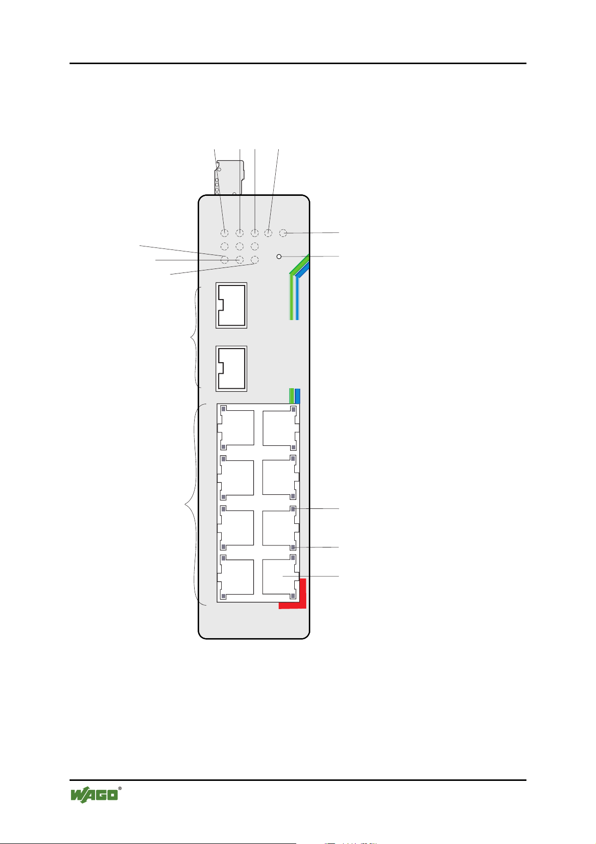
3.2.1 Front View of Industrial Managed Switch
4321
LASERON
ALM
RPS
T
O
F
F
TX
RX
LIN
E
POST
852-104
Reset
5
6
14
13
12
PWR
8
9
100
K/AC
LN
8
11
100
9
100
1
3
10
5
7
LNK/ACT
7-port 10/100+2-port
100-FX Managed Switch
Figure 1: Front view of switch
TX
RX
10/100
CONSOLE
2
4
6
(RS-232)
7
8
9
Manual
Version 1.1.3
Page 17
WAGO ETHERNET Accessories 852 Hardware Description 17
852-104 7-Port 100BASE-TX + 2-Slot 100BASE-FX Industrial Managed Switch
Pos. Description Pos. Description
1 Primary Power LED 2 Redundant Power LED
3 Alarm LED 4 POST LED
5 LASER ON LED for fiber
6 Reset button
optic modules
7 TX port 100Mbps LED 8 TX port LNK/ACT LED
9 RS-232 Console port (RJ-45) 10 TX port 10/100 Mbps (7)
11 100 Base-FX LC Fiberslots
12 Fiber 100 Mbps LED (2)
(SFP-type) (2)
13 Fiber port LNK/ACT LED (2) 14 Fiber port Offline LED (2)
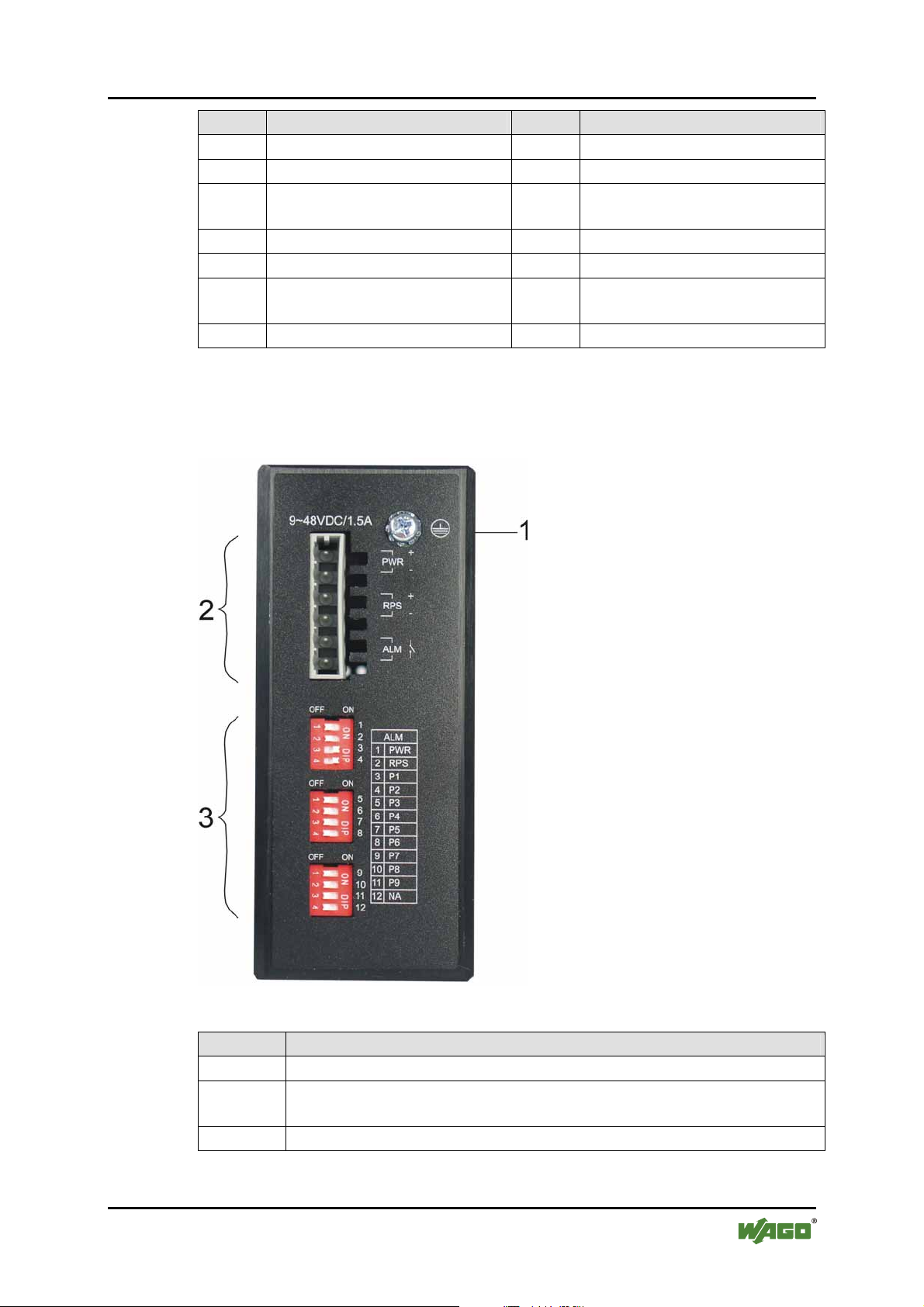
3.2.2 TOP View of Industrial Managed Switch
Figure 2: Top view of switch
Position Description
1 Grounding Screw
2 Terminal block (male connector) for power input (PWR/RPS) and
alarm dry contact
3 DIP Switches
Manual
Version 1.1.3
Page 18
18 Hardware Description WAGO ETHERNET Accessories 852
852-104 7-Port 100BASE-TX + 2-Slot 100BASE-FX Industrial Managed Switch
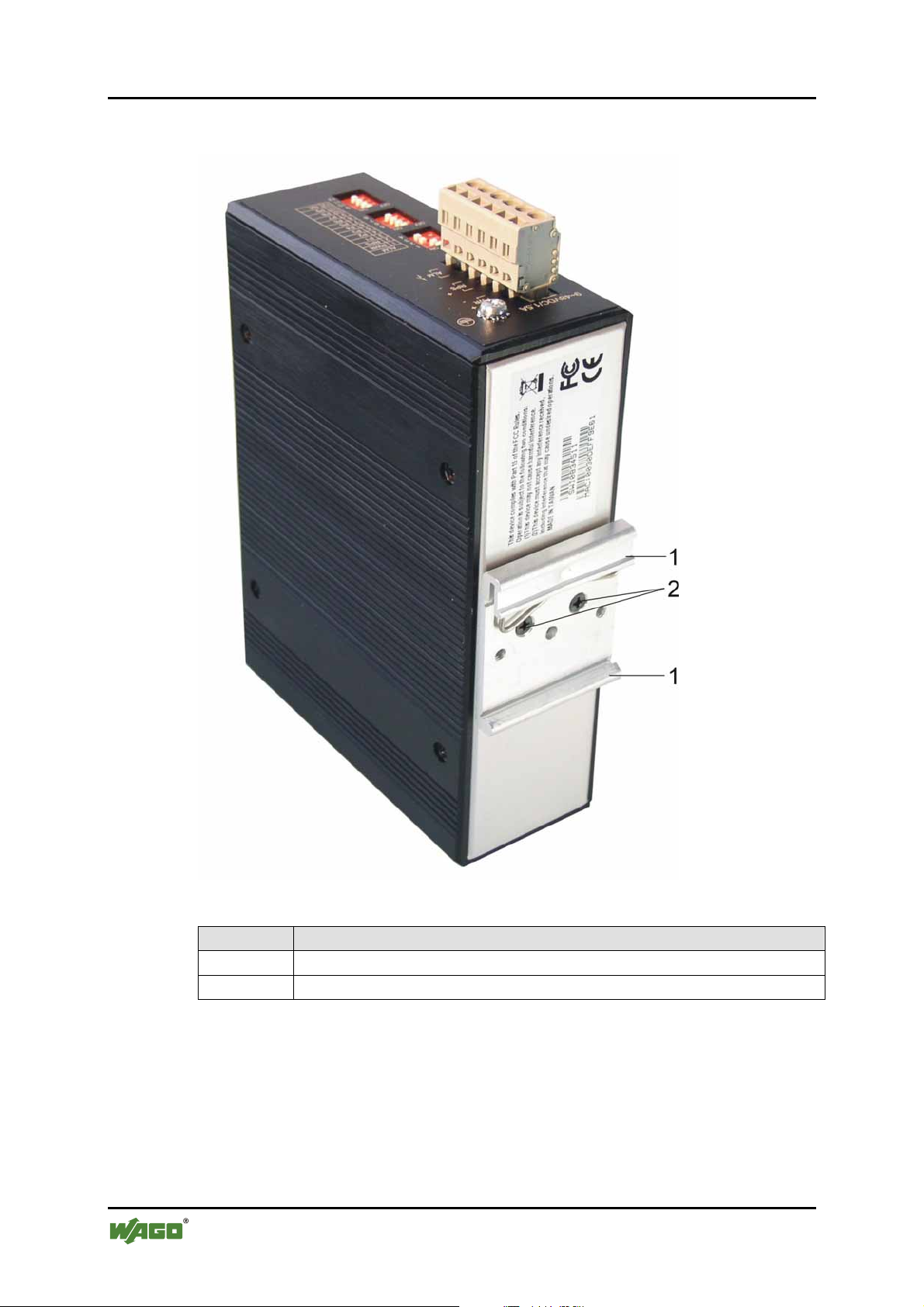
3.2.3 Back View of Industrial Managed Switch
Figure 3: Back view of switch
Position Description
1 DIN Rail Bracket
2 Screw
Pos: 11.6 /Dokumentation allgemein/Gliederungse lemente/---Seitenwechsel--- @ 3\mod_1221108045078_0.doc @ 21810 @ @ 1
Manual
Version 1.1.3
Page 19
WAGO ETHERNET Accessories 852 Hardware Description 19
852-104 7-Port 100BASE-TX + 2-Slot 100BASE-FX Industrial Managed Switch
Pos: 11.7 /Serie 852 (Ethernet-Zubehör)/Gerätebesc hreibung/LED-Anzeigen 852-104 @ 3\mod_12217388791 87_21.doc @ 21908 @ 2333 @ 1
3.3 Display elements
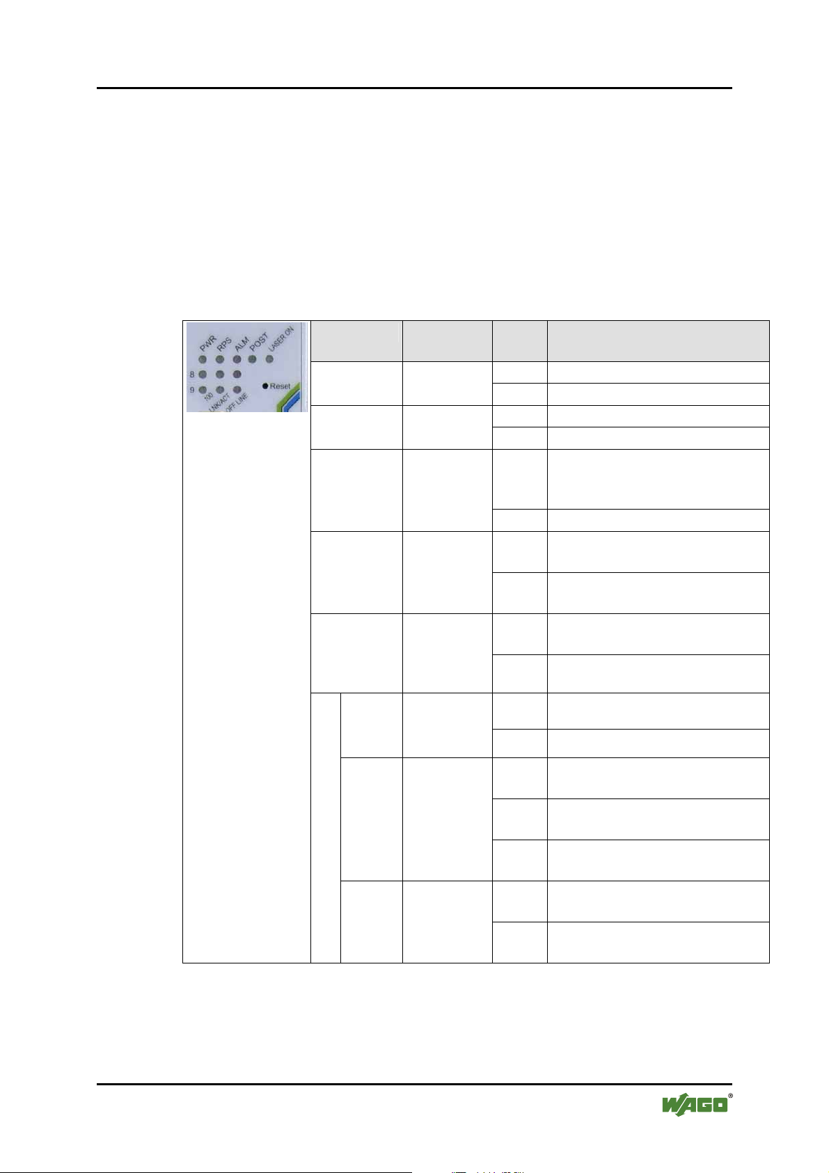
This Industrial Managed Switch is equipped with Unit LEDs to enable you to
quickly determine the status of the Switch, as well as Port LEDs to see what is
happening across your connection.
They are as follows:
3.3.1 Unit LED´s
Table 3: Unit LED´s
Figure 4: Unit LED´s
LED Desig-
nation
Power LED
Power LED
ALM Alarm LED
POST POST LED
LASER ON LASER ON
LED for
fiber-optic
modules
8
/
9
LINK/
ACT
100 Mbps
LED
Fiber port
LNK/ACT
LED
OFF
LINE
Fiber port
Offline
LED
Status Description
Green Switch uses primary power PWR Primary
Off Primary power off or failure
Green Switch uses redundant power RPS Redundant
Off Redundant power off failure
Red Illuminated when power fails
or link fails or ring fails (for
Arbiter node)
Off No alarm to report
Green POST function successfully
performed
Flashi
ng
Indicating POST function upon
start-up
Yellow Illuminated when fiber port is
in use
Off No fiber port is in use
Green Port operating at 100 Mps 100 Fiber
Off Port operating at 10 Mps
Green Illuminated when connectors
are attached
Flashi
ng
Data traffic passing through
fiber port
Off No valid link established on
fiber port
Red Illuminated Red when SFP
device does not exist
Off Both SFP devices are properly
plug in
Manual
Version 1.1.3
Page 20
20 Hardware Description WAGO ETHERNET Accessories 852
852-104 7-Port 100BASE-TX + 2-Slot 100BASE-FX Industrial Managed Switch
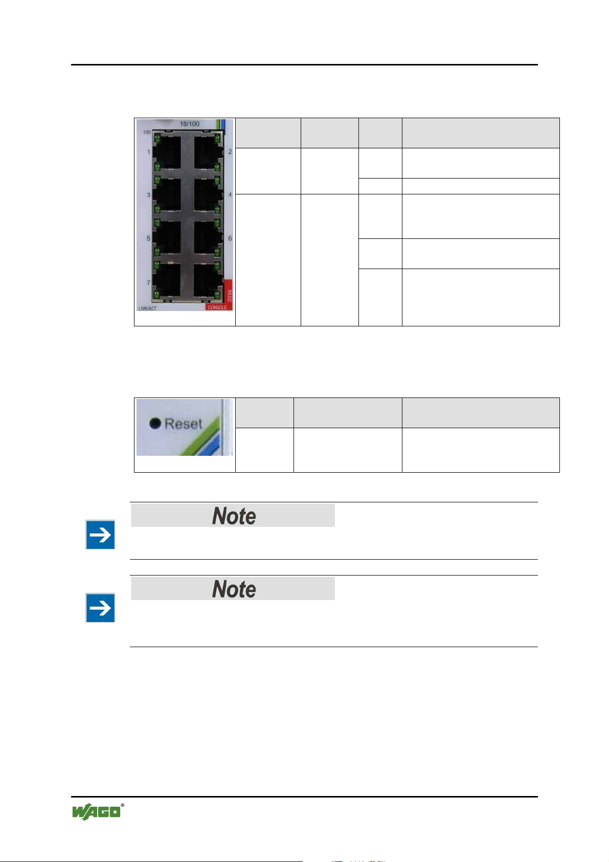
3.3.2 Port LED´S
Table 4: Port LED´s
LED Desig-
nation
100 TX-port
100 Mbps
LED
LNK/ACT TX port
LNK/
ACT
LED
Figure 5: Port LED´s
Status Description
Green Port operating at 100 Mps (1
LED for each port)
Off Port operating at 10 Mps
Green Illuminated when connectors
are attached (1 LED for each
port)
Flashing
Data traffic passing through
port
Off No valid link established on
port
3.3.3 Reset Button
Table 5: Reset Button
Figure 6: Reset Button
Please note
The fiber module does not support “half-duplex” mode.
Please note
Use a pointed object like straightened paper clip or toothpick to press the Reset
button.
Desig-
Status Description
nation
Reset Press the button for
2 seconds and
release
Restart the system
Pos: 11.8 /Dokumentation allgemein/Gliederungse lemente/---Seitenwechsel--- @ 3\mod_1221108045078_0.doc @ 21810 @ @ 1
Manual
Version 1.1.3
Page 21
WAGO ETHERNET Accessories 852 Hardware Description 21
852-104 7-Port 100BASE-TX + 2-Slot 100BASE-FX Industrial Managed Switch
Pos: 11.9 /Serie 852 (Ethernet-Zubehör)/Gerätebesc hreibung/Bedienelemente 852-104 @ 3\mod_12217422828 75_21.doc @ 21918 @ 2 @ 1
3.4 Operating elements
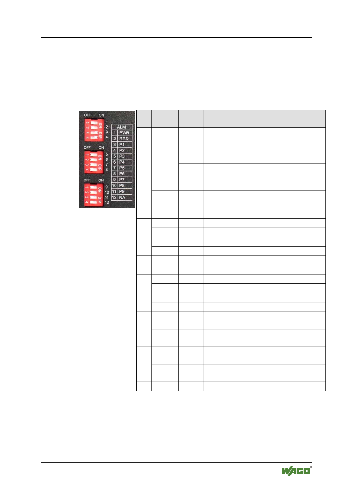
On the top side of the Industrial Managed Switch there are DIP switches to
configure the alarm and arbiter configurations.
The meaning of the DIP switch settings are described below:
Table 6: Operating elements
Figure 7: Operating
elements
No. Desig-
nation
2 RPS
P1 ON Port 1 link alarm reporting is enabled 3
OFF ort 1 link alarm reporting is enabled
P2 ON Port 2 link alarm reporting is enabled 4
OFF Port 2 link alarm reporting is disabled
P3 ON Port 3 link alarm reporting is enabled 5
OFF Port 3 link alarm reporting is disabled
P4 ON Port 4 link alarm reporting is enabled 6
OFF Port 4 link alarm reporting is disabled
P5 ON Port 5 link alarm reporting is enabled 7
OFF Port 5 link alarm reporting is disabled
P6 ON Port 6 link alarm reporting is enabled 8
OFF Port 6 link alarm reporting is disabled
P7 ON Port 7 link alarm reporting is enabled 9
OFF Port 7 link alarm reporting is disabled
P8 ON Port 8 (SFP) link alarm reporting is
10
OFF Port 8 (SFP) link alarm reporting is
P9 ON Port 9 (SFP) link alarm reporting is
11
OFF Port 9 (SFP) link alarm reporting is
12 NA Not assigned
State Function
ON Master power alarm reporting is enabled 1 PWR
OFF Master power alarm reporting is disabled
ON Redundant power alarm reporting is
enabled
OFF Redundant power alarm reporting is
disabled
enabled
disabled
enabled
disabled
DIP-switches let the user manually turn “ON/OFF” any port, the external Alarm,
or the redundant power supply.
DIP-switch to the “ON” position to manually enable the alarm function for the
port. Default is “OFF”.
Manual
Version 1.1.3
Page 22

22 Hardware Description WAGO ETHERNET Accessories 852
852-104 7-Port 100BASE-TX + 2-Slot 100BASE-FX Industrial Managed Switch
The following is the Recommended Procedure for configuring and setting DIPswitches during initial installation:
1 Turn all DIP-switches “OFF”.
2 Install the Industrial Switch into your network.
3 Decide which port(s) need to be monitored or should trigger the alarm.
4 Turn the corresponding port DIP-switch “ON”.
5 Activate the Industrial Switch.
Pos: 11.10 /Dokumentation allgemein/Gliederungs el emente/---Seitenwechsel--- @ 3\mod_1221108045078_0.doc @ 21810 @ @ 1
Manual
Version 1.1.3
Page 23
WAGO ETHERNET Accessories 852 Hardware Description 23
852-104 7-Port 100BASE-TX + 2-Slot 100BASE-FX Industrial Managed Switch
Pos: 11.11 /Serie 852 (Ethernet-Zubehör)/Gerätebesc hreibung/Anschlusselemente @ 3\mod_122769847 9625 _21.doc @ 25299 @ 2 @ 1
3.5 Connection elements
Pos: 11.12 /Serie 852 (Ethernet-Zubehör)/Gerätebesc hreibung/Spannungsversorgung @ 3\mod_12217458 7442 1_21.doc @ 21930 @ 3 @ 1
3.5.1 Power Input (PWR/RPS)
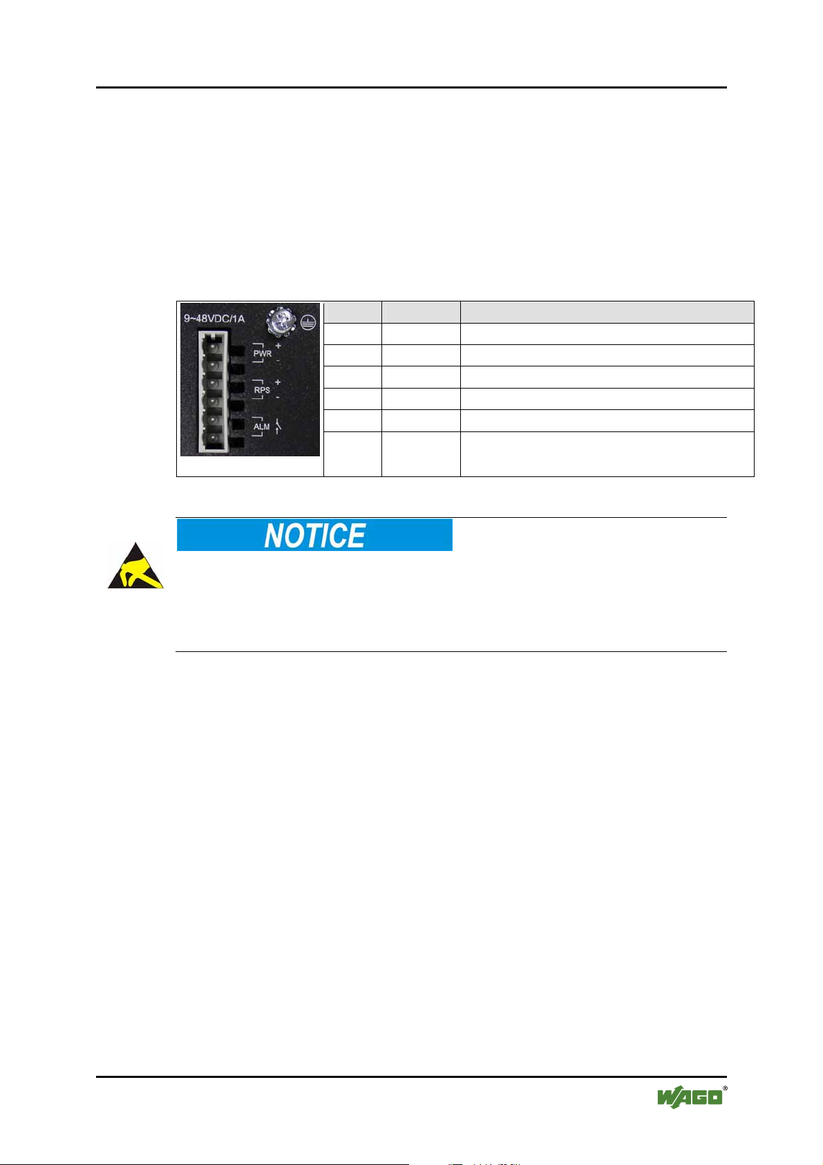
The female connector can easily be connected to the 6-pole male connector
located on the top of the switch.
The male connector shows the following pin assignment:
Table 7: Power Input (PWR/RPS)
Name Designation
+ PWR Primary DC input
- PWR Primary DC input
+ RPS Redundant DC input
- RPS Redundant DC input
ALM Contact for external alarm
ALM Contact for external alarm
Figure 8: Power Input
Pos: 12 /Dokumentation allgemein/Gliederungsele mente/---Seitenwechsel--- @ 3\mod_1221108045078_0.doc @ 21810 @ @ 1
Warning of damage to equipment by electrostatic discharge
DC Powered Switch: Power is supplied through an external DC power source.
Check the technical specification section for information about the DC power
input voltage. Since the switch does not include a power switch, plugging its
power adapter into a power outlet will immediately power it on.
Manual
Version 1.1.3
Page 24
24 Assembly WAGO ETHERNET Accessories 852
852-104 7-Port 100BASE-TX + 2-Slot 100BASE-FX Industrial Managed Switch
Pos: 13.1 /Alle Serien (Allgemeine Module)/Überschr iften für alle Serien/Montieren - Überschrift 1 @ 3\ mod_1225446744750_21.doc @ 24900 @ 1 @ 1
4 Assembly
Pos: 13.2 /Serie 852 (Ethernet-Zubehör)/Montieren/ Montageort 852-103 @ 4\mod_1236927232906_21.doc @ 28359 @ 1 @ 1
5 Installation
The location selected to install the Industrial Switch may greatly affect its
performance. When selecting a site, we recommend considering the following
rules:
• Install the Industrial Switch at an appropriate place. See in chapter
“Technical Data” for the acceptable temperature and humidity operating
ranges.
• Fix the provided brackets at the back of the Industrial Switch to a DIN rail
to protect the switch from falling.
Warning of physical Injury due to electric current
Because invisible laser radiation may be emitted from the aperture of the port
when no cable is connected, avoid exposure to laser radiation and do not stare into
open apertures.
Pos: 13.3 /Serie 852 (Ethernet-Zubehör)/Montieren/ Montageort 852-104 @ 3\mod_1221817555515_21.doc @ 21972 @ @ 1
Please note
Default Communication Parameter:
IP Address: Default: 192.168.0.254
Subnet Mask: Default: 255.255.255.0
RS-232 Parameter:
- Bits per seconds: 38400
- Data Bits: 8
- Parity: None
- Stop Bits: 1
- Flow control: None
Pos: 13.4 /Serie 852 (Ethernet-Zubehör)/Montieren/ Montieren auf Tragschiene @ 3\mod_1222422141203_21. doc @ 22278 @ 2 @ 1
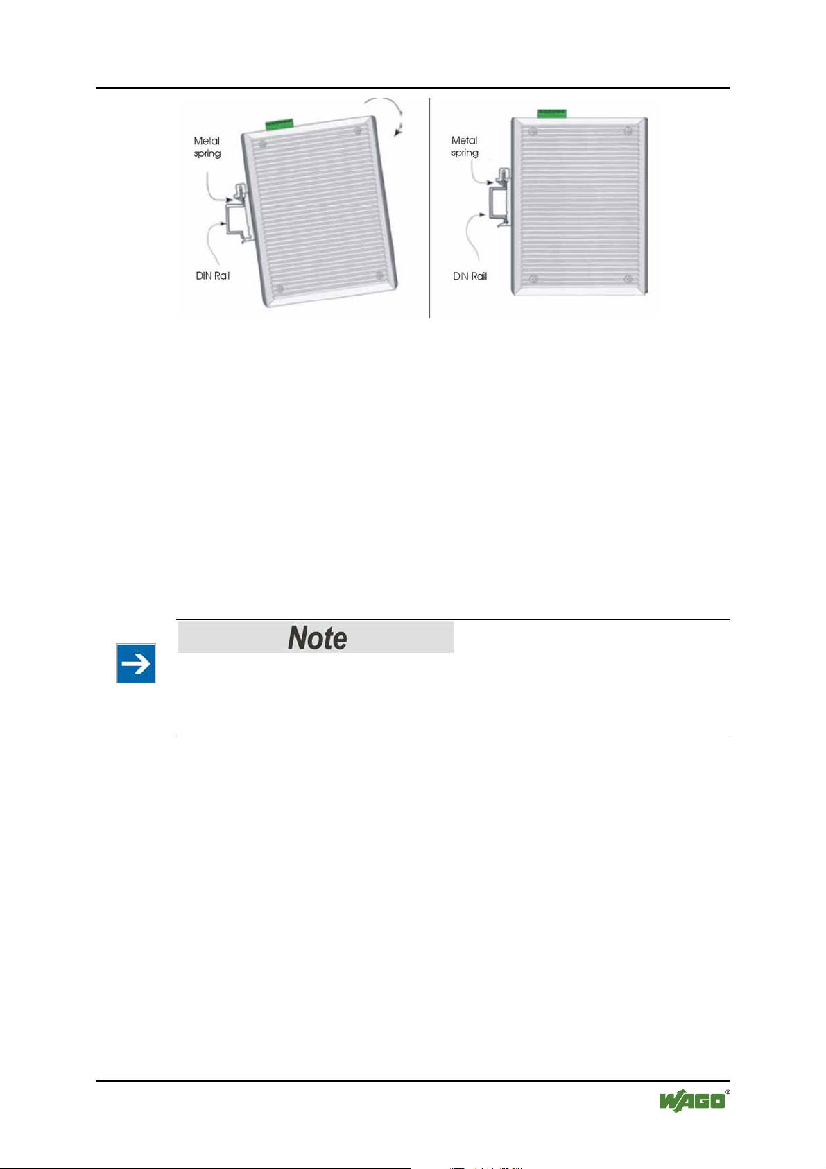
5.1 DIN Rail Mounting
The aluminum DIN Rail attachment plate should already be affixed to the back
panel of the Industrial Switch. If you need to attach the DIN Rail plate, assure that
the stiff metal spring is situated towards the top. Attaching the Industrial Switch to
the DIN rail is easy, just align, and attach the top rail, then press down and snap
forward the Industrial Switch to snap in the bottom rail, as shown in the figures
below.
Manual
Version 1.1.3
Page 25
WAGO ETHERNET Accessories 852 Installation 25
852-104 7-Port 100BASE-TX + 2-Slot 100BASE-FX Industrial Managed Switch
Figure 9: DIN Rail Mounting
The setup of the Industrial Switch can be performed using the following steps:
• The surface must support at least 1.5 kg for the Industrial Switch.
• Visually inspect th e DC power jack and make sure that it is fully secured to
the power adapter.
Pos: 14 /Dokumentation allgemein/Gliederungsele mente/---Seitenwechsel--- @ 3\mod_1221108045078_0.doc @ 21810 @ @ 1
• Make sure that there is proper heat dissipation from and adequate ventilation
around the Industrial Switch. Do not place heavy objects on the Industrial
Switch.
• The carrier rail must optimally support the EMC measures integrated into
the system and the shielding of the internal data bus connections.
Important note
Grounding Industrial Switch will help eliminate the effects of noise due to
electromagnetic interference (EMI). Always run the ground connection from the
ground screw to the grounding surface prior to connecting DC power.
Manual
Version 1.1.3
Page 26

26 Connect Devices WAGO ETHERNET Accessories 852
852-104 7-Port 100BASE-TX + 2-Slot 100BASE-FX Industrial Managed Switch
Pos: 15 /Alle Serien (Allgemeine Module)/Überschr i ften für alle Serien/Geräte anschließen - Überschrif t 1 @ 3\mod_1234172889468_21.doc @ 27460 @ 1 @ 1
6 Connect Devices
Pos: 16 /Serie 852 (Ethernet-Zubehör)/Montieren/Ansc hluss Spannungsversorgung @ 3\mod_1222084220921_ 21.doc @ 21997 @ 2 @ 1
6.1 DC Power Connection
The Industrial Switch uses a DC power supply of 9 … 48 V DC.
The primary and redundant power connection is provided via a terminal block
located at the top of the Industrial Switch.
The terminal block is composed of six contact pins and can be inserted and
removed easily by hand to connect to the six pin terminal block receptor (male
contacts located on the body of the Switch).
The Switch’s power supply automatically self adjusts to the local power source
and may be powered on without having any or all LAN segment cables connected.
1 Check the front panel LEDs as the device is powered on to verify that the
Power LED is lit. If not, check that the power cable is correctly and securely
plugged in.
2 If a redundant power supply is connected, an RPS LED will be illuminated.
3 „PWR +/-„ conductors:
To connect or disconnect the conductors, actuate the spring directly in the
female connector using a screwdriver or an operating tool and insert or
remove the conductor.
4 For the back up DC connection, follow the same procedure as above. Attach
power wires to the terminal block (in the position marked RPS +/-).
5 If the terminal block is not already inserted into the block receptor of the
Switch, do so now.
Pos: 17 /Serie 852 (Ethernet-Zubehör)/Montieren/Ansc hluss Alarm @ 3\mod_1222175755015_21.doc @ 22048 @ 2 @ 1
6.2 External Alarm Contact Connection
The Industrial Switch has one alarm contact connection point located on the grey
terminal block on the top panel. For detailed instructions on how to connect the
alarm contact power wires to the two ALM contacts of the 6 contact terminal
block connector, see the procedure for connecting DC Power in the section above
(it is the same procedure).
You can connect the alarm circuit to any warning device which the user´s factory
or industry already has installed in the control room or factory floor. When a fault
occurs, the Industrial Switch will send a signal through the alarm contact, to
activate this external alarm. The alarm contact has two terminals that form a fault
circuit for connecting to alarm system.
An alarm will be signaled in the following situations:
1 Port link failure (e.g.: cable disconnected, device breakdown, etc.)
Manual
Version 1.1.3
Page 27
WAGO ETHERNET Accessories 852 Connect Devices 27
852-104 7-Port 100BASE-TX + 2-Slot 100BASE-FX Industrial Managed Switch
2 PWR/RPS:
a Power failure a Power cord is disconnected, power supply malfunction,
etc.
b Input power is out of the range listed in the specifications (9 …48 V)
Pos: 18 /Serie 852 (Ethernet-Zubehör)/Montieren/Ansc hluss Glasfaserkabel @ 3\mod_1222249492312_21.d oc @ 22158 @ 2 @ 1
6.3 Fiber Cable Connection
When connecting fiber cable to a 100BASE-FX port on the Industrial Managed
Switch, be sure the correct type (LC) of connector and SFP module is used.
Various types of multi mode, single mode, or WDM SFP modules are sold
separately. Follow the steps below to properly connect the fiber cabling:
Please note
Remove and keep the fiber port’s (LC) rubber covers. When not connected to a
fiber cable, the rubber cover should be in place to protect the fiber optics.
Pos: 19 /Dokumentation allgemein/Gliederungsele mente/---Seitenwechsel--- @ 3\mod_1221108045078_0.doc @ 21810 @ @ 1
1 Plug in the appropriate SFP modules.
2 Check that the fiber terminators are clean. You can clean the cable plugs by
wiping gently with a clean tissue or cotton ball moistened with a little
ethanol. Dirty fiber terminators on fiber cables will impair the quality of the
light transmitted through the cable and lead to degraded performance on the
port.
3 Connect one end of the cable to the LC port on the Industrial Managed
Switch and the other end to the fiber port of the other device.
Please note
When inserting the cable, be sure the tab on the plug clicks into position to ensure
that it is properly connected.
4 Check the corresponding port LED on the Industrial Managed Switch to be
sure that the connection is valid. (Refer to the LED chart)
Manual
Version 1.1.3
Page 28

28 Connect Devices WAGO ETHERNET Accessories 852
852-104 7-Port 100BASE-TX + 2-Slot 100BASE-FX Industrial Managed Switch
Pos: 20 /Serie 852 (Ethernet-Zubehör)/Montieren/Ansc hluss Kupferkabel @ 3\mod_1222251156843_21.doc @ 22161 @ 2 @ 1
6.4 Copper Cable Connection
The Industrial Managed Switch’s 10/100BASE-TX RJ-45 Ethernet ports fully
support auto sensing and auto negotiation.
1 Insert one end of a Category 3/4/5/5e type twisted pair cable into an
available RJ-45 port on the Industrial Managed Switch and the other end
into the port of the selected network node.
2 Check the corresponding port LED on the Industrial Managed Switch to be
sure that the connection is valid. (Refer to LED chart)
Pos: 21 /Serie 852 (Ethernet-Zubehör)/Montieren/Ansc hluss Konsolenanschlusskabel @ 3\mod_1222251 4994 21_21.doc @ 22164 @ 2 @ 1
6.5 Console Port Cable Connection
The console port (RJ-45) provides the local management facility.
1 Insert the RJ-45 side of the (8 pin RJ-45 to DB9) cable into the RJ-45
console port on the Industrial Managed Switch and the other end into the
COM port of the computer.
Pos: 22 /Dokumentation allgemein/Gliederungsele mente/---Seitenwechsel--- @ 3\mod_1221108045078_0.doc @ 21810 @ @ 1
2 Configure the Hyper Terminal settings as mentioned in chapter “Connecting
a HyperTerminal “.
For console port (8 pin RJ-45) pin assignment, please see in the chapter “Console
Cable (RJ-45 to DB9) “.
Manual
Version 1.1.3
Page 29

WAGO ETHERNET Accessories 852 Enhanced Features 29
852-104 7-Port 100BASE-TX + 2-Slot 100BASE-FX Industrial Managed Switch
Pos: 23.1 /Serie 852 (Ethernet-Zubehör)/Erweiter te Funktionen/Erweiterungen @ 3\mod_1222693989093_ 21. doc @ 22350 @ 1 @ 1
7 Enhanced Features
Pos: 23.2 /Serie 852 (Ethernet-Zubehör)/Erweiter te Funktionen/Jet Ring @ 3\mod_1222694060328_21.doc @ 22356 @ 22 @ 1
7.1 Jet Ring – for Communication Reliability
Setting up Jet Ring (redundant linking) on your network helps to protect critical
links against failure and network loops; and it reduces network downtime to less
than 300 ms.
The Jet Ring function allows users to set up a redundant path in the network to
provide a backup data-transmission route in the event that a connection is abruptly
disconnected or damaged. This is an extremely important feature in industrial
applications because a link failure in a link with no backup can cause several
minutes of network downtime and thus cause heavy losses.
7.2 How Jet Ring Recovers in less than 300 ms
The Jet Ring protocol is designed to optimize redundant communication linking
and deliver a very fast link-recovery period. The Jet Ring automatically identifies
one switch as the “master” of the network, and then automatically blocks ports to
prevent packets from traveling through any of the network’s redundant loop
segments. If one segment of this ring becomes disconnected from the rest of the
network because of a link failure, the Jet Ring protocol automatically re-adjusts
the ring so that the part of the network that was disconnected, re-establishes
contact with the rest of the network.
The user does not need to designate the master switch to use Jet Ring, this is done
automatically.
The Jet Ring ensures smooth operation of industrial automation devices in many
critical applications. It will put your automation system back to full operability in
less than 300 ms if any node of your network goes down.
Manual
Version 1.1.3
Page 30
30 Enhanced Features WAGO ETHERNET Accessories 852
852-104 7-Port 100BASE-TX + 2-Slot 100BASE-FX Industrial Managed Switch
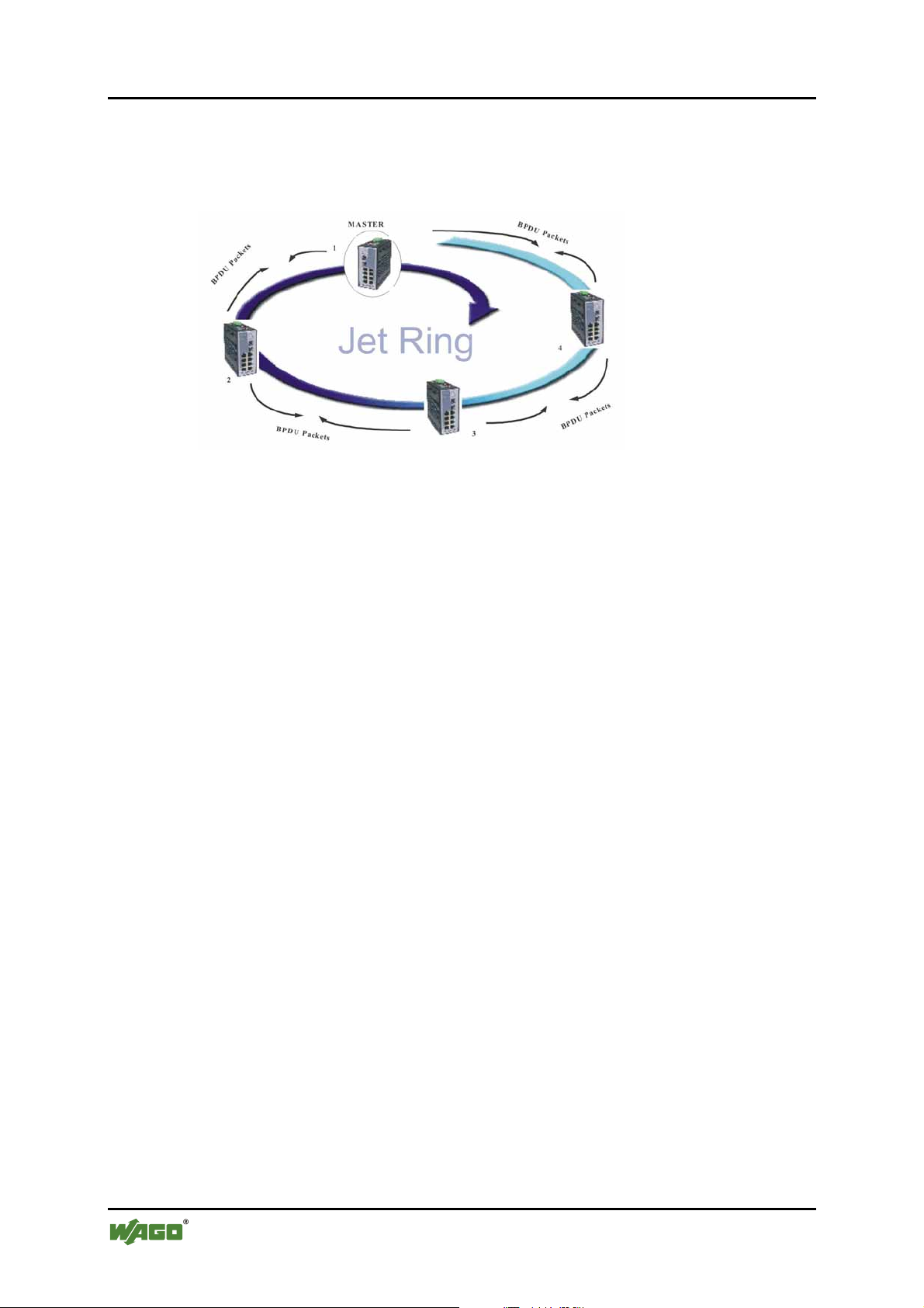
Step 1
You can apply the ring in the diagram below by connecting 4 units of Industrial
Managed Switches.
Figure 10: JetRing
Step 2
Jet Ring then automatically selects the Arbiter switch and the network is ready.
Pos: 23.3 /Serie 852 (Ethernet-Zubehör)/Erweiter te Funktionen/Xpress Ring @ 3\mod_1222694244562_21.doc @ 22359 @ 2 @ 1
7.3 Xpress Ring
Xpress Ring is a ring protocol that enables networks to recover from link failure
within 50 ms. Unlike Jet Ring, it needs some network configuration efforts: The
user must assign two ring ports for each Switch in the ring. The user must also
assign the Arbiter Switch, which will decide if it is necessary to activate the
backup path. For Xpress Ring, any switch can be the arbiter – just remember that
the arbiter switch must be part of the ring.
Apart from rerouting the transmission within 50 ms, the Arbiter Switch will also
issue an alarm when a link failure occurs. The user will then be informed of the
failure and will be able to fix the problem and reconfigure if required.
Xpress Ring is the faster ring recovery technology and is ideal for networks where
the ring topology is not changed very often.
Please refer to the following chapter for the configuration of the Xpress Ring.
Pos: 23.4 /Dokumentation allgemein/Gliederungse lemente/---Seitenwechsel--- @ 3\mod_1221108045078_0.doc @ 21810 @ @ 1
Manual
Version 1.1.3
Page 31
WAGO ETHERNET Accessories 852 Enhanced Features 31
852-104 7-Port 100BASE-TX + 2-Slot 100BASE-FX Industrial Managed Switch
Pos: 23.5 /Serie 852 (Ethernet-Zubehör)/Erweiter te Funktionen/Coupling Ring @ 3\mod_1222693879031_21.doc @ 22347 @ 2 @ 1
7.4 Coupling Ring
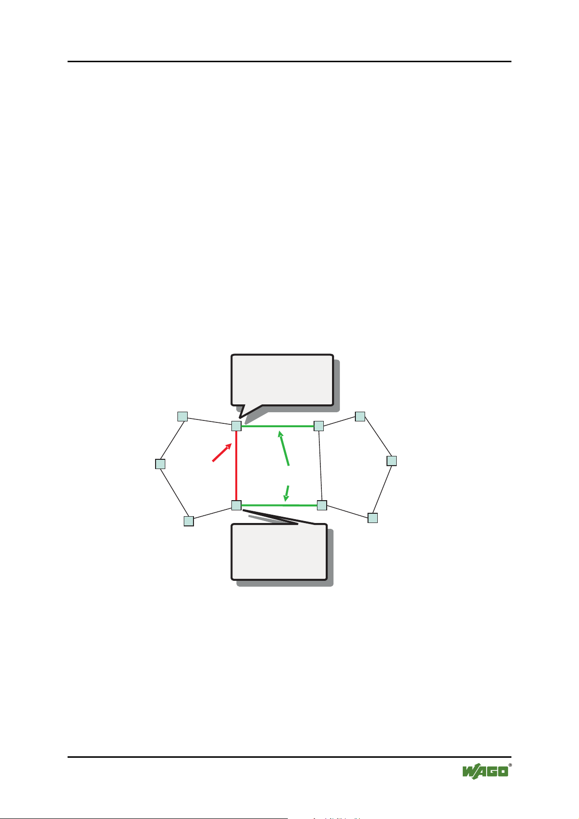
The Coupling Ring function connects two Xpress Rings via redundant links
(Primary Link & Secondary Link). Please refer to the following illustration. When
the primary link (port 2 at the Master Switch of coupling role) fails, the secondary
link (port 2 at the Arbiter Switch of coupling role) will automatically kick in
within milliseconds. The Secondary Link is blocked during normal operations,
and it is enabled automatically when the Primary Link is disconnected. The
Secondary Link is blocked again automatically when the Primary Link recovers.
Control Line of Coupling Ring (port 1 at the Master Switch of coupling role/port
1 at the Arbiter Switch of coupling role) is used for negotiation between Master
and Arbiter Switches of coupling role and to decide when the secondary link
should be enabled or blocked. It is needed to set coupling roles as “Master”,
“Arbiter”, or “Normal” (all other Switches not Master neither Arbiter) to Switches
in the Xpress Ring, and assign coupling’s ring and control ports to the Master and
Arbiter Switches, to one side only of two interconnected rings.
Coupling Ring is designed based on Xpress Ring. For configuring the Coupling
Ring feature, please consult the appropriate chapter in this manual.
Pos: 24 /Dokumentation allgemein/Gliederungsele mente/---Seitenwechsel--- @ 3\mod_1221108045078_0.doc @ 21810 @ @ 1
EXAMPLE:
Forward (Xpress role)
Port 3
Port 1
Arbiter (Xpress role)
Coupling Ring
CONTROL Line
(Ring A)
Forward (Xpress role)
Port 1
Port 3
Figure 11: Coupling Ring
Forward (Xpress role)
Master (Coupling role)
Xpress Ring Ports : 1, 3
Coupling Control Port : 1
Coupling Ring Port : 2
Port 2
Coupling Ring
Port 2
Forward (Xpress role)
Arbiter (Coupling role)
Xpress Ring Ports : 1, 3
Coupling Control Port : 1
Coupling Ring Port : 2
Port 2
RING Lines
Forward (Xpress role)
Port 1
Port 3
Arbiter (Xpress role)
(Ring B)
Forward (Xpress role)
Manual
Version 1.1.3
Page 32

32 Configuration WAGO ETHERNET Accessories 852
852-104 7-Port 100BASE-TX + 2-Slot 100BASE-FX Industrial Managed Switch
Pos: 25.1 /Alle Serien (Allgemeine Module)/Überschr iften für alle Serien/Konfigurieren - Überschri ft 1 @ 5\mod_1247578046546_21.doc @ 37410 @ 1 @ 1
8 Configuration
Pos: 25.2 /Serie 852 (Ethernet-Zubehör)/Konfigur ation/Überblick @ 3\mod_1222694835531_21.doc @ 22365 @ 2 @ 1
8.1 Overview of Configuration Options
For advanced management capabilities, the onboard management agent provides
CLI and menu driven interface configuration programs. These programs can be
accessed by a direct or modem connection to the console port on the front panel
(local), or by a Telnet connection over the network.
The management agent is based on SNMP (Simple Network Management
Protocol). This SNMP agent permits the switch to be managed from any PC in the
network by using management software.
The management agent also includes an embedded HTTP Web agent. This Web
agent can be accessed using a standard Web browser from any computer attached
to the network.
The Industrial Managed Switch gives you the flexibility to access and manage it
by using any or all of the methods described. The administration console and web
browser interfaces are embedded in the switch software and can be used
immediately after setup.
Pos: 25.3 /Dokumentation allgemein/Gliederungse lemente/---Seitenwechsel--- @ 3\mod_1221108045078_0.doc @ 21810 @ @ 1
External SNMP-based network management application
Advantages:
• Communicates with switch functions at the MIB level
• Based on open standards
The three methods for configuring the Industrial Managed Switch management
agent are explained in this chapter.
The first method – Command Line Interface (CLI) via the Console Port to initially
set IP parameters – is explained in part A.
The second is Menu Driven configurations via Telnet – explained in part B.
Part C explains the use of an Internet Browser Interface to configure the Industrial
Managed Switch.
Part D provides some basic operational examples for using CLI via Telnet.
Complete part A and then proceed to either part B, C or D.
Manual
Version 1.1.3
Page 33
WAGO ETHERNET Accessories 852 Configuration 33
852-104 7-Port 100BASE-TX + 2-Slot 100BASE-FX Industrial Managed Switch
Pos: 25.4 /Serie 852 (Ethernet-Zubehör)/Konfigur ation/Anschluss Bediengerät @ 3\mod_1222695068093 _21. doc @ 22372 @ 2 @ 1
8.2 A - Console Port
Local Connection
Prior to accessing the Industrial Managed Switch’s onboard agent via a network
connection, you must first configure it with a valid IP address, subnet mask, and
default gateway using a local connection or the BOOTP protocol.
After configuring the Industrial Managed Switch’s IP parameters, you can access
the onboard configuration program from anywhere within the attached network or
via Internet. The onboard configuration program can be accessed using Telnet
from any computer attached to the network. It can also be managed from any
computer using a Web browser (Internet Explorer 4.0 or above, or Netscape
Navigator 4.0 or above).
Access the Industrial Managed Switch via a terminal emulator (such as Hyper
Terminal) attached to the console port. The console port is set at the factory with
the following default COM port properties. Configure your own terminal to match
the following:
Pos: 25.5 /Dokumentation allgemein/Gliederungse lemente/---Seitenwechsel--- @ 3\mod_1221108045078_0.doc @ 21810 @ @ 1
Table 8: Console Port Terminal
Console Port Terminal
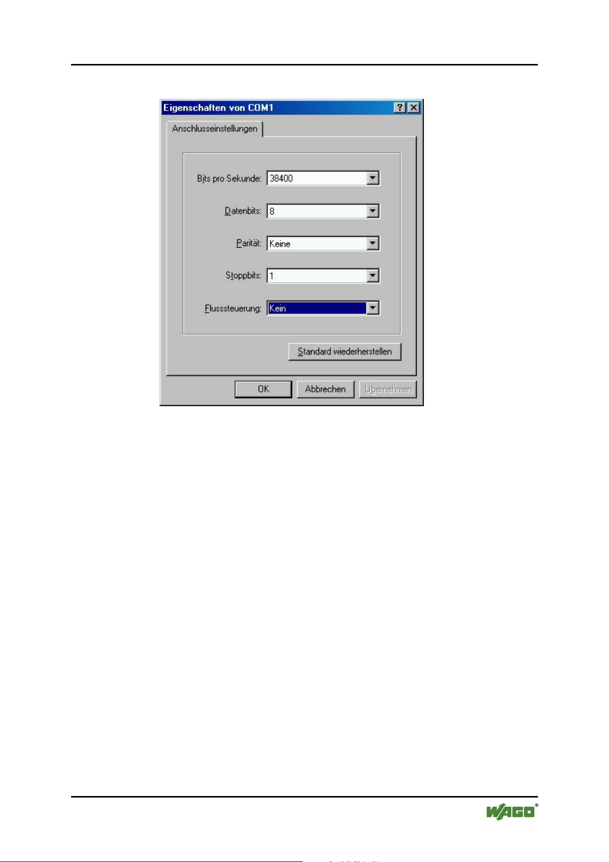
Baud rate 38,400
Data size 8 bits
Parity None
Stop bits 1
Flow Control None
Please note
Ensure that the terminal or PC you are using to make this connection is
configured to match the above settings. Otherwise the connection will not work.
A console port cable is provided with the Industrial Managed Switch to connect
the PC’s COM port with the Industrial Managed Switch’s serial console (RJ-45)
port. Please see in chapter “RJ-45 Cables “ in assignment details.
Manual
Version 1.1.3
Page 34
34 Configuration WAGO ETHERNET Accessories 852
852-104 7-Port 100BASE-TX + 2-Slot 100BASE-FX Industrial Managed Switch
Pos: 25.6 /Serie 852 (Ethernet-Zubehör)/Konfigur ation/Anschluss Hyper Terminal @ 3\mod_1222767696843 _21.doc @ 22434 @ 3 @ 1
8.2.1 Connecting a HyperTerminal
Prior to following the instructions listed below for HyperTerminal, verify that a
console cable (RJ-45 to DB9) connection between the Industrial Managed Switch
and workstation exists. Then follow the steps below:
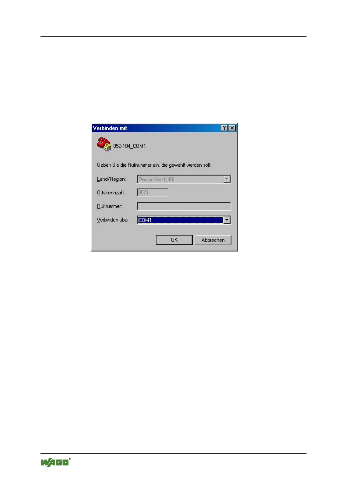
1 Launch the terminal emulation program on the remote workstation and
power on the Industrial Managed Switch. Be sure to select the correct COM
port.
Figure 12: Connect to switch
Manual
Version 1.1.3
Page 35
WAGO ETHERNET Accessories 852 Configuration 35
852-104 7-Port 100BASE-TX + 2-Slot 100BASE-FX Industrial Managed Switch
2 Enter the correct parameters according to the defaults given above.
Figure 13: COM1 properties
Manual
Version 1.1.3
Page 36
36 Configuration WAGO ETHERNET Accessories 852
852-104 7-Port 100BASE-TX + 2-Slot 100BASE-FX Industrial Managed Switch
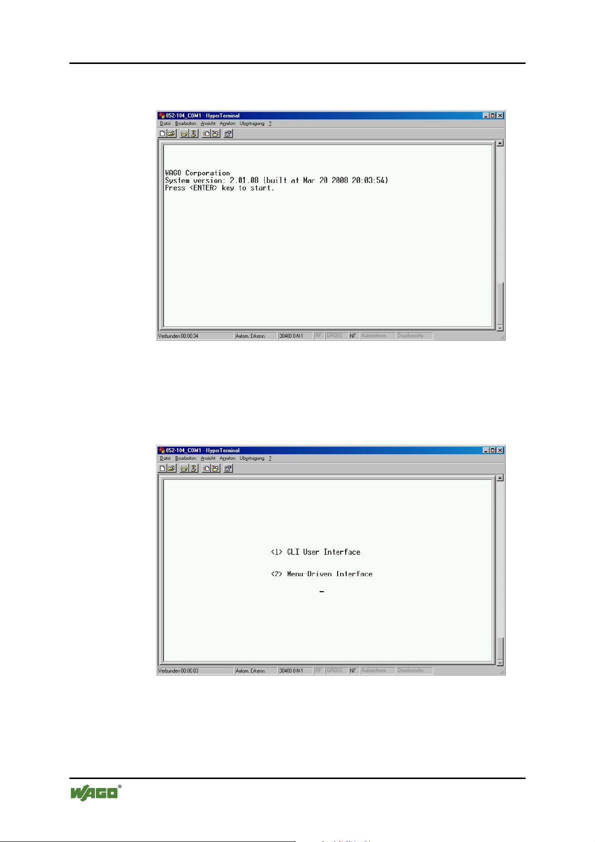
3 The following screen will appear after selecting [OK]. Press [ENTER] to
start and move to the Log in screen.
Figure 14: Systemversion
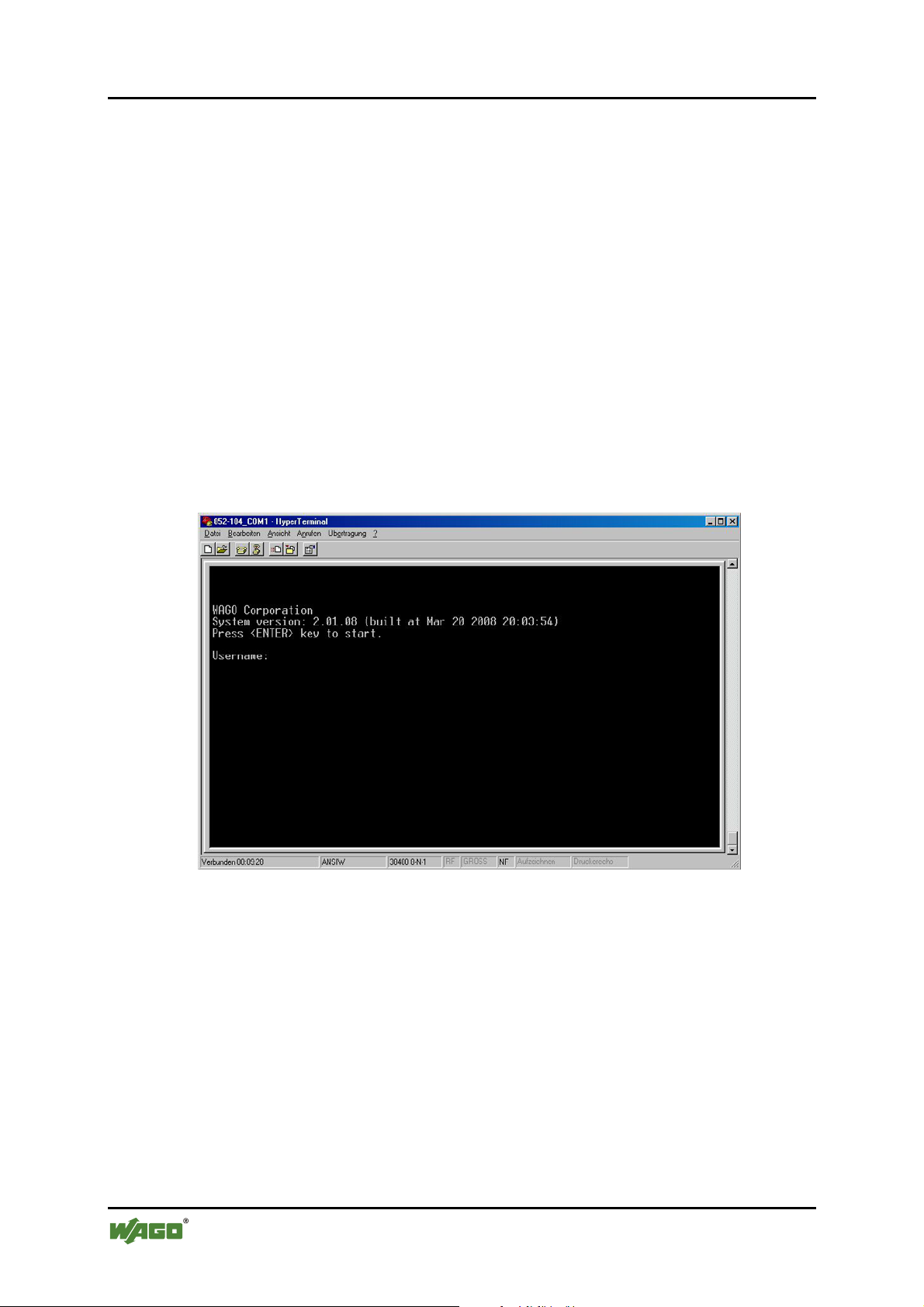
4 The default log in name is admin with no preset password.
The system provides both CLI and menu-driven user interfaces via console
or telnet. After you log into the system, you will see a welcome message as
below:
Figure 15: Interface
Manual
Version 1.1.3
Page 37
WAGO ETHERNET Accessories 852 Configuration 37
852-104 7-Port 100BASE-TX + 2-Slot 100BASE-FX Industrial Managed Switch
5 Type 1 to select CLI operations
After log-in, type the following command to change the device’s IP address,
Network Mask and Gateway Address:
set eth0 ip xxx.xxx.xxx.xxx
set eth0 netmask xxx.xxx.xxx.xxx
set eth0 gateway xxx.xxx.xxx.xxx
The xxx’s represent values between 0 and 255 and the user should enter their own
IP address in this form. The configuration program will not accept anything
outside this format. Remember to separate each part of the address with a period
(dot). For example:
• 852-104>set eth0 ip 192.168.0.200
After entering the new IP address, the system will confirm whether the operation
was successful.
6 The system will restart automatically
Pos: 25.7 /Dokumentation allgemein/Gliederungse lemente/---Seitenwechsel--- @ 3\mod_1221108045078_0.doc @ 21810 @ @ 1
When the address has been changed, please make a note of the new address, and
keep it in a safe place. With HyperTerminal, the command lines are the same as
that for telnet. Users can continue to use Hyper Terminal along with the
instructions given in part D. Otherwise, log out by typing exit and pressing the
[ENTER] key. Then, the user can choose to configure the Industrial Managed
Switch via HTTP web browser or telnet with Menu Driven or Command Line
interfaces.
Please note
IP addresses are unique. If an address isn’t available, please contact the system
administrator to apply for one.
Manual
Version 1.1.3
Page 38
38 Configuration WAGO ETHERNET Accessories 852
852-104 7-Port 100BASE-TX + 2-Slot 100BASE-FX Industrial Managed Switch
Pos: 25.8.1 /Serie 852 (Ethernet-Zubehör)/Konfi guration/B - Telnet/Interface Telnet @ 3\mod_122269566 5593_21.doc @ 22378 @ 2 @ 1
8.3 B – Menu driven User Interface via Telnet
This section gives a step by step guide to configuring the Industrial Managed
Switch management functions. A series of screen shots (SS#) and instructions
illustrates the main menu structure, and how it works.
1 Open a Command Prompt window and type
telnet xxx.xxx.xxx.xxx where the xxx’s represent the IP address.
As an example, we’ll continue to use the IP address configured in part A of
this manual: 192.168.0.200
2 Then press [ENTER] key to start.
SS1 – Log in
Figure 16: Log in
3 The default log in name is admin with no preset password.
The system provides both CLI and menu driven user interfaces via console
or telnet. After you log into the system, you will see a welcome message as
below:
Manual
Version 1.1.3
Page 39
WAGO ETHERNET Accessories 852 Configuration 39
852-104 7-Port 100BASE-TX + 2-Slot 100BASE-FX Industrial Managed Switch
SS2 – Welcome
Figure 17: Welcome screen
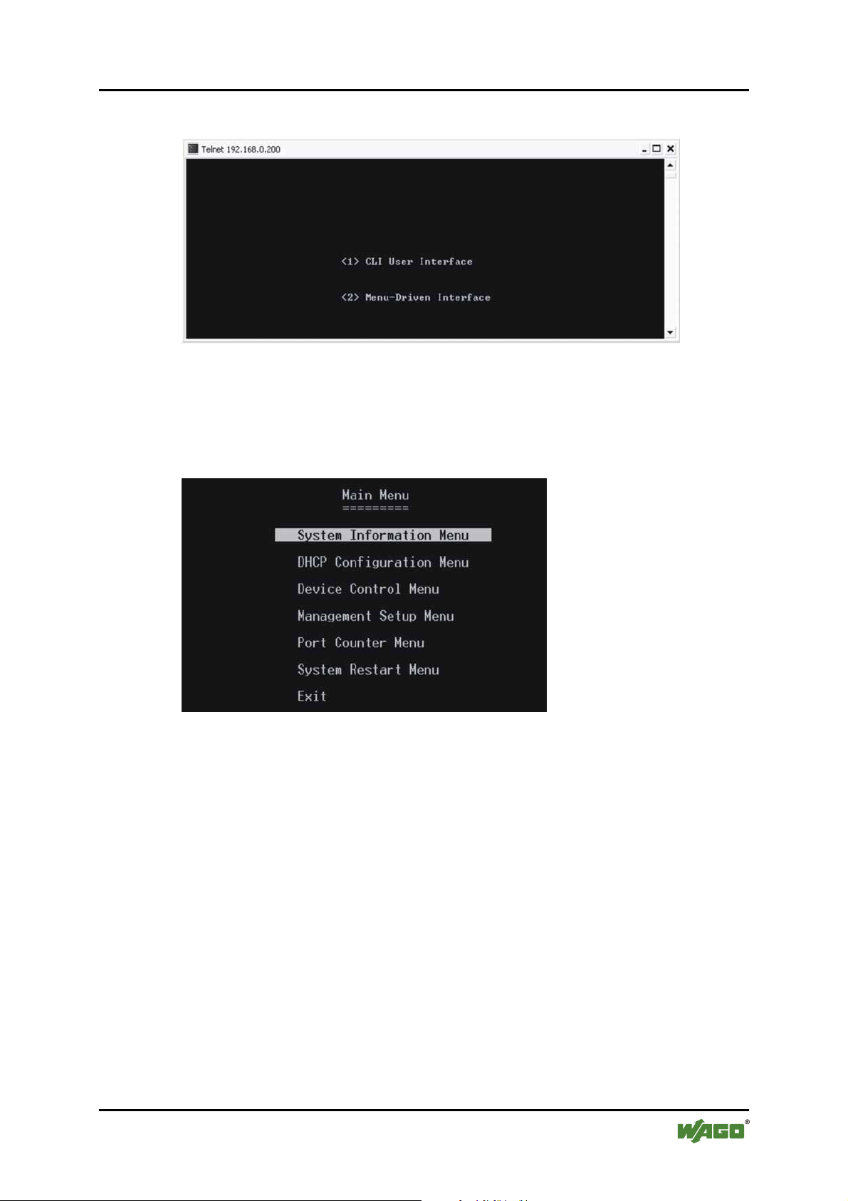
4 Select Menu Driven, the system will launch the following:
SS3 - Main Menu
Figure 18: Main menu
Use the [Tab] to move up and down the menu, and the [ENTER] key to select.
Choose the following operations from the main menu system. See description
below:
Manual
Version 1.1.3
Page 40
40 Configuration WAGO ETHERNET Accessories 852
852-104 7-Port 100BASE-TX + 2-Slot 100BASE-FX Industrial Managed Switch
Table 9: Main menu
Parameter Description
Systems
Information Menu
DHCP
Configuration
Provides default system information. i.e. IP Address,
Network Mask, Gateway, etc.
Disabled – or Enabled with DHCP Client State, DHCP
Leased Time in seconds, DHCP Expiry Time in seconds
Menu
Device Control
menu
Provides configuration options for ports, Bridge menu,
VLAN menu, and Jumbo Packet / Multicast Rate limit
menu
Management Setup
Menu
Port Counter Menu
System Restart
Menu
Provides SNMP, E-mail alarm Configurations menu and
firmware upload menu
Provides the ports status view at a glance
This menu provides options to the user for restarting the
switch through software and/or restore the factory default
settings
Exit
Return to Main Menu
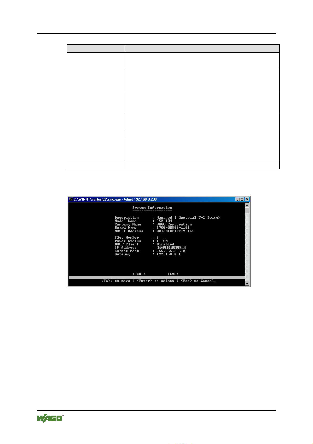
SS4 - System Information
Figure 19: System information
Use the [Tab] key to move from one field to the next and the [ENTER] key to get
a text prompt. Press [ENTER] to exit the field. Select [SAVE] after editing, or
[ESC] to return to the Main Menu system (all unsaved work will return to default
or the last saved values). Set IP Address, Subnet Mask, and Gateway on this page.
See descriptions below:
Manual
Version 1.1.3
Page 41
WAGO ETHERNET Accessories 852 Configuration 41
852-104 7-Port 100BASE-TX + 2-Slot 100BASE-FX Industrial Managed Switch
Table 10: System information
Parameter Description
Description
Model No
Company Name
Board Name
MAC Address
Slot number
Power status
IP Address
Provides description of the Switch
Shows Model No
Manufacturer’s Company Name
Information about the Board used in the Switch
Display MAC Address of the Switch
Total number of Switch’s fast Ethernet slots/ports
Display the primary and redundant power status
Display IP address of the switch. The user can change the
IP address as per requirement (Default: 192.168.0.254)
Subnet Mask
Show the subnet mask of the switch, which identifies the
host address bits used for routing to specific subnets. User
must use the appropriate subnet mask with the assigned IP
address (Default: 255.255.255.0)
Gateway
Gateway used to pass trap messages from the system’s
agent to the management station. User must assign the
gateway as per their network configurations (Default:
192.168.0.1)
Pos: 25.8.2 /Dokumentation allgemein/Gliederun gse lemente/---Seitenwechsel--- @ 3\mod_1221108045078_0.doc @ 21810 @ @ 1
Manual
Version 1.1.3
Page 42
42 Configuration WAGO ETHERNET Accessories 852
852-104 7-Port 100BASE-TX + 2-Slot 100BASE-FX Industrial Managed Switch
Pos: 25.8.3 /Serie 852 (Ethernet-Zubehör)/Konfi guration/B - Telnet/DHCP (Konfiguration Menu) @ 3\mod_122 2774563093_21.doc @ 22447 @ 3 @ 1
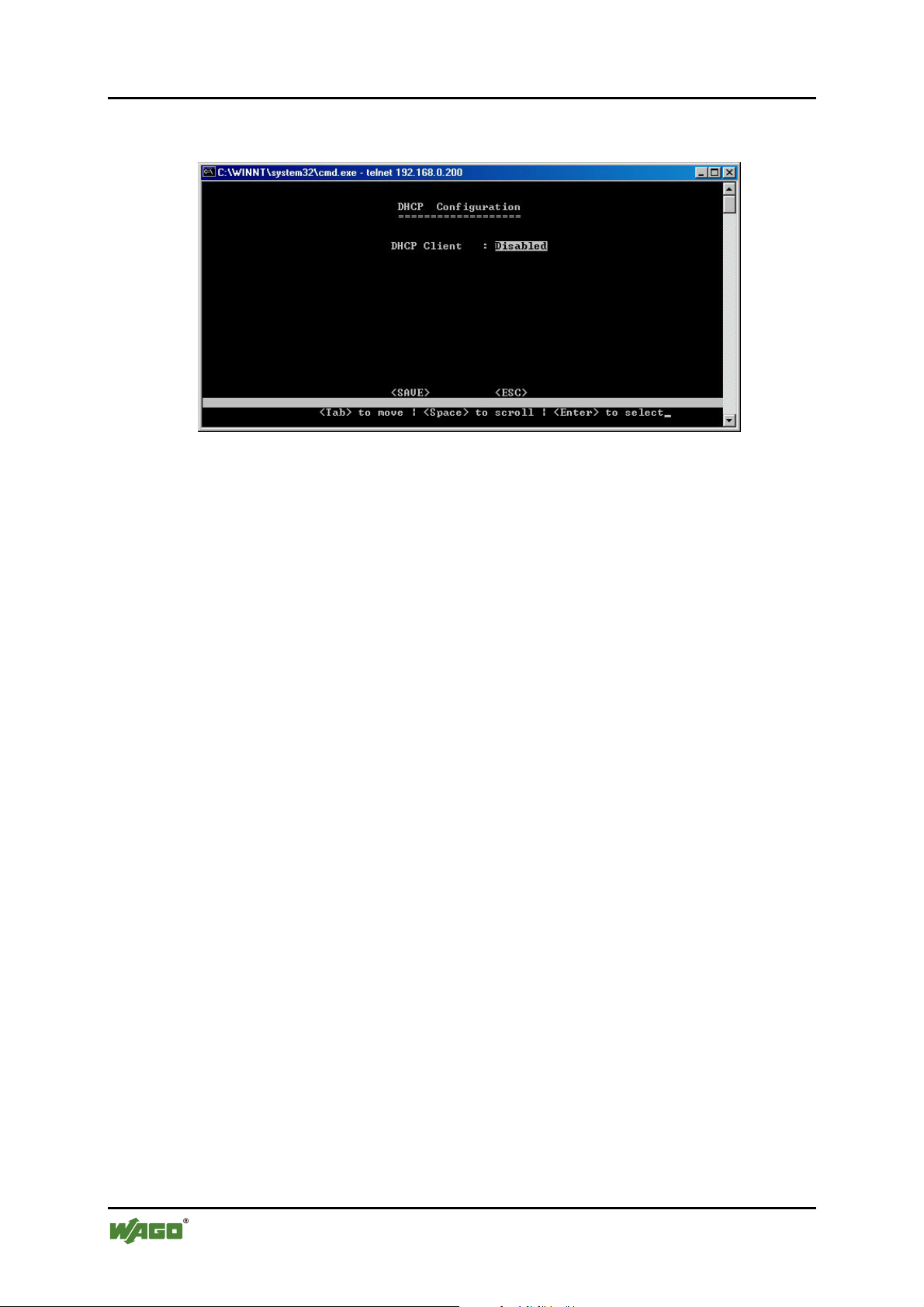
8.3.1 DHCP Configuration Menu
Figure 20: DHCP Configuration Menu
A choice of either “Disabled” or “Enabled” with DHCP Client State, DHCP
Leased Time in seconds and DHCP Expiry Time in seconds.
Pos: 25.8.4 /Dokumentation allgemein/Gliederun gse lemente/---Seitenwechsel--- @ 3\mod_1221108045078_0.doc @ 21810 @ @ 1
Manual
Version 1.1.3
Page 43
WAGO ETHERNET Accessories 852 Configuration 43
852-104 7-Port 100BASE-TX + 2-Slot 100BASE-FX Industrial Managed Switch
Pos: 25.8.5 /Serie 852 (Ethernet-Zubehör)/Konfi guration/B - Telnet/DCM (Device Control Menu) @ 3\mod_1222696 007750_21.doc @ 22381 @ 3 @ 1
8.3.2 Device Control Menu (DCM)
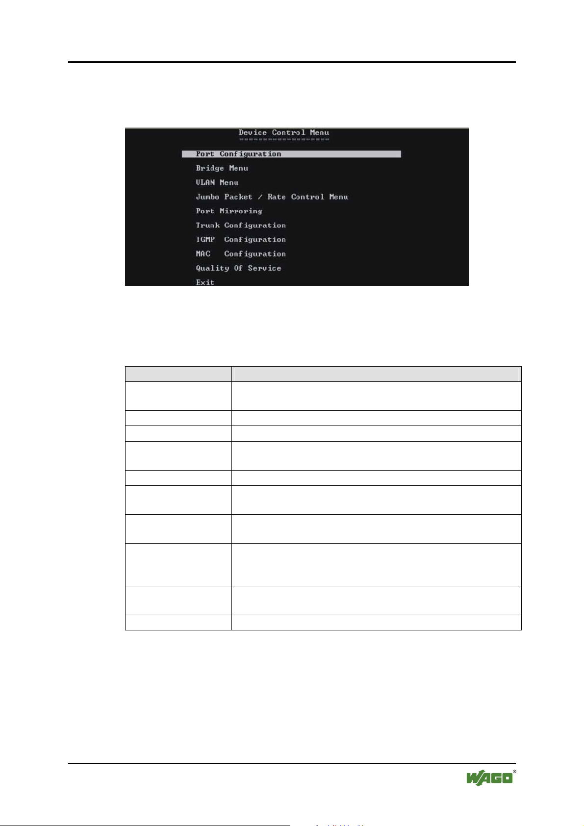
SS5 – Device Control Menu
Figure 21: Device Control Menu
Use the [Tab] to move up and down the menu, and the [ENTER] key to select
and unselect. Choose the following operations from the menu system.
Table 11: Device Control Menu
Parameter Description
Port Configurations
Menu
Bridge Menu
VLAN Menu
Jumbo Packet /
Rate Control Menu
Port Mirror
Trunk
Use this menu to configure various parameters for each port
of the Switch.
Use this menu for Bridge configurations.
Use this menu to configure port based or tag based VLANs.
Users can define Jumbo Packet limit and bandwidth/data
rate control for each port.
Options to select a port for mirroring to monitor the traffic.
Configure up to 4 trunk groups.
Configuration
IGMP
Configure IGMP snooping, query and check group status.
Configuration
MAC
Configuration
Here you can check the MAC Table Status, lock the MAC
Address Learning and do Static Unicast MAC
Configuration and Mac Limit Configuration
Quality Of Service
Set the QoS Base Configuration, Tag Priority Table and IP
ToS Priority Table
Exit
Return to Main Menu
Manual
Version 1.1.3
Page 44
44 Configuration WAGO ETHERNET Accessories 852
852-104 7-Port 100BASE-TX + 2-Slot 100BASE-FX Industrial Managed Switch
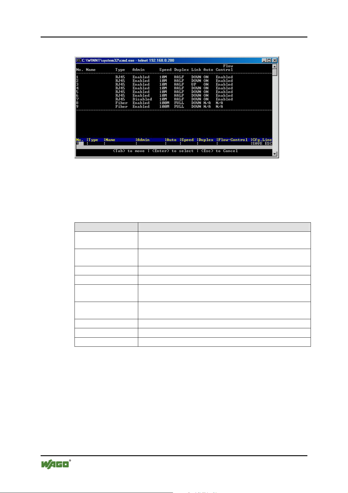
SS6 – (DCM)/Port Configuration Menu
Figure 22: Port Configuration Menu
Use the [Tab] key to move from one field to next and the [ENTER] key to select
and unselect. Press [ENTER] to exit the field. Select [SAVE] after editing, or
[ESC] to return to the Main Menu system (all unsaved work will return to default
or last saved values).
Pos: 25.8.6 /Dokumentation allgemein/Gliederun gse lemente/---Seitenwechsel--- @ 3\mod_1221108045078_0.doc @ 21810 @ @ 1
Table 12: Port Configuration Menu
Parameter Description
Port No.
Press [Enter] and [Port No.] and [ENTER] and [Tab] in
settings panel.
Name
Assign a name to each port to keep record of your
connections.
Type
Admin
Speed
Type of port connector (A choice of fiber or RJ-45)
Enable or disable admin configurations.
Provides information on speed at which ports are operating
User can set the speed for RJ-45 ports (10 … 100 Mbps).
Duplex
Provides information on Duplex Status.
User can select half / full duplex modes.
Link (status only)
Auto
Flow Control
Provides information on link status.
Enable / Disable Auto negotiation on copper ports.
Disable or Enable for RJ-45 ports.
Manual
Version 1.1.3
Page 45
WAGO ETHERNET Accessories 852 Configuration 45
852-104 7-Port 100BASE-TX + 2-Slot 100BASE-FX Industrial Managed Switch
Pos: 25.8.7 /Serie 852 (Ethernet-Zubehör)/Konfi guration/B - Telnet/DCM / Bridge Menu @ 3\mod_1222850941421_2 1.doc @ 22699 @ 3 @ 1
8.3.3 (DCM)/Bridge Menu
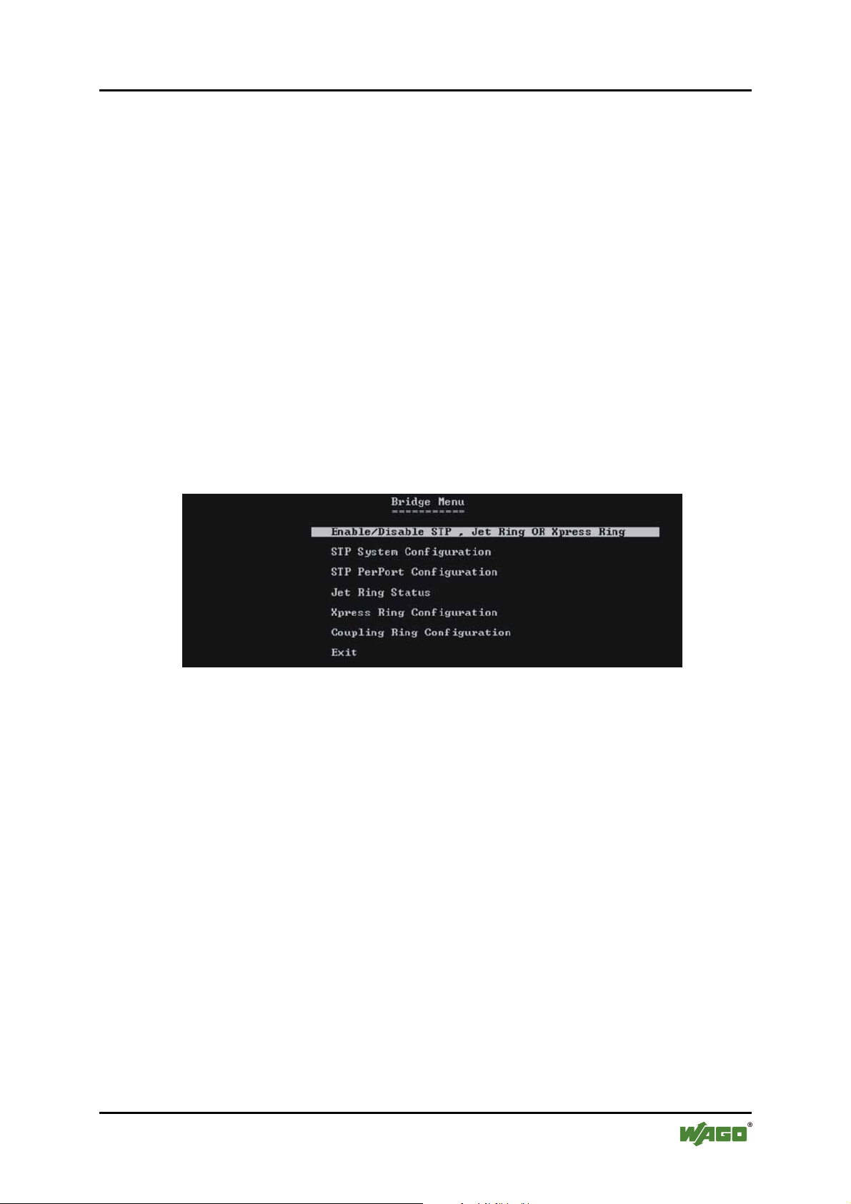
The Bridge Menu is used to Enable/Disable STP (Spanning Tree Protocol
Algorithm), JET Ring or Xpress Ring, as well as to configure the STP settings if
STP is enabled.
If Jet Ring is enabled it offers a fast recovery time of less than 300 ms in case a
node goes down in the ring. Xpress Ring offers a very fast recovery time of less
than 50 ms.
The Spanning Tree Algorithm is used for detecting and disabling network loops,
and to provide backup links between switches, bridges and routers. This allows
the switch to communicate and interact with other bridging devices (i.e. STPcompliant devices) in a network to ensure that only one route exists between any
two stations, and provide redundant or backup links that automatically take over
when a primary link fails.
SS7 – (DCM)/Bridge Menu
Figure 23: Bridge Menu
Manual
Version 1.1.3
Page 46
46 Configuration WAGO ETHERNET Accessories 852
852-104 7-Port 100BASE-TX + 2-Slot 100BASE-FX Industrial Managed Switch
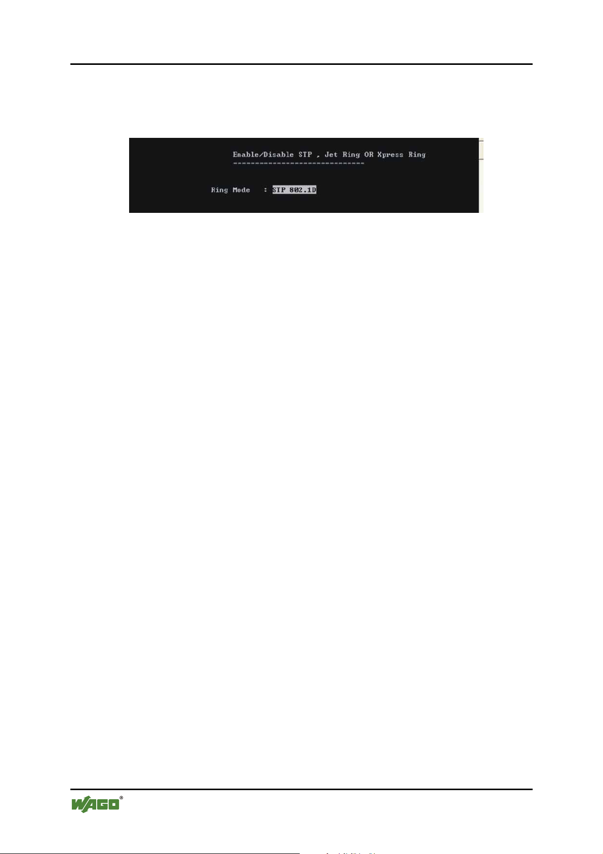
SS8 – (DCM)/Bridge/Enable/Disable STP, Jet Ring or Xpress Ring
Users can Enable/Disable Spanning Tree Protocol, Jet Ring or Xpress Ring as per
their network needs. Select the option to choose the parameters.
Figure 24: Enable/Disable STP
The default value is Disabled. Use the [Tab] key to move from one field to next
and the [Enter] key to select and unselect. Press [Enter] to exit the field. Select
[SAVE] after editing, or [ESC] to return to the Main Menu system (all unsaved
configurations will return to default or last saved values.
Manual
Version 1.1.3
Page 47
WAGO ETHERNET Accessories 852 Configuration 47
852-104 7-Port 100BASE-TX + 2-Slot 100BASE-FX Industrial Managed Switch
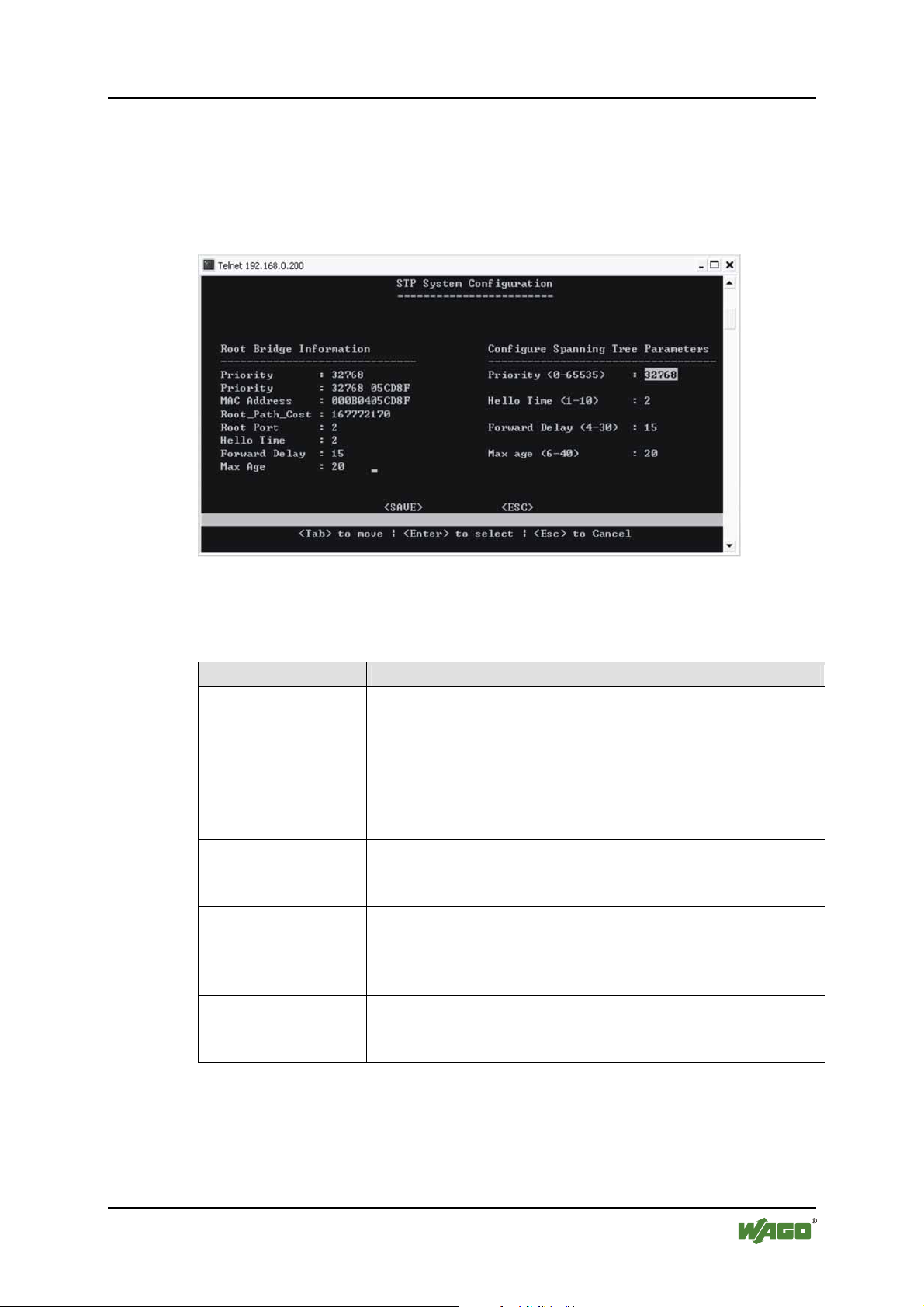
SS9 – (DCM)/Bridge/STP System Configuration:
Use this option to configure the STP parameters. Before moving to this menu,
make sure you select STP 802.1D mode in previous menu screen (Enable/Disable
STP, Jet Ring or Xpress Ring). Otherwise, you wouldn’t be able to configure the
values.
Figure 25: STP System Configuration
On the left side of the window, root bridge information is displayed.
Table 13: STP System Configuration
Parameter Description
Bridge Priority
Set the bridge priority. The limit is given between 0 (the
highest priority) and 65535 (the lowest priority).
Bridge priority is used in selecting the root device, root
port, and designated port. The device with the highest
priority becomes the STP root device. However, if all
devices have the same priority, the device with the lowest
MAC address will then become the root device.
Hello Time
Time interval (in seconds) at which the root device
transmits a configuration message.
The limit given is from 1 … 10 s.
Forward Delay
Set Forward Delay. The limit given is from 4 … 30 s. This
is the maximum time (in seconds) the root device will wait
before changing states (i.e., listening to learning to
forwarding).
Max. Age
Set the (maximum age) waiting time for receiving packets
before attempting to reconfigure the link. The limit given is
from 6 … 40 s.
Manual
Version 1.1.3
Page 48
48 Configuration WAGO ETHERNET Accessories 852
852-104 7-Port 100BASE-TX + 2-Slot 100BASE-FX Industrial Managed Switch
SS10 – (DCM)/Bridge/STP Per-Port Configurations
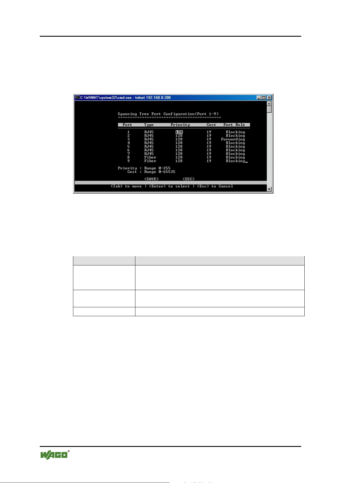
STP allows the Switch to assign a priority status to each of its ports, with respect
to other networking nodes in the network. In other words, STP determines the best
route for data to flow, given the priority level of each node on the network. Ensure
that this function is activated to avoid collisions and when setting up backup links.
Figure 26: STP per Port Configuration
Use the [Tab] key to move from one field to the next and the [Enter] key to
select and unselect. Press [Enter] to exit the field. Select [SAVE] after editing, or
[ESC] to return to the Main Menu system (all unsaved work will return to default
or last saved values).
Table 14: STP per Port Configuration
Parameter Description
Port Type Priority
Set the priority of each port. The limit given is from
1 … 255. The default priority is set to 128 – the midpoint of
this limit.
Cost
Set the cost assigned to each port. This will determine the
route of information flow.
Port Role
Displays the role of each port (Forwarding or Blocking).
Manual
Version 1.1.3
Page 49
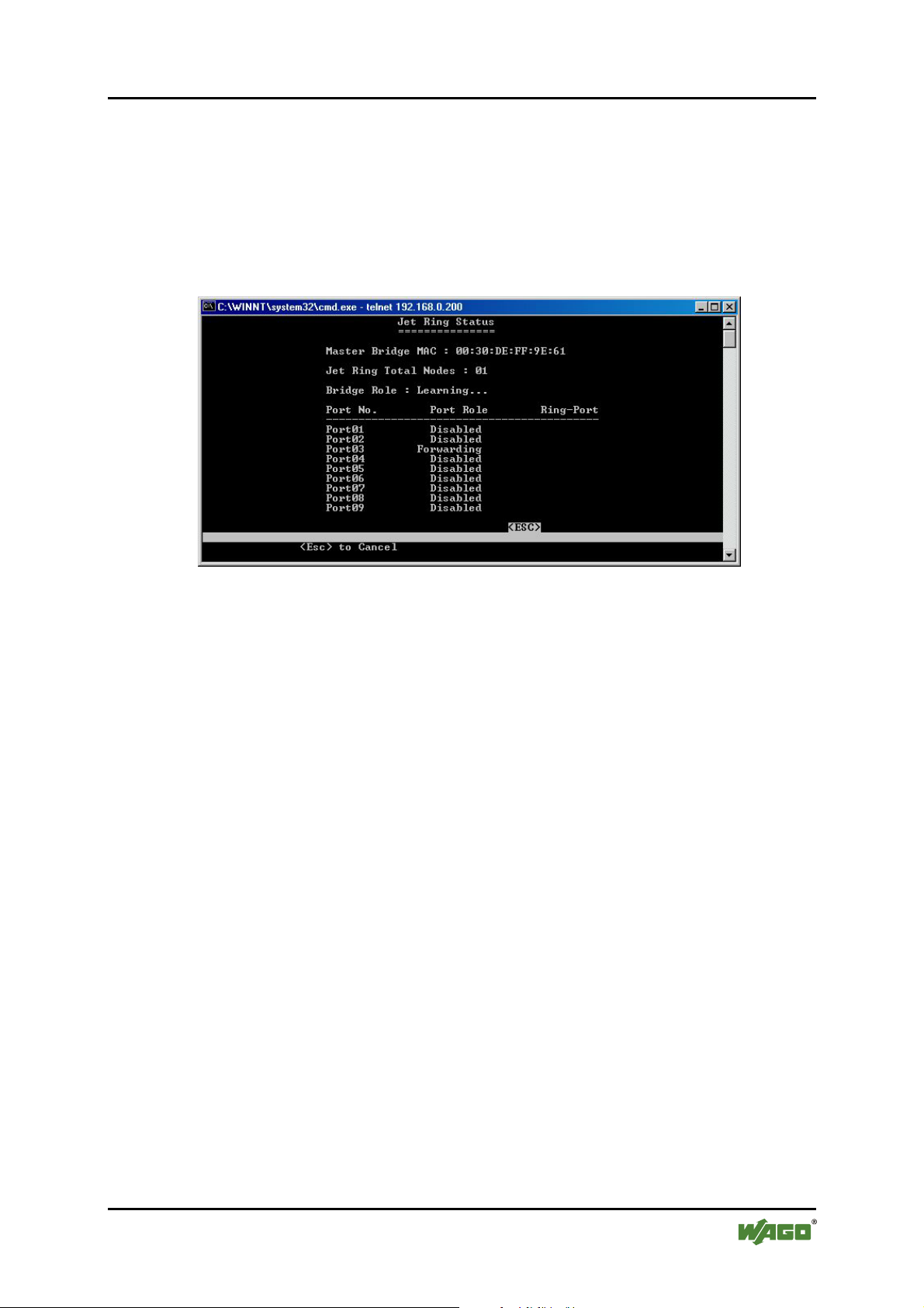
WAGO ETHERNET Accessories 852 Configuration 49
852-104 7-Port 100BASE-TX + 2-Slot 100BASE-FX Industrial Managed Switch
SS11 – (DCM)/Bridge/Jet Ring Status
If Jet Ring is enabled, the user can view the Jet Ring status. The Industrial
Managed Switch will automatically detect which port is attached to othe r
Industrial Managed Switches (or other Jet Ring-enabling switches) to establish the
Jet Ring. The user can see how many nodes are connected in the ring and which
node is working as Master, Arbiter or member. There are also descriptions of the
role of each port.
Figure 27: JetRing Status
Manual
Version 1.1.3
Page 50
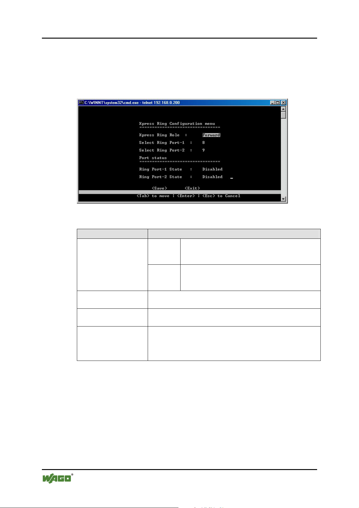
50 Configuration WAGO ETHERNET Accessories 852
852-104 7-Port 100BASE-TX + 2-Slot 100BASE-FX Industrial Managed Switch
SS12 – (DCM)/Bridge/Xpress Ring Configuration
Once Xpress Ring (sometimes called Jet Ring Plus) is enabled, the user can
configure the Xpress Ring. The user can select the role of the switch in the Xpress
Ring (Arbiter or Forward) and select which ports will be part of the Xpress
Ring.
Figure 28: XpressRing Configuration
Pos: 25.8.8 /Dokumentation allgemein/Gliederun gse lemente/---Seitenwechsel--- @ 3\mod_1221108045078_0.doc @ 21810 @ @ 1
Table 15: XpressRing Configuration
Port Configuration
Xpress Ring Role
Arbiter
The Switch which receives status reports
submitted from other Switches of the ring and
decides the ring recovery behaviours.
Forward
The Switch which is not the Arbiter of the ring
and will forward the received status reports on
the other side of ring ports.
Select Ring Port-1
The first ring port with the link composing part of the
Xpress Ring.
Select Ring Port-2
The second port with the link composing part of the
Xpress Ring.
Port status
Display the ring port statuses as
- Forwarding for packet transmitting and receiving
status, or
- Blocking for port disabled or link down status.
Manual
Version 1.1.3
Page 51
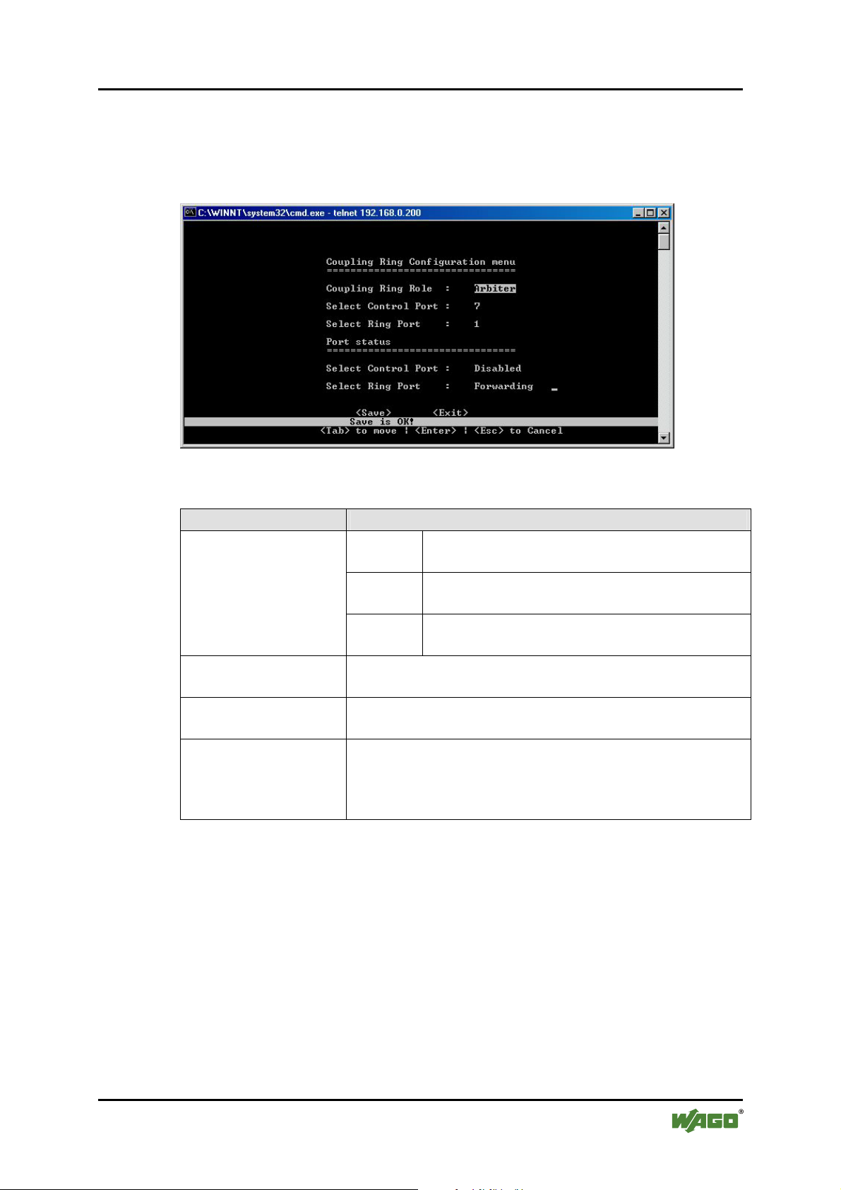
WAGO ETHERNET Accessories 852 Configuration 51
852-104 7-Port 100BASE-TX + 2-Slot 100BASE-FX Industrial Managed Switch
Pos: 25.8.9 /Serie 852 (Ethernet-Zubehör)/Konfi guration/B - Telnet/Coupling Ring Menu @ 3\mod_122269645198 4_21.doc @ 22387 @ 3 @ 1
8.3.4 Coupling Ring
Set Coupling Ring configurations to all Switches of either side of two
interconnected Xpress Rings.
Figure 29: Coupling Ring
Pos: 25.8.10 /Dokumentation allgemein/Glieder ungs elemente/---Seitenwechsel--- @ 3\mod_1221108045078_0.doc @ 21810 @ @ 1
Table 16: XpressRing Configuration
Port Configuration
Coupling Ring Role
Arbiter
The Switch with the backup secondary link to
the other Xpress Ring.
Master
The Switch with the primary link to the other
Xpress Ring.
Normal
The Switches not with the links connecting to
other Xpress Ring.
Select Control Port
The Control Port of Coupling Ring Master Switch or
Arbiter Switch for communication with each other.
Select Ring Port
The Ring Port of Coupling Ring Master Switch or Arbiter
Switch for connection to the peer coupled Xpress Ring.
Port status
Display the port status of Control Port or Ring Port as
- Forwarding for packet transmitting and receiving
status, or
- Blocking for port disabled or link down status.
Manual
Version 1.1.3
Page 52
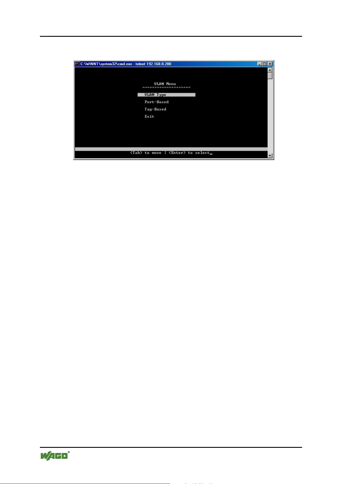
52 Configuration WAGO ETHERNET Accessories 852
852-104 7-Port 100BASE-TX + 2-Slot 100BASE-FX Industrial Managed Switch
Pos: 25.8.11 /Serie 852 (Ethernet-Zubehör)/Konfi guration/B - Telnet/DCM / VLAN Menu @ 3\mod_1222696569250_21.d oc @ 22390 @ 344 @ 1
8.3.5 (DCM)/VLAN (Virtual Local Area Networks) Menu
Figure 30: VLAN Menu
A VLAN is a network of computers behaving as though they are connected to the
same LAN segment, even though their physical location may be on a different
LAN altogether. VLANs are configured through software rather than hardware,
which make them extremely flexible.
Some of the advantages of VLANs are:
• When a computer is physically moved to another location, it can stay on the
same VLAN without any hardware reconfiguration because VLANs are not
limited by hardware constraints.
• VLANs can be configured to define a network into various logical
configurations. For example, VLANs can define a network by application.
In this scenario, a company might create one VLAN for multimedia users
and another for e-mail users.
• VLANs can also define a network by department. For example, a company
might have one VLAN for its Engineering Department, another for its
Marketing Department, and another for its Sales Dept.
• VLANs can also be set up according to the organization’s internal structure.
For example, the company president might have his/her own VLAN, the
executive staff might have a different VLAN, and the remaining employees
might have yet another VLAN.
As these examples show, VLANs offer unparalleled flexibility. The following
section describes how VLANs can be deployed using the Switch.
Manual
Version 1.1.3
Page 53
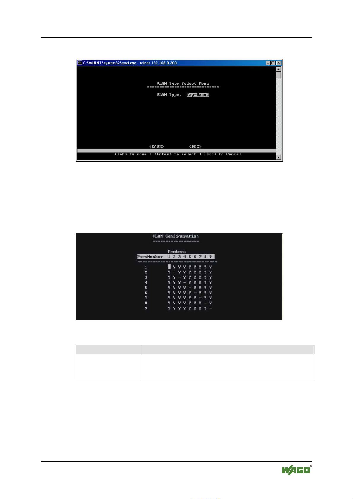
WAGO ETHERNET Accessories 852 Configuration 53
852-104 7-Port 100BASE-TX + 2-Slot 100BASE-FX Industrial Managed Switch
8.3.5.1 VLAN Type Select Menu
Figure 31: VLAN Type Select Menu
Disable VLAN or select Port-based VLAN or Tag based VLAN.
SS13 – Port based VLAN configuration
The following is the menu screen for port based VLAN configuration:
Figure 32: VLAN Configuration
Table 17: VLAN Configuration
Parameter Description
Port ID Members
Set the VLAN association of one port to another. Blank
checks mean no VLAN association. The default is that all
ports are associated. Conversely, all ports can be isolated.
Use the [Tab] key to move from one field to the next and the [Enter] key to
select and unselect. Press [Enter] to exit the field. Select [SAVE] after editing, or
[ESC] to return to the Main Menu system (all unsaved work will return to default
or last saved values).
Manual
Version 1.1.3
Page 54

54 Configuration WAGO ETHERNET Accessories 852
852-104 7-Port 100BASE-TX + 2-Slot 100BASE-FX Industrial Managed Switch
8.3.5.2 Tag-based VLANs
The concepts of tag-based VLAN
Tag-based VLAN is the standard implementation of IEEE802.1Q VLAN. With
the Industrial Managed Switch set as a tag-based VLAN switch, every port has the
following:
PVID
Port VLAN ID number, generally referring to the VLAN, which the connected
non-802.1Q-aware device (like a Device Server or Industrial Computer) belongs
to. This PVID can be configured in the menu Port Information.
Priority
Priority of the port and the non-802.1Q packets received on the port – generally
from a non-802.1Q-aware device. (Port Info menu)
Participating VLANs
The VID-tagged packets, which are allowed to flow in or out of the port. A port
may participate in multiple VLANs, like an uplink port connected to another
switch, which will transfer the packets from various devices belonging to different
VLANs into the network. (BUT, generally, a port connected to a peripheral non-
802.1Q device can only participate in 1 VLAN, the same VLAN ID that is
selected for that port in the “Port Info” menu). The participating VLANs can be
configured in the menu Add VLAN Group.
If the port is set in the Add VLAN Group menu as a Tagged Port, all packets
flowing out of the port will be tagged frames to an 802.1Q switch or device.
If the port is set as an Untagged Port, all packets out of the port will be untagged
frames (stripped of their tags at port) to a non-802.1Q device, like an industrial
computer.
When a packet is received (ingress) on the port, it is filtered to be dropped or
forwarded according to the user-specified rule (configured on menu “Port
Information”) for ingress-filtering untagged frames and tagged frames that are not
members of the receiving port’s participating VLANs (configured on menu Add
VLAN Group).
If the packet is forwarded, the untagged frames, generally from a non-802.1Qaware peripheral or device, are tagged with the PVID and Priority that were
assigned to the Ingress port.
Manual
Version 1.1.3
Page 55

WAGO ETHERNET Accessories 852 Configuration 55
852-104 7-Port 100BASE-TX + 2-Slot 100BASE-FX Industrial Managed Switch
The untagged packets received by an 802.1Q Switch in this way become tagged
frames. The tagged frames received on the ingress port are kept unchanged if it’s
not dropped.
Next, the Industrial Managed Switch switches the frame into the egress port that is
a participant of that specific VLAN.
For example: If the ingress is from a peripheral device linked to a downlink port
on a switch with only one uplink port and the frame is addressed to a device on
another switch, the frame would be switched to egress out of the uplink port – and
this UPlink port would be set to participate in the VLANs of all the DOWNlink
ports and forward all their traffic.
If the egress port is an “untag” port (normally a port linked to a peripheral, non-
802.1Q device that does not accept tagged frames), the VID and priority fields
will be stripped off (untagged) from the frame and then transmitted out of the
egress port.
A previously tagged frame is simply kept unchanged when it is sent out from a
“tagging” egress port, generally to a 802.1Q switch or a standard VLAN-aware
device.
Manual
Version 1.1.3
Page 56
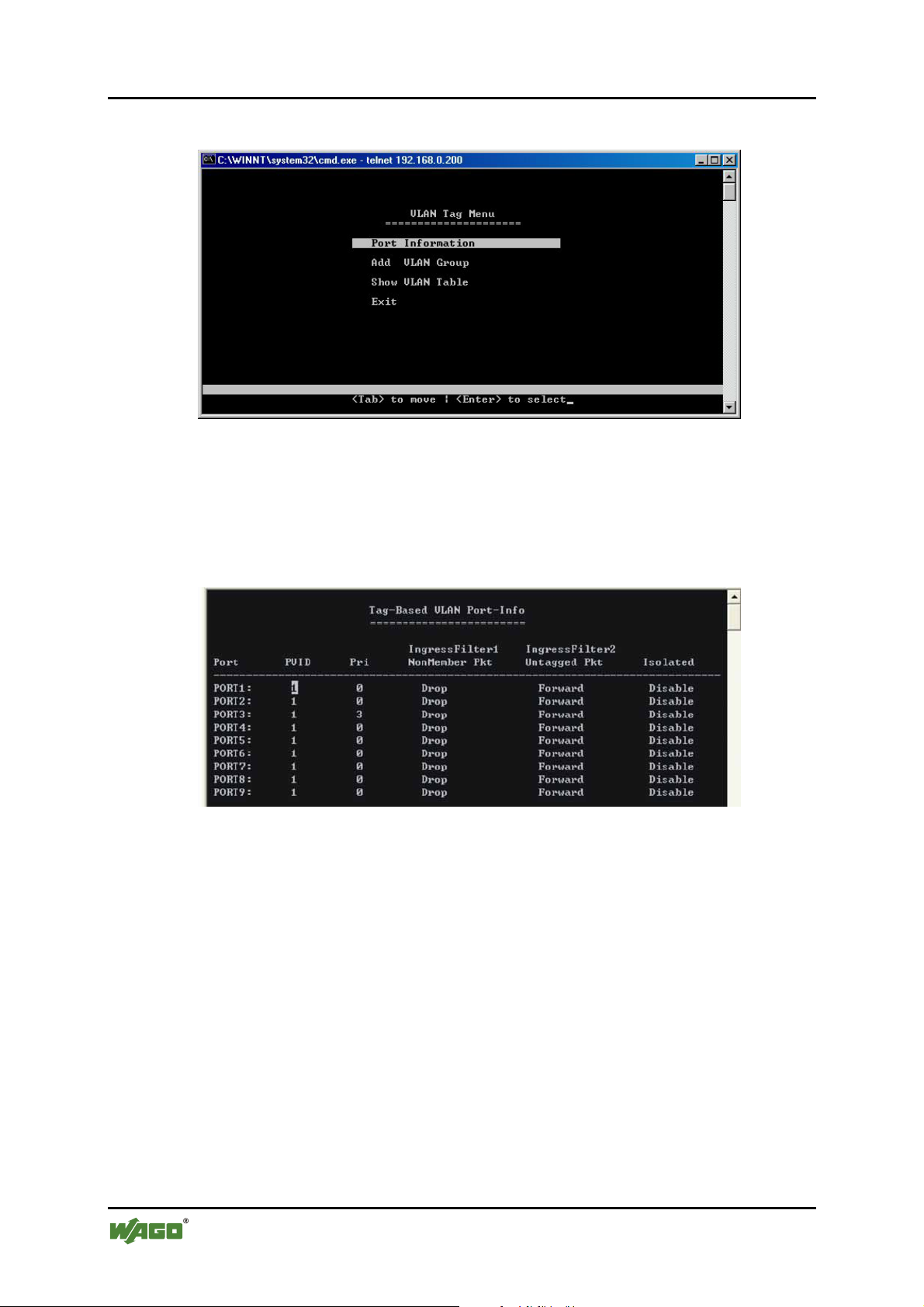
56 Configuration WAGO ETHERNET Accessories 852
852-104 7-Port 100BASE-TX + 2-Slot 100BASE-FX Industrial Managed Switch
VLAN Tag Menu
Figure 33: VLAN Tag Menu
SS14 – VLAN Tag-based Port (Ingress) – Info
Here is the above-mentioned menu screen for configuring the TAG-based VLAN
port settings (INGRESS Behavior).
Figure 34: Tag-Based VLAN Port-Info
Manual
Version 1.1.3
Page 57
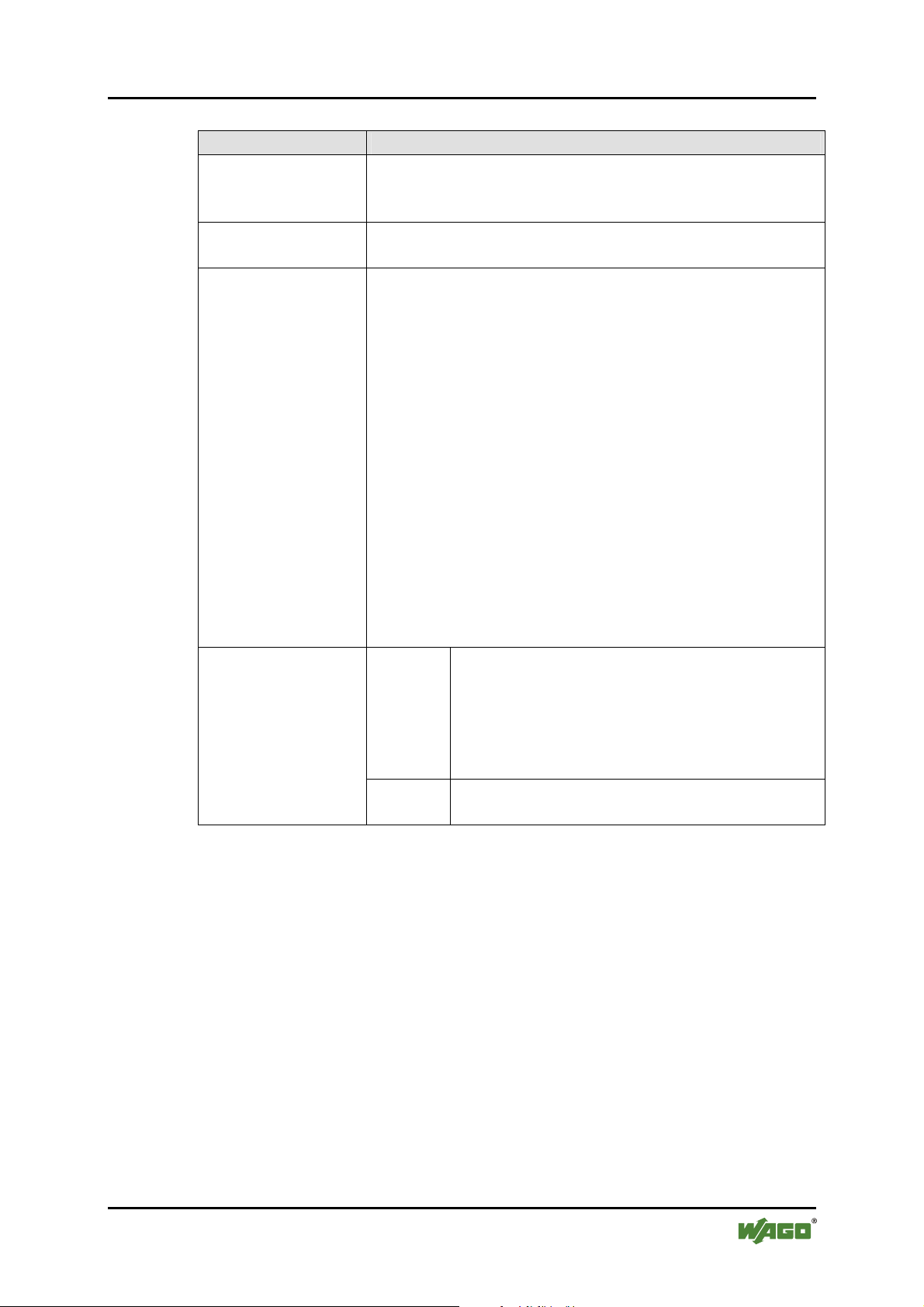
WAGO ETHERNET Accessories 852 Configuration 57
852-104 7-Port 100BASE-TX + 2-Slot 100BASE-FX Industrial Managed Switch
Table 18: Tag-Based VLAN Port-Info
Parameter Description
VID
Set the VLAN ID. The limit given is between 1 and 4095.
The VLAN ID is assigned to all untagged frames received
on this port.
Priority
Set VLAN Priority. The limit given is between 0 … 7.
0 is the lowest priority and 7 is the highest priority.
Ingress Filter 1
(Non-Member) and
Filter 2 (Untagged)
Non-Member (1): Forward
Untagged (2): Forward
• Forward the VLAN-tagged frames which are not
members of any VLAN in which the port is
participating, and forward all untagged frames.
Non-Member (1): Drop
Untagged (2): Forward
• Drop the VLAN-tagged frames which are not
members of any VLAN of which the port is
participating, and forward all untagged frames.
Isolated
Non-Member (1): Drop
Untagged (2): Drop
• Drop the VLAN-tagged frames which are not
members of any VLAN of which the port is
participating, and drop all untagged frames.
Enable
The port is isolated. Isolated ports belonging to
the same VLAN do not communicate with each
other – this is generally set for security reasons.
The isolated ports communicate only with the
trunk ports, which should NOT be set as
“isolated”.
Disable
The port is not isolated and can communicate
with all ports of the VLANs.
Manual
Version 1.1.3
Page 58
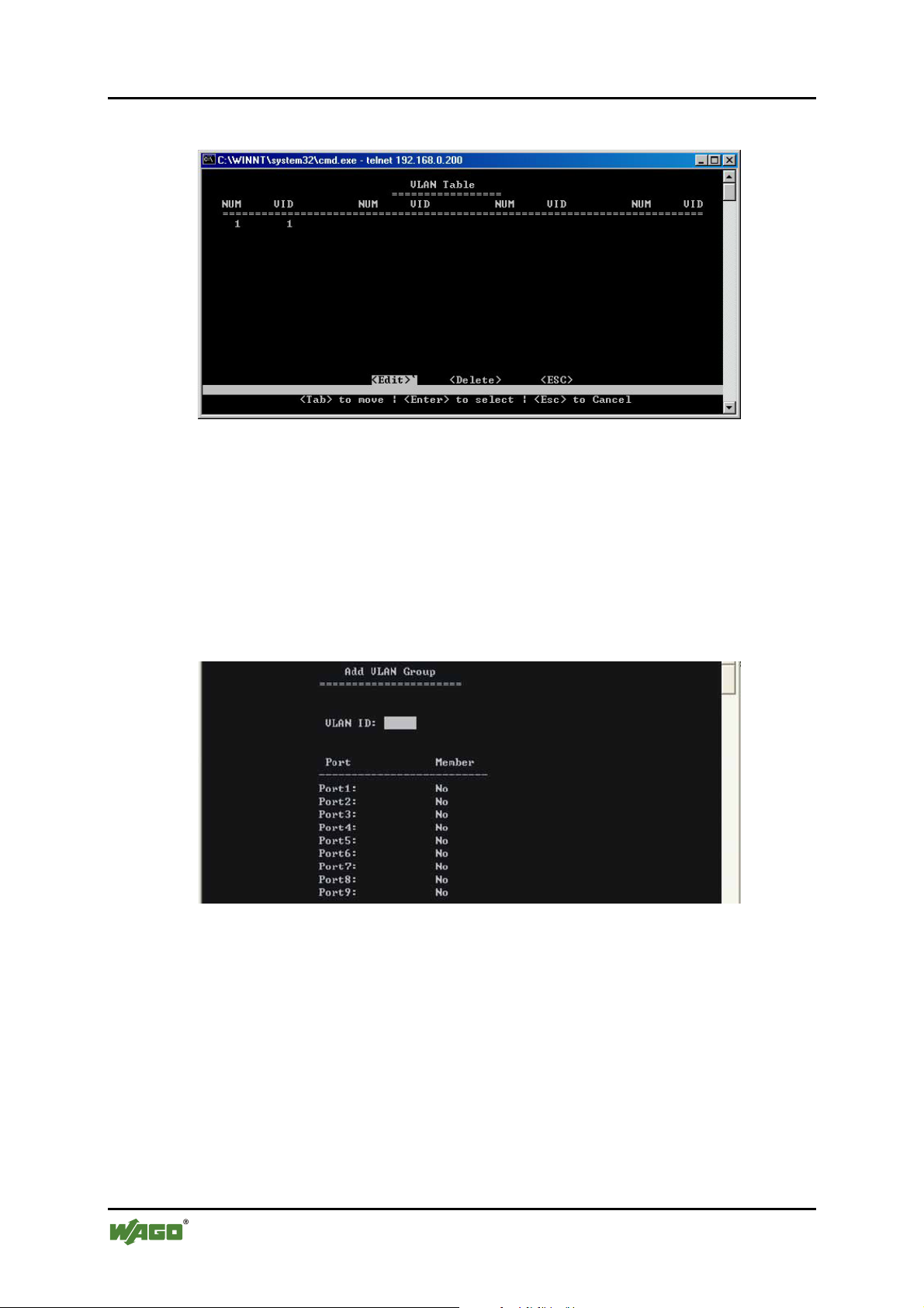
58 Configuration WAGO ETHERNET Accessories 852
852-104 7-Port 100BASE-TX + 2-Slot 100BASE-FX Industrial Managed Switch
VLAN Table
Figure 35: VLAN Table
SS15 – Tag-based/Adding VLAN groups (port EGRESS behavior)
Type in VLAN ID number and at each port select “No” (not a member of this
specific VLAN – drop packet), “Untagged” (member of VLAN, take tag away so
that computer can read) or “Tagged” (keep tag on packet – only for uplink port).
The menu Show VLAN Table shows all VLANs at a glance and enables the user
to edit these VLANs.
Figure 36: Add VLAN Group
Manual
Version 1.1.3
Page 59
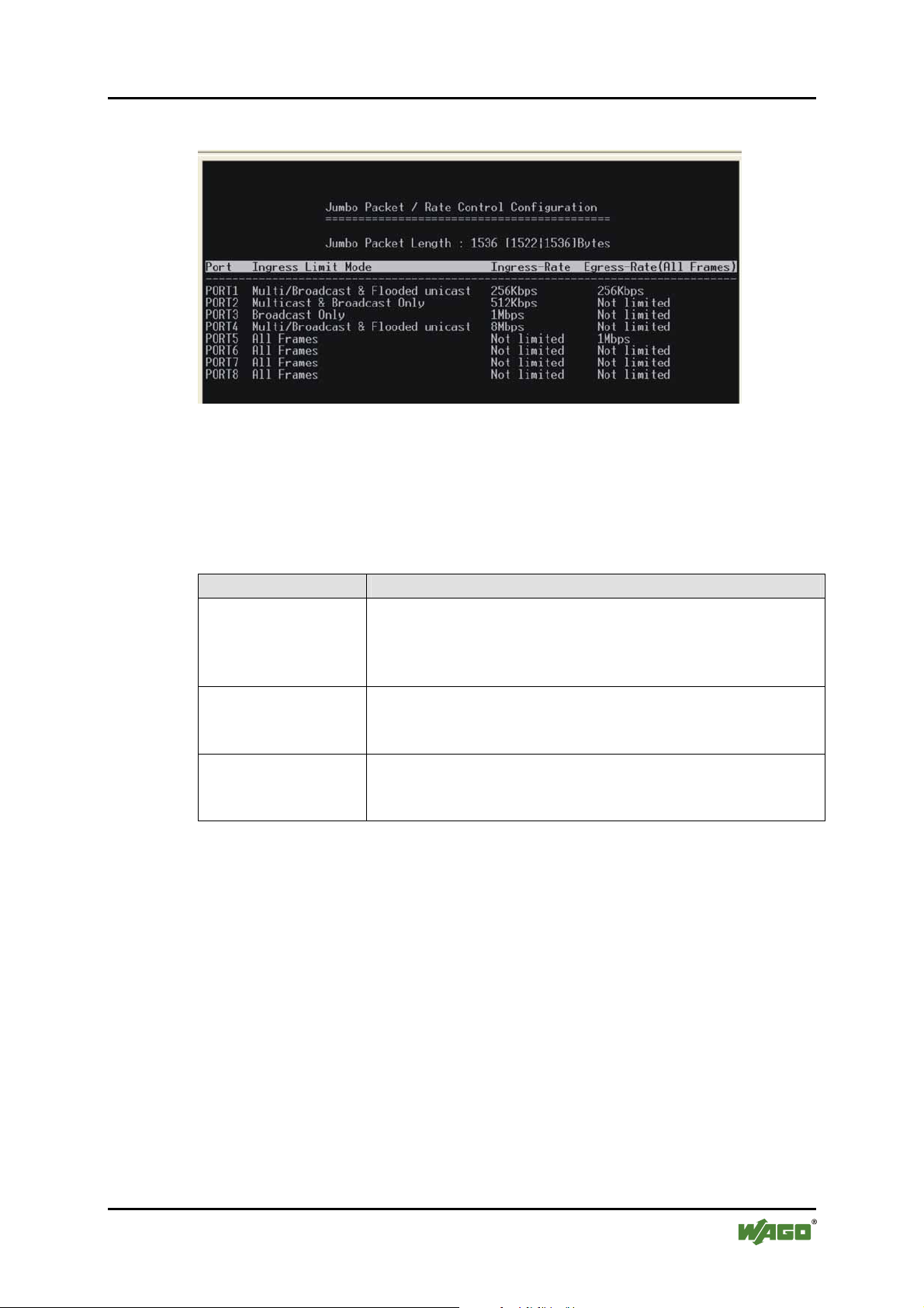
WAGO ETHERNET Accessories 852 Configuration 59
852-104 7-Port 100BASE-TX + 2-Slot 100BASE-FX Industrial Managed Switch
SS16 – (DCM)/Jumbo Packet or Rate Control Configuration
Figure 37: Jumbo Packet
Use the [Tab] key to move from one field to the next and the [Enter] key to
select and unselect. Press [Enter] to exit the field. Select [SAVE] after editing, or
[ESC] to return to the Main Menu system (all unsaved work will return to default
or last saved values).
Table 19: Jumbo Packet
Parameter Description
Jumbo Packet
Length
Select the size of packets:
1535 – For double-tagged packets or jumbo packets
1522 – For normally tagged packets. 1518 bytes are
actually allowed for untagged packets.
Ingress Limit Mode
Users can select the type of frames allowed from the port
(All Frames, Broadcast Only, Multicast & Broadcast Only,
Multi/Broadcast & Flooded Unicast).
Ingress / Egress
Rate
Assign the Ingress and Egress rates to and from the ports
(128 Kbps, 256 Kbps, 512 Kbps, 1 Mbps, 2 Mbps, 4 Mbps,
8 Mbps).
Manual
Version 1.1.3
Page 60
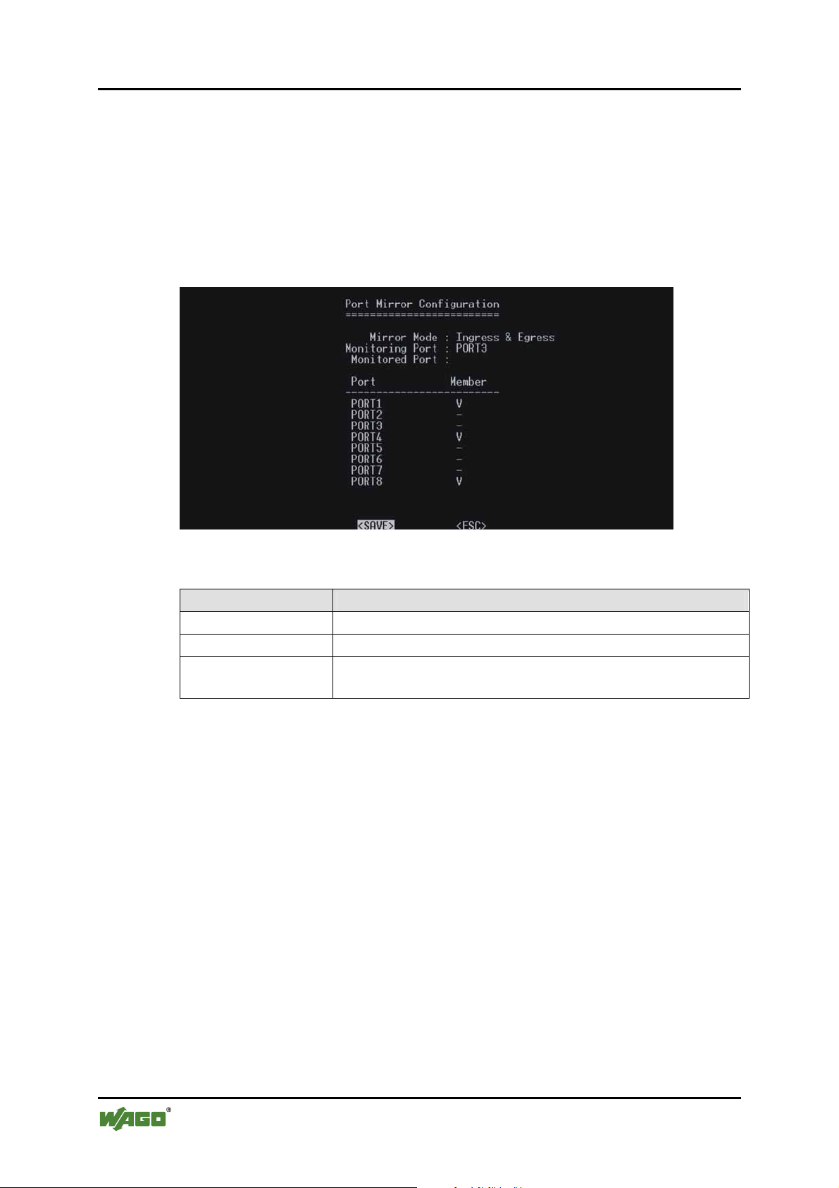
60 Configuration WAGO ETHERNET Accessories 852
852-104 7-Port 100BASE-TX + 2-Slot 100BASE-FX Industrial Managed Switch
SS17 – (DCM)/Port Mirroring
port. It allows the network administrator to “sniff” the observed port and thus
keep tabs on network activity.
Use the [Tab] key to move from one field to the next and the [Enter] key to
select and unselect. Press [Enter] to exit the field. Select [SAVE] after editing, or
[ESC] to return to the Main Menu system (all unsaved work will return to default
or last saved values).
Figure 38: Port Mirror Configuration
Table 20: Port Mirroring
Parameter Description
Mirror Mode
Monitoring Port
Monitored Port /
Select mirror mode (Disable, Ingress & Egress, Ingress)
User can select the port number that will do monitoring
Select the port/s that need to be monitored
Member
Manual
Version 1.1.3
Page 61
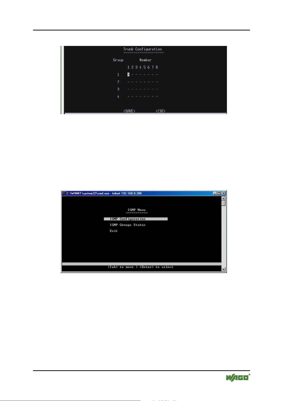
WAGO ETHERNET Accessories 852 Configuration 61
852-104 7-Port 100BASE-TX + 2-Slot 100BASE-FX Industrial Managed Switch
SS18 – (DCM)/Trunk Configuration
Figure 39: Trunk Configuration
Use the usual keys to configure up to four trunk groups.
(DCM)/IGMP Configuration
Select this menu and select between Configuration and Group Status:
IGMP Menu
Figure 40: IGMP Menu
Manual
Version 1.1.3
Page 62
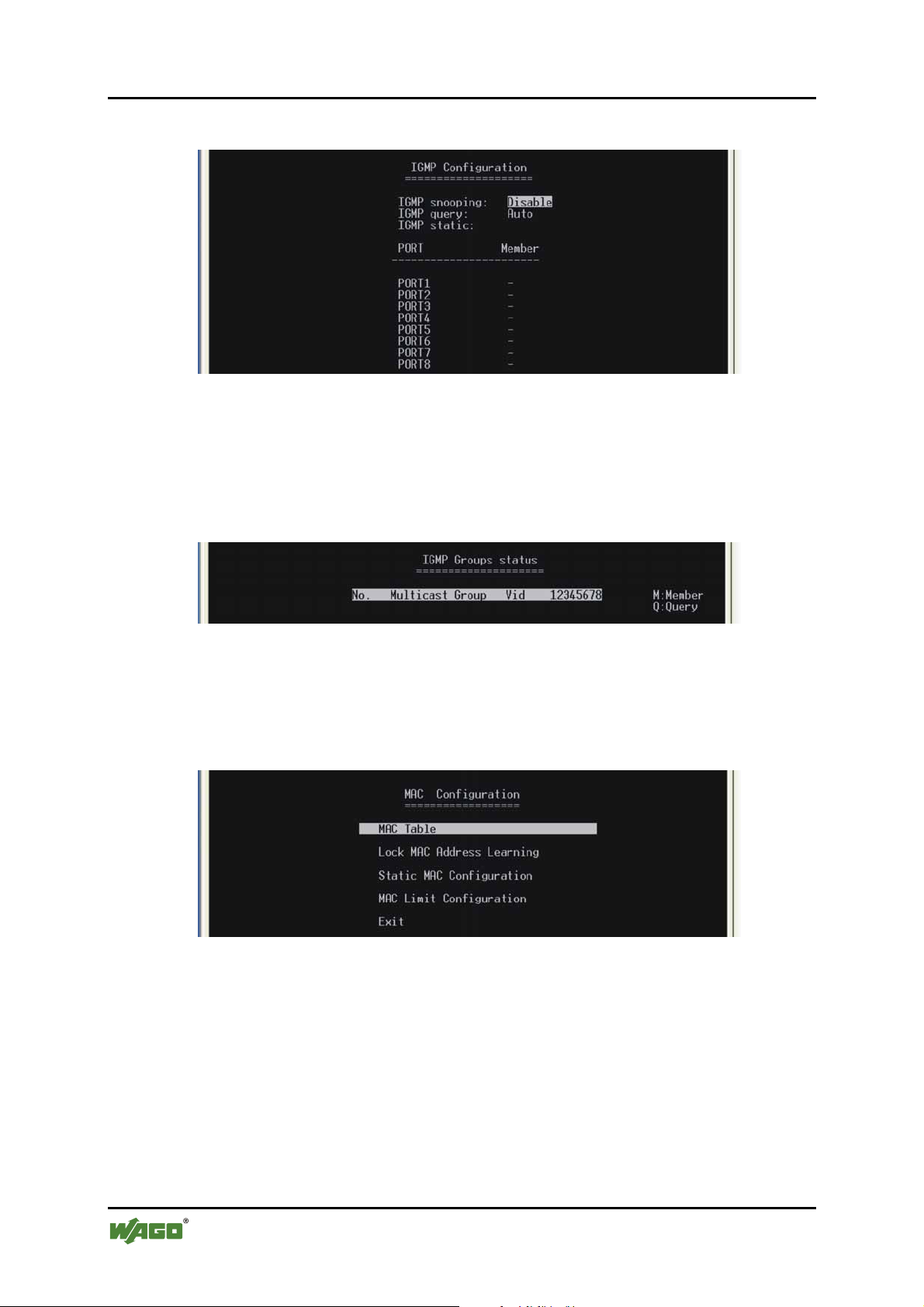
62 Configuration WAGO ETHERNET Accessories 852
852-104 7-Port 100BASE-TX + 2-Slot 100BASE-FX Industrial Managed Switch
SS19 – (DCM)/IGMP Configuration
Figure 41: IGMP Configuration
Select between IGMP Snooping (Disable/Enable), IGMP Query (Auto, Enable,
Disable) and IGMP static per port (Y/_).
SS20 – IGMP Groups Status
Figure 42: IGMP Groups status
View status of IGMP groups (only accessible if Snooping is enabled).
SS21 – (DCM)/MAC Configuration
Figure 43: MAC Configuration
Select field to configure.
Manual
Version 1.1.3
Page 63
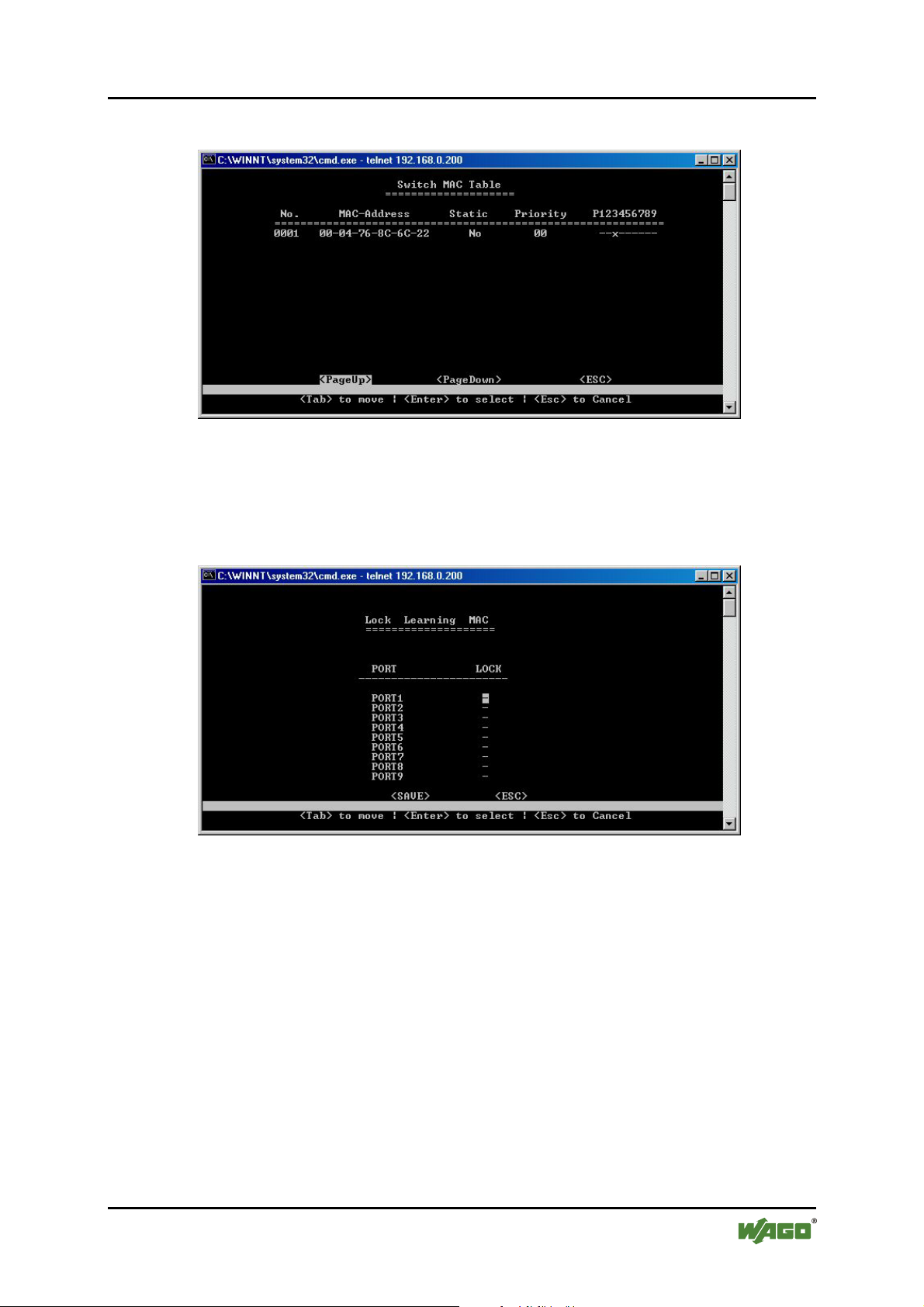
WAGO ETHERNET Accessories 852 Configuration 63
852-104 7-Port 100BASE-TX + 2-Slot 100BASE-FX Industrial Managed Switch
SS22 – MAC Table
Figure 44: MAC Table
View MAC address information.
Lock MAC Address Learning
Figure 45: Lock MAC Address Learning
Select if you want to put this lock on a port (choose Y/_ per port).
Manual
Version 1.1.3
Page 64
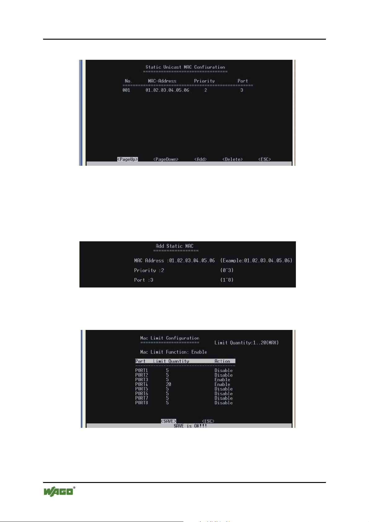
64 Configuration WAGO ETHERNET Accessories 852
852-104 7-Port 100BASE-TX + 2-Slot 100BASE-FX Industrial Managed Switch
SS23 – Static MAC Configuration
Figure 46: Static MAC Configuration
SS24 – Add Static MAC
(Appears when you select Add in previous window.) When cursor is on [ESC],
pressing [Enter] will give extra options: Add/SC – press [Tab] key twice to get
[ESC].
Figure 47: Add Static MAC
SS25 – MAC Limit Configuration
Figure 48: MAC Limit Configuration
Manual
Version 1.1.3
Page 65
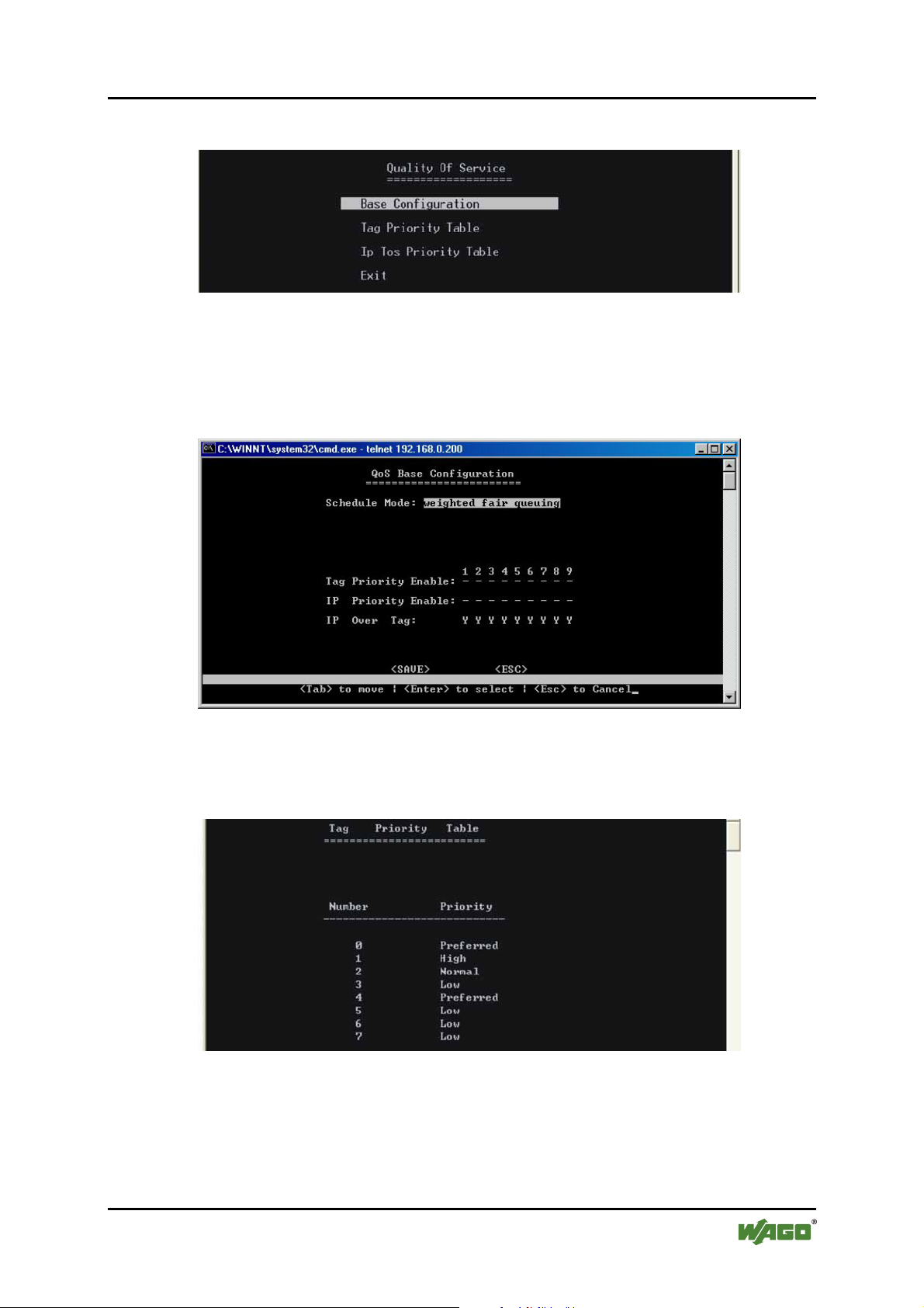
WAGO ETHERNET Accessories 852 Configuration 65
852-104 7-Port 100BASE-TX + 2-Slot 100BASE-FX Industrial Managed Switch
SS26 – (DCM)/Quality of Service
Figure 49: Quality of Service
SS27 – QoS Base Config.
(weighted fair queuing OR all high before low)
Figure 50: QoS Base Configuration
SS28 – (DCM)/QOS/Tag Priority Table
Figure 51: QoS Tag Priority Table
Manual
Version 1.1.3
Page 66
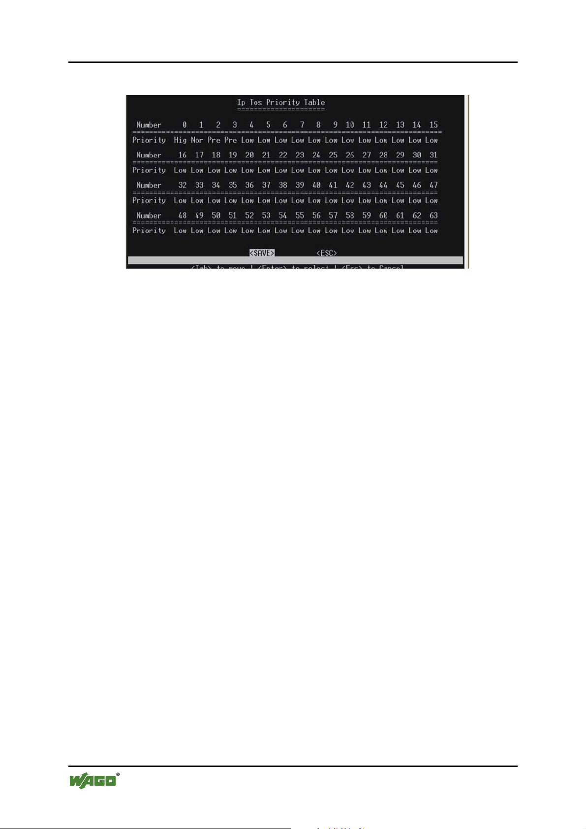
66 Configuration WAGO ETHERNET Accessories 852
852-104 7-Port 100BASE-TX + 2-Slot 100BASE-FX Industrial Managed Switch
SS29 IP ToS Priority Table
Figure 52: ToS Priority Table
Pos: 25.8.12 /Dokumentation allgemein/Glieder ungs elemente/---Seitenwechsel--- @ 3\mod_1221108045078_0.doc @ 21810 @ @ 1
Manual
Version 1.1.3
Page 67
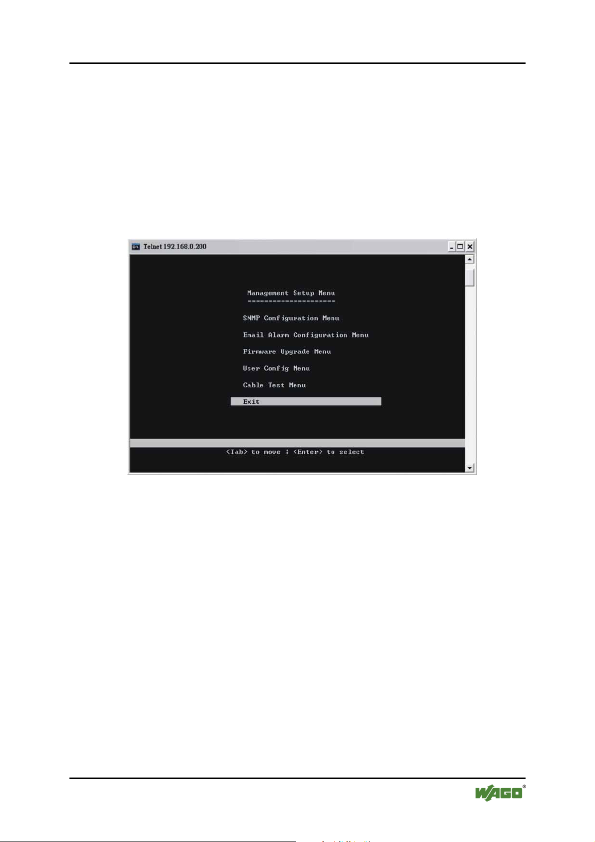
WAGO ETHERNET Accessories 852 Configuration 67
852-104 7-Port 100BASE-TX + 2-Slot 100BASE-FX Industrial Managed Switch
Pos: 25.8.13 /Serie 852 (Ethernet-Zubehör)/Konfi guration/B - Telnet/Managementkonfiguration1 @ 3\ mod_1222870998687_21.doc @ 23031 @ 3 @ 1
8.3.6 Management Setup Menu (MSM)
After logging into the system, you can use this menu to configure the settings for
remote access via SNMP agent and to configure the e-mail alarm or to upgrade
the firmware. The user should set the community string that controls access to the
onboard SNMP agent via in-band management software (SNMP Configuration).
The items provided by the Management Setup Menu are described in the
following sections.
SS30 – Management Setup Menu (MSM)
Figure 53: Management Setup Menu
Use the [Tab] key to move from one field to the next and the [Enter] key to
select.
(MSM)/SNMP Configuration Menu
Use the SNMP Configuration screen to display and modify parameters for the
Simple Network Management Protocol (SNMP). The Switch features an onboard
SNMP agent that monitors the status of its hardware as well as the traffic passing
through its ports. A computer attached to the network, called a Network
Management Station (NMS), can be used to access this information. Community
strings control access rights to the agent module. To communicate with the
switch, the NMS must first submit a valid community string for authentication.
The options for configuring community strings and related trap functions are
described in the following figures and tables.
Manual
Version 1.1.3
Page 68
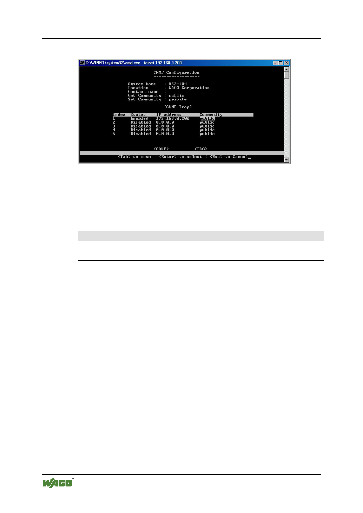
68 Configuration WAGO ETHERNET Accessories 852
852-104 7-Port 100BASE-TX + 2-Slot 100BASE-FX Industrial Managed Switch
SS31 – (MSM)/SNMP Configurations
Figure 54: SNMP Configuration
Use the [Tab] and [Enter] keys as previously. Enter the IP addresses of
computers that will be notified when abnormalities on a connection occur and an
alarm needs to be sent. Enter their community names and disable or enable their
alarm function.
Table 21: SNMP Configuration
Parameter Description
Index
Status
IP Address
Number assigned to each trap
Disable or enable the alarm function
Enter the IP addresses of computers that will be notified
when abnormalities on a connection occur and an alarm
needs to be sent. Enter their community names and disable
or enable their alarm function.
Community
Enter their community names
You can use an external SNMP-based application to configure and manage the
Switch. This management method requires the SNMP agent on the Switch and the
SNMP Network Management Station to use the same community string. This
management method, in fact, uses two community strings: the GET community
string and the SET community string. If the SNMP Network Management Station
only knows the SET community string, it can read and write to the MIBs.
However, if it only knows the GET community string, it can only read MIBs. The
default GET and SET community string for the Switch is “public”.
Manual
Version 1.1.3
Page 69
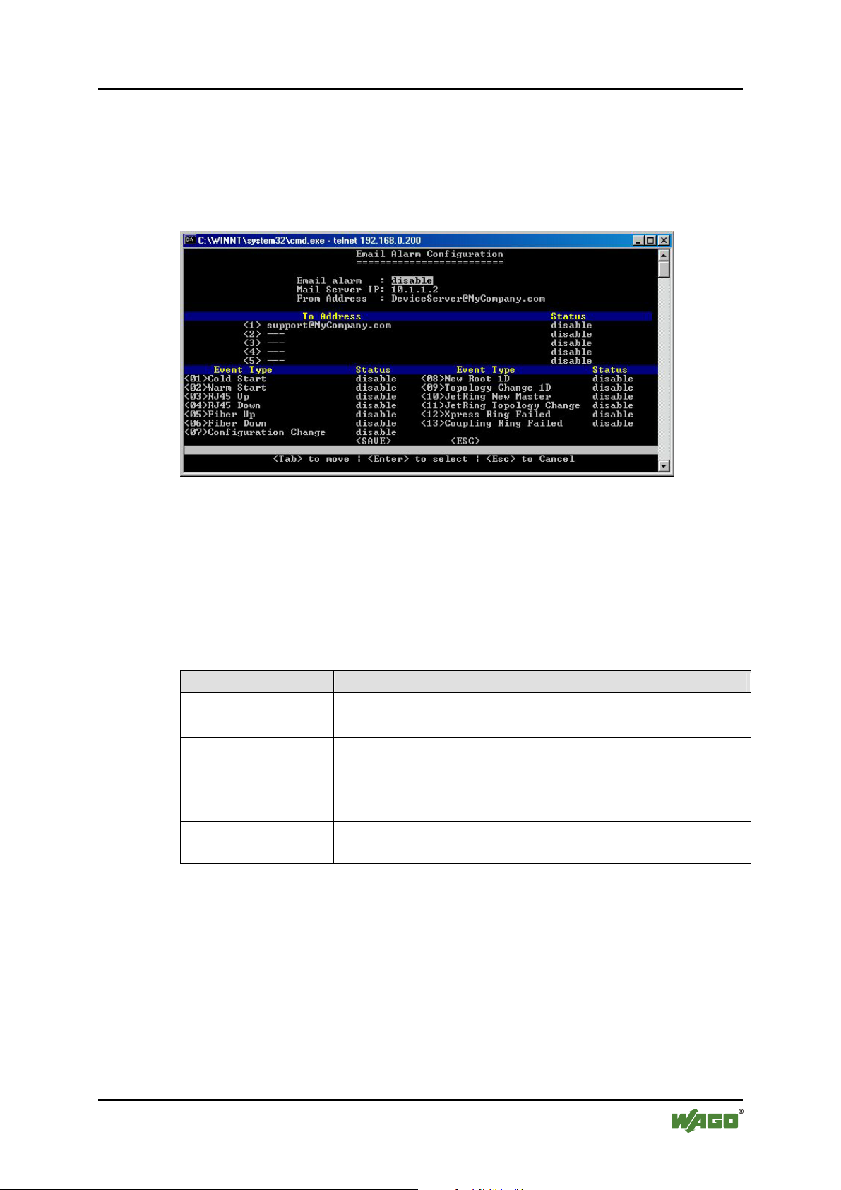
WAGO ETHERNET Accessories 852 Configuration 69
852-104 7-Port 100BASE-TX + 2-Slot 100BASE-FX Industrial Managed Switch
SS32 – (MSM)/E-mail Alarm Configuration
The Industrial Managed Switch instantaneously issues e mail warnings to
engineers when an exception occurs. Users can also connect a relay output to the
Switch’s terminal block to enable an acoustic alarm e.g. (please see hardware
configurations for detail).
Figure 55: eMail Alarm Configuration
Use the [Tab] and [Enter] keys as previously. The user must Enable the E-mail
Alarm function and provide the valid IP address of the mail server, which the
Switch will use and a valid e-mail address for the Switch. The user can select up
to five (5) e-mail addresses that error messages will be e mailed to. Provide the
valid address and “Enable” the status. The user must then select which exceptions
will trigger an e-mail alert.
Table 22: eMail Alarm Configuration
Parameter Description
E-mail Alarm
Mail Server IP
From Address
Enable/Disable
Provide valid IP address of Mail Server
Assign an e-mail address to the Switch (E.g. Industrial
Managed Switch@xxxxxx)
To Address
Provide the e-mail address(es) to which e-mail alarms
should be sent. Remember to enable their statuses.
Event Type
Enable the events for which you want to receive an e-mail
alert.
Manual
Version 1.1.3
Page 70
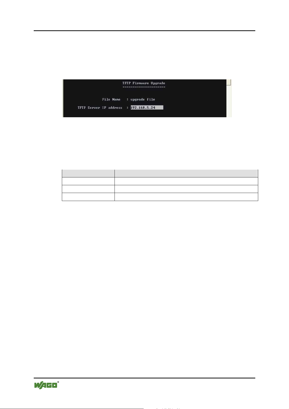
70 Configuration WAGO ETHERNET Accessories 852
852-104 7-Port 100BASE-TX + 2-Slot 100BASE-FX Industrial Managed Switch
SS33 – (MSM)/Firmware Upgrade Menu
The firmware for the Industrial Managed Switch can also be upgraded via TFTP if
such a file has been prepared. Create a TFTP server and upload into it the new
firmware file that will be downloaded. This feature helps users to keep updating
the firmware with new/enhanced features. For example:
Figure 56: Firmware Upgrade
Use the [Tab] to move up and down the menu, and the [Enter] key to select and
unselect, or [ESC] to cancel.
Choose the following operations from the menu system:
Table 23: Firmware Upgrade
Parameter Description
File Name
IP address
Start Upgrade
Enter a file name for new firmware
Enter IP address of a TFTP server.
Select to upgrade firmware
The Industrial Managed Switch will download the file and restart to affect the
new settings.
Manual
Version 1.1.3
Page 71
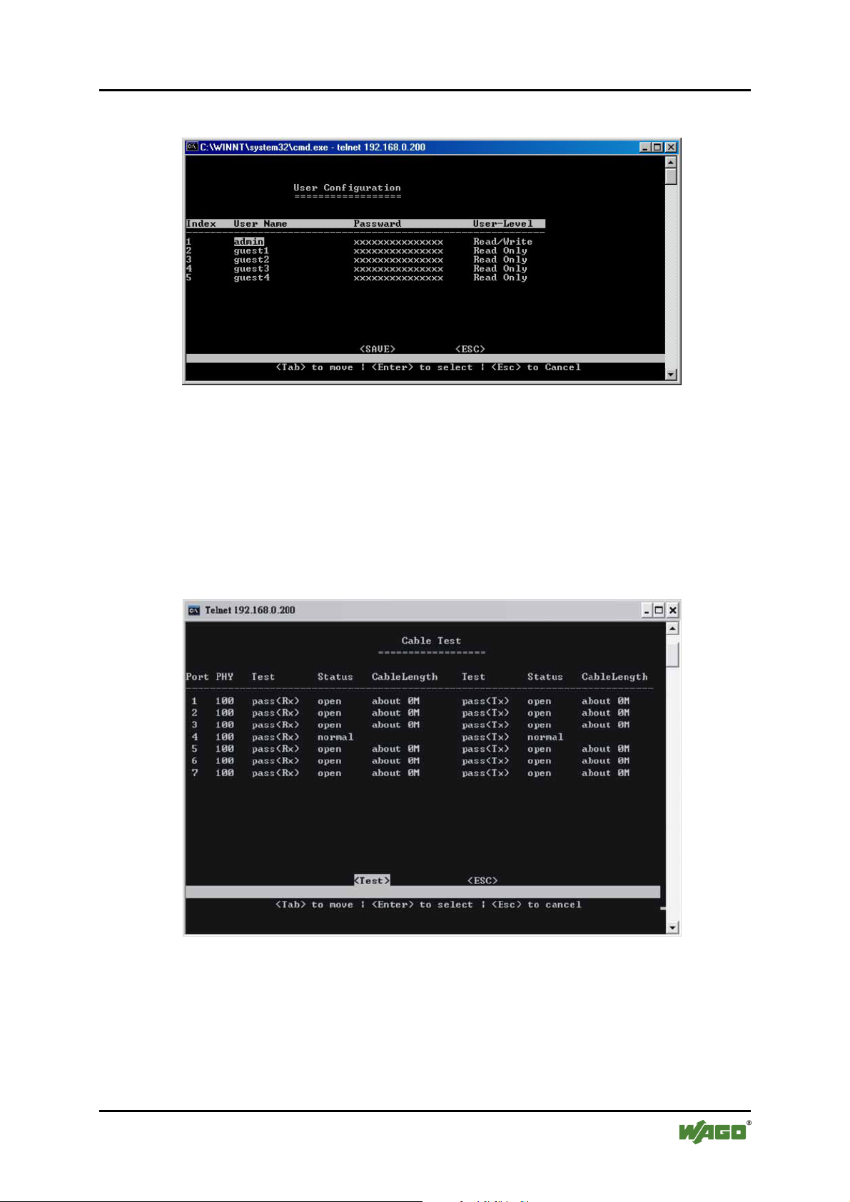
WAGO ETHERNET Accessories 852 Configuration 71
852-104 7-Port 100BASE-TX + 2-Slot 100BASE-FX Industrial Managed Switch
SS34 – (MSM)/User Configuration Menu
Figure 57: User Configuration
SS35 – (MSM)Cable Test Menu
Cable Test is used to diagnose the physical copper links connected each port, by
separate pairs in a cable. If the link is well connected, the Status column will show
“normal”. If the link is disconnected, the Status column will show “open”, and
the Cable Length column will display the estimated distance from the port to the
location where the circuit is open.
Figure 58: Cable Test Menu
Manual
Version 1.1.3
Page 72
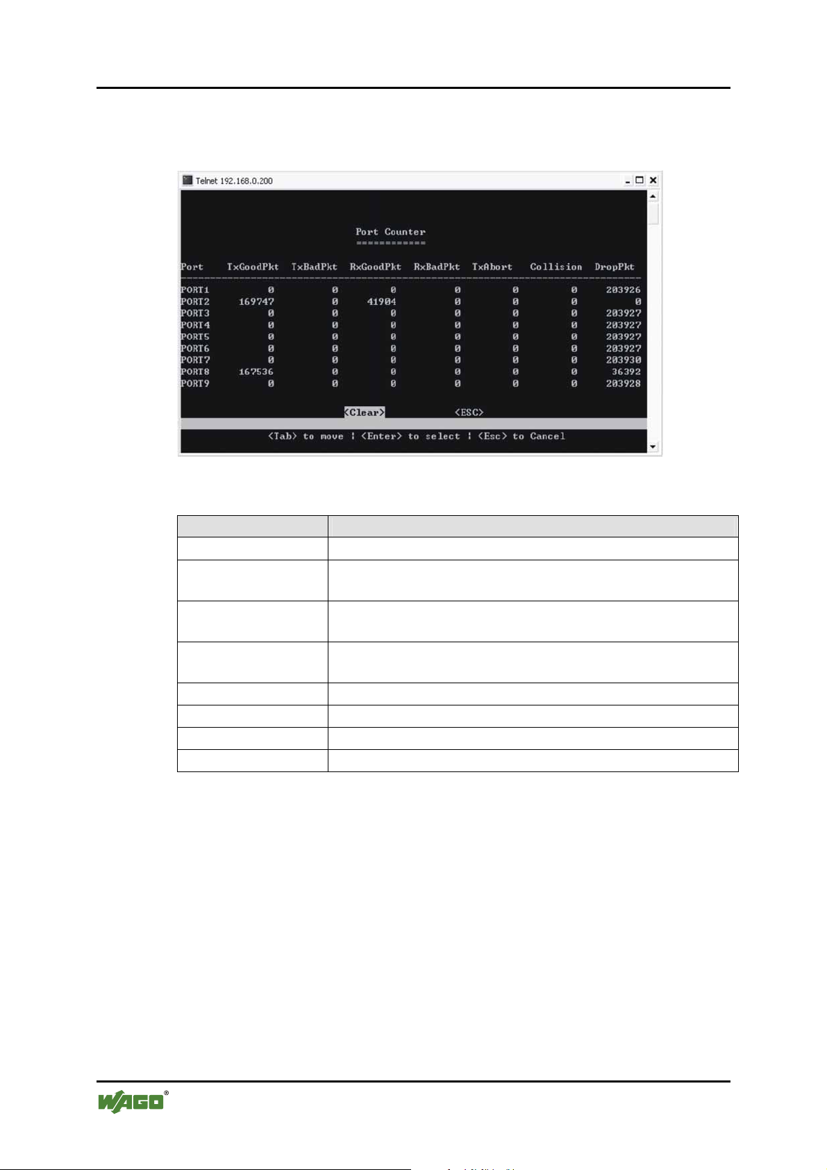
72 Configuration WAGO ETHERNET Accessories 852
852-104 7-Port 100BASE-TX + 2-Slot 100BASE-FX Industrial Managed Switch
SS36 – Main Menu/Port Counter Menu
The user can view the port’s statistics from this screen.
Figure 59: Port Counter
Table 24: Port Counter
Parameter Description
Port
TxGoodPkt
Port Number
Good packets transmitted by the port
TxBadPkt
Bad packets transmitted by the port
RxGoodPkt
Good packets received by the port
RxBadPkt
TxAbort
Collision
DropPkt
Bad packets received by the port
Transmission aborted by/from the port
Packet collision information
Number of packets dropped by the port
Manual
Version 1.1.3
Page 73
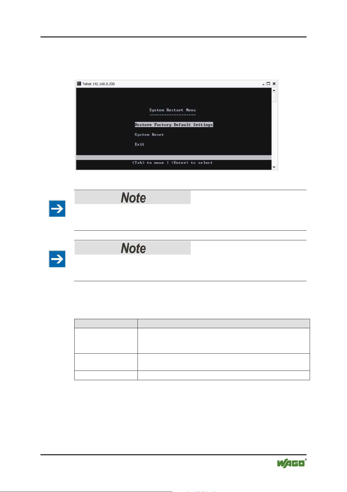
WAGO ETHERNET Accessories 852 Configuration 73
852-104 7-Port 100BASE-TX + 2-Slot 100BASE-FX Industrial Managed Switch
SS37 – Main Menu/System Restart Menu
Users can remotely restart the Switch or reset the Switch to factory default
settings via software without turning OFF the power.
Figure 60: System Restart Menu
Please note
If you highlight either „Restore Factory Settings“ or „System Reset“ and press
[Enter], the reset will commence immediately!
Pos: 25.9 /Dokumentation allgemein/Gliederungse lemente/---Seitenwechsel--- @ 3\mod_1221108045078_0.doc @ 21810 @ @ 1
Please note
If you press [Enter] when on the “Restore” field will set the switch back to
factory defaults immediately, all saved configurations will be lost!
Use the [Tab] to move up and down the menu, and the [Enter] key to select.
Choose the following operations from the menu system:
Table 25: System Restart Menu
Parameter Description
System Restore
Factory Default
Pressing [Enter] when on the Restore field will set the
switch back to factory defaults IMMEDIATELY.
Settings
System Reset
Press [Enter] when on the “Reset” field to reboot the
switch. After rebooting, it is necessary to log in again
Exit
Exits menu and returns to Main Menu
Manual
Version 1.1.3
Page 74
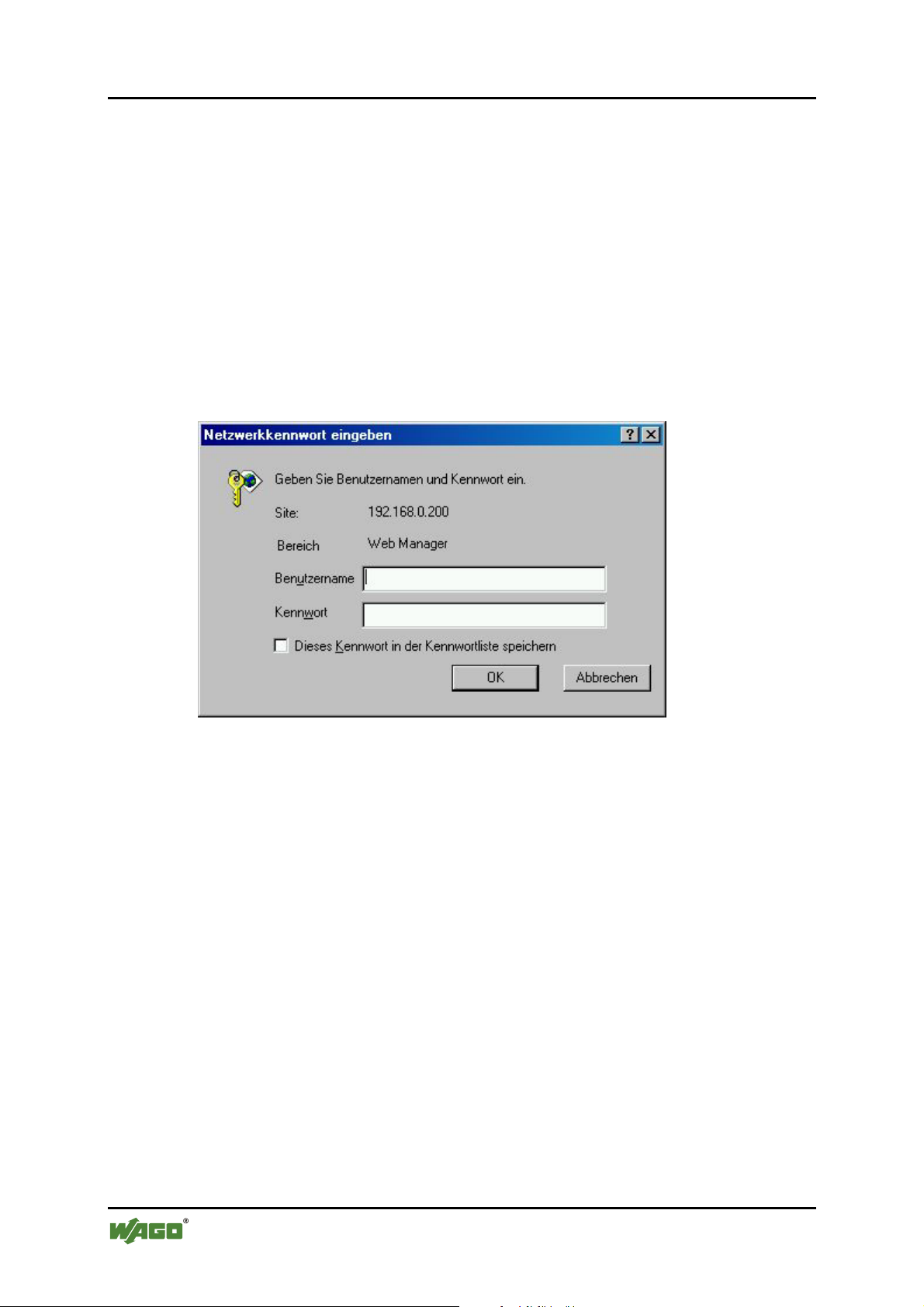
74 Configuration WAGO ETHERNET Accessories 852
852-104 7-Port 100BASE-TX + 2-Slot 100BASE-FX Industrial Managed Switch
Pos: 25.10.1 /Serie 852 (Ethernet-Zubehör)/Konfi guration/C - Internetbrowser/Interface Inter netbrowser @ 3\mod_1222862507015_21.doc @ 22918 @ 2 @ 1
8.4 C – Using the Internet Browser Interface
Pos: 25.10.2 /Serie 852 (Ethernet-Zubehör)/Konfi guration/C - Internetbrowser/Überblick @ 3\mod_1222 867190250_21.doc @ 22947 @ 3 @ 1
8.4.1 Overview
This section gives a step-by-step guide to configuring the Industrial Managed
Switch’s management functions. A series of screen shots (SS#) and instructions
illustrate the main menu structure and how it works.
Firstly, open a web browser and key in the Switch’s IP address – then press
[Enter]. A Web Manager page like this will pop up on your screen:
SS1 – Log in
Pos: 25.10.3 /Dokumentation allgemein/Glieder ungs elemente/---Seitenwechsel--- @ 3\mod_1221108045078_0.doc @ 21810 @ @ 1
Figure 61: Log-in
The default username is: admin
There is no preset password for this module, so click on [OK] to proceed.
Manual
Version 1.1.3
Page 75
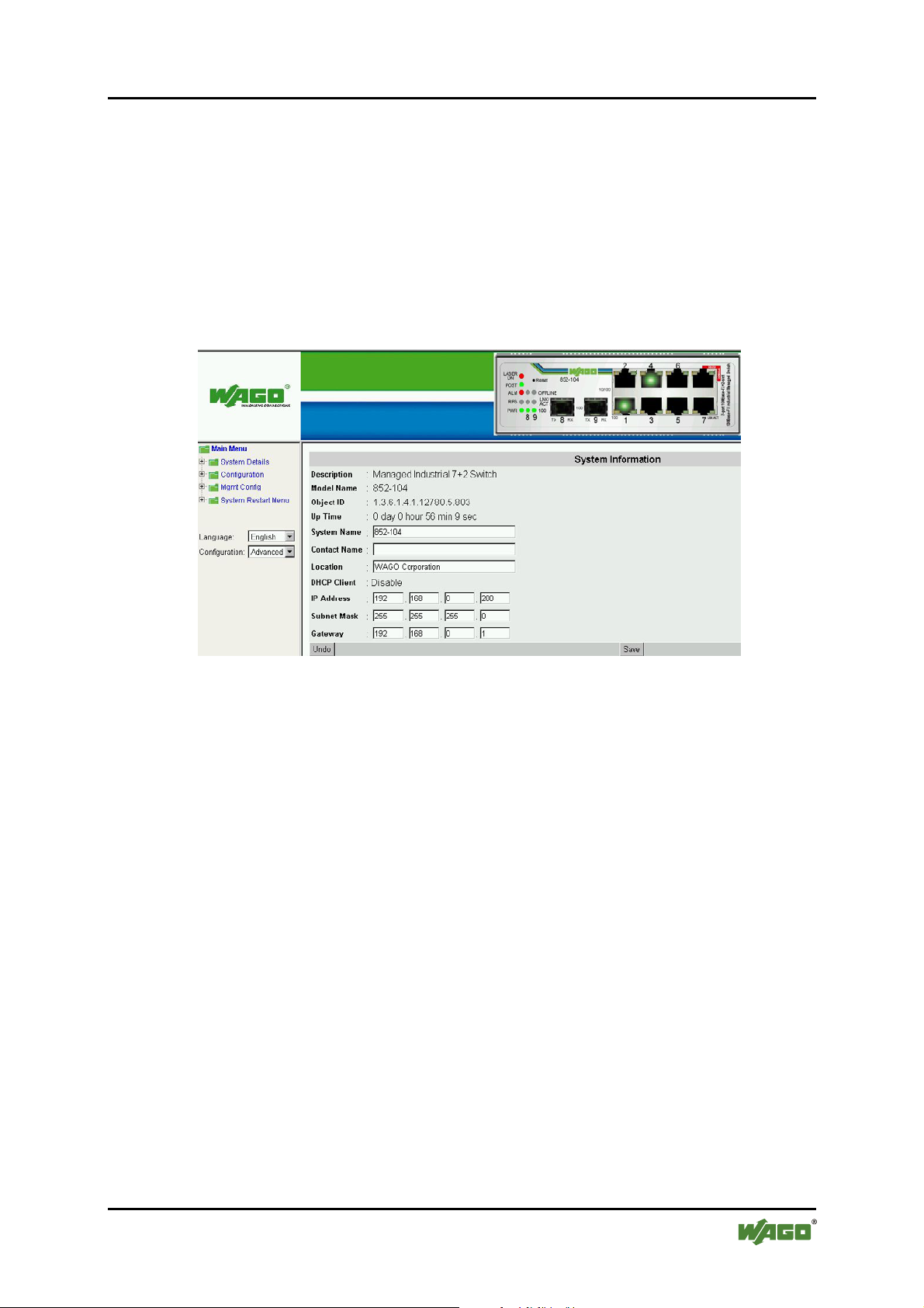
WAGO ETHERNET Accessories 852 Configuration 75
852-104 7-Port 100BASE-TX + 2-Slot 100BASE-FX Industrial Managed Switch
Pos: 25.10.4 /Serie 852 (Ethernet-Zubehör)/Konfi guration/C - Internetbrowser/Systemdetails @ 3\ mod _122 2866938703_21.doc @ 22944 @ 3 @ 1
8.4.2 System Details
When your Web browser connects with the Industrial Managed Switch’s Web
agent, the home page is displayed as shown below. The home page displays the
Main Menu on the left side of the screen and System Information as the main
page. The Main Menu links are used to navigate to other menus and display
configuration parameters and statistics.
SS2 – Homepage (System Detail/System Info)
Figure 62: Homepage
Click on each parameter field to modify the specific settings, click [Undo] to
restore previously saved configurations or click [Save] to retain newly entered
information. See description below:
Manual
Version 1.1.3
Page 76
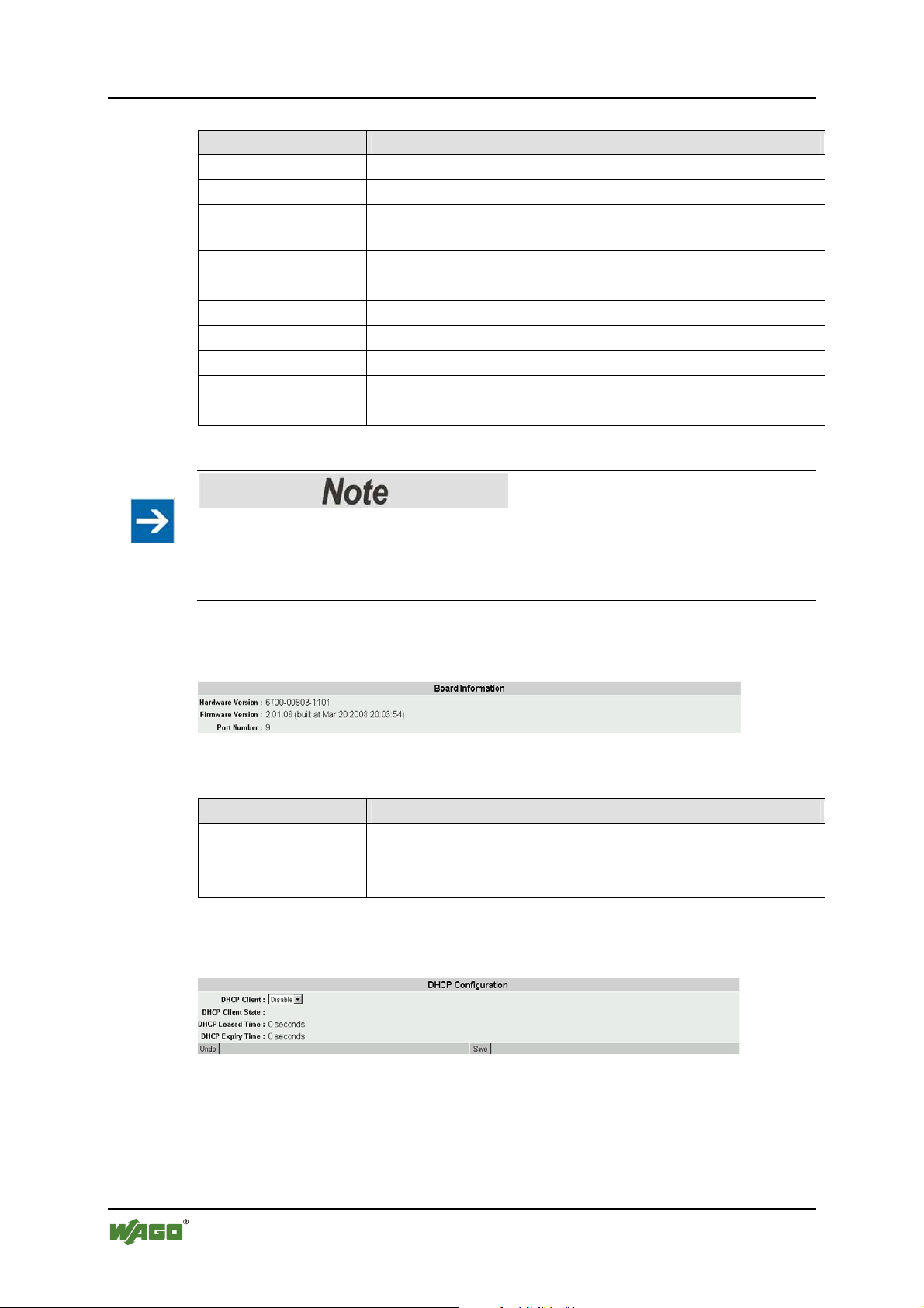
76 Configuration WAGO ETHERNET Accessories 852
852-104 7-Port 100BASE-TX + 2-Slot 100BASE-FX Industrial Managed Switch
Table 26: Homepage
Parameter Description
Description
Object ID
Up Time
Provides description of the Switch
ID or Serial number
Provides information on up time, or the time that the system
has been operating
System Name
Contact
Location
DHCP Client
IP Address
Subnet Mask
Gateway
Modify the name of the Switch here
Enter a contact name
Enter the location of Switch
Disabled or client’s name
Default: 192.168.100.1
Default: 255.255.0.0
Default: 192.168.0.1
Please note
The above are factory defaults used as an example only. A new address is
important. Choose numbers between 0 and 254 in each sub-address field. Make a
note of them and keep the details in a safe place.
Pos: 25.10.5 /Dokumentation allgemein/Glieder ungs elemente/---Seitenwechsel--- @ 3\mod_1221108045078_0.doc @ 21810 @ @ 1
SS3 – Board Info
Figure 63: Board Information
Table 27: Board Information
Parameter Description
Hardware Version
Firmware Version
Port Number
Provides information on the hardware version
Provides information on the firmware version
Provides information on the number of ports available
SS4 – DHCP Configuration
Figure 64: DHCP Configuration
Manual
Version 1.1.3
Page 77
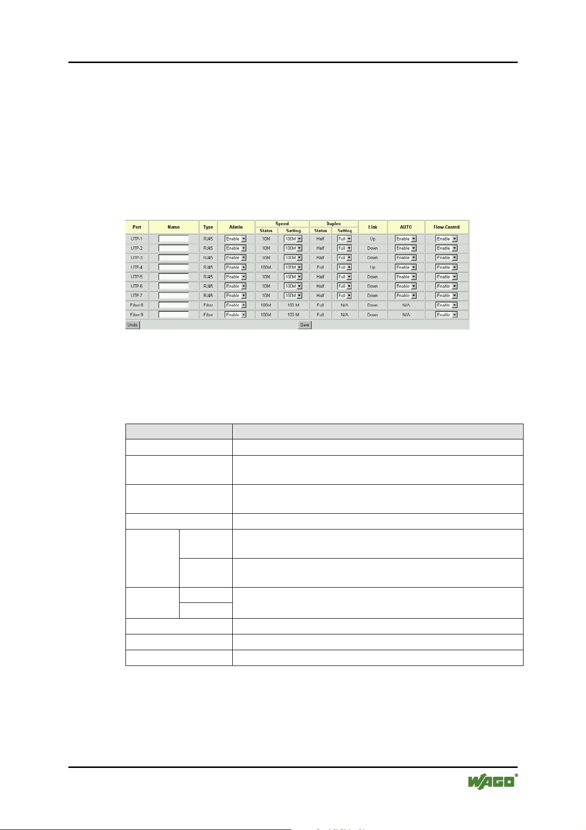
WAGO ETHERNET Accessories 852 Configuration 77
852-104 7-Port 100BASE-TX + 2-Slot 100BASE-FX Industrial Managed Switch
Pos: 25.10.6 /Serie 852 (Ethernet-Zubehör)/Konfi guration/C - Internetbrowser/Konfiguration @ 3\mo d_1 222863227546_21.doc @ 22921 @ 3 @ 1
8.4.3 Configuration
Port Configuration
This section allows you to view and change the parameter settings for the
individual ports on the Industrial Managed Switch. See screen shot and table
below for adjustable parameters.
SS5 – Config./Port Configuration
Figure 65: Port Configuration / Advanced Control
Click on each parameter field to modify the desired setting, then click on [Undo]
to restore previously saved configurations or click on [Save] to retain newly
entered information. See description below:
Table 28: Port Configuration
Parameter Description
Port
Name
Port types and numbers.
Assign a names to each port to keep record of your
connections.
Type
Type of connector for each port (auto-detects fiber and
RJ-45).
Admin
Speed
Status
Enable or disable admin configurations.
Provides information on speed at which ports are currently
operating.
Setting
Set speed for RJ-45 ports. (The speed for fiber ports is
fixed).
Status Duplex
Setting
Link
AUTO
Flow Control
Provides information on Duplex Status.
Select half /full duplex modes.
Provides information on link status.
Enable/Disable Auto negotiation on copper ports.
Enable/Disable flow control for each port.
Manual
Version 1.1.3
Page 78
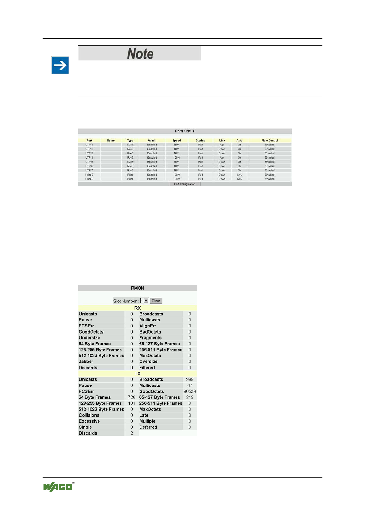
78 Configuration WAGO ETHERNET Accessories 852
852-104 7-Port 100BASE-TX + 2-Slot 100BASE-FX Industrial Managed Switch
Please note
Disable the auto (auto negotiation) function to configure speed and duplex. Click
on [Undo] to restore previously saved configurations or click on [Save] to retain
newly entered information.
SS6 - Port Status
Figure 66: Port Status
This window offers at-a-glance status reporting for Switch operations. Click on
the Port Configurations button to return to the Port Configurations window if you
need to change a setting.
SS7 – RMON Status
The user can view the details of packet transmission and reception at each port.
Select the port number (1 … 9) to see the port details.
Figure 67: RMON Status
Pos: 25.10.7 /Dokumentation allgemein/Glieder ungs elemente/---Seitenwechsel--- @ 3\mod_1221108045078_0.doc @ 21810 @ @ 1
Manual
Version 1.1.3
Page 79
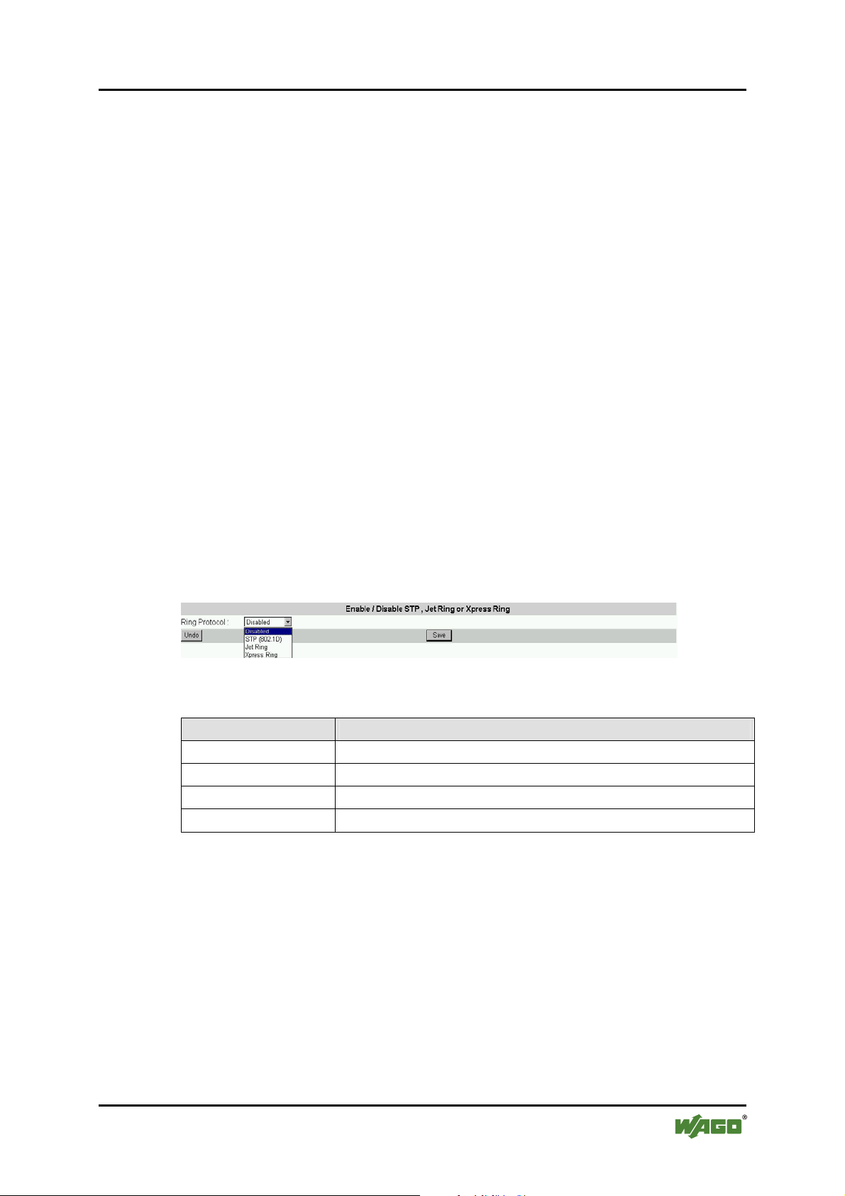
WAGO ETHERNET Accessories 852 Configuration 79
852-104 7-Port 100BASE-TX + 2-Slot 100BASE-FX Industrial Managed Switch
Pos: 25.10.8 /Serie 852 (Ethernet-Zubehör)/Konfi guration/C - Internetbrowser/Bridge Menu @ 3\mod_1222 8609 17203_21.doc @ 22909 @ 3 @ 1
8.4.4 Bridge Menu
Using the Bridge Menu
The Bridge menu is used for configuring the Jet Ring, Spanning Tree Algorithm
and Xpress Ring settings, as well as the traffic class priority threshold and the
address aging time.
The Jet Ring offers fast recovery time of less than 300 ms in case of link failure
(if Jet Ring is enabled). It has a longer recovery time than Xpress Ring (50 ms),
but it needs almost no set-up configuration.
Xpress Ring offers a very fast link-failure recovery time of 50 ms, but the user
must select the role of the Switch (arbiter or forward) and which two ports will be
part of the Xpress Ring network.
The Spanning Tree Algorithm is used for detecting and disabling network loops,
and to provide backup links between switches, bridges or routers. This allows the
switch to communicate and interact with other bridging devices (i.e. STAcompliant devices) in a network to ensure that only one route exists between any
two stations, and it provides redundant or backup links that automatically take
over when a primary link goes down.
SS8 - Bridge Configuration
Figure 68: Bridge Configuration
Table 29: Bridge Configuration
Parameter Description
Disabled
STP (802.1D)
Jet Ring
Xpress Ring
Disable redundancy function
Redundant link via Spanning Tree Protocol
Redundant link with fast recovery time of less than 300 ms
Redundant link with fastest recovery time: less than 50 ms
Select the appropriate mode as per the network needs, then click on [Save] to
retain newly entered information or click on [Undo] to restore previously saved
configurations.
Manual
Version 1.1.3
Page 80
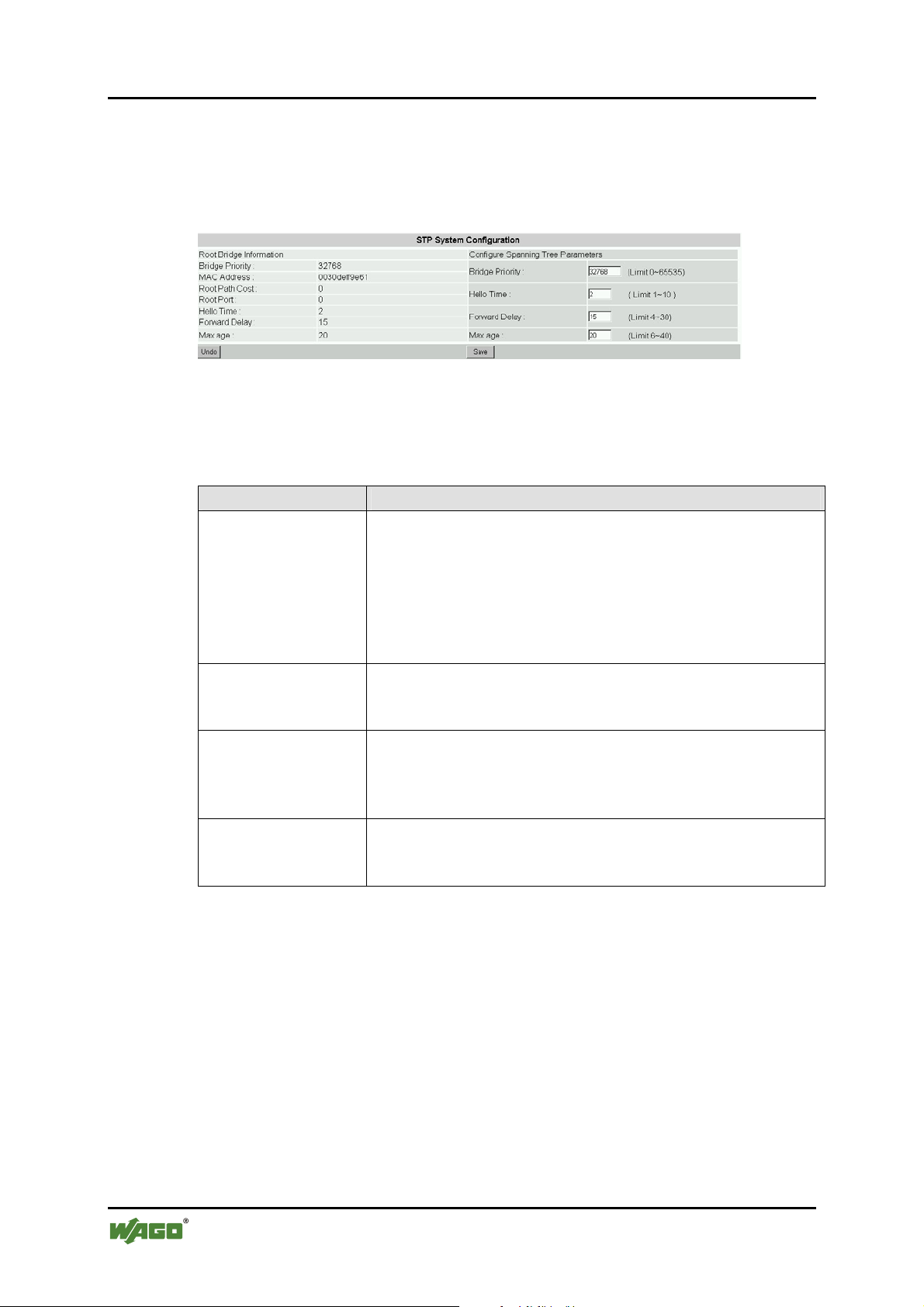
80 Configuration WAGO ETHERNET Accessories 852
852-104 7-Port 100BASE-TX + 2-Slot 100BASE-FX Industrial Managed Switch
SS9 – (Bridge)/STP System Configuration
This screen allows the user to enter the STP parameters for the Switch. Please
note: users must select “STP 802.1D” under Bridge Configuration to perform
this configuration. Otherwise, this option will not be accessible.
Figure 69: STP System Configuration
Enter the appropriate entries, then click on [Save] to retain newly entered
information or click on [Undo] to restore previously saved configurations.
Table 30: STP System Configuration
Parameter Description
Bridge Priority
Set the bridge priority. The limit is given between 0 (the
highest priority) and 65535 (the lowest priority).
Bridge priority is used in selecting the root device, root
port, and designated port. The device with the highest
priority becomes the STA root device. However, if all
devices have the same priority, the device with the lowest
MAC address will then become the root device.
Hello Time
Time interval (in seconds) at which the root device
transmits a configuration message.
The limit given is from 1 … 10 s.
Forward Delay
Set Forward Delay. The limit given is from 4 … 30 s. This
is the maximum time (in seconds) the root device will wait
before changing states (i.e., listening to learning to
forwarding).
Max age
Set the (maximum age) waiting time for receiving packets
before attempting to reconfigure the link. The limit given is
from 6 … 40 s.
Manual
Version 1.1.3
Page 81
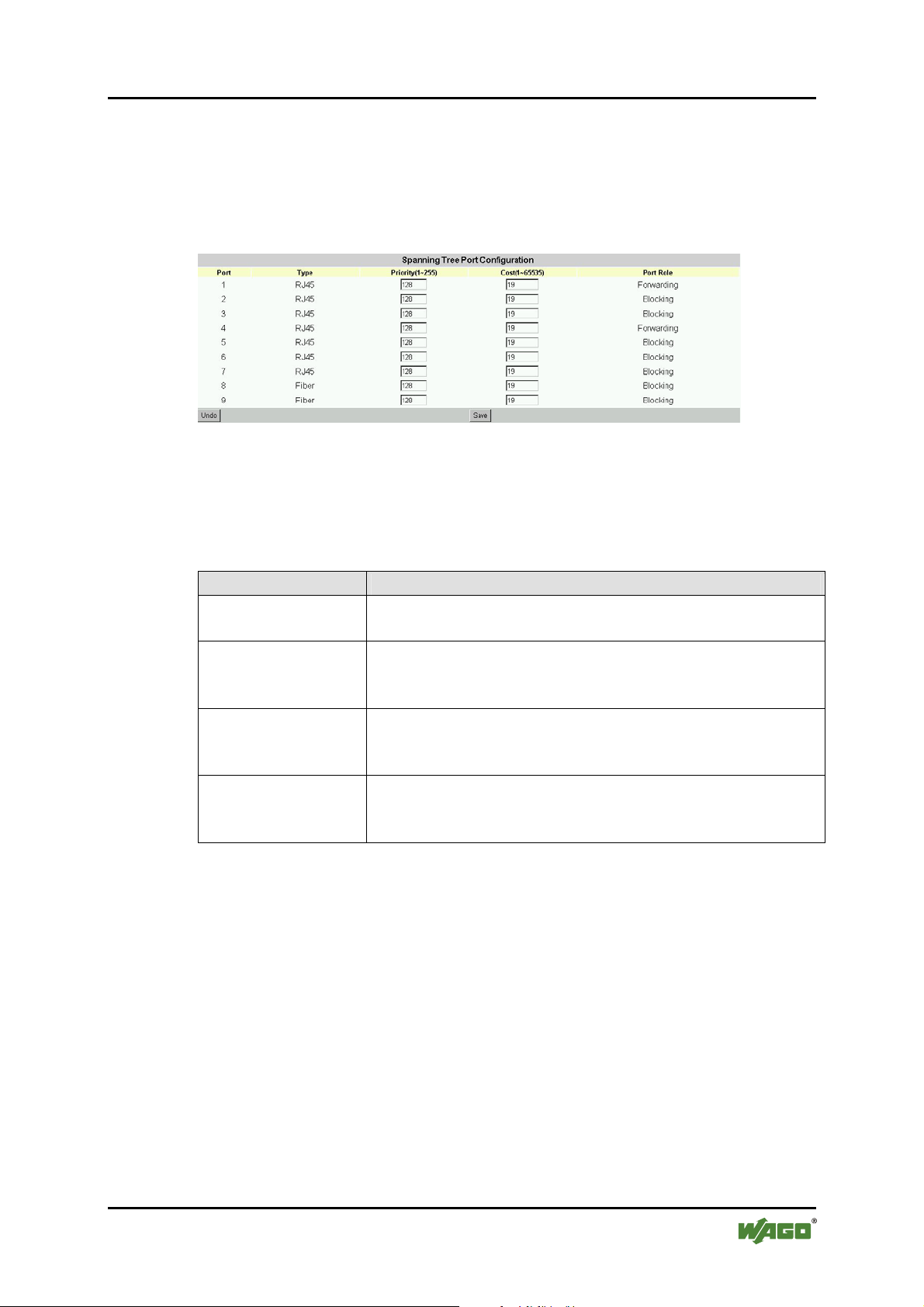
WAGO ETHERNET Accessories 852 Configuration 81
852-104 7-Port 100BASE-TX + 2-Slot 100BASE-FX Industrial Managed Switch
SS10 – (Bridge)/STP Per-Port Configuration
STP allows the Switch to assign a priority status to each of its ports, with respect
to other networking nodes in the network. In other words, STP determines the best
route for data to flow, given the priority level of each node on the network. Ensure
that this function is activated to avoid collisions and when setting up backup links.
Figure 70: Spanning Tree Po rt Configuration
Click on each parameter field to modify the desired setting, then click on [Undo]
to restore previously saved configurations or click on [Save] to retain newly
entered information. See description below:
Table 31: STP per Port Configuration
Parameter Description
Port Type
RJ-45: Ethernet port
Fiber: Fiber port
Port Priority
(1 … 255)
Set the priority of each port. The limit given is from
1 … 255. The lowest number means highest priority. The
default priority is set to 128 – the midpoint of this limit.
Cost ( 1 … 65535)
Set the cost assigned to each port. This will determine the
route of information flow. The higher the cost the less
suitable the port is to be a node for the STP.
Port Role
Blocking the port is blocking by Spanning Tree
Protocol
Forwarding the port is forwarding
Manual
Version 1.1.3
Page 82
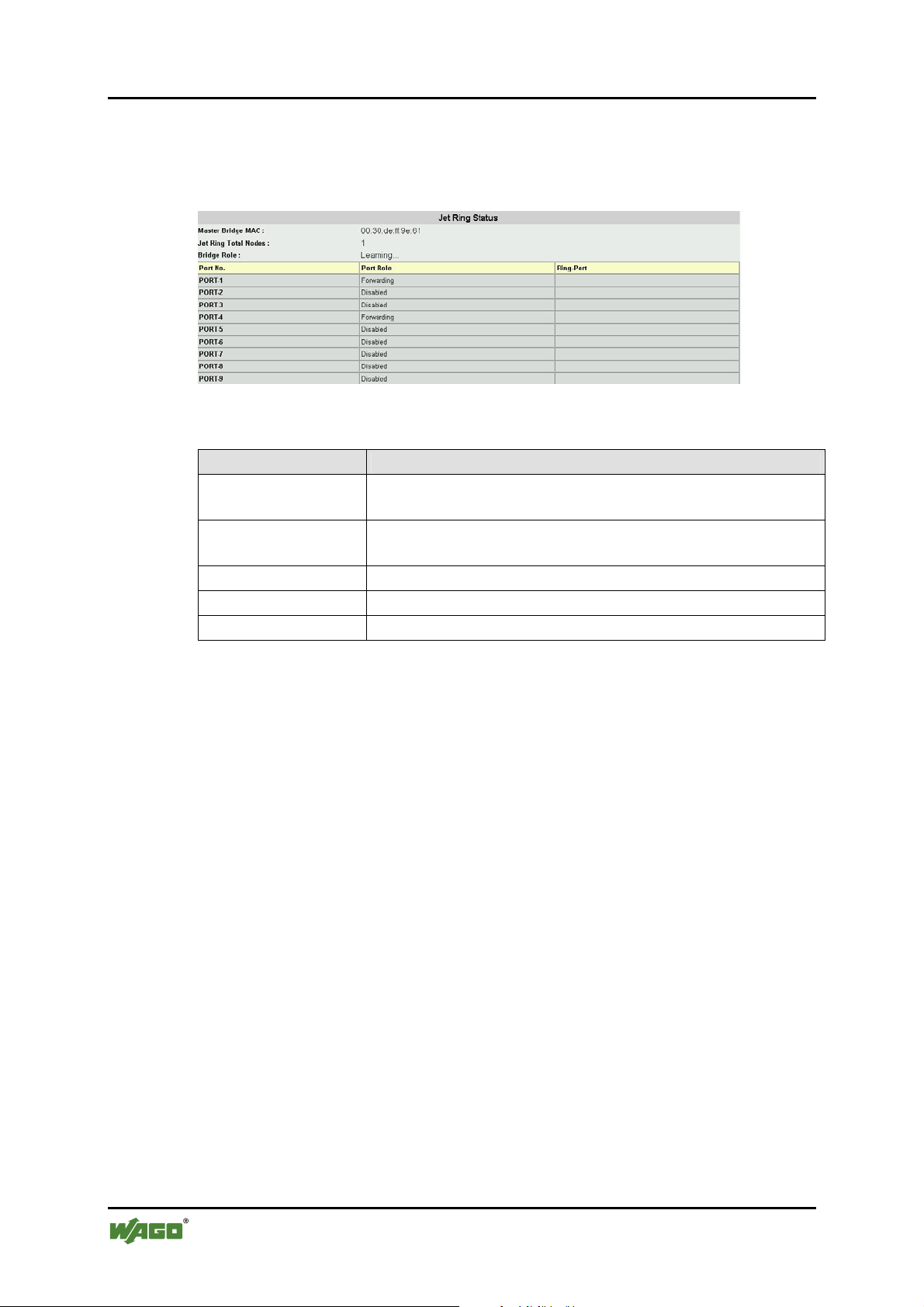
82 Configuration WAGO ETHERNET Accessories 852
852-104 7-Port 100BASE-TX + 2-Slot 100BASE-FX Industrial Managed Switch
SS11 – (Bridge)/Jet Ring Status
Users can view the Jet Ring status after enabling the Jet Ring at the menu Bridge
Configuration.
Figure 71: JetRing Status
Table 32: JetRing Status
Parameter Description
Master Bridge
Display MAC address of the Switch in the Jet Ring.
MAC
Jet Ring Total
Number of Switches forming a Jet Ring
Nodes
Bridge Role
Port Role
Ring Port
The role of the Switch
Display each port’s role
Display which ports are ring ports
Manual
Version 1.1.3
Page 83
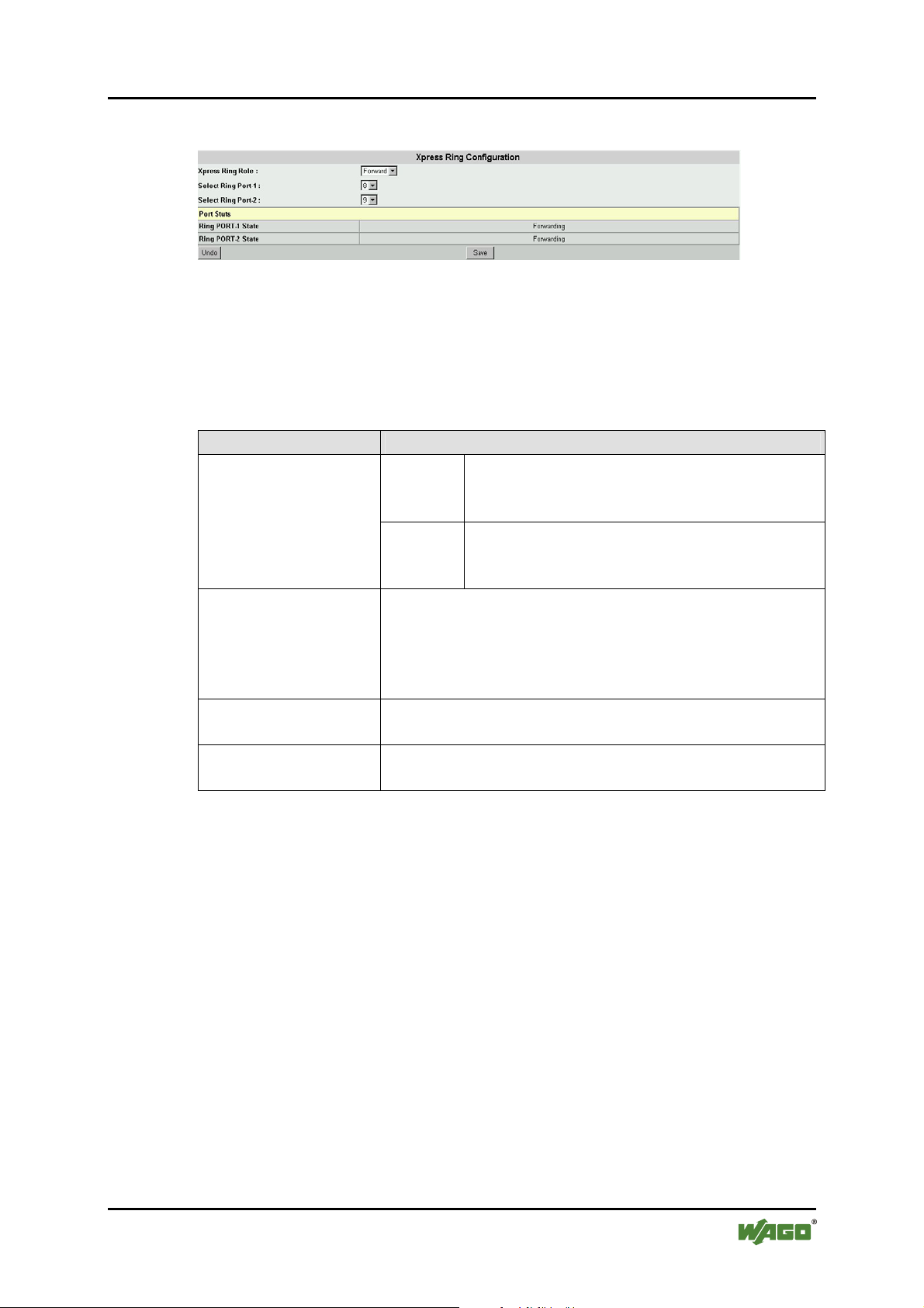
WAGO ETHERNET Accessories 852 Configuration 83
852-104 7-Port 100BASE-TX + 2-Slot 100BASE-FX Industrial Managed Switch
SS12 – (Bridge)/Xpress Ring Configuration
Figure 72: XpressRing Configuration
Here you must set the Switch’s role in the Xpress Ring network and the ports that
will be part of the Xpress Ring. If the network’s configuration changes (e.g. for a
node failure or added switch) the MIS personnel has to make sure these settings
are still valid – if the ring is set for XPress Ring.
Table 33: XpressRing Configuration
Port Configuration
Xpress Ring Role
Arbiter
The Switch which receives status reports
submitted from other Switches of the ring and
decides the ring recovery behaviours.
Forward
The Switch which is not the Arbiter of the ring
and will forward the received status reports on
the other side of ring ports.
Port status
Display the ring port statuses as:
- Forwarding for packet transmitting and
receiving status, or
- Blocking for port disabled or link down
status.
Select Ring Port-1
The first ring port with the link composing part of the
Xpress Ring.
Select Ring Port-2
The second port with the link composing part of the
Xpress Ring.
Pos: 25.10.9 /Dokumentation allgemein/Glieder ungs elemente/---Seitenwechsel--- @ 3\mod_1221108045078_0.doc @ 21810 @ @ 1
Manual
Version 1.1.3
Page 84
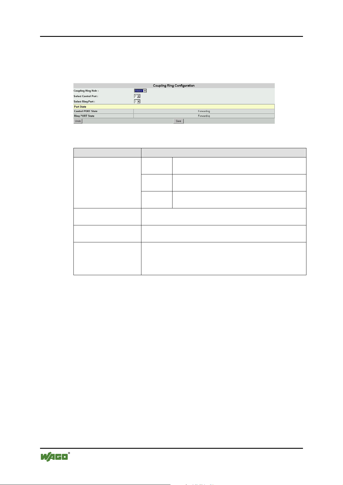
84 Configuration WAGO ETHERNET Accessories 852
852-104 7-Port 100BASE-TX + 2-Slot 100BASE-FX Industrial Managed Switch
Pos: 25.10.10 /Serie 852 (Ethernet-Zubehör)/Konf iguration/C - Internetbrowser/Coupling Ring Menu @ 3\mod_1 222861984109_21.doc @ 22912 @ 3 @ 1
8.4.5 Coupling Ring
Set Coupling Ring configurations to all Switches of either side of two
interconnected Xpress Rings.
Figure 73: CouplingRing Configuration
Table 34: XpressRing Configuration
Port Configuration
The Switch with the backup secondary link to
the peer Xpress Ring.
The Switch with the primary link to the peer
Xpress Ring.
The Switches not with the links connecting to
peer Xpress Ring.
Pos: 25.10.11 /Dokumentation allgemein/Gliederungselemente/---Seitenwechsel--- @ 3\mod_1221108045078_0.doc @ 21810 @ @ 1
Coupling Ring Role
Select Control Port
Select Ring Port
Port State
Arbiter
Master
Normal
The Control Port of Coupling Ring Master Switch or
Arbiter Switch for communication with each other.
The Ring Port of Coupling Ring Master Switch or Arbiter
Switch for connection to the peer coupled Xpress Ring.
Display the port status of Control Port or Ring Port as
- Forwarding for packet transmitting and
receiving status, or
- Blocking for port disabled or link down status
Manual
Version 1.1.3
Page 85
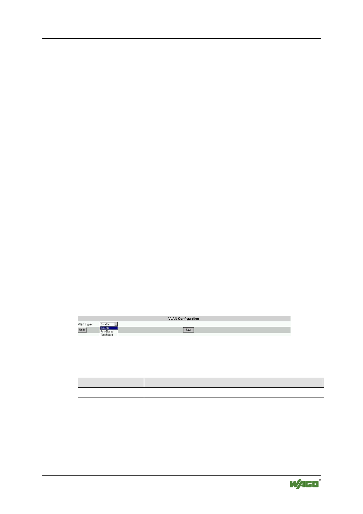
WAGO ETHERNET Accessories 852 Configuration 85
852-104 7-Port 100BASE-TX + 2-Slot 100BASE-FX Industrial Managed Switch
Pos: 25.10.12 /Serie 852 (Ethernet-Zubehör)/Konf iguration/C - Internetbrowser/VLAN @ 3\mod_1222867269 515_21.doc @ 22990 @ 3 @ 1
8.4.6 Virtual Local Area Networks (VLAN)
A VLAN is a network of computers behaving as though they are connected to the
same segment, even though their physical location may be on a different segment
of a LAN altogether. VLANs are configured through software rather than
hardware, which makes them extremely flexible.
Some of the advantages of VLANs are:
• When a computer is physically moved to another location, it can stay on the
same VLAN without any hardware reconfiguration because VLANs are not
limited by hardware constraints.
• VLANs can be configured to define a network into various logical
configurations. For example, VLANs can define a network by application.
In this scenario, a company might create one VLAN for multimedia users
and another for e mail users.
• VLANs can also define a network by department. For example, a company
might have one VLAN for its Engineering Department, another for its
Marketing Department, and another for its Sales Department.
• VLANs can also be set up according to the organization’s internal structure.
For example, the company president might have his/her own VLAN, the
executive staff might have a different VLAN, and the remaining employees
might have yet a different VLAN.
As these examples show, VLANs offer incomparable flexibility. The following
section describes how VLANs can be deployed using the Switch.
SS13 – VLAN Type/(VLAN Configuration)
Figure 74: VLAN Configuration
The menu Vlan Type let users select the VLAN type of the Switch.
Table 35: VLAN Configuration
Parameter Description
Disabled
Port-based
Tag-based
The VLAN function is disabled.
The VLAN function is enabled for Port-based VLANs.
The VLAN function is enabled for IEEE802.1Q VLANs
Manual
Version 1.1.3
Page 86
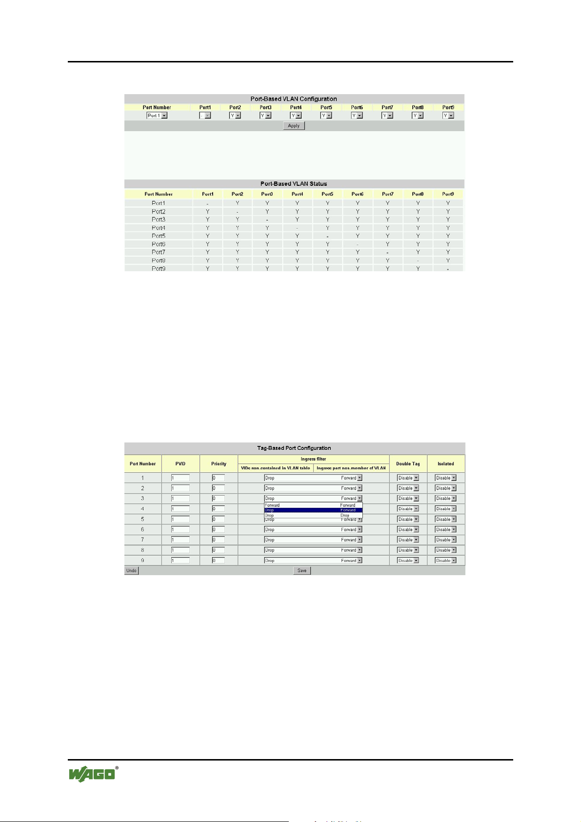
86 Configuration WAGO ETHERNET Accessories 852
852-104 7-Port 100BASE-TX + 2-Slot 100BASE-FX Industrial Managed Switch
SS14 – Port-based VLAN Configuration
Figure 75: Port-Based VLAN Configuration
The Menu Port-Based VLAN Configuration is for configuration of Port based
VLAN. It is enabled only when the VLAN Type is set as Port based.
At each port the user must click on the checkboxes of the ports to which the port
is allowed to switch frames from the configured port. And then click on [Save] to
retain newly entered information or click on [Undo] to restore previously saved
configurations.
SS15 – Tag-Based VLAN Port Configuration (Tagging Base/Port Info)
Figure 76: Tag-Based VLAN Configuration
The menu Tag-Based Port Configuration is for configuration of Tag based
VLAN. It is enabled only when the VLAN Type is set as Tag based. The sub
menu Port Info let users configure the way in which each port treats the incoming
frames that are marked for Tag-based VLANs.
Manual
Version 1.1.3
Page 87
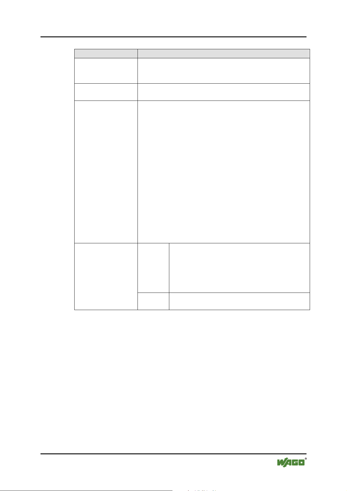
WAGO ETHERNET Accessories 852 Configuration 87
852-104 7-Port 100BASE-TX + 2-Slot 100BASE-FX Industrial Managed Switch
Table 36: Tag-Based VLAN Port Configura t i ons
Parameter Description
PVID
Set the VLAN ID. The limit given is between 1 and 4095.
The VLAN ID is assigned to all untagged frames received
on this port.
Priority
Set VLAN Priority. The limit given is between 0 … 7. 0 is
the lowest priority and 7 is the highest priority.
Ingress Filter 1
(Non-Member) and
Filter 2 (Untagged)
Non-Member (1): Forward
Untagged (2): Forward
• Forward the VLAN-tagged frames which are not
members of any VLAN in which the port is
participating, and forward all untagged frames.
Non-Member (1): Drop
Untagged (2): Forward
• Drop the VLAN-tagged frames which are not
members of any VLAN of which the port is
participating, and forward all untagged frames.
Isolated
Non-Member (1): Drop
Untagged (2): Drop
• Drop the VLAN-tagged frames which are not
members of any VLAN of which the port is
participating, and drop all untagged frames.
Enable
The port is isolated. Isolated ports belonging to
the same VLAN do not communicate with each
other – this is generally set for security reasons.
The isolated ports communicate only with the
trunk ports, which should NOT be set as
isolated.
Disable
The port is not isolated and can communicate
with all ports of the VLANs.
Manual
Version 1.1.3
Page 88
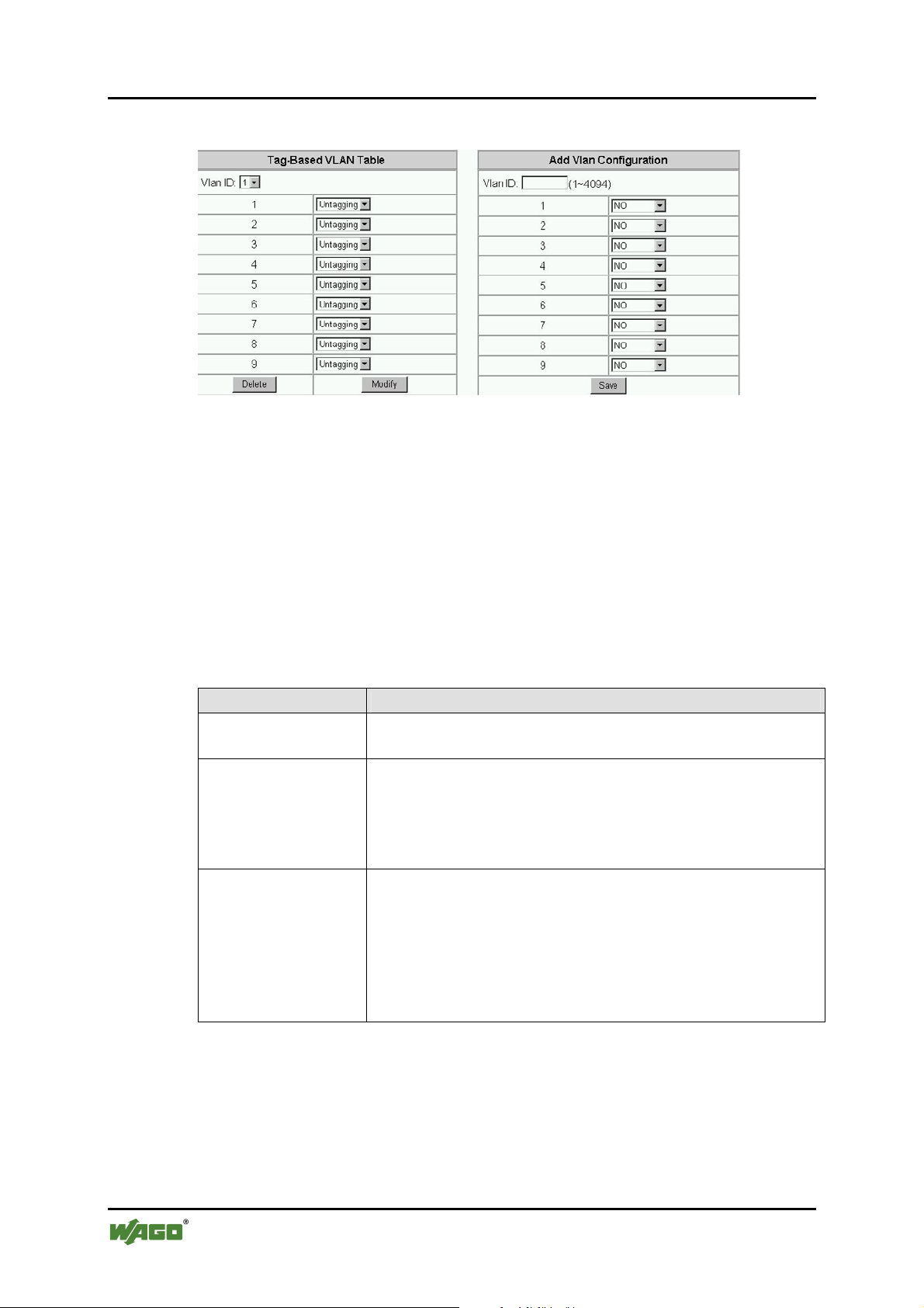
88 Configuration WAGO ETHERNET Accessories 852
852-104 7-Port 100BASE-TX + 2-Slot 100BASE-FX Industrial Managed Switch
SS16 – “Tag-based info” menu
Figure 77: Tag-Based VLAN Table
The sub-menu Tag-based info let users add, modify, or delete entries in the
Tagging VLAN Table, the configurations of 802.1Q VLANs and the participating
ports. Up to 64 VLANs can be configured on the Switch.
On the left is the Tag-based VLAN Table, where existing VLANs can be
modified or deleted. In the first row is the VLAN ID (VID) numbers (1, 2, etc.) of
the previously configured VLANs. Users can click on a VID number to display
the port information of that VLAN.
The following table describes the port parameters in regard to 802.1Q VLANs:
Table 37: Tag-Based Info Menu
Parameter Description
No
The port is not participating in the VLAN as identified by
the selected VID (VLAN ID).
Untagging
The port is an untagging port (as defined in 802.1Q) that is
participating in the VLAN. In such an untagged port the
Switch will strip off the 802.1Q tag from the incoming and
outgoing frames if they are tagged in such a way. This is
used for sending frames to non-802.1Q-compliant devices.
Tagging
The port is a tagging port (as defined in 802.1Q) and is
participating in the VLAN. The Switch will put the VLAN
information of the port – including VID and Priority – into
the header of the untagged frames coming in or transmitted
from the port. The tagged VLAN information in the frames
can later be used by other 802.1Q-compliant devices for
forwarding decisions.
Click the button [Modify] to modify configurations of the selected VLAN
according to the settings on the table.
Click the button [Delete] to delete the VLAN entries of the selected VID.
On the left is the Add Vlan Configuration” work area where you can add VLAN
configuration entries onto the Tagging VLAN Table. Enter a valid configurable
Manual
Version 1.1.3
Page 89
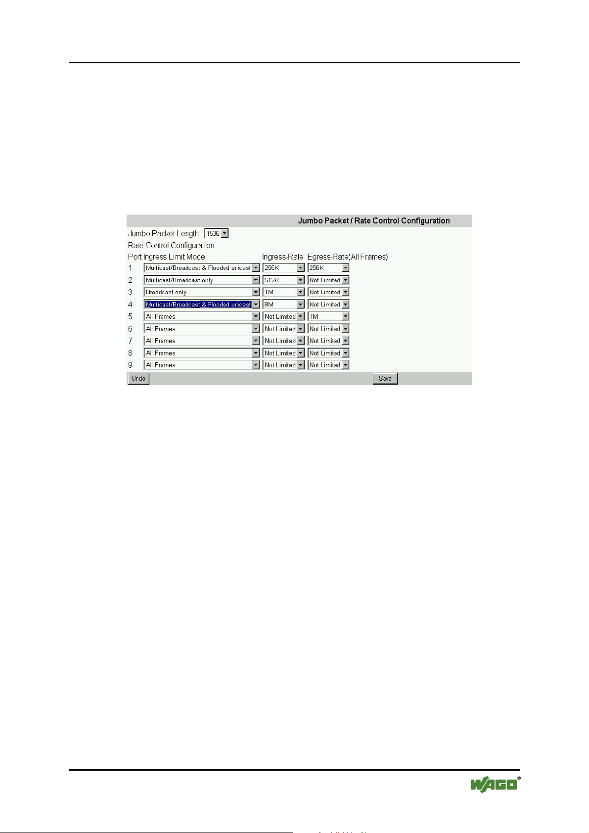
WAGO ETHERNET Accessories 852 Configuration 89
852-104 7-Port 100BASE-TX + 2-Slot 100BASE-FX Industrial Managed Switch
802.1Q VID ranging from 1 … 4094 into the field on the first row. Next, specify
for each port the parameters described in the table above – this will decide if the
specific port will participate in that specific VID and how it will participate. Click
the button [Save] to add the new VLAN to the Tagging VLAN Table.
SS17 - Packet Configuration
Use this screen to set the Jumbo packet limit and the Rate Control for each port of
the Switch.
Figure 78: Jumbo Packet
Click on each parameter field to modify the desired setting, then click on [Save]
to retain newly entered information or click on [Undo] to restore previously saved
configurations.
Manual
Version 1.1.3
Page 90

90 Configuration WAGO ETHERNET Accessories 852
852-104 7-Port 100BASE-TX + 2-Slot 100BASE-FX Industrial Managed Switch
Parameters described below:
Table 38: Jumbo Packet
Parameter Description
Jumbo Packet
Length
Select the size of packets:
1536 – For double-tagged packets or jumbo packets
1522 – For normally tagged packet. 1518 bytes are actually
allowed for untagged packets.
Port Ingress Limit
Select to block the specified traffic from the port.
Mode
Multicast Rate
Limit
• All Frames: – Restrict all kinds of packets (Default)
exceeding the rate set in the Ingress/Egress Rate
fields
• Multicast/Broadcast & Flooded unicast: – Restrict
these packets when exceeding the set value
• Multicast/Broadcast only: – Restrict these packets
when exceeding the assigned value
Ingress / Egress
Rate
• Broadcast only: – Restrict broadcast only packets
when exceeding the assigned limit
Set the threshold of traffic of limited packets for each port
in the Switch.
Manual
Version 1.1.3
Page 91
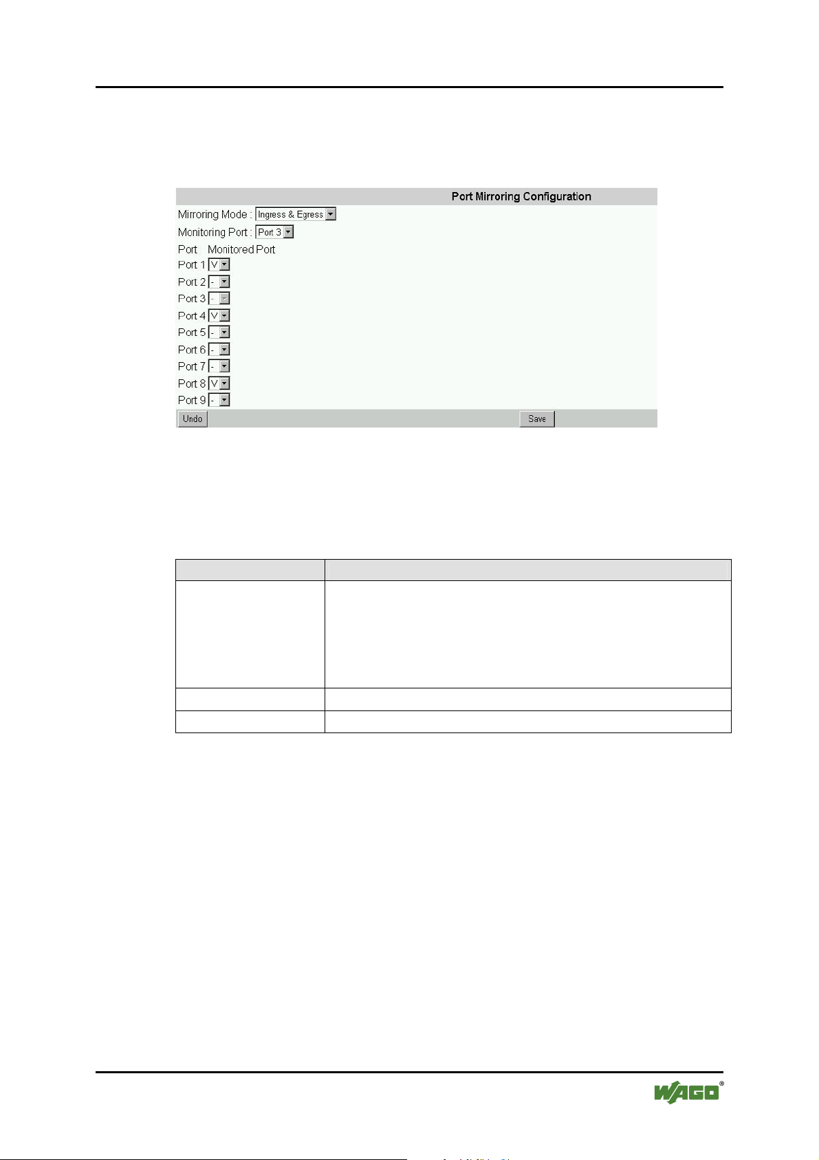
WAGO ETHERNET Accessories 852 Configuration 91
852-104 7-Port 100BASE-TX + 2-Slot 100BASE-FX Industrial Managed Switch
SS18 – Port Mirror
Set the port mirroring option to monitor data being transmitted through a specific
port.
Figure 79: Port Mirror
Click on each parameter field to modify the desired setting, then click on [Save]
to retain newly entered information or click on [Undo] to restore previously saved
configurations.
Table 39: Port Mirror
Parameter Description
Mirror Mode
Select appropriate mode:
- Disable: Mirror mode is disabled.
- Ingress & Egress: Monitor both incoming and outgoing
traffic.
- Egress: Monitor only outgoing traffic.
Monitoring Port
Monitored Port
Select the port which will do the monitoring.
Select the port that needs to be monitored.
Manual
Version 1.1.3
Page 92
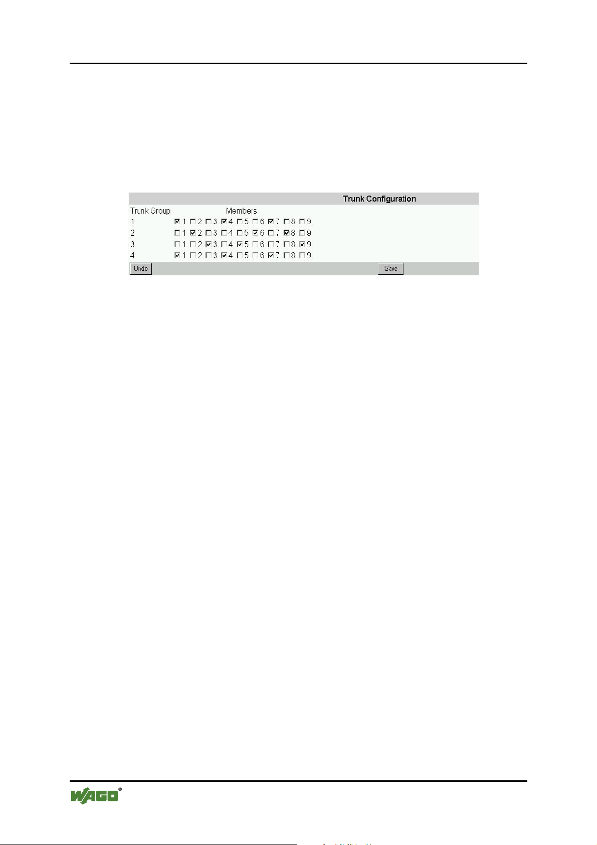
92 Configuration WAGO ETHERNET Accessories 852
852-104 7-Port 100BASE-TX + 2-Slot 100BASE-FX Industrial Managed Switch
SS19 – Trunk Configuration
Port Trunking defines a network link aggregation and trunking method which
specifies how to create a single high-speed logical link that combines several lowspeed physical links. Use the Trunk Configuration page shown below to create
trunk groups. The Switch supports a maximum of four trunk groups. Each trunk
group may be comprised of up to four ports, selected from any combination of
ports 1 … 8.
Figure 80: Trunk Configuration
Pos: 25.10.13 /Dokumentation allgemein/Gliederungselemente/---Seitenwechsel--- @ 3\mod_1221108045078_0.doc @ 21810 @ @ 1
Manual
Version 1.1.3
Page 93
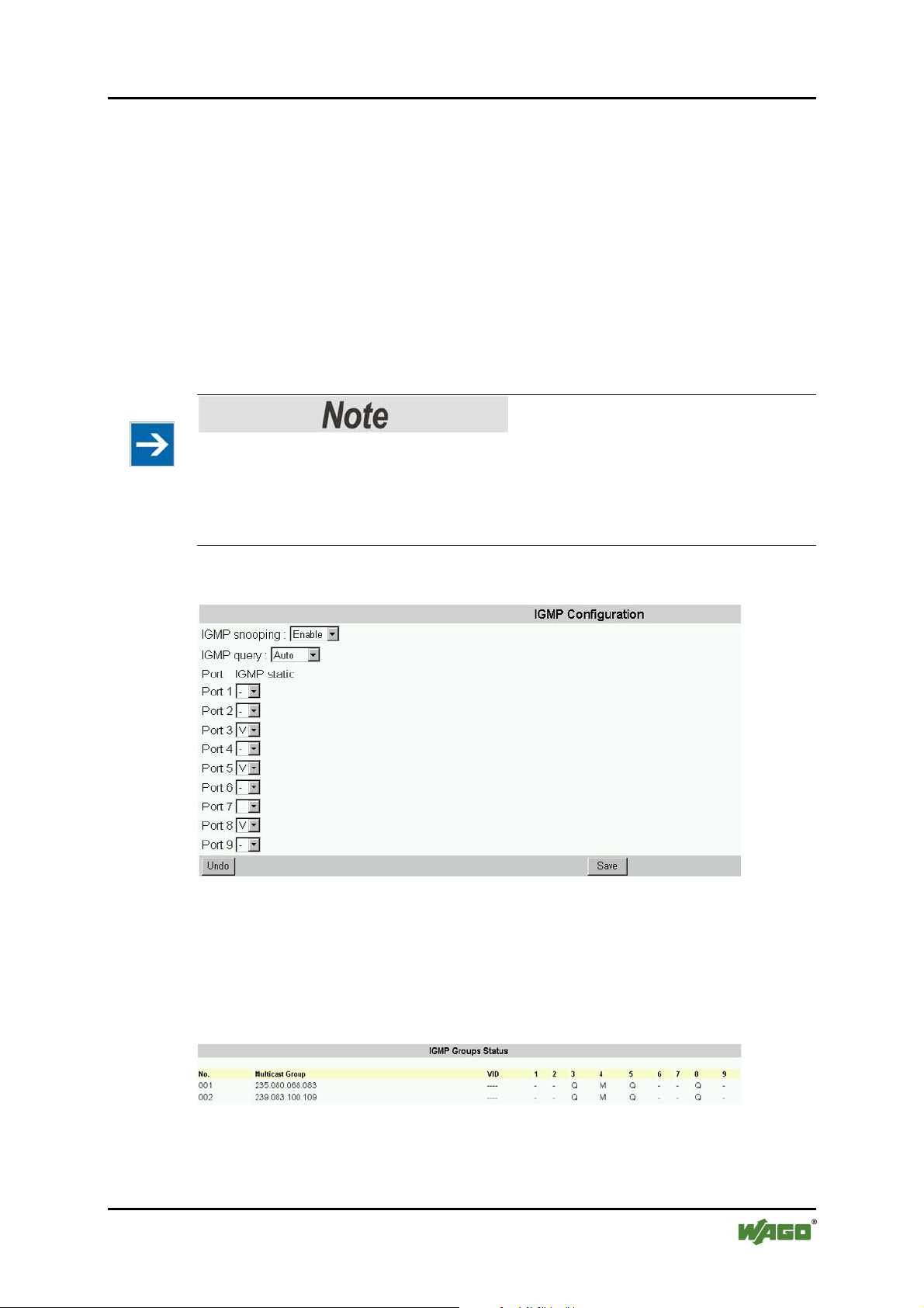
WAGO ETHERNET Accessories 852 Configuration 93
852-104 7-Port 100BASE-TX + 2-Slot 100BASE-FX Industrial Managed Switch
Pos: 25.10.14 /Serie 852 (Ethernet-Zubehör)/Konf iguration/C - Internetbrowser/IGMP Menu @ 3\mod_122286210 6500_21.doc @ 22915 @ 3 @ 1
8.4.7 IGMP Menu – Using the IGMP Menu
The IGMP menu is used for configuring IGMP snooping. IGMP means "Internet
Group Management Protocol". It is a protocol through which hosts can register
with their local router for multicast services. If there is more than one multicast
router on a given sub-network, one of the routers is elected and assumes the
responsibility of keeping track of group membership.
SS20 – IGMP Configuration
This menu allows the user to Enable/Disable IGMP Snooping and IGMP Query.
Please note
In order to keep the switch traffic efficient, the last byte of the IP address should
not be the same as in the IGMP group. E.g. if the Switch’s IP address is
192.168.0.10 and the IGMP router/switch’s IP address is 192.168.21.10, this will
make the switch less efficient.
Figure 81: IGMP Configuration
SS21 – IGMP Group Status
This window will display the IGMP group status of the port members if IGMP
traffic is present.
Figure 82: IGMP Group Status
Pos: 25.10.15 /Dokumentation allgemein/Gliederungselemente/---Seitenwechsel--- @ 3\mod_1221108045078_0.doc @ 21810 @ @ 1
Manual
Version 1.1.3
Page 94
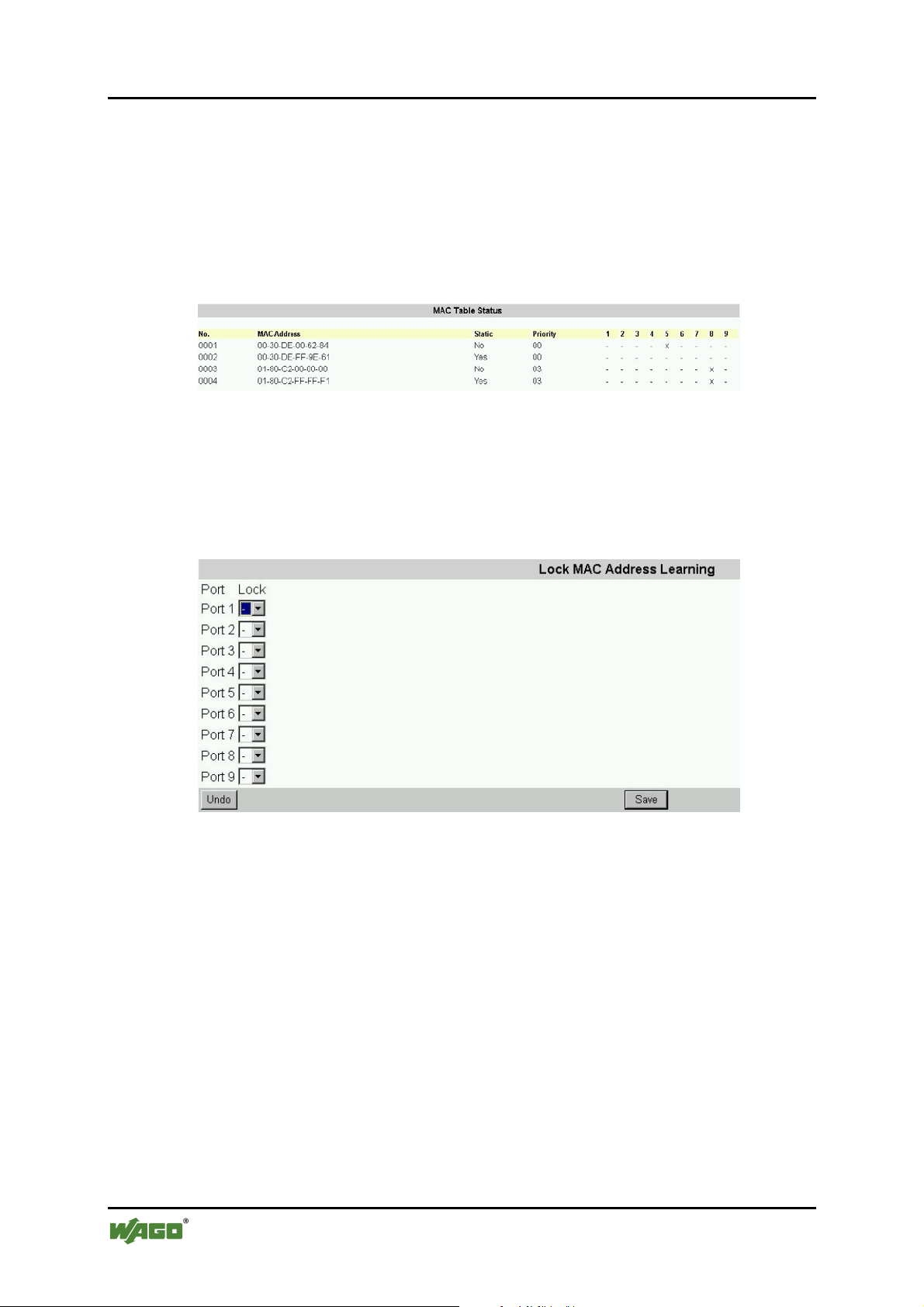
94 Configuration WAGO ETHERNET Accessories 852
852-104 7-Port 100BASE-TX + 2-Slot 100BASE-FX Industrial Managed Switch
Pos: 25.10.16 /Serie 852 (Ethernet-Zubehör)/Konf iguration/C - Internetbrowser/MAC Menu @ 3\mod_1222863 8309 68_21.doc @ 22924 @ 3 @ 1
8.4.8 The MAC Menu
The MAC menu will enable the following configurations:
SS22 – MAC Table Status
The user can view the MAC Table by selecting this function.
Figure 83: MAC Table Status
SS23 – Lock Learning MAC
The user can stop specific port(s) from learning MAC addresses. Select the port(s)
that need to be locked so that they cannot learn MAC addresses.
Figure 84: Lock Learning MAC
Manual
Version 1.1.3
Page 95
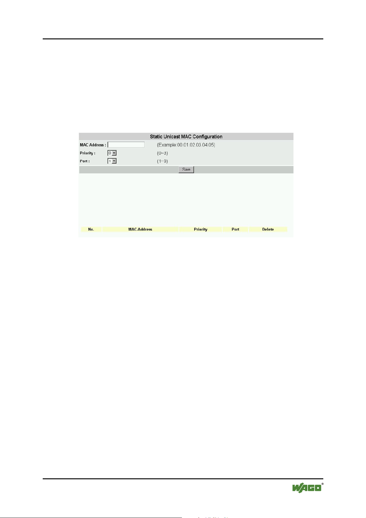
WAGO ETHERNET Accessories 852 Configuration 95
852-104 7-Port 100BASE-TX + 2-Slot 100BASE-FX Industrial Managed Switch
SS24 – Static MAC Configuration
Here the user can select a static MAC configuration for certain port(s) of the
Industrial Managed Switch.
Add the valid MAC address in the MAC field, then select the priority and port
number. Press [Save] to implement the input.
The Static MAC addresses and their settings will be displayed in the table below
the input bar. Press [Delete] to void the configuration.
Figure 85: Static MAC Configuration
Manual
Version 1.1.3
Page 96
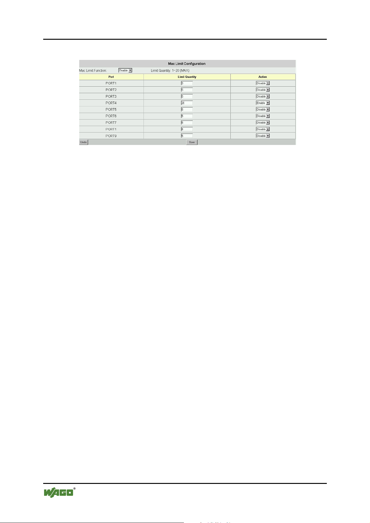
96 Configuration WAGO ETHERNET Accessories 852
852-104 7-Port 100BASE-TX + 2-Slot 100BASE-FX Industrial Managed Switch
SS25 – MAC Limit Configuration:
Figure 86: MAC Limit Configuration
The menu MAC Limit Configuration let the user limit the number of incoming
MAC addresses per port. If the user wants to disable this function, select
[Disable] from the combo box Mac Limit Function on the upper left. The Limit
Quantity range is 1 … 20 per port. The MAC addresses learned are recorded on a
per-port basis. Only the frames with such recorded MAC addresses will be
forwarded. This learning process will be conducted every 3 minutes. So, if users
change the NIC of the PC or IP appliance, the new MAC address will be learned
in 3 minutes by the Switch, with the set quantity limitations. The MAC Limit
Function can be disabled or enabled per port, under the parameter labeled Action
in the table. Generally this function is only enabled for downlink ports.
Pos: 25.10.17 /Dokumentation allgemein/Gliederungselemente/---Seitenwechsel--- @ 3\mod_1221108045078_0.doc @ 21810 @ @ 1
Manual
Version 1.1.3
Page 97
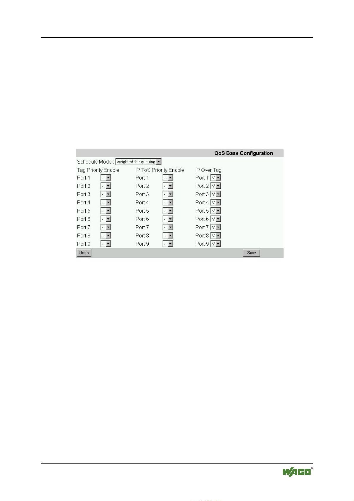
WAGO ETHERNET Accessories 852 Configuration 97
852-104 7-Port 100BASE-TX + 2-Slot 100BASE-FX Industrial Managed Switch
Pos: 25.10.18 /Serie 852 (Ethernet-Zubehör)/Konf iguration/C - Internetbrowser/QoS Menu @ 3\mod_1222865140 484_21.doc @ 22938 @ 3 @ 1
8.4.9 QoS Menu
QoS (Quality of Service) refers to the mechanisms in the Switch’s network
software that make the actual determinations of which packets have priority. The
Switch supports advanced QoS features like scheduling, classification and
policing.
SS26 – QoS Base Configuration
This window offers user to perform the basic configuration for Quality of Service.
Schedule Mode: weighted fair queuing/all high before low
Figure 87: QoS Base Configuration
Weighted Fair Queuing (WFQ) is a packet scheduling technique allowing
guaranteed bandwidth services. The purpose of WFQ is to let several sessions
share the same link.
Once you adjusted the basic settings, use the button [Save] to implement these
changes.
Manual
Version 1.1.3
Page 98
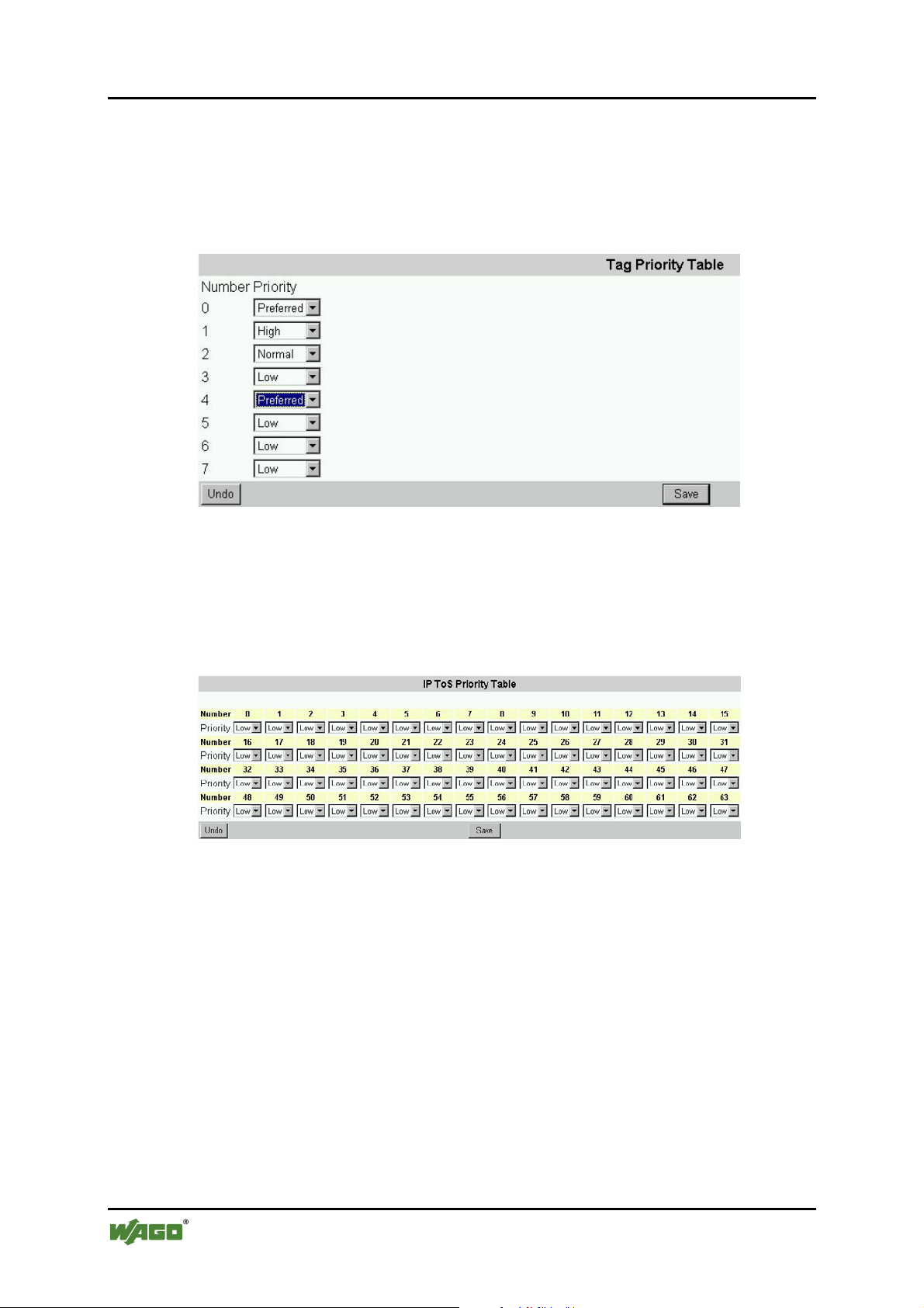
98 Configuration WAGO ETHERNET Accessories 852
852-104 7-Port 100BASE-TX + 2-Slot 100BASE-FX Industrial Managed Switch
SS27 – Tag Priority
The user can define up to eight different priority values for the Tagged VLAN
frames. Select the priority queue number for the Switch to map the MAC frames
into different priority queues: i.e. High, Medium, Normal or Low. Use [Save] to
apply the settings.
Figure 88: Tag Priority Table
Pos: 25.10.19 /Dokumentation allgemein/Gliederungselemente/---Seitenwechsel--- @ 3\mod_1221108045078_0.doc @ 21810 @ @ 1
SS28 – IP ToS Priority
The IP ToS (Type of Service) Priority menu provides up to 63 different priorities.
The user can select the most suitable combination.
Figure 89: IP ToS Priority Table
Manual
Version 1.1.3
Page 99
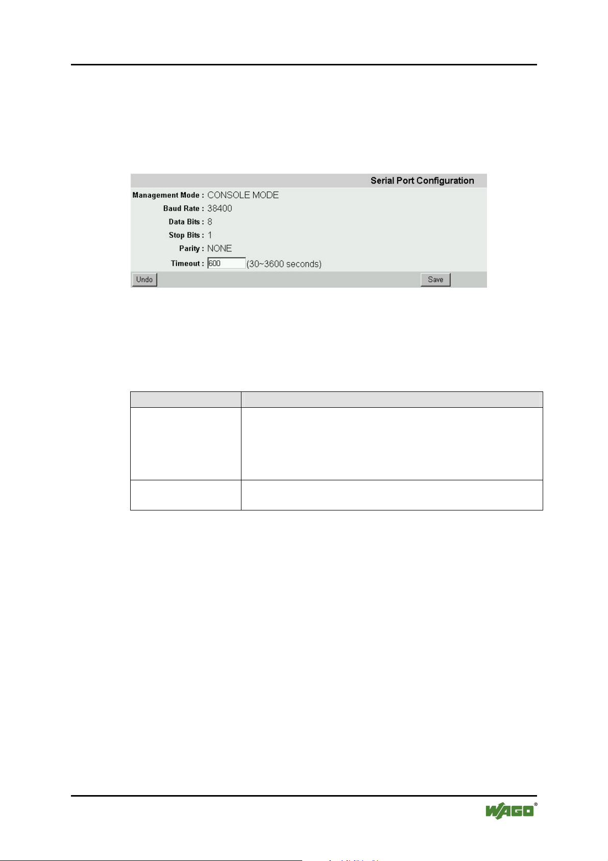
WAGO ETHERNET Accessories 852 Configuration 99
852-104 7-Port 100BASE-TX + 2-Slot 100BASE-FX Industrial Managed Switch
Pos: 25.10.20 /Serie 852 (Ethernet-Zubehör)/Konf iguration/C - Internetbrowser/Verwaltungskonf i guration @ 3\mod_1224492842734_21.doc @ 24250 @ 3 @ 1
8.4.10 Management Configurations
SS29 – Serial Port Configuration
Here the user can see the serial port configuration that can be utilized while
accessing the switch via Console port.
Figure 90: Serial Port Configuration
Click on each parameter field to modify the desired setting, then click on [Save]
to retain newly entered information or click on [Undo] to restore previously saved
configurations.
Pos: 25.10.21 /Dokumentation allgemein/Gliederungselemente/---Seitenwechsel--- @ 3\mod_1221108045078_0.doc @ 21810 @ @ 1
Table 40: Serial Port Configuration
Parameter Description
Management Mode
Default COM port properties
Baud Rate
Data Bits
Stop Bits
Parity
Time Out
Set the time (seconds) for auto-logout in case there is no
activity for that time period
Manual
Version 1.1.3
Page 100
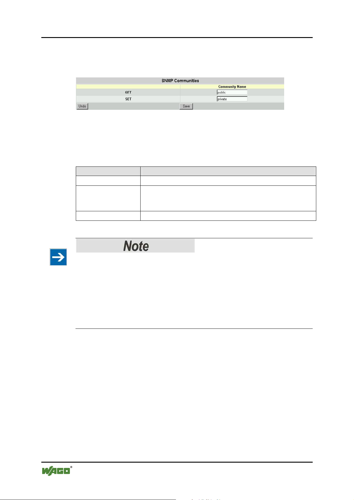
100 Configuration WAGO ETHERNET Accessories 852
852-104 7-Port 100BASE-TX + 2-Slot 100BASE-FX Industrial Managed Switch
Pos: 25.10.22 /Serie 852 (Ethernet-Zubehör)/Konf iguration/C - Internetbrowser/SNMP Konfiguration @ 3\ mod_1222865272218_21.doc @ 22941 @ 3 @ 1
8.4.11 SNMP Configurations
SS30 - SNMP Communities
Figure 91: SNMP Configuration
Click on each parameter field to modify the desired setting, then click on [Save]
to retain newly entered information or click on [Undo] to restore previously saved
configurations.
Table 41: SNMP Configuration
Parameter Description
GET
SET
Community Names
Community Name public - for reference only.
Community Name private - a group that can be renamed,
e.g. individuals that have access to this management
program.
Modify the Community names.
Please note
You can use an external SNMP-based application to configure and manage the
switch. This management method requires the SNMP agent on the switch and the
SNMP Network Management Station to use the same community string. This
management method, in fact, uses two community strings: the GET community
string and the SET community string. If the SNMP Network Management Station
only knows the SET community string, it can read and write to the MIBs
(Management Information Bases of the devices), but, if it only knows the GET
community string, it can only read the MIBs.
The default GET and SET community strings for the switch is public.
Manual
Version 1.1.3
 Loading...