


787-840
Anschluss
Connection
T
Um Verwechslungen mit anderen
Anschlüssen zu vermeiden, verwenden Sie
ausschließlich die mitgelieferten Stecker.
T
To re duce th e ri sk of mis tak ing the
terminals, the supplied terminals must
be used.
1
2
3
4
PE L1 L2 L3
a
b
Eingang
line
+ + – –
Ausgang
load
U
out
+–
Ab b ild u ng ze i gt den 787- 842
Thi s figu r e sho w s the 78 7- 8 42
1
2
3
4
5
6
7
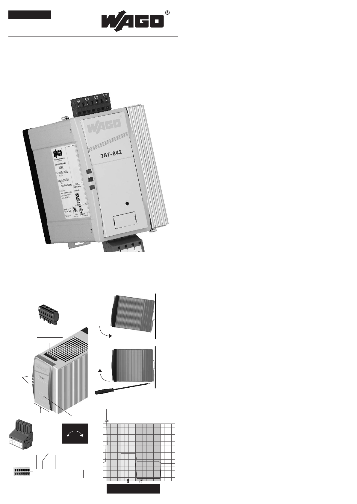
LED: Die grüne LED (a) leuchtet,
sofern die Ausgangsspannung größer
als der Power-Good-Schwellenwert
ist. Die rote LED (b) leuchtet, sofern
die Ausgangsspannung kleiner als der
Power-Good-Schwellenwert ist.
Ausgangsspannung: Die Aus-
gangsspannung kann mit einem
Schraubendreher verändert werden.
Drehung im Uhrzeigersinn erhöht die
Ausgangsspannung. Drehung gegen
den Uhrzeigersinn verringert die
Ausgangsspannung.
Eingang (schwarzer Stecker) line
Ausgang (bla uer Ste c ker) load
Montage: Setzen Sie das Gerät mit
de r Trags c hie n enfüh rung an die Ob er-
ka n te der Tra gsc h ien e an und ra sten
Si e es nac h unten ei n.
Demontage: Ziehen Sie den
Schnappriegel mit Hilfe eines
Schraubendrehers auf und hängen
Sie das Gerät an der Unterkante der
Tragschiene aus.
Überstromverhalten: Power Boost
un d Top Boo s t .
Potenzialfreier Meldekontakt: Bei
Unterspannung am Ausgang wird das
interne Relais inaktiv. Diese Störung
kann über den Wechselkontak t abge-
fragt werden.
Stand-by-Eingang: Der St a nd- b y -
Eingang ermöglicht ein gezieltes
Ausschalten der Stromversorgung.
Durch das Anlegen einer externen
Gleichspannung am Stand-by-Eingang
wi r d der Au sgan g des Ge r ätes ab ge-
schaltet und die Stromversorgung
verbleibt im Bereitschaftszustand.
1
2
3
4
5
6
7
LED: The green LED (a) lights as soon
as the output voltage is larger than
the power-good-threshold. The red
LED (b) lights if the output voltage is
lower than the power-good-threshold.
Output voltage: The output voltage
ca n be alter e d usi n g a scr e w dri v e r.
Turning the adjustment screw
clock wise raises the output voltage.
Tur ning th e adj ustme n t scr e w antic l o-
ck w i se redu ce the ou t put vo l tage .
Input (black plug) line
Output (blue plug) load
Mounting: Place the unit with the DIN
rail guide on the upper edge of the DIN
rail, and snap it in with a
downward motion.
Removing: Pull the snap lever open
with the aid of a screwdriver and slide
the module out at the lower edge of
the DIN rai l.
Overload current behaviour: Power
Bo o s t and Top Boos t .
Isolated signal contact: In the event
of undervoltage at the output, the
internal relay becomes inactive. This
er r or can be queri e d via th e chan geo-
ver contact.
Stand-by-input: The stand-by-input
allows targeted switch-off of the
power supply. By applying an external
DC voltage at the standby-input, the
output of the device is not released
and the power supply remains on
stand-by.
Sicherheitsmaßnahmen vor der
Installation
Das Betriebsmittel ist vor unzulässiger
Beanspruchung zu schützen. Insbesonde-
re dürfen bei Transport und Handhabung
keine Bauelemente verbogen und/oder
Isolationsabstände verändert werden.
Die Berührung elektrischer Bauelemente
und Kontak te ist zu vermeiden. Das
Betriebsmittel immer im spannungsfreien
Zustand montieren und verdrahten. Die
Produktbeschreibung und die technischen
Hinweise in unserem Hauptkatalog sowie
die Aufschrif ten am Betriebsmittel und
au f dem Typen schi ld si n d zu be a chten .
Installation
Die Installation ist entsprechend den
örtlichen Gegebenheiten, einschlägigen
Vorschriften (z. B. VDE 0100), nationalen
Un f allv e rhü t u ngs v orsc h riften (z . B. UV V-
VBG4 bzw. BGV A3) und den anerkannten
Regeln der Technik durchzuführen.
Dieses elektrische Betriebsmittel ist eine
Komponente, die zum Einbau in elektrische
Anlagen oder Maschinen bestimmt ist und
erfüllt die Anforderungen der Niederspan-
nungsrichtlinie (2014/35/EU). Um eine
ausreichende Konvektion zu gewährlei-
sten, sind folgende Mindestabstände zu
benachbarten Modulen empfohlen: 40mm
oben und unten, 10mm auf der linken und
rechten Seite. Bei Einbau in Maschinen
is t die Au f n ahm e des be s t imm ungs ge-
mäßen Betriebes solange untersagt, bis
festgestellt wurde, dass die Maschine den
Bestimmungen der Maschinenricht-linie
(2006/42/EG) entspricht.
EN 60204 ist zu beachten. Die Aufnahme
des bestimmungsgemäßen Betriebes
ist nur bei Einhaltung der EMV-Richtlinie
(2014/30/EU) erlaubt. Die Einhaltung der
durch die EMV-Gesetzgebung geforderten
Grenzwerte liegt in der Verantwortung
des Herstellers der Anlage oder Maschi-
ne.
Safety measures before installation
This equipment is to be protected against
improper use. Components are not to
be be nt or is olat i on sp a cin g chan g ed, es -
pecially through handling and transport.
The contact with electrical components
and terminals is to be avoided. Always
disconnect the equipment from the mains
supply, before commencing installation or
wiring. The product description, technical
information in our main catalogue and the
marking on the equipment ratings plate
ar e to be obs e r ved.
Installation
In s tall atio n must be carri e d out ac c or-
ding to the prevailing local conditions
and safety regulations (e.g. VDE 0100)
national accident prevention regulations
(e . g. UV V- V B G4 or BG V A3) an d the ge -
nerally accepted rules of technology. This
equipment is a component designed for
installation into electrical systems and
machines, and fulfils the requirements of
the low voltage guidelines (2014/35/EU).
In order to ensure sufficient convection,
fol low in stal l atio n clear ance s is reco m -
mend: 40mm on top and bottom, 10mm
on the left and right side. When installed
into machinery, the normal operation is
forbidden until it is determined that the
machine fulfils the requirements of the
machinery guidelines (2006/42/EG). EN
60 204 mu st be ob s erve d . The EM C re -
qu ireme nts (20 14 / 30/ E U) must be fulfil -
led before operation is commenced. The
observance of the required limitations for
the EMC legislation is the responsibility
of the manufacturer of the installation or
machinery.
Installation
Installation
6
5
DIN 35 mm
rail
7
787-840/842/844/845/847 / 2016•02
deutsch / english
Bedienungsanleitung / Instruction Manual
Stabilisierte Stromversorgung
Stabilised power supply
EPSITRON
®
-PRO-Power 787-840
787-842
787-844
787-845
787-847
Top Boost
Power
Boost
Strombegrenzung
Current limitation
U
out
[V]
t [sec]
I
out
[%]
Überstromphase
Overcurrent phase
Stufe 1
Step 1
Stufe 2
Step 2
Unenn
Urated
Inenn
Irated
Relais akt iv (Kont akt 1-2 geschlo ssen),
we nn Uo ut > Pow er- Goo d- Sch wel lwe r t.
Relay active (contact 1-2 closed),
if Uo ut > p owe r-g ood -t hre sho ld .
89
12345678
Stand-by
8
8
9
9
potenzialfreier DC-OK Ausgang und
Stand-by Eingang ab Fertigungsauf-
tragsnummer 101432 verfügbar.
Potential-free DC-OK output and
Sta n d-by input ava ila b le fr om pr o -
du c t ion numbe r 101432 .

Technische Daten
Technical data
787-840 787-842 787-845 787-8 44 787-847
Schaltnetzteil, dreiphasig e, primär getakte te Einbaus tromversorgung für
TH35-Tragschienenmontage
Primary switched mode supply, t hree phase primary switched mode power supply
co mpo ne nt fo r mou nt ing on DI N 35 mm rai l s
No rm en Safety standards
Sicherheit Safety EN 6095 0, UL 609 50 , UL 50 8
EM V EMC EN 612 0 4- 3 (Pr odu kt nor m) EN 61 20 4-3 (p ro duc t st and ar d)
Schutzkleinspannung
Sa fet y ext r a- low vol tag e
EN 60950 (SELV) und EN 60204 (PELV)
EN 6095 0 (S E LV ) an d EN 60 20 4 ( PE LV)
Zulassungen Approvals
UL /CS A 60 950
UL 508 li st ed / CS A 22 .2 No .1 07.1 3r d Ed . lis ted
ja yes
Um we lt Environment
Umgebungstemperatur (UL-konform)
Am bie nt te mpe rat ure (UL co n fo r m)
–2 5 °C … +70 °C, De ra tin g: -3 % /K > +5 0 °C
–2 5 °C … +55 °C , D er ati ng: -5 %/ K > +4 5 °C
40 0 Va c . .. 500 Vac, De ra t in g: -0 ,5 Ad c/ 10 Vac > 44 0 Va c
An lau f bei -4 0 °C ty pge pr üft De v ic e s ta rt at -4 0° C ty pe- t es ted
Lagertemperatur Storage temperature –2 5 °C … +8 5 °C
Kühlart Cooling
Selbstkühlung durch natürliche Konvektion bei vertikaler Einbaulage
AN (N at ura l ai r con ve cti on co ol ing )
Zulässige Luftfeuchtigkeit
Allowable humidity
5 bi s 96 % re la tiv e F eu cht e , ke ine Beta uun g zu läs si g
5 to 96 % r el a ti ve hu mi di ty wi th no de w
Si ch erh ei t und S ch ut z Safety and protection
Prüfspannung HV t es t vol t ag e 42 42 Vdc (P ri. -Se c .) / 2200 Vdc (P ri . PE ) / 700 Vdc (Sek .-P E)
Überspannungskategorie
Overvoltage category
II
Ba ua rt
Construction
gekaps elt, für den Einbau im Schaltsc hrank
enclosed for installation in switching cabinets
Schutzart Protection index IP 20 (nach EN 60529) IP 20 (to EN 6 05 29 )
Schutzklasse
Safety class
I
Anschlusskabel
Conductors
Zu m Ans ch lus s Ku p fe r ka bel mit mi n. 75 ° C ve r we nde n
Us e Cop pe r Con du c to rs on ly , r at ed 75 ° C
Einsatzbereich
Installation
Ei ns atz in B er eic he n mit Ver sch mu tzu ngs gr a d 2
For installation in Pollution Degree 2 environment
Rückspeisungsfestigkeit Fee dba ck vo lt age ma x . 35 Vdc ma x . 63 Vdc ma x . 35 Vdc ma x . 63 Vdc
Eingangsdaten Input
Eingangsnennspannung Rated input voltage 3/ 2 x 400 – 500 Vac
Eingangsspannungsbereich
Operating input voltage range
340 – 550 Vac (480 – 780 Vdc)
Frequenzbereich
Ra t ed fr eq uen cy ra ng e
50 Hz – 60 Hz
Ei ng ang sn en nst r om bei 3x 34 0 Vac
Ra t ed inpu t cur ren t at 3x 34 0 Vac
0, 6 Aa c (24 Vd c/10 Ad c) 1,1 Aac (24 Vdc/20 Adc) 1,1 Aac (48 Vdc/10 Adc) 2,0 Aac (2 4 Vd c/ 40 Adc) 2,0 Aac (4 8 Vd c/2 0 Ad c )
Ei ng ang sn en nst r om bei 2x 340 Vac
Ra t ed inpu t cur ren t at 2x 340 Vac
1, 2 A ac (24 Vdc /10 Ad c) 2,1 Aac (24 Vdc/20 Adc) 2,1 Aac (48 Vd c/ 10 Adc) 2 ,6 Aa c (2 4 Vd c/2 5 Ad c ) 2,6 Aac (48 Vd c/12,5 Adc)
Einschaltstrom (kalt) In-rush current (cold) <3 0 Ap
Eingangssicherung intern
Internal fuse
3 x 2, 5 AT 3 x 2, 5 AT 3 x 3, 2 AT
Ex ter ne Ab si che ru ng (U L-k onf orm )
External protection device (UL-recognised)
nicht erforderlich
not necessary
Empfohlene externe Absicherung*
Re c om me nde d ex ter nal p ro tec tio n*
3 x Le i tu ngs sc hut z sc hal t er 6 A, 10 A od er 16 A, Ch ara kt eri s ti k B , C
3 x Ci rcu it br eak er s 6 A, 10 A or 16 A
Motorschutzschalter
Ei ns tel l we r t 1, 6 A
Ei ns tel lbe rei ch 1, 6 – 2, 5 A
Motor protection switch
Se tti ng va lu e 1 .6 A
Ad ju stm en t ran ge 1. 6 – 2. 5 A
Motorschutzschalter
Ei ns tel l we r t 2, 5 A
Ei ns tel lbe rei ch 2, 5 – 4, 0 A
Motor protection switch
Se tti ng va lu e 2 .5 A
Ad ju stm en t ran ge 2. 5 – 4. 0 A
Motorschutzschalter
Ei ns tel l we r t 3, 2 A
Ei ns tel lbe rei ch 2, 5 – 4, 0 A
Motor protection switch
Se tti ng va lu e 3 .2 A
Ad ju stm en t ran ge 2. 5 – 4. 0 A
Ableitstrom Leakage current ty p. 1 mA
Ne t za usf al lüb er brü cku ng be i 40 0 / 500 Va c
Ma in s dro p co mpe ns a ti o n at 40 0 / 50 0 Va c
22 ,6 / 51, 5 ms 13 ,2 / 36 ,8 ms 12 / 35 ms 15 ,6 / 42 ,9 ms 15 ,6 / 42 ,9 ms
Überspannungsschutz
Over voltage protection
du rch Var ist o r im Pr im är str omk re is
th r ou gh va ri sto r in pr im ary ci rc uit
Anschlüsse: WAGO Multisteckersystem
Ter min al s: WAG O mu l ti pl ug sys tem
WAG O Ser ie 231 , max . 2,5 m m²
WAG O ser ie s 231, ma x . 2. 5 mm ²
Ausgangsdaten Output
Ausgangsnennpannung
Ra t ed ou tp u t vo l ta ge
24 Vd c ±1 % 24 Vdc ±1 % 48 Vdc ±1 % 24 Vdc ±1 % 48 Vdc ±1 %
Ausgangsspannungsbereich
Ra t ed ou tp u t vo l ta ge ra ng e
22 ,8 – 28 ,8 Vdc 22,8 – 28,8 Vdc 39 – 53 Vdc 22 ,8 – 28 ,8 Vdc 3 9 – 53 Vd c
Be m es su ngs st rom bei U
nenn
Ra t ed ou tp u t cu r re n t at U
rated
10 Adc 20 Adc 10 Adc 40 Adc 20 Adc
Power Boo st **
(b e i Be tri eb vo n 3 Ei n ga ng sphas en )
Power Boo st **
(i f ope ra tio n wit h 3 i np ut ph as e s)
20 Adc / 4 s
(1 5 Ad c / 16 s)
40 Adc / 4 s
(3 0 A / 16 s)
15 Adc / 4 s
(1 2, 5 A / 16 s)
60 Adc / 4 s
(5 0 A / 16 s)
30 Adc / 4 s
(2 5 A / 16 s)
Dauerh aft zu entne hmender Ausgangss trom bei
Be tri eb vo n nu r 2 Ein ga n gs ph ase n
Conti nuous outp ut curren t allowed if only oper ated
wi th 2 in pu t pha se s
10 Adc 20 Adc 10 Adc 25 Adc 12,5 Adc
Power Boo st bei Betrieb von nur
2 Eingangsphasen
Power Boo st if only operat ed with
2 input phases
20 Adc / 4 s 25 Adc / 4 s 12, 5 Ad c / 4 s 40 Ad c / 4 s 20 Ad c / 4 s
Top Bo os t Top Boos t 70 Adc 80 Adc 55 Adc 100 Adc 80 Ad c
Strombegrenzung Current limitation ty p. 1, 1 x I
nenn
ty p. 1. 1 x I
rated
Wirkungsgrad Ef fi cie nc y ty p. 91 ,7 % ty p. 92 ,9 % ty p. 93 % ty p. 93, 6 % ty p. 94 ,4 %
max. Verlu stleistung Lee rlauf / Nennlas t max.
Po w er loss idl ing / n om in al lo ad
7,8 / 19, 9 W 8,3 / 34 ,1 W 8,2 / 38 W 7,0 / 61 ,5 W 5 ,2 / 59,2 W
Restwelligkeit Residual ripple ty p. 70 mVp p
Parallelschaltbarkeit Parallel operation ja, zur Leistungserhöhung ye s, fo r inc rea se d pow er
 Loading...