

Page 1
UNIVERSAL SPRAYER
W 570 FLEXIO
ORIGINAL
BETRIEBSANLEITUNG
wagner-group.com
D GBNLF
Page 2
5-15 cm
20-30 cm
2333118_Testposter_W577.indd 1 19.11.2012 14:22:56
W 570 Flexio
ÜBERSICHT / OVERVIEW / APERÇU GÉNÉRAL / OVERZICHT
8
9
7
6
5
4
10
19
11
18
3
1/2
14
13
WallPerfect Flexio 585 I-Spray
A B C D E F
I-Spray
1
3
I-Spray
Cover up !
+
20-30 cm
– +
2
1
1
3
4
3
3
Testposter
12
-
1 4
17
Materialnr. 233 3118 EBSS
16
A
B
15
Page 3
W 570 Flexio
click
c
a
b
1
A B
Page 4
W 570 Flexio
+
5-15 cm
20-30 cm
W
A
L
L
&
C
E
I
L
I
N
G
W
O
O
D
&
M
E
T
A
L
AIR POWER
1
2
A B C
1
A
C
B
Page 5
W 570 Flexio
1
5
1
2 3
1
2
3
64
7
6
5
Page 6
W 570 Flexio
3
5
4
2
1
3
1
2
Page 7
W 570 Flexio
1.
2.
6
5
7
8
4
9
10
11
123
5
34
6
7
8
12
9
Page 8
W 570 Flexio
............................................. 78
ERSATZTEILE / SPARE PARTS / PIÈCES DE RECHANGE / ONDERDELEN
2
1
1
3
4
..........................................................................1 - 19
D
........ ........................................................................20 - 38
GB
........................................................................39 - 57
F
........................................................................58 - 76
NL
++
Fragen? · Questions? · Des questions? · Vragen?
Page 9

GB
W 570 Flexio
Translation of the original operating instructions
MANY THANKS FOR PLACING YOUR TRUST IN US
We would like to congratulate you on purchasing this brand product from Wagner;
we are sure that you will enjoy working with it greatly.
Please read the Operating Manual carefully and observe the safety information
before starting the device. Store the Operating Manual in a safe place close to the
product in case it needs to be used by someone else.
We would be happy to be of assistance if you have any questions, suggestions or requests.
Please contact us via the phone number included on the back page or via our homepage,
www.wagner-group.com/service.
Contents
1. Explanation of symbols used ................................................... 21
2. General Safety Instructions .................................................... 21
3. Safety Instructions for Spray Guns .............................................. 24
4. Description/ Scope of delivery .................................................25
5. Field of application ............................................................25
6. Coating Materials Suitable for Use .............................................. 25
7. Coating Materials Not Suitable for Use .......................................... 26
8. Preparation of the workplace (for interior wall paint) ............................26
9. Preparation of the Coating Material ............................................26
10. Start-up ...................................................................... 27
11. Selecting the Spray Setting (Wall Extra I-Spray spray attachment) ..............27
12. Selecting the Spray Setting (Standard spray attachment) ......................28
13. Adjusting the Material Volume (Fig. 8) .........................................28
14. Setting the Amount of Air (Fig. 9) .............................................. 28
15. Spray Technique .............................................................. 29
16. Interruption of Work ..........................................................29
17. Taking Out of Operation and Cleaning .........................................30
18. Cleaning the Wall Extra I-Spray spray attachment .............................30
19. Cleaning the Standard spray attachment .....................................31
20. Maintenance ................................................................. 32
21. Spare Parts ...................................................................33
22. Accessories ................................................................... 34
23. Correction of Malfunctions ....................................................34
24. Technical Data ................................................................ 35
25. Environmental protection. . . . . . . . . . . . . . . . . . . . . . . . . . . . . . . . . . . . . . . . . . . . . . . . . . . . . 36
20
Page 10

W 570 Flexio
i
26. Important Note regarding Product Liability! ................................... 36
3+1 years guarantee .............................................................37
CE Declaration of Conformity ..................................................... 77
GB
1. Explanation of symbols used
This symbol indicates a potential danger for you or for the device.
Under this symbol you can nd important information on how to
avoid injuries and damage to the device.
Danger of electrical shock
Indicates tips for use and other particularly useful information.
Devices and accessories marked with this symbol are suitable for
processing low-viscosity materials such as paints, glazes and wall
paints specically designed for this purpose.
If a material bears this logo, it is particularly well suited for use with
the relevant device.
Devices and accessories marked with this symbol are suitable for
processing high-viscosity materials such as e.g. interior wall paints
(dispersions and latex paints).
If a material bears this logo, it is particularly well suited for use with
the relevant device.
2. General Safety Instructions
WARNING! Read all safety notications and instructions. Failure to comply with the
safety notications and instructions provided may result in electric shock, re
and/or serious injury. Save all warnings and instructions for future reference.
The term "power tool" used below covers both mains-operated power tools (with
mains lead) and accumulator-operated power tools (without mains lead).
1. Safety at the workplace
a) Keep your workplace clean and well lit. Disorder or unlit workplaces may result in
accidents.
b) Never use the tool in hazardous areas that contain ammable liquids, gases
or dusts. Power tools generate sparks that can ignite the dust or vapors.
c) Keep children and other persons away when using the power tool. You can
lose control of the tool if you are distracted.
21
Page 11

GB
W 570 Flexio
2. Electrical Safety
a) The tool plug must t into the socket. The plug may not be modied in any
form. Do not use adaptor plugs together with protective-earthed tools.
Unmodied plugs and suitable sockets reduce the risk of an electric shock.
b) Avoid physical contact with earthed surfaces such as pipes, heating
elements, stoves and refrigerators. The risk through electric shock increases if
your body is earthed.
c) Keep the equipment away from rain and moisture. The risk of an electric shock
increases if water penetrates electrical equipment.
d) Do not misuse the mains lead by carrying the tool by the lead, hanging it
from the lead or by pulling on the lead to remove the plug. Keep the lead
away from heat, oil, sharp edges or moving tool parts. Damaged or twisted
leads increase the risk of an electric shock.
e) If you work outdoors with a power tool, only use extension cables suitable
for outdoor use. The use of an extension lead that is suitable for outdoors reduces
the risk of an electric shock.
f) If you cannot avoid using the tool in a damp environment, use a residual
current operated circuit-breaker. Using a residual current operated circuit-breaker
avoids the risk of electric shock.
3. Safety of Persons
a) Be attentive. Pay attention to what you are doing and work sensibly with
a power tool. Do not use the tool if you are tired or under the inuence of
drugs, alcohol or medication. Just a moment of inattentiveness while using the
tool can lead to serious injuries.
b) Wear personal safety equipment and always wear safety goggles Wearing
personal protective equipment, such as dust mask, non-slip safety shoes, safety helm
or ear protection, depending on the type of power tools, reduces the risk of injury.
c) Avoid accidental starting-up. Make sure that the electric tool is switched o
before you connect it to the power supply, pick it up or carry it. Accidents can
occur if you carry the power tool while your nger is on the switch or if you connect
the power tool to the power supply which it is on.
d) Remove setting tools or wrenches before switching on the power tool. A tool
or wrench that is in a rotating tool part can lead to injuries.
22
Page 12

W 570 Flexio
e) Avoid an unnatural posture. Ensure that you are standing securely and
have your balance at all times. This ensures that you can control the tool better in
unexpected situations.
f) Wear suitable clothing. Do not wear wide clothing or jewellery. Keep your
hair, clothes and gloves away from moving parts. Loose clothing, jewellery or
long hair can be caught in moving parts.
4. Usage and treatment of the electric tool
a) Do not overload the tool. Use the power tool designed for the work that you
are doing. You work better and safer in the specied performance range if you use
the suitable power tool.
b) Do not use power tools whose switch is defective. A power tool that cannot be
switched on or o is dangerous and has to be repaired.
c) Remove the plug from the socket before carrying out tool settings, changing
accessories or putting the tool away. This precautionary measure prevents
unintentional starting of the tool.
d) Store unused power tools so that they are inaccessible to children. Do not
let persons use the tool who are not familiar with it or who have not read
these instructions. Power tools are dangerous when they are used by inexperienced
persons.
GB
e) Take proper care of your tools. Check whether the moving parts
functiontrouble-free and do not jam, whether parts are broken or damaged
so that the tool function is impaired. Have damaged parts repaired before
using the tool. Many accidents have their origin in power tools that have been
maintained badly.
f) Use the power tool, accessories, insert tools, etc. in accordance with these
instructions and in a fashion specied for this special tool type. Take the
working conditions and the activity to be carried out into consideration. The
use of power tools for purposes other than the intended ones can lead to dangerous
situations.
5. Service
a) Have your tool repaired only by qualied specialist personnel and only with
original spare parts. This ensures that the tool safety is maintained.
b) If the supply cord is damaged, it must be replaced by the manufacturer or it’s
service agent or a similarly qualied person in order to avoid a safety hazard.
23
Page 13

GB
W 570 Flexio
3. Safety Instructions for Spray Guns
Caution! Wear breathing equipment: Paint mist and solvent vapors are damaging to
•
health. Always wear breathing equipment and only work in well ventilated rooms or
using supplementary ventilating equipment. It is advisable to wear working clothing,
safety glasses, ear protection and gloves.
CAUTION: DANGER OF INJURY!
Never point the spray stream towards human beings or animals.
Sockets and plugs must be masked. Risk of an electric shock as a
consequence of sprayed material entering the socket!
Attention! Never operate the device if the nozzle seal is either
damaged or missing. If the nozzle seal is either missing or damaged
liquids can enter the device and increase the risk of an electric shock.
Check the nozzle seal before each use.
Do not use the spray guns to spray ammable substances.
•
The spray guns are not to be cleaned with ammable solvents.
•
Caution against dangers that can arise from the sprayed substance and observe the
•
text and information on the containers or the specications given by the substance
manufacturer.
Do not spray any liquid of unknown hazard potential.
•
The device may not be used in workplaces covered by the explosion-protection
•
regulations.
To avoid the hazard of explosion when spraying, provide for eective natural or
•
articial ventilation.
There must be no sources of ignition such as, for example, open res, smoke of lit
•
cigarettes, cigars and tobacco pipes, sparks, glowing wires, hot surfaces, etc. in the
vicinity during spraying.
When working with the W 570 indoors as well as outdoors ensure that no solvent
•
vapors are sucked in by the spray gun.
The spray gun is not a toy; children must therefore not be allowed to handle it or play
•
with it.
Before working on the spray gun remove the power plug from the socket.
•
Cover areas that are not to be sprayed. When working keep in mind that wind, for
•
example, may transport paint mist over great distances and cause damage.
Never open the device yourself in order to carry out repairs in the electrical system!
•
The units may only be used with a functional valve. If paints rises in the ventilating
•
hose (Fig. 1, item 14) do not operate the unit further! Dismantle and clean the
ventilating hose, valve and diaphragm and replace the diaphragm if necessary.
Do not lay the spray gun.
•
With original WAGNER accessories and spare parts, you have the guarantee that
all safety regulations are fullled.
24
Page 14

W 570 Flexio
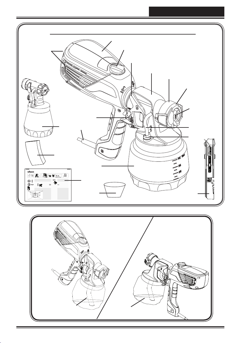
4. Description/ Scope of delivery
Description/ Scope of delivery (Fig. 1)
1) Air cap 2) Nozzle
3) Spray jet adjustment ring 4) Union nut
5) Wall Extra I-Spray spray attachment 6) Trigger
7) Air volume control 8) Spray gun rear part
9) Air lter cover (right + left) 10) Material volume adjustment
11) Mains lead 12) Container
13) Valve 14) Ventilating hose
15) Stirring rod 16) Feed hopper (2 pcs.)
17) Practice poster 18) Replacement air lter (2 pcs.)
19) Standard spray attachment 20) Replacement nozzle seal*
21) Lubricating grease*
* This is inside the container: remove it before starting operations!
5. Field of application
Many dierent coating substances can be processed with the W 570.
A dierent spray attachment must be used, depending on the coating substance:
Coating Materials Spray attachment
Low-viscosity coating substances:
Water- and solvent-based paints, nishes,
primers, 2-component paints, clear
nishes, automotive nishes, staining
sealers and wood sealer-preservatives.
All coating materials with the red Perfect
Spray logo
Standard
GB
Interior wall paint (dispersions and latex
paint)
All coating materials with the green
Perfect Spray logo
Wall Extra I-Spray
6. Coating Materials Suitable for Use
Interior wall paint (dispersions and latex paint)
Water- and solvent-based paints, nishes, primers, 2-component paints, clear nishes,
automotive nishes, staining sealers and wood sealer-preservatives.
25
Page 15

GB
W 570 Flexio
7. Coating Materials Not Suitable for Use
Materials that contain highly abrasive components, plaster, facade paint, caustic solutions
and acidic coating substances. Flammable materials.
8. Preparation of the workplace (for interior wall paint)
Sockets and plugs must be masked. Risk of an electric shock as a
consequence of sprayed material entering the socket!
Mask all the areas and objects that are not to be spray painted, or
remove them from the work area. No liability is assumed for damage
due to overspray. Silicate paint corrodes glass and ceramic surfaces
upon contact! All such surfaces must therefore be completely covered.
Pay attention to the quality of the adhesive tape used.
Do not use excessively strong adhesive tape on wallpaper and painted
i
surfaces, in order to avoid damaging these surfaces when removing the
tape. Remove adhesive tape slowly and evenly; do not use jerky movements.
Do not leave adhesive tape on surfaces any longer than necessary, in order
to minimise the possibility of residues when removing.
Also observe the adhesive tape manufacturer's instructions.
9. Preparation of the Coating Material
Mix the material well in the original container. When using interior wall paint, an
•
agitator is recommended.
W 570 has been developed for use with all conventional paints in their undiluted
i
form. If the surface is smooth and the paint you are using is very thick and
gel-like, dilute it by 10%. Dilution can be necessary if the atomisation is
coarse or if the ow rate is too low even at the maximum setting.
Detailed information about the various materials and the maximum permitted
dilution can be found on the manufacturers' technical data sheets (e.g. available
on the Internet).
Spray material that is at least at room temperature provides a better spray
i
result.
26
Page 16

W 570 Flexio
GB
10. Start-up
Before connecting to the mains supply, be sure that the supply voltage is identical with
the value given on the rating plate.
Unscrew the container from the spray gun.
•
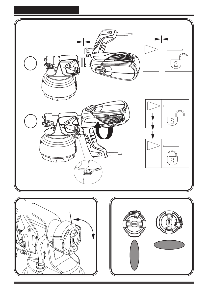
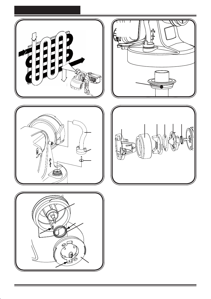
Aligning suction tube. (Fig. 2)
•
If the suction tube is positioned correctly, the container contents can be sprayed without
almost any residue.
When working on lying objects: Turn the suction tube forwards. (Fig. 2 A)
Spraying work when working on overhead objects: Turn the suction tube rearwards.
(Fig. 2 B)
Place the container on a paper base and pour in the prepared coating substance with the
•
aid of the feed hopper included in the scope of supply (Fig. 1, 16). Screw the container
tightly onto the spray gun.
Connect the front part with the rear part of the gun (Fig. 3).
•
Put the machine down only on a level, clean surface. Otherwise the machine could tip
•
over!
Pull the trigger. The W 570 has a two-stage trigger. In the rst stage the turbine is started.
•
If the trigger guard is pressed further, the material is transported.
Adjust the spray setting on the spray gun.
•
The enclosed practice poster is ideal for familiarising yourself with
operation of the spray gun. After trying out the rst spray coatings, it
i
makes sense to test it further on cardboard or a similar surface in order
to nd out the right ow rate of paint and air for the best spray pattern.
Detailed information about these settings can be found in chapter 11-14.
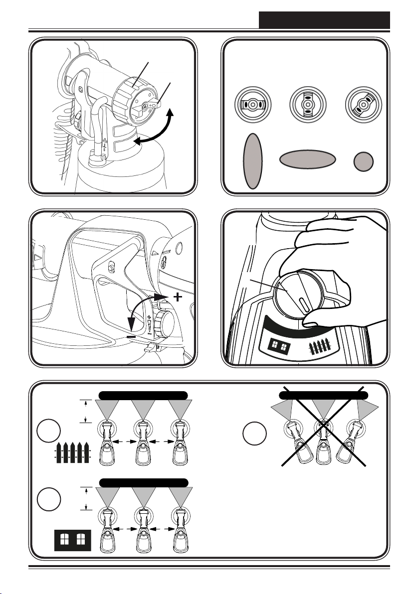
11. Selecting the Spray Setting
(Wall Extra I-Spray spray attachment)
WARNING! Danger of injury! Never pull the trigger guard while adjusting
the air cap.
2 dierent spray jet shapes can be set by turning the adjustment ring (g. 4, 1)
Fig. 5 A = vertical at jet
Fig. 5 B = horizontal at jet
Use the red adjustment lever to also switch between a wide (
and a narrow ( ) spray jet.
for horizontal surfaces
for vertical surfaces
)
27
Page 17

GB
W 570 Flexio
12. Selecting the Spray Setting
(Standard spray attachment)
WARNING! Danger of injury! Never pull the trigger guard while adjusting
the air cap.
With the union nut (g. 6, 1) slightly unscrewed, turn the air cap (2) to the desired
spraysetting position (arrow). Then tighten the union nut.
Fig. 7 A = vertical at jet
Fig. 7 B = horizontal at jet
Fig. 7 C = circular jet
for horizontal surfaces
for vertical surfaces
for corners, edges and hard-to-reach surfaces
13. Adjusting the Material Volume (Fig. 8)
Set the material volume by turning the regulator on the trigger guard of the spray gun.
lower material volume turn anti-clockwise (-)
higher material volume turn clockwise (+)
14. Setting the Amount of Air (Fig. 9)
Depending on the viscosity of the material to be sprayed and the nish of
i
the object to be coated, it may be advisable to vary the amount of air. Very
low viscosity materials, such as watery glazes do not have to be atomised
with the maximum amount of air. In this case it is advisable to reduce
the amount of air and thus minimize the spray vapour.
This also applies for the use of the Detail and Corner&Reach spray attachment
(accessory).
Turn the air quantity regulator (g. 9.1) to the required position.
thin paint
thick paint (e.g. interior wall paint)
Wood & Metal
Wall & Ceiling
28
Page 18

W 570 Flexio
GB
15. Spray Technique
The spray result depends heavily on the smoothness and cleanliness of the
i
surface to be sprayed. Therefore the surface should be carefully prepared and
kept free of dust.
Cover all surfaces not to be sprayed.
•
Cover screw threads or similar parts of the target object.
•
Important: Start at the edge of the area to be sprayed. Start the spray
movement rst of all, and then press the trigger. Avoid interruptions
i
within the area to be sprayed.
The spray movement should come from the arm, not just from the wrist. This ensures that
•
a uniform distance is maintained between the spray gun and the spray surface during
the spray operation. Select a distance of 5 - 15 cm, depending on the desired spray jet
width. When you are using interior wall paint, the distance should be about 20-30 cm.
Fig. 10 A/ 10 B: CORRECT Even distance to the object.
Fig. 10 B:
Move the spray gun evenly cross-wise or up-and-down, depending on the spray
•
pattern setting.
An even movement of the spray gun results in an even surface quality.
•
Important: Wipe o the nozzle and air cap regularly
to make sure they do not get blocked.
i
INCORRECT An uneven distance will result in uneven paint
application.
"Cross spray" when using paint with a poor covering capacity or if the
surface is highly absorbent (Fig. 11).
i
Interior wall paint in strong colour shades should be applied at least twice (allow rst
•
paint coat to dry rst). This will ensure good coverage.
16. Interruption of Work
Turn the machine o.
•
During longer breaks, vent the container by briey opening and then closing it again.
•
Clean nozzle openings after an interruption in operation.
•
When processing 2-component varnishes, clean the device immediately.
•
29
Page 19

GB
W 570 Flexio
17. Taking Out of Operation and Cleaning
Proper cleaning is the prerequisite for problem-free operation of the paint application
device. No warranty claims are accepted in case of improper or no cleaning.
Never hold the spray gun rear part under water or immerse it into liquids.
Clean the housing only with a moistened cloth.
1)
Unplug the power plug. Vent the container in case of longer breaks and after the work
has been terminated. This can be done by briey turning open and then closing the
container or by pulling the trigger guard and letting the paint into the original paint
container.
2)
Divide the spray gun. Press the hook (Fig. 3 b "click") slightly downwards. Turn the gun
front part and gun rear part against each other and take them apart.
3) Unscrew the container. Empty any remaining coating material back into the material
tin.
4)
Preclean the container and feed tube with a brush. Clean the ventilating bore
(Fig. 12, 1).
5)
Pour water or solvent into the container. Screw the container back on.
Do not use ammable materials for cleaning purposes.
6) Assemble the gun again (Fig. 3).
7)
Insert the power plug, turn on the machine and spray the water or solvent into a
container or a cloth.
8) Repeat the above procedure until the water or solvent emerging from the nozzle is
clear.
9) Turn o the machine and remove the plug.
10)
Divide the spray gun. Press the hook (Fig. 3 b "click") slightly downwards. Turn the gun
front part and gun rear part against each other and take them apart.
18. Cleaning the Wall Extra I-Spray
spray attachment
1) Screw of the container and empty it. Pull out the suction tub with container seal.
CAUTION! Never clean seals, diaphragm and nozzle or air holes of the spray gun with metal
objects.
The ventilation hose and diaphragm are only solvent-resistant to a limited
extent. Do not immerse in solvent, only wipe.
2) Pull the ventilating hose (Fig. 13, 1) at the top from the gun body. Screw o the valve
cover (2). Remove the diaphragm (3). Clean all the parts carefully.
3) Remove the adjustment ring (g. 14, 1) carefully from the union nut (2).
4) Unscrew the union nut (g. 14, 2) and remove the air cap (3), air screen (4), and nozzle
(5). Clean the air cap, air screen, nozzle seal (6) and nozzle with a brush and solvent or
water.
30
Page 20

W 570 Flexio
5)
Clean the outside of the spray gun and container with a cloth soaked in solvent or
water.
6) Assemble the parts again (see “Assembly”).
GB
Assembly
The unit may only be operated with an integer diaphragm (Fig. 13, 3).
1) Place the diaphragm (Fig. 13, 3) with the pin facing upwards on the bottom section
of the valve. Also see the marking on the gun body.
2) Place on the valve cover (Fig. 13, 2) and screw it closed.
3) Place the ventilating hose (Fig. 13, 1) on the valve cover and on the nipple at the gun
body.
Attention! Never operate the device if the nozzle seal is either damaged or
missing. If the nozzle seal is either missing or damaged liquids can enter
the device and increase the risk of an electric shock.
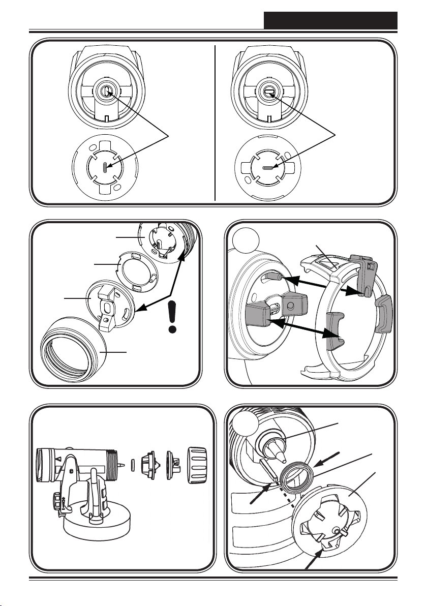
Push the nozzle seal (g. 15, 6) over the needle (7); the groove (slot) should point
4)
towards you.
5)
Place the nozzle (g. 15, 5) on to the gun body with the recess facing downwards.
Attention: Position of needle must be congruent with the nozzle aperture. (Fig.16)
6) Put the air screen (g. 17, 4) in the air cap (3). Put both on the nozzle (5) and secure
with the union nut (2).
7) Adjust the setting ring (g. 18, 1) so that the two "horns" grip the air cap and the red
adjustment lever rests on the pin.
8) Place the container seal from below on the suction tube and slide it over the collar,
while turning the container seal slightly.
9) Insert the suction tube with container seal in the gun body.
19. Cleaning the Standard spray attachment
1) Screw of the container and empty it. Pull out the suction tub with container seal.
CAUTION! Never clean seals, diaphragm and nozzle or air holes of the spray gun with metal
objects.
The ventilation hose and diaphragm are only solvent-resistant to a limited
extent. Do not immerse in solvent, only wipe.
2) Pull the ventilating hose (Fig.13, 1) at the top from the gun body. Screw o the valve
cover (2). Remove the diaphragm (3). Clean all the parts carefully.
3) Unscrew the union nut and remove the air cap and nozzle. Clean the air cap, nozzle
seal and nozzle with a brush and solvent or water (Fig. 13).
4)
Clean the outside of the spray gun and container with a cloth soaked in solvent or
water.
5) Assemble the parts again (see “Assembly”).
31
Page 21

GB
W 570 Flexio
Assembly
The unit may only be operated with an integer diaphragm (Fig. 13, 3).
1) Place the diaphragm (Fig. 13 ,3) with the pin facing upwards on the bottom section
of the valve. Also see the marking on the gun body.
2) Place on the valve cover (Fig. 13 ,2) and screw it closed.
3) Place the ventilating hose (Fig. 13, 1) on the valve cover and on the nipple at the gun
body.
Attention! Never operate the device if the nozzle seal is either damaged or
missing. If the nozzle seal is either missing or damaged liquids can enter
the device and increase the risk of an electric shock.
Push the nozzle seal (g. 20, 1) over the needle (3); the groove (slot) should point
4)
towards you.
5) Put the nozzle (g. 20, 2) onto the gun body and nd the correct position by turning it.
6) Put the air cap onto the nozzle and tighten it using the union nut.
7) Place the container seal from below on the suction tube and slide it over the collar,
while turning the container seal slightly.
8) Insert the suction tube with container seal in the gun body.
20. Maintenance
WARNING! Never operate the machine without the air filter;
dirt could be sucked in and interfere with the function of the
machine. Check the air filter after each use for contaminants.
Disconnect plug before changing parts.
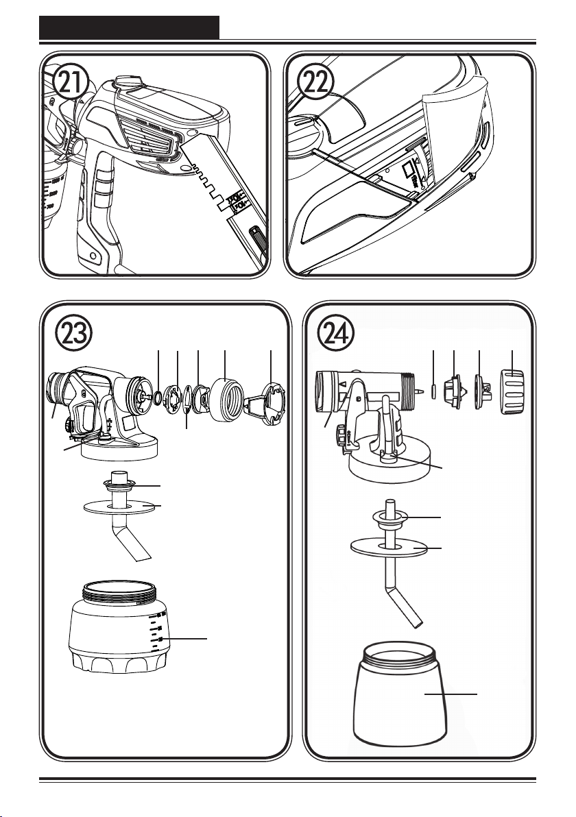
1) Open the air lter lid with the help of the stirring rod. (Fig. 21)
2) Pull out the air lter and replace it if necessary, depending on how soiled it is.
3) First, push the new air lter into the bottom part of the compartment. (Fig. 22)
Next push it completely into the compartment.
4)
In order to push the air lter into the compartment completely, we recommend using
the stirring rod.
In order to mount the gun more easily apply lubricating grease (enclosed) liberally
to the O-ring at the gun front part. (Fig. 23, 6 and g. 24,5)
32
Page 22

W 570 Flexio
21. Spare Parts
Spare Parts List Wall Extra I-Spray spray attachment (Fig. 23)
Pos. Designation Order No.
Wall Extra I-Spray spray attachment complete with 1300 ml
container
1 Spray jet adjustment ring 2353 697
2 Union nut 2353 698
3 Air cap 2363 208
4 Air screen 2362 886
5 Nozzle 2328 908
6 Nozzle seal (2 pcs.) 2304 433
7 O-ring of spray attachment 2362 875
8 Ventilating hose, valve cover, diaphragm 2304 027
9 Suction tube 2328 922
10 Container seal 2328 919
11 Container with cover 1300 ml (only for Wall Extra I-Spray spray
attachment)
Spare Parts List Standard spray attachment (Fig. 24)
Pos. Designation Order No.
Standard spray attachment complete with 800 ml container 2361 730
1 Union nut 2362 873
2 Air cap 2362 877
3 Nozzle 2362 878
4 Nozzle seal 0417 706
5 O-ring of spray attachment 2362 875
6 Ventilating hose, valve cover, diaphragm 2304 027
7 Suction tube 2362 876
8 Container seal 2323 039
9 Container with cover 800 ml 0413 909
2361 746
2305 155
AUS 2361 731
AUS 2361 747
GB
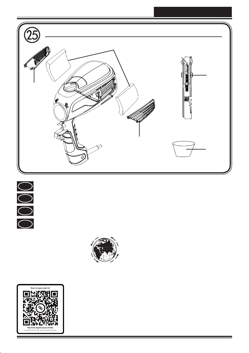
Spare Parts List W 570 (Fig. 25)
Pos. Benennung Best. Nr.
1 Air lter cover (right + left) 2335 172
2 Air lter set (2 pcs.) 2333 123
3 Stirring rod 2304 419
4 Feed hopper (3 pcs.) 2304 028
Lubricating grease (no g.) 2315 539
33
Page 23

GB
W 570 Flexio
22. Accessories
The CLICK&PAINT SYSTEM with additional spray attachments and accessories oers
the right tool for each work.
Further information about the WAGNER range of products for renovating is available
under www.wagner-group.com
23. Correction of Malfunctions
Problem Cause Remedy
No coating material
emerges from the
nozzle
Coating material
drips from the
nozzle
Atomisation too
coarse
Nozzle clogged
•
Feed tube clogged
•
Material volume setting turned
•
too far to the left (-)
Feed tube loose
•
No pressure build-up in container
•
Ventilating bore (Fig. 12,1)
•
clogged
Nozzle loose
•
Nozzle worn
•
Nozzle seal is missing or worn
•
Coating material assembly at air
•
cap, nozzle or needle
Coating material too thick
•
Material volume too large
•
Material volume adjusting screw
turned too far to the right (+)
Nozzle contaminated
•
Air lter heavily soiled
•
Too little pressure build-up in
•
container
Amount of air too low
•
➞ Clean
➞ Clean
➞ Turn to the right (+)
➞ Insert
➞ Tighten container
➞ Clean
➞ Tighten
➞ Change
➞ Insert an intact nozzle
seal
➞ Clean
➞ Dilute
➞ Turn material volume
adjusting screw to the
left (-)
➞ Clean
➞ Change
➞ Tighten container
➞ Increase air quantity
(Level: Wall & Ceiling
)
Spray jet pulsates
34
Coating material in container
•
running out
Air lter heavily soiled
•
Nozzle seal is missing or worn
•
➞ Rell
➞ Change
➞ Insert an intact nozzle
seal
Page 24

W 570 Flexio
Problem Cause Remedy
Coating material
causes "paint tears"
Too much fog of
coating material
(Overspray)
Too much coating material
•
applied.
Distance to the object too large
•
Too much coating material
•
applied
Amount of air too high
•
➞ Turn material volume
adjusting screw to the
left (-)
➞ Reduce distance
➞ Turn material volume
adjusting screw to the
left (-)
➞ Decrease air quantity
(Level: Wood & Metal
)
GB
Width of paint spray
cannot be adjusted
Paint in the
ventilating hose
Poor covering
capacity on the wall
Adjustment ring is not connected
•
to the peg on the air cap
Air screen is clogged up
•
Diaphragm soiled
•
Diaphragm defective
•
Spray material is too cold
•
Highly absorbent surface or paint
•
with poor covering capacity
Distance too large
•
➞ Connect adjustment
ring and peg
➞ Disassemble and clean
➞ Clean the diaphragm
➞ Replace the diaphragm
➞ The material you are
spraying should be at
room temperature
➞ Cross spray (Fig. 11)
➞ Closer to the object
24. Technical Data
Technical Data
Max. viscosity (Interior wall paint/Wall Extra
I-Spray spray attachment):
Power source: 230 V
Power consumption: 630 W / 660 W
Atomizing output: 100 W (min), 200 W (max)
Max. ow rate (Interior wall paint/Wall Extra
I-Spray spray attachment):
Protection Class: I
Sound pressure level*: 74 dB (A); Uncertainty K = 4 dB
Sound pressure output*: 87 dB (A); Uncertainty K = 4 dB
Oscillation level*: < 2.5 m/s²; Uncertainty K = 1.5 m/s²
Weight: 1.9 kg
4000 mPas
~
, 50 Hz / 240 V ~, 50 Hz
500 ml/min
* Measured in accordance with EN 60745-1
35
Page 25

GB
W 570 Flexio
Information about the oscillation level
The specied oscillation level has been measured according to a standard test
procedure and can be used to compare against electric tools.
The oscillation level is also for determining an initial assessment of the vibrational
strain.
Attention! The vibration emission value can dier from the specied value when the
electric tool is actually in use, depending on how the electric tool is being used. It is
necessary to specify safety measures to protect the operating personnel. These measures
are based on an estimated shutdown during the actual conditions of use (all parts of the
operating cycle are taken into consideration here, for example periods when the electric
tool is switched o, and, when it is switched on but running without any load).
25. Environmental protection
The device and all accessories and packaging have to be recycled in an
environmentally friendly manner. Do not dispose of the appliance with
household waste. Support environmental protection by taking the appliance
to a local collection point or obtain information from a specialist retailer.
Leftover paint and solvents may not be emptied into drains, the sewage system
or disposed of as household rubbish. It has to be disposed of separately as
special waste. Please pay special attention to the instructions on the product
packaging.
26. Important Note regarding Product Liability!
According to an EU directive, the manufacturer is only liable without limitation for faults
in the product if all parts come from the manufacturer or have been approved by the
manufacturer and have been mounted to the device and are operated properly. If thirdparty accessories or spare parts are used, the manufacturer is exonerated wholly or partly
from his/her liability if use of the third-party accessories or spare parts have caused a
defect in the product.
36
Page 26

W 570 Flexio
GB
3+1 years guarantee
The guarantee runs for three years, counting from the date of sale (sales slip). The
guarantee is extended by a further 12 months if the device is registered online within
4 weeks of the purchase at www.wagner-group.com/3plus1. Registration is only
possible if the buyer is in agreement with the data being stored that is entered during
registration. The guarantee covers and is restricted to free-of-charge rectication
of faults which are demonstrably attributable to the use of faulty materials in
manufacture, or assembly errors; or free-of-charge replacement of the defective parts.
The guarantee does not cover incorrect use or commissioning or tting or repair work
which is not stated in our operating instructions. Wearing parts are also excluded from
the guarantee. The guarantee excludes commercial use. We expressly reserve the right
to full the guarantee. The guarantee expires if the tool is opened up by persons other
than WAGNER service personnel. Transport damage, maintenance work and loss and
damage due to faulty maintenance work are not covered by the guarantee. Under
any guarantee claim, there must be proof of purchase of the tool through submission
of the original receipt. Wherever legally possible, we exclude all liability for injury,
damage or consequential loss, especially if the tool has been used for a purpose other
than that stated in the operating instructions, commissioned or repaired other than
in accordance with our operating instructions or if repairs are performed by someone
who is unqualied. We reserve the right to perform any repairs in excess of those
stated in our operating instructions. In case of guarantee or repair, please refer to your
point of sale.
37
Page 27

GB
Warning
If the supply cord of this appliance is
damaged, it must only be replaced by a
repair shop appointed by the manufacturer,
because special purpose tools are required.
The wires in this mains lead are coloured in
accordance with the following code:
green/yellow = earth
blue = neutral brown = live
As the colours of the wires in the mains
lead of this appliance may not correspond
with the coloured markings identiying the
terminals in your plug, proceed as follows:
The wire which is coloured green and yellow must be connected to the terminal in
•
the plug which is marked with the letter E or by the earth symbol or coloured green or
green and yellow.
The wire which is coloured blue must be connected to the terminal which is marked
•
with the letter N or coloured black.
The wire which is coloured brown must be connected to the terminal which is marked
•
with the letter L or coloured brown.
Should the moulded plug have to be replaced, never re-use the defective plug or
•
attempt to plug it into a dierent 13 A socket. This could result in an electric shock.
Should it be necessary to exchange the fuse in the plug only use fuses approved by
•
ASTA in accordance with BS 1362. Only 13 Amp fuses may be used.
To ensure that the fuse and fuse carrier are correctly mounted please observe the
•
provided markings or colour coding in the plug.
After changing the fuse, always make sure that the fuse carrier is correctly inserted.
•
Without the fuse carrier, it is not permissible to use the plug.
The correct fuses and fuse carriers are available from your local electrical supplies
•
stockist.
W 570 Flexio
38
Page 28

W 570 Flexio
D
CE Konformitätserklärung
Wir erklären in alleiniger Verantwortung, dass dieses Produkt den folgenden einschlägigen Bestimmungen entspricht:
2006/42/EG, 2014/30/EU, 2011/65/EU, 2012/19/EU
Angewandte harmonisierte Normen:
EN 60745-1:2009+A11:2010, EN 50580:2012+A1:2013, EN 62233:2008,
EN 55014-1:2006+A1:2009+A2:2011, EN 55014-2:1997+Corrigendum 1997+A1:2001
+A2:2008, EN 61000-3-2:2014, EN 61000-3-3:2013
CE Declaration of Conformity
GB
We declare under sole responsibility that this product conforms to the following
relevant stipulations:
2006/42/EC, 2014/30/EU, 2011/65/EU, 2012/19/EU
Applied harmonised norms:
EN 60745-1:2009+A11:2010, EN 50580:2012+A1:2013, EN 62233:2008,
EN 55014-1:2006+A1:2009+A2:2011, EN 55014-2:1997+Corrigendum 1997+A1:2001
+A2:2008, EN 61000-3-2:2014, EN 61000-3-3:2013
CE Déclaration de conformité
F
Nous déclarons sous notre responsabilité que ce produit est en conformité avec les
réglementations suivantes:
2006/42/CE, 2014/30/UE, 2011/65/UE, 2012/19/UE
Conforme aux normes et documents normalisés:
EN 60745-1:2009+A11:2010, EN 50580:2012+A1:2013, EN 62233:2008,
EN 55014-1:2006+A1:2009+A2:2011, EN 55014-2:1997+Corrigendum 1997+A1:2001
+A2:2008, EN 61000-3-2:2014, EN 61000-3-3:2013
NL
Wij verklaren dat dit product voldoet aan de volgende normen:
2006/42/EG, 2014/30/EU, 2011/65/EU, 2012/19/EU
En normatieve dokumenten:
EN 60745-1:2009+A11:2010, EN 50580:2012+A1:2013, EN 62233:2008,
EN 55014-1:2006+A1:2009+A2:2011, EN 55014-2:1997+Corrigendum 1997+A1:2001
+A2:2008, EN 61000-3-2:2014, EN 61000-3-3:2013
i.V. T. Jeltsch i. V. J. Ulbrich
Senior Vice President Vice President Engineering
Global Product Strategy & Planning
Dokumentationsverantwortlicher
Responsible person for documents
Responsable de la documentation
Documentatieverantwoordelijke
CE Conformiteitsverklaring
NL
J. Wagner GmbH Otto-Lilienthal-Str. 18 D-88677 Markdorf
77
Page 29

D
EL-ME-HO
Horvatinčićev put 2
HR-10436 Rakov Potok
T +385 (-1)65 86 - 028
F +385 (-1)65 86 - 028
HR
OOO МЕФФЕРТ ПОЛИЛЮКС
142407 , ,
-,
«-» .14
T +7 495 221 6666
F +7 495 99 55 88 2
RUS
ROMIB S.R.L.
str. Poligonului nr. 5 - 7
ROM-100070 Ploiesti ,judet Prahova
T +40-344801240
F +40-344801239
ROM
TEHOMIX OY
Telekatu 10
SF-20360 TURKU
T +385 (0) 2 2755 999
F +385 (0) 2 2755 995
SF
F 0373 204845
J. WAGNER GMBH
Otto-Lilienthal-Str. 18
D-88677 Markdorf
T +49 0180 - 55 92 46 37
F +49 075 44 -5 05 11 69
SK
E-CORECO SK S.R.O.
Kráľovská ulica 8/7133
SK-927 01 Šaľa
T +42 1948882850
F +42 1313700077
SLO
GMA ELEKTROMEHANIKA
D.O.O.
Cesta Andreja Bitenca 115,
SLO-Ljubljana 1000
T +386(1) 583 83 04
F +386(1) 518 38 03
F
WAGNER FRANCE S.A.R.L.
12 Avenue des Tropiques
Z.A. de Courtaboeuf
F-91978 Les Ulis Cedex
T +33 0825 011 111
F +33 (0) 1 69 81 72 57
DK
WAGNER SPRAYTECH
Scandinavia A/S
S
Helgeshøj Allé 28
DK-2630 Tåstrup
T +45 43 27 18 18
F +45 43 43 05 28
SF
TEHOMIX OY
Telekatu 10
SF-20360 TURKU
T +385 (0) 2 2755 999
F +385 (0) 2 2755 995
E
MAKIMPORT
HERRAMIENTAS, S.L.
P
C/ Méjico nº 6
Pol. El Descubrimiento
E-28806 Alcalá de Henares
(Madrid)
T 902 199 021 / 91 879 72 00
F 91 883 19 59
GB
WAGNER SPRAYTECH (UK) LTD
Opus Park
Moorfield Road
GB-Guildford Surrey GU1 1SZ
T +44 (0) 1483 - 454666
F + 44 (0) 1483 - 454548
CZ
E-CORECO S.R.O.
Na Roudné 102
CZ-301 00 Plzeň
T +42 734 792 823
F +42 227 077 364
ROM
ROMIB S.R.L.
str. Poligonului nr. 5 - 7
ROM-100070 Ploiesti ,judet Prahova
T +40-344801240
F +40-344801239
AUS
WAGNER SPRAYTECH
AUSTRALIA PTY. LTD.,
14 -16 Kevlar Close
AUS-Braeside, VIC 3195
T +61 3 95 87 - 20 00
F +61 3 95 80 - 91 20
H
HONDIMPEX KFT.
Kossuth L. u. 48-50
H-8060 Mór
T +36 (-22) - 407 321
F +36 (- 22) - 407 852
PL
PUT WAGNER SERVICE
ul. E. Imieli 27
PL-41-605 Swietochlowice
T +48 32 - 346 37 10
F +48 32 - 346 37 13
CH
J. WAGNER AG
Industriestraße 22
CH-9450 Altstätten
T +41 71 - 7 57 22 11
F +41 71 - 7 57 23 23
I
FHC SRL
Via Stazione 94,
I-26013 Crema (CR)
T 0373 204839
Irrtümer und Änderungen vorbehalten.
Not responsible for errors and changes.
Sous réserves d’erreurs et de modifications.
Fouten en wijzigingen voorbehouden.
Part. No. 2361814
09/2015_RS
© Copyright by J.Wagner GmbH
 Loading...