

Page 1

VM 5000
B_03269
c
us
Electrostatic Control Unit
for Electrostatic Manual Spray Guns
Version 07/2014
Translation of the Original
Operating Manual
Page 2

Page 3

3
VM 5000
OPERATING MANUAL
EDITION 07/2014 ORDER NUMBER DOC 2344501
Contents
1 ABOUT THIS OPERATING MANUAL 5
1.1 Preface 5
1.2 Warnings, Notices, and Symbols in this Operating Manual 5
1.3 Languages 6
1.4 Abbreviations in the Text 6
2 CORRECT USE 7
2.1 Device Type 7
2.2 Type of Use 7
2.3 Safety Parameters 7
2.4 Reasonably Foreseeable Misuse 8
2.5 Residual Risks 8
3 IDENTIFICATION 9
3.1 Explosion Protection According to FM 9
3.2 Permissible Device Combinations 9
3.3 Notes to German Regulations and Guidelines 9
4 GENERAL SAFETY INSTRUCTIONS 10
4.1 Safety Instructions for the Operator 10
4.1.1 Electrical Equipment 10
4.1.2 Sta Quali cations 10
4.1.3 Safe Work Environment 11
4.2 Safety Instructions for Sta 11
4.2.1 Safe Handling of WAGNER Spray Devices 12
4.2.2 Grounding the Device 12
4.2.3 Material Hoses 13
4.2.4 Cleaning 13
4.2.5 Handling Hazardous Liquids, Lacquers and Paints 14
4.2.6 Touching Hot Surfaces 14
4.3 Correct Use 14
4.4 Safety Information on Discharges 15
4.5 Protective and Monitoring Equipment 15
5 DESCRIPTION 16
5.1 Areas of Application 16
5.2 Functional Description 16
5.3 Technical Data 16
5.4 Scope of Delivery 17
5.5 Operating Elements and Connections 18
5.5.1 Operating Elements Front Side 18
5.5.2 Connections on the Rear Side 20
6 COMMISSIONING AND OPERATION 21
6.1 Training Assembly/Commissioning Sta 21
6.2 Storage Conditions 21
6.3 Installation Conditions 21
6.4 Additional Components 22
6.5 Placement of the Device 23
6.6 Grounding 24
6.7 Example: AirCoat Spraying System 26
Page 4

4
VM 5000
OPERATING MANUAL
EDITION 07/2014 ORDER NUMBER DOC 2344501
Table of Contents
6.8 Device Con guration 28
6.8.1 Parameter Overview of Level 1 for Users 28
6.8.2 Access to the Device Con guration Mode 30
6.8.3 Setting Example "Parameter C11" 31
6.9 Operating Hours Counter / Service Display 33
6.9.1 Maintenance Counter Set Up and Reading 34
6.10 External Interface 35
7 OPERATION 37
7.1 Training the Operating Sta 37
7.2 Safety Instructions 37
7.3 Control Unit Start Up 38
7.4 Setting and Saving Recipes 39
7.4.1 Setting the High-voltage 40
7.4.2 Setting the Current Limiting 41
7.4.3 Display During Spraying 42
7.5 Standby Mode 43
7.6 Display "Conduct Service" 44
8 TROUBLESHOOTING AND RECTIFICATION 45
9 MAINTENANCE AND REPAIR 47
9.1 Maintenance 47
9.2 Repair 47
10 PRODUCT DISPOSAL 47
11 ACCESSORIES 48
12 SPARE PARTS 49
12.1 How Can Spare Parts Be Ordered? 49
12.2 Spare Parts List VM 5000 50
13 WARRANTY 52
13.1 Important Notes Regarding Product Liability 52
13.2 Warranty Claim 52
Page 5

5
VM 5000
OPERATING MANUAL
EDITION 07/2014 ORDER NUMBER DOC 2344501
1.2 WARNINGS, NOTICES, AND SYMBOLS IN THIS OPERATING MANUAL
1 ABOUT THIS OPERATING MANUAL
The operating manual contains information about safely operating, maintaining, cleaning
and repairing the device.
The operating manual is part of the device and must be available to operating and service sta .
Operating and service sta should be instructed according to the safety instructions.
The device may only be operated in compliance with this operating manual.
This equipment can be dangerous if it is not operated according to the instructions in this
operating manual.
1.1 PREFACE
Warning instructions in this operating manual highlight particular dangers to users and
to the device and state measures for avoiding the hazard. These warning instructions fall
into the following categories:
Danger - immediate risk of danger.
Non-observance will result in death or serious injury.
Warning - possible imminent danger.
Non-observance may result in death or serious injury.
Caution - a possibly hazardous situation.
Non-observance may result in minor injury.
Notice - a possibly hazardous situation.
Non-observance may result in material damage.
Note - provides information about particular characteristics and how to proceed.
This notice warns you of a hazard!
Possible consequences of not observing the warning instructions.
The signal word indicates the hazard level.
The following are measures which can be taken to prevent
the hazard and its consequences.
DANGER
This notice warns you of a hazard!
Possible consequences of not observing the warning instructions.
The signal word indicates the hazard level.
The following are measures which can be taken to prevent
the hazard and its consequences.
WARNING
This notice warns you of a hazard!
Possible consequences of not observing the warning instructions.
The signal word indicates the hazard level.
The following are measures which can be taken to prevent
the hazard and its consequences.
CAUTION
This notice warns you of a hazard!
Possible consequences of not observing the warning instructions. The signal word
indicates the hazard level.
The following are measures which can be taken to prevent the hazard and its
consequences.
NOTICE
Page 6

6
VM 5000
OPERATING MANUAL
EDITION 07/2014 ORDER NUMBER DOC 2344501
1.3 LANGUAGES
1.4 ABBREVIATIONS IN THE TEXT
Number of pieces
Position
Marking in the spare parts lists
Order No. Order number
Spare part
Stainless steel
Two components
The operating manual is available in the following languages:
German English 2344501
Page 7

7
VM 5000
OPERATING MANUAL
EDITION 07/2014 ORDER NUMBER DOC 2344501
2 CORRECT USE
2.1 DEVICE TYPE
2.2 TYPE OF USE
WAGNER's electrostatic control unit VM 5000 controls and regulates the high-voltage
supply to the GM 5000EA or GM 5000EAC spray guns used to apply liquid coating media
and the high-voltage Universal cascade.
The VM 5000 may only be operated together with the above-mentioned manual spray
guns or the high-voltage Universal cascade. If the control unit is operated in combination
with devices other than the above-mentioned spray guns, the FM authorizations (type
approvals) cease to be valid.
These electrostatic manual spray guns are suitable for spraying liquid products, in particular
coating products that follow AirCoat or Airspray techniques. Coating products containing
solvents of explosion class II A may be used.
Control unit for controlling GM 5000EA or GM 5000EAC electrostatic spray guns and the
high-voltage Universal cascade.
Incorrect use!
Risk of injury and equipment damage.
Only connect original Wagner spray guns or the high-voltage
Universal cascade to the VM 5000 control unit.
Only connect the GM 5000EA, GM 5000EAC spray guns or the
high-voltage Universal cascade.
WARNING
2.3 SAFETY PARAMETERS
The control unit is only suitable for controlling spray guns and the Wagner high-voltage
Universal cascade. J. Wagner AG forbids any other use!
The control unit may only be operated under the following conditions:
The operating sta have previously been trained on the basis of this operating manual.
The safety regulations listed in this operating manual must be observed.
The operating, maintenance, and repair information in this operating manual must be
observed.
The statutory requirements and accident prevention regulation standards in the country of use
must be observed.
The control unit may only be operated if all parameters are set and all measurements / safety
checks are carried out correctly.
Page 8

8
VM 5000
OPERATING MANUAL
EDITION 07/2014 ORDER NUMBER DOC 2344501
2.4 REASONABLY FORESEEABLE MISUSE
Coating work pieces which are not grounded
Use of defective components, spare parts or accessories
Use with non-authorized spray guns
2.5 RESIDUAL RISKS
Residual risks are risks which cannot be excluded even in the event of correct use.
If necessary, warning and prohibition signs at the relevant points of risk indicate residual
risks.
Residual risk Source Consequences Speci c measures Lifecycle phase
Skin contact with
solvent-based
paints and cleaning
agents
Handling of solventbased paints and
cleaning agents
Skin irritations, Wear protective
clothing,
Operation,
allergies observe safety data
sheets
maintenance,
disassembly
Solvent-based paint
in air outside the
de ned working
area
Painting outside the
de ned working
area
Inhalation of
substances
hazardous to health
Observe work and
operation instructions
Operation,
maintenance
Page 9

9
VM 5000
C
US
OPERATING MANUAL
EDITION 07/2014 ORDER NUMBER DOC 2344501
The following spray guns may be connected to the VM 5000 control unit:
GM 5000EA spray gun
GM 5000EAC spray gun
Other gun types may only be connected to the control unit after rst checking their suitability
with Wagner.
3.2 PERMISSIBLE DEVICE COMBINATIONS
3.3 NOTES TO GERMAN REGULATIONS AND GUIDELINES
3.1 EXPLOSION PROTECTION ACCORDING TO FM
This device has been manufactured and tested by FM, according to the FM (Factory Mutual)
standard "Class Number 7260" (Approval Standard for Electrostatic Finishing Equipment).
All tested combinations of devices including accessories are given in the FM Control
Document with part number 2316160.
Authorization (type approval) of FM for class 1, div. 1 (spray gun)
For Electrostatic Finishing Applications using Class I, Group D,
Spray Material
In accordance with 2316160
Electrical devices and equipment
Part 2, Chapter 2.36 Working with Liquid Ejection Devices
Part 2, Chapter 2.29 Working with Coating Products
Explosion protection rules
Avoiding ignition risks
Equipment for cleaning work pieces with solvents
Guidelines for liquid ejection devices
Painting rooms and equipment
Electrostatic coating
Plant Safety Ordinance
Note: All titles can be ordered from Heymanns Publishing House in Cologne,
or they can be found on the Internet.
3 IDENTIFICATION
Page 10

10
VM 5000
OPERATING MANUAL
EDITION 07/2014 ORDER NUMBER DOC 2344501
4 GENERAL SAFETY INSTRUCTIONS
4.1 SAFETY INSTRUCTIONS FOR THE OPERATOR
4.1.1 ELECTRICAL EQUIPMENT
4.1.2 STAFF QUALIFICATIONS
Keep this operating manual at hand near the device at all times.
Always follow local regulations concerning occupational safety and accident prevention.
Electrical devices and equipment
To be provided in accordance with the local safety requirements with regard to the
operating mode and ambient in uences.
May only be maintained by skilled electricians or under their supervision.
Must be operated in accordance with the safety regulations and electrotechnical regulations.
Must be repaired immediately in the event of problems.
Must be decommissioned if they pose a hazard.
Must be de-energized before work is commenced on active parts. Inform sta about
planned work. Observe electrical safety regulations.
Control units
Place the control unit outside the spray booth / spray zone.
If possible, place the control unit outside the explosion zone (placement in Ex Zone2 is
permissible).
Protect the control unit from extreme temperature and moisture changes.
Protect the control unit from contamination.
Lay and x the connecting cable correctly.
Ensure that the local mains voltage and tension of the device match.
Ensure that the device is operated and repaired only by trained persons.
Page 11

11
VM 5000
OPERATING MANUAL
EDITION 07/2014 ORDER NUMBER DOC 2344501
4.1.3 SAFE WORK ENVIRONMENT
Ensure that the oor in the working area is static dissipative in accordance with
EN61340-4-1 (resistance must not exceed 100 Mohm).
Ensure that all persons within the working area wear static dissipative shoes. Footwear
must comply with EN 20344. The measured insulation resistance must not exceed
100Mohm.
Ensure that during spraying, persons wear static dissipative gloves. The grounding
takes place via the spray gun handle.
If protective clothing is worn, including gloves, it has to comply with EN 1149-5.
The measured insulation resistance must not exceed 100 Mohm.
Paint mist extraction systems must be tted on site according to local regulations.
Ensure that the following components of a safe working environment are available:
– Product/air hoses adapted to the working pressure.
– Personal safety equipment (breathing and skin protection).
Ensure that there are no ignition sources such as naked ames, sparks, glowing wires,
or hot surfaces in the vicinity. Do not smoke.
4.2 SAFETY INSTRUCTIONS FOR STAFF
Always follow the information in this manual, particularly the general safety instructions
and the warning instructions.
Always follow local regulations concerning occupational safety and accident prevention.
Under no circumstances may people with pacemakers enter the area where the
high-voltage eld between the spray gun and the work piece to be coated builds up!
Control units
When commissioning and for all work, read and follow the operating manual and safety
regulations for the additionally required system components.
Do not open the control unit.
Page 12

12
VM 5000
OPERATING MANUAL
EDITION 07/2014 ORDER NUMBER DOC 2344501
4.2.1 SAFE HANDLING OF WAGNER SPRAY DEVICES
The spray jet is under pressure and can cause dangerous injuries.
Avoid injection of paint or cleaning agents:
Never point the spray gun at people.
Never reach into the spray jet.
Before all work on the device, in the event of work interruptions and functional faults:
– Switch o the energy/compressed air supply.
– Relieve the pressure from the spray gun and device.
– Secure the spray gun against actuation.
– In the event of functional faults: remedy the fault as described in the "Troubleshooting"
chapter.
The liquid ejection devices are to be checked for safe working conditions by an expert
(e.g. Wagner Service Technician) as often as necessary or at least every 12 months,
in accordance with the guidelines for liquid emitters (ZH1/406 and BGR500 Part2
Chapter2.36).
– For shut down devices, the examination can be suspended until the next commissioning.
Carry out the work steps as described in the "Pressure Relief/Work Interruptions" chapter:
– if pressure relief is required.
– if the spraying work is interrupted or stopped.
– before the device is cleaned on the outside, checked, or serviced.
– before the spray nozzle is installed or cleaned.
In the event of skin injuries caused by paint or cleaning agents:
Note down the paint or cleaning agent that you have been using.
Consult a doctor immediately.
Avoid danger of injury through recoil forces:
Ensure that you have rm footing when operating the spray gun.
Only hold the spray gun brie y in a position.
4.2.2 GROUNDING THE DEVICE
Depending on the high-voltage on the spray electrode and the ow speed during spraying,
an electrostatic charge may occur in the device. This may result in the formation of sparks
or ames when discharging.
Ensure that the device is grounded at all times.
Ground the work pieces to be coated.
Ensure that all persons inside the working area are grounded, e.g. that they are wearing
static dissipative shoes.
Wear static dissipative gloves for grounding via the spray gun handle when spraying.
Page 13

13
VM 5000
OPERATING MANUAL
EDITION 07/2014 ORDER NUMBER DOC 2344501
Ensure that the hose material is chemically resistant to the sprayed products.
Ensure that the material hose is suitable for the pressure generated in the device.
Ensure that the following information can be seen on the high-pressure hose:
- Manufacturer
- Permissible operating overpressure
- Date of manufacture
Make sure that the hoses are laid only in suitable places. In no case, should hoses be laid
in the following places:
– in high-trafc areas,
– on sharp edges,
– on moving parts, or
– on hot surfaces
Make sure that the hoses are never used to pull or move the equipment.
The electrical resistance of the complete high-pressure hose must be less than 1 Mohm.
4.2.3 MATERIAL HOSES
4.2.4 CLEANING
De-energize the device electrically.
Disconnect the pneumatic supply line.
Relieve the pressure from the device.
Ensure that the ash point of the cleaning agent is at least 15 K above the ambient
temperature or that cleaning is undertaken at a cleaning station with technical ventilation.
To clean, use cloths and brushes moistened with solvent. Abrasive agents or objects
must not be used. Ensure that the spray gun is not damaged in any way while cleaning.
Parts of the spray gun must not be sprayed with or immersed in cleaning agent.
Preferably, non-combustible cleaning agents should be used.
The choice of the appropriate cleaning agent for cleaning purposes of the spray gun
depends on which parts of the spray gun have to be cleaned and which product has
to be removed. When cleaning the spray gun only use non-polar cleaning agents to
prevent conductive residues on the surface of the spray gun. Should it however, be
necessary to use a polar cleaning agent, all residues of this cleaning agent have to be
removed by using a non-conductive and non-polar cleaning agent, once the cleaning
is nished.
Ensure that no electrical component is cleaned with nor even immersed into solvent.
An explosive gas/air mixture forms in closed tanks.
When cleaning devices with solvents, never spray into a closed tank.
Only use electrically conductive tanks for cleaning liquids.
The tanks must be grounded.
Page 14

14
VM 5000
OPERATING MANUAL
EDITION 07/2014 ORDER NUMBER DOC 2344501
4.2.5 HANDLING HAZARDOUS LIQUIDS, LACQUERS AND PAINTS
When preparing or working with lacquer and when cleaning the device, follow the
working instructions of the manufacturer of the lacquers, solvents and cleaning agents
being used.
Take the speci ed protective measures, in particular wear safety goggles, protective
clothing and gloves, as well as hand protection cream if necessary.
Use a mask or breathing apparatus if necessary.
For su cient health and environmental safety: operate the device in a spray booth or
on a spraying wall with the ventilation (extraction) switched on.
Wear suitable protective clothing when working with hot products.
4.3 CORRECT USE
4.2.6 TOUCHING HOT SURFACES
Only touch hot surfaces if you are wearing protective gloves.
When operating the device with a coating product with a temperature of > 43 °C; 109.4 °F:
- Identify the device with a warning label "Warning - hot surface".
Order No.
9998910 Instruction label
9998911 Protection sticker
Note: Order the two stickers together.
WAGNER accepts no liability for any damage arising from incorrect use.
Use the device only to work with the products recommended by WAGNER.
Only operate the device as a whole.
Do not deactivate safety xtures.
Use only WAGNER original spare parts and accessories.
Page 15

15
VM 5000
OPERATING MANUAL
EDITION 07/2014 ORDER NUMBER DOC 2344501
4.4 SAFETY INFORMATION ON DISCHARGES
The plastic parts of the spray gun are charged electrostatically by the high-voltage eld of
the spray gun. In case of c ontact with plastic parts harmless discharges (brush discharges)
may occur. They are completely non-hazardous for human health.
When keeping a distance of 4 to 10 mm; 0.15 to 0.4 inch between spray gun and object to
be sprayed, the corona discharge at the end of the electrode is visible in the dark.
Surface spraying of the control unit
Never spray device parts using electrostatic equipment (electrostatic spray gun!).
Cleaning the control unit
If there are deposits on the surfaces, the device may form electrostatic charges. Flames or
sparks can form during discharge.
Remove deposits from the surfaces to maintain conductivity.
Only use a damp cloth to clean the device.
4.5 PROTECTIVE AND MONITORING EQUIPMENT
Protective and monitoring equipment!
Risk of injury and equipment damage.
Protective and monitoring equipment must not be removed,
modi ed or rendered unusable.
Regularly check for perfect functioning.
If defects are detected on protective and monitoring equipment,
the system must not be operated until these defects are remedied.
WARNING
Page 16

16
VM 5000
OPERATING MANUAL
EDITION 07/2014 ORDER NUMBER DOC 2344501
5 DESCRIPTION
5.1 AREAS OF APPLICATION
Incorrect use!
Risk of injury and equipment damage.
Only connect original Wagner spray guns or the Wagner
high-voltage Universal cascade to the VM 5000 control unit.
Only connect the GM 5000EA or GM 5000EAC spray guns.
WARNING
The VM 5000 control unit, together with the matching GM 5000EA or GM 5000EAC spray
gun and other components, form an electrostatic hand spray system. The VM 5000 supplies
the control voltage for the spray gun, in which high-voltage is subsequently produced. The
set value for high-voltage and the spray current limiting are adjusted on the control unit
and can be saved in three di erent recipes. The high-voltage supply is switched on and o
with the trigger of the spray gun.
The special linear characteristic for high-voltage ensures that if the spray gun is brought
too close to the work piece (or to earth) the high-voltage is reduced automatically to
prevent an accidental spark discharge.
Additionally, the VM 5000 control unit can be used as a universal high-voltage generator,
in combination with the high-voltage Universal cascade.
In addition, the VM 5000 control unit has a wide range of other functions, such as an
operating hours counter, service interval display, external approval, fault display and an
easy-to-use interface.
5.2 FUNCTIONAL DESCRIPTION
Input voltage 115 VAC – 240 VAC, 50 Hz / 60 Hz
Input power max. 40 W
Input current max. 0.5 A
Output voltage max. 20 Vpp
Output current max. 1.0 A AC
High-voltage limiting 70 kV DC
Spray current limiting 100 μA DC
Polarity for negative high-voltage generators
Protection class IP 54 *
Weight (without cables) 2.3 kg; 5.07 lbs.
Operating temperature range 0 – 40 °C; 32 – 104 °F
5.3 TECHNICAL DATA
Page 17

17
VM 5000
A
B
C
B_03270
EXT
100
80
60
40
20
μA
80
60
40
20
10
kV
R3
R1
R2
VM 5000
OPERATING MANUAL
EDITION 07/2014 ORDER NUMBER DOC 2344501
Dimensions:
VM 5000
mm inch
A 250 9.84
B 180 7.09
C 120 4.72
Quantity Order No. Designation
1 2344480 VM 5000 control unit
The standard equipment includes:
Quantity Order No. Designation
1 264626 Mains cable USA; 2 m; 6.56 ft
1 130215 Grounding cable, 10 m, 32.8 ft
2 9951117 Delay-action fuse 1.0 AT
1 2316160 FM Control Document GM 5000E
1 2344501 VM 5000 operating manual, English
1 see 1.1 Operating manual in local language
The delivery note shows the exact scope of delivery.
5.4 SCOPE OF DELIVERY
* Splash water protection is only guaranteed when the gun cable socket is screwed to
the device plug and the mains cable plug is xed to the control unit plug with the
safety clip.
Page 18

18
VM 5000
OPERATING MANUAL
EDITION 07/2014 ORDER NUMBER DOC 2344501
1 Push button "Recipe 1"
2 Push button "Recipe 2"
3 Push button "Recipe 3"
4 Illuminated display "R1"
Lights up if recipe 1 is used.
5 Illuminated display "R2"
Lights up if recipe 2 is used.
6 Illuminated display "R3"
Lights up if recipe 3 is used.
7 Declaration of values for high-voltage in kV
8 Illuminated display "High-voltage"
Lights up green
Display range: 0-80 kV
Single LED display: Nominal voltage
Bar display: Working voltage
9 Illuminated display "Spray current"
Lights up green
Display range: 0 – 100 μA
Single LED display: Spray current limiting
Bar display: Actual spray current
10 Declaration of values for spray current in µA
11 Illuminated display "External release"
Lights up, if Parameter C11 is set
Blinks if the spray gun trigger is pulled, without external approval, while ParamterC11
is set
12 Illuminated display "Fault"
13 Illuminated display "Service"
14 Push button "Service"
5.5 OPERATING ELEMENTS AND CONNECTIONS
5.5.1 OPERATING ELEMENTS FRONT SIDE
Page 19

19
VM 5000
EXT
100
80
60
40
20
μA
80
60
40
20
10
kV
R3
R1
R2
VM 5000
B_03271
1
2
3
4
5
16
21
6
7
192022 1718
13
8 9 12 1411
10
15
OPERATING MANUAL
EDITION 07/2014 ORDER NUMBER DOC 2344501
15 Display LED: 7 segments, three-digit number
Displays set values and actual values for high-voltage and for the spray current
Display showing error number in the event of warnings and malfunctions
16 Universal control dial
Dynamic digital control dial with 32 positions per revolution
Adjustment speed is proportional to rotational speed
Used to adjust high-voltage and spray current
For setting parameter values in con guration mode
17 Push button "Standby mode"
18 Illuminated display "Standby"
19 Push button "Spray current"
To activate the function, the current limiting is set with the control dial (16) and is
indicated in the LED display 9
Adjusting range: 5 – 100 µA
Resolution: 1 µA
20 Illuminated display "Spray current"
21 Push button "High-voltage"
To activate the function, the high-voltage is set with the control dial (16) and is
indicated in the LED display 8
Adjusting range: 5 to 70 kV
Resolution: 1 kV
22 Illuminated display "High-voltage"
Page 20

20
VM 5000
Typ / Type: VM 5000
115VAC - 240VAC
50Hz / 60Hz
2344482
max. 40W
J. WAGNER AG
Industriestrasse 22
CH - 9450 Altstätten
Made in Switzerland
Serie Nr.:
Serial No.:
Spannung:
Voltage:
Artikel Nr.:
Article No.:
Eingangsleistung:
Input Power:
Spannung:
Voltage:
Strom:
Current:
max. 20Vpp
max. 1,0A
Eingangsstrom:
Input Current:
max. 0.5A
I
0
Main Switch
Prim.
1.0 AT
Nicht unter Spannung trennen!
Avertissement - Ne pas débrancher
sous tension!
Do not disconnect under voltage!
Schutzklasse:
Protection Class:
IP 54
B_04164
23
24
25
26 27
29
28
30
OPERATING MANUAL
EDITION 07/2014 ORDER NUMBER DOC 2344501
23 Mains input terminal
Connection for mains cable with safety clip
Warning - Do not disconnect under voltage.
24 Primary fuse
1.0 ampere slow-acting
25 Mains supply switch
0 = The control unit is deactivated
1 = The control unit is activated
26 Gun connection
To connect a GM 5000EA or GM 5000EAC gun
When operating with high-voltage Universal cascade -> high-voltage Universal cascade
connection
Warning - Do not disconnect under voltage.
27 Interface
Warning - Do not disconnect under voltage.
28 Cover of the interface connection
29 Cover of the service connection
Only for Wagner service personnel
30 Knurled nut grounding
Grounding cable connection to the signal ground
5.5.2 CONNECTIONS ON THE REAR SIDE
Page 21

21
VM 5000
OPERATING MANUAL
EDITION 07/2014 ORDER NUMBER DOC 2344501
6.1 TRAINING ASSEMBLY/COMMISSIONING STAFF
Incorrect installation/operation!
Risk of injury and equipment damage.
The commissioning sta must have the technical skills to safely
undertake commissioning.
When commissioning and for all work, read and follow the
operating manual and safety regulations for the additionally
required system components.
WARNING
6.2 STORAGE CONDITIONS
Until the point of assembly, the control unit must be stored in a dry location, free from
vibrations and with a minimum of dust. The control unit must be stored in closed rooms.
The air temperature at the storage location must be between -20 – +60 °C; -4 – +140 °F.
The relative air humidity at the storage location must be between 10 and 95% (without
condensation).
6.3 INSTALLATION CONDITIONS
The air temperature at the installation site must be between 0 – 40°C; 32 – 132°F.
The relative air humidity at the installation site must be between 10 and 95% (without
condensation).
6 COMMISSIONING AND OPERATION
Page 22

22
VM 5000
Typ / Type: VM 5000
115VAC - 240VAC
50Hz / 60Hz
2344482
max. 40W
J. WAGNER AG
Industriestrasse 22
CH - 9450 Altstätten
Made in Switzerland
Serie Nr.:
Serial No.:
Spannung:
Voltage:
Artikel Nr.:
Article No.:
Eingangsleistung:
Input Power:
Spannung:
Voltage:
Strom:
Current:
max. 20Vpp
max. 1,0A
Eingangsstrom:
Input Current:
max. 0.5A
I
0
Main Switch
Prim.
1.0 AT
Nicht unter Spannung trennen!
Avertissement - Ne pas débrancher
sous tension!
Do not disconnect under voltage!
Schutzklasse:
Protection Class:
IP 54
B_04165
1
2
3
4
5
Typ / Type: VM 5000
115VAC - 240VAC
50Hz / 60Hz
2344482
max. 40W
J. WAGNER AG
Industriestrasse 22
CH - 9450 Altstätten
Made in Switzerland
Serie Nr.:
Serial No.:
Spannung:
Voltage:
Artikel Nr.:
Article No.:
Eingangsleistung:
Input Power:
Spannung:
Voltage:
Strom:
Current:
max. 20Vpp
max. 1,0A
Eingangsstrom:
Input Current:
max. 0.5A
I
0
Main Switch
Prim.
1.0 AT
Nicht unter Spannung trennen!
Avertissement - Ne pas débrancher
sous tension!
Do not disconnect under voltage!
Schutzklasse:
Protection Class:
IP 54
B_04166
1
2
3
4
5
OPERATING MANUAL
EDITION 07/2014 ORDER NUMBER DOC 2344501
This control unit can be used to complete an electrostatic hand spray system. To do so,
a suitable spray gun and the relevant components for the selected spray process are
required (see WAGNER accessories).
Spray guns that are compatible with the VM 5000:
Air-Spray GM 5000EAR or GM 5000EAF AirCoat-Spray GM 5000EACR or GM 5000EACF
VM 5000
VM 5000
1 for the product supply system 3 Mains cable 5 Gun cable
2 for the compressed air supply 4 Grounding cable to the signal ground
Incorrect installation/operation!
Risk of injury and equipment damage.
When commissioning and for all work, read and follow the
operating manual and safety regulations for the additionally
required system components.
WARNING
6.4 ADDITIONAL COMPONENTS
The operation of the VM 5000 in combination with the high-voltage Universal cascade is
described in detail in the operating manual of the high-voltage Universal cascade.
Page 23
23
VM 5000
OPERATING MANUAL
EDITION 07/2014 ORDER NUMBER DOC 2344501
6.5 PLACEMENT OF THE DEVICE
All sealed elements on the control unit must be present and undamaged. During operation,
all electric control unit connections have to be tightly sealed to the corresponding plug
connectors or closing elements. While under voltage, neither plug connectors nor closing
elements may be separated or opened.
Incorrect installation of the device!
Explosion hazard and damage to equipment.
Set up the device outside the spray booth / spray zone.
If possible, place the device outside the explosion zone.
Protect the device from extreme temperature and moisture
changes.
Protect the device from contamination.
Lay and x the connecting cable correctly.
DANGER
Sparks form when live components are separated or connected!
Explosion hazard from electric sparks.
Do not disconnect plug connections under voltage.
Do not open fuse holders under voltage.
Do not remove the service plug cover under voltage.
WARNING
Impurities in the spraying system!
Spray gun blockage, products harden in the spraying system.
Flush the spray gun and paint supply with a suitable cleaning agent.
NOTICE
Page 24

24
VM 5000
OPERATING MANUAL
EDITION 07/2014 ORDER NUMBER DOC 2344501
It is important for systems safety and to achieve an optimum coating, that all system
components such as work pieces, conveyors, paint supply, control unit and booth or
spraying stand are perfectly grounded.
Discharge of electrostatically charged components in atmospheres
containing solvents!
Explosion hazard from electrostatic sparks or ames.
Ground all device components.
Ground the work pieces to be coated.
WARNING
6.6 GROUNDING
A poorly grounded work piece causes:
Very bad wrap around
Uneven coating
Back spraying to the spray gun (contamination) and coater
Prerequisites for perfect grounding and coating are:
Clean work piece suspension.
Grounding of spray booth, conveyor system and suspension on the building side in
accordance with the operating instruction or the manufacturer's information.
Grounding of all conductive parts within the working area.
The grounding resistance of the work piece may not exceed 1 MΩ (Megohm).
Note:
Resistance to ground measured at 500 V or 1000 V.
Connect the control unit to the system ground.
Heavy paint mist if grounding is insu cient!
Danger of poisoning.
Insu cient paint application quality.
Ground all device components.
Ground the work pieces to be coated.
WARNING
Page 25

25
VM 5000
B_03234
R max < 1 MΩ
OPERATING MANUAL
EDITION 07/2014 ORDER NUMBER DOC 2344501
Minimum cable cross-section
Control unit 4 mm (AWG 12)
Product supply 4 mm (AWG 12)
Paint tank 4 mm (AWG 12)
Grounding scheme (example)
Conveyor
Control unit
Grounding
cable
Spraying stand
Floor static dissipative
Work piece
Product
supply
Paint tank
Note for the sprayer
Safety shoes and gloves,
if used, must be static
dissipative.
Conveyor 16 mm (AWG 6)
Booth 16 mm (AWG 6)
Spraying stand 16 mm (AWG 6)
Page 26

26
VM 5000
EXT
100
80
60
40
20
μA
80
60
40
20
10
kV
R3
R1
R2
VM 5000
7
6
8
4
5
9
17
1
2
16
15
14
21
12
11
10
B_04095
18
19
20
3
3
13
OPERATING MANUAL
EDITION 07/2014 ORDER NUMBER DOC 2344501
6.7 EXAMPLE: AIRCOAT SPRAYING SYSTEM
Pos Description
1 GM 5000EACF spray gun
2 Gun cable
3 Grounding cable
4 Pneumatic pump
5 Trolley
6 Air pressure regulator + air lter
7 Product suction system
Pos Description
8 Return hose
9 High-pressure lter
10 Compressed air connection
11 Stop valve
12 Air pressure regulator
13 VM 5000 control unit
14 Protective hose
Pos Description
15 Air hose
16 Product hose
17 Return valve
18 Tank for return ow
19 Paint tank
20 Tank, cleaning agent
21 Mains cable
Page 27

27
VM 5000
OPERATING MANUAL
EDITION 07/2014 ORDER NUMBER DOC 2344501
The following points should be noted before commissioning:
Lay grounding cable from the grounding screw on the device to the signal ground
and ensure that all other conductive parts within the working area are grounded.
Connect the VM 5000 electrostatic control unit via the mains cable to the socket
interlocked with the extraction system.
Connect the gun cable to the connector socket and screw into place.
Connect the gun to the adjustable, clean air supply.
Compressed air quality class 3.5.2 according to ISO 8573.1.
Connect the GM 5000EA or GM 5000EAC to the paint supply as described in the
relevant operating manuals.
Check that all product-conveying connections are correctly connected
Check that all air-conveying connections are correctly connected.
Visually check the permissible pressures for all the system components.
Check the level of the separating agent in the pump and ll up if necessary.
Provide product tank, tanks for ushing agent and an empty tank for return ow.
The interface on the rear of the control unit must be protected with a cover.
Connect the system to the air supply.
During rst commissioning of the system -> ush the system in accordance with the
data given in the operating manuals for the other components.
Page 28

28
VM 5000
OPERATING MANUAL
EDITION 07/2014 ORDER NUMBER DOC 2344501
6.8.1 PARAMETER OVERVIEW OF LEVEL 1 FOR USERS
Parameter Value Description
C11 External release
(remote)
o
(factory setting)
The device functions as a standalone device. External release
by interface does not have to be de ned. The bypass is activated.
on If parameter C11 is set, the LED "External release" on the
control unit lights up continuously.
The external release by interface must be issued. If the trigger
is pulled despite the fact that no release has been issued, the
LED display "External release" starts to ash quickly.
Release is present when input is connected to GND.
C12 External
set value
speci cation
o
(factory setting)
The set values for high-voltage in kV and current limiting in
μA are set at the operating panel.
on The set values for high-voltage in kV and current limiting in μA
are prede ned using the interface's two analog power inputs.
Application example: Set value speci cation by superordinate
control (PLC)
Set values can no longer be adjusted at the front control panel.
All recipe functions (save, call up recipe, etc.) are locked.
C13 Lock o
(factory setting)
Lock is deactivated.
on Lock is activated, set values (kV and μA) cannot be changed,
user can only select recipes and control functions.
pro Lock pro (program)
You can select recipes and control functions.
The set values (kV and μA) can be adjusted but cannot be
saved in the recipes.
6.8 DEVICE CONFIGURATION
Overview of the device con guraton levels:
There are 3 levels:
Level 1: for operator
Level 2: for Wagner Service
Level 3: for Wagner production plant
Page 29

29
VM 5000
OPERATING MANUAL
EDITION 07/2014 ORDER NUMBER DOC 2344501
C14 Operating mode
This parameter
is linked to
parameter C11.
If parameter
C14 is set,
parameter C11
is automatically
switched to "o ".
o
(factory setting)
Operation with GM 5000EA or GM5000EAC manual spray gun
2 Automatic electrostatic spray gun
3 High voltage Universal 3 G cascade
4 High voltage Universal 7.5 G cascade
C15 Lock gun
operating button
o
(factory setting)
Lock is switched o
1 Partial Lock the gun operator button:
- Standby function disabled.
- Recipe change is possible.
2 Partial Lock the gun operator button:
- Recipe change are disabled.
- Standby is possible.
3 Full Lock the gun operator button:
- Recipe change are disabled.
- Standby function disabled.
C19 Reset recipes no
(factory setting)
No reaction
res All programs are set to delivery condition, if "res" is saved with
the "Service" button.
C20 Reset
con guration
no
(factory setting)
No reaction
res All con guration parameters are set to delivery condition
(factory setting), if "res" is saved with the "Service" button.
Page 30

30
VM 5000
EXT
100
80
60
40
20
μA
80
60
40
20
10
kV
R3
R1
R2
VM 5000
B_03682
EXT
100
80
60
40
20
μA
80
60
40
20
10
kV
R3
R1
R2
VM 5000
B_03682
EXT
100
80
60
40
20
μA
80
60
40
20
10
kV
R3
R1
R2
VM 5000
B_03682
_01
17
18
_02
16
15
14
_03
4
15
18
20
22
OPERATING MANUAL
EDITION 07/2014 ORDER NUMBER DOC 2344501
Procedure:
1. Switch to "Standby" by pressing
the "Standby" button (17).
The orange LED "Standby" (18)
lights up.
2. Press and hold the "Service"
push button (14).
3. Turn the universal control dial
(16) with the other hand until
the display (15) shows the
number "10".
Then release the "Service"
button (14).
The scrolling text
"Con guration" is displayed.
The device is now in
con guration mode.
4. The LED display (15) now
shows the rst con guration
setting C11.
At the same time, the two LED
displays "High-voltage" (22)
and "Spray current limiting"
(20) start to ash.
The illuminated display
"Standby" (18) ashes quickly.
6.8.2 ACCESS TO THE DEVICE CONFIGURATION MODE
Page 31

31
VM 5000
EXT
100
80
60
40
20
μA
80
60
40
20
10
kV
R3
R1
R2
VM 5000
B_03682
EXT
100
80
60
40
20
μA
80
60
40
20
10
kV
R3
R1
R2
VM 5000
B_03682
_04
1
2
3
15
18
20
22
_05
15
19
21
OPERATING MANUAL
EDITION 07/2014 ORDER NUMBER DOC 2344501
For ease of operation the con guration settings are divided into three groups. The rst
group is for the end user, the other two groups are password protected and reserved for
Wagner Service and the Wagner production sites or the Wagner Service Center, which have
the necessary infrastructure.
Group (1) illuminated display:
Parameters C11 to C20
(for the end user)
Group (2):
Parameters C21 to C30
(for Wagner Service)
Group (3):
Parameters C31 to C40
(for production plant; service center)
6.8.3 SETTING EXAMPLE "PARAMETER C11"
After getting started in con guration mode, the display (15) shows parameter "C11" by
default.
Press one of the push buttons (21) or (19) to select all kinds of parameters for the end user.
To change a selected parameter value (e.g. C11), press push button (14). The content of
C11 is displayed (15).
Page 32

32
VM 5000
EXT
100
80
60
40
20
μA
80
60
40
20
10
kV
R3
R1
R2
VM 5000
B_03682
EXT
100
80
60
40
20
μA
80
60
40
20
10
kV
R3
R1
R2
VM 5000
B_03682
_06
15
1413
19
18
21
20
22
16
_07
17
OPERATING MANUAL
EDITION 07/2014 ORDER NUMBER DOC 2344501
The ashing LED display (13) indicates that the parameter value "oFF" in the display (15)
can be changed with the universal control dial (16). Possible values in C11 are "on" or "oFF".
Press and hold the push button (14) for a longer time to have the set value saved to C11.
As soon as storage took place, all LEDs will extinguish except for the "Standby" LED.
Going from the con guration mode back to the operating mode:
Press the "Standby" button (17).
Page 33

33
VM 5000
EXT
100
80
60
40
20
μA
80
60
40
20
10
kV
R3
R1
R2
VM 5000
B_03682
_08
15
1413
4
1
OPERATING MANUAL
EDITION 07/2014 ORDER NUMBER DOC 2344501
6.9 OPERATING HOURS COUNTER / SERVICE DISPLAY
Two hour counters are integrated into the control unit. The absolute counter measures the
spray gun's current operating hours and with the maintenance hours counter, the spray
gun's maintenance intervals can be determined and monitored.
When the control unit is in the ready position, you can access the maintenance menu
screen using the push button (14).
Maintenance menu structure (illuminated display (13) is activated)
Push
button
Description of display
R1 Display of the spray gun's absolute accrued operating hours.
Display format:
Counter reading < 999 hours: 001 = 1 h; 291 = 291 h
Counter reading < 1000 hours: 1.23 = 1230 h; 45.2 = 45200 h
Maximum display value = 99.9 = 99900 h
Afterwards it shows ashing dashes.
R2 Display of temporary maintenance counter and
how to reset this counter
R3 Setting the maintenance interval in hours or
activation or blocking of this function
Page 34
34
VM 5000
EXT
100
80
60
40
20
μA
80
60
40
20
10
kV
R3
R1
R2
VM 5000
B_03682
EXT
100
80
60
40
20
μA
80
60
40
20
10
kV
R3
R1
R2
VM 5000
B_03682
_09
15
19
1413
6
16
3
_10
15
19
1413
5
16
2
OPERATING MANUAL
EDITION 07/2014 ORDER NUMBER DOC 2344501
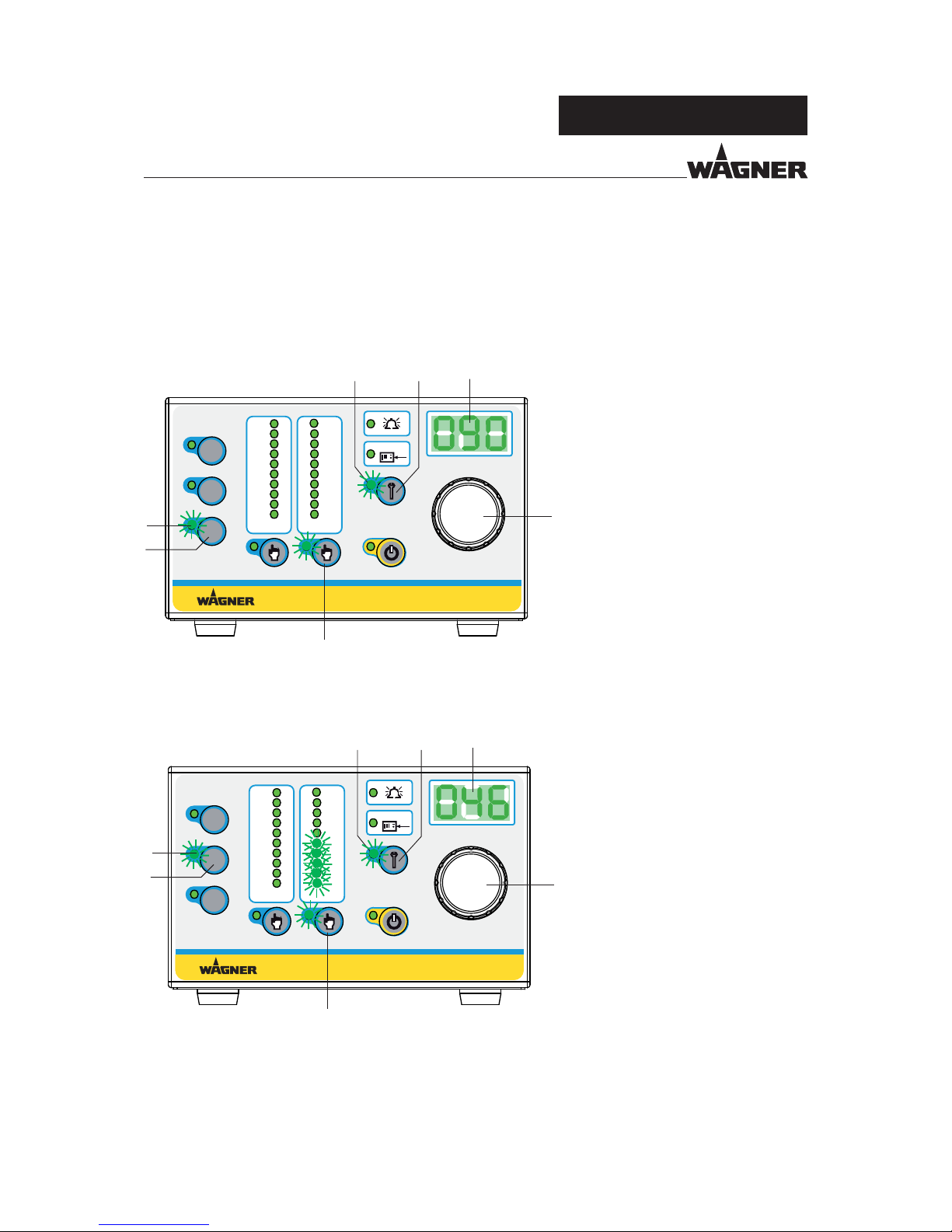
6.9.1 MAINTENANCE COUNTER SET UP AND READING
When using the device for the rst time, the function for the maintenance hours counter is
deactivated. This function can be activated with the "R3" push button (3). The maintenance
interval limit can be set within a range of 0 to 999 hours.
Setting and saving the service interval limit in hours
Procedure:
1. Press the push button (3) brie y.
Illuminated display (6) lights up.
2. Use the control dial (16) to set the
maintenance interval limit you
want (e.g. 90 hours).
3. Check setting on the display (15).
4. The value can be saved by
pressing and holding the push
button (19) until the indication in
the display (15) starts ashing.
Review counter reading since last service carried out on the gun
Procedure:
1. Press the push button (2) brie y.
Illuminated display (5) lights up.
2. Read display (15). In the example,
46 hours have passed since
realization of the last spray gun
service.
The vertical graph on the left
indicates that 50% of the set
interval time has passed.
3. By pressing and holding the
push button (19), you can reset
the display (15) to 0 (reset upon
expiry of set interval limit).
Page 35

35
VM 5000
1
2 3
4
1
2 3
4
1
2
3
4
5
6
7
8
B_03415
B_04167
Typ / Type: VM 5000
J. WAGNER AG
Industriestrasse 22
CH - 9450 Altstätten
Made in Switzerland
OPERATING MANUAL
EDITION 07/2014 ORDER NUMBER DOC 2344501
6.10 EXTERNAL INTERFACE
The control unit is equipped with an interface.
Before using it, you have to select the respective parameters in
the device con guration.
Control unit
Interface cable
External
release
Fault reset
Fault
output
HV input
μA input
HV output
μA output
+24V
DIN8
STN3PF06
LTV357
LTV357
GND
GND
GND
External release
GND >> Release
white
Fault reset
neg. edge >> Reset
brown
Fault output
24VDC >> Fault
green
HV input
7V >> 70kV
yellow
μA input
10V >> 100μA
gray
HV output
8V >> 80kV
pink
10V >> 100μA
blue
Ground
red
μA output
+24V
+24V
Page 36

36
VM 5000
OPERATING MANUAL
EDITION 07/2014 ORDER NUMBER DOC 2344501
Pin no. Designation Description
1 External release Potential-free contact between pin 1 and pin 8 (ground)
in - Closed Release issued
- Open Release not issued
2 Fault reset Potential-free contact (button) between pin 2 and pin 8 (ground)
in - If there is a fault, it can be acknowledged by pressing a button.
- Acknowledgement is only given via the negative edge.
3 Fault output If there is a fault, +24VDC is issued at pin 3 in reference to pin 8 (ground).
out
- Maximum current 0.5 A
4 DC kV in Set value speci cation for high-voltage
Analog DC current input between pin 4 in reference to pin 8 (ground)
in
- 0.1V corresponds to 1kV
- 8.0V is the maximum speci cation and corresponds to 80kV
5 DC μA in Set value speci cation for spray current limiting
Analog DC current input between pin 5 in reference to pin 8 (ground)
in
- 0.1V corresponds to 1μA
- 10.0V is the maximum speci cation and corresponds to 100μA
6 DC kV out Output of current working voltage
Analog DC current output between pin 6 in reference to pin 8 (ground)
out
- 0.1V corresponds to 1kV
- 8.0V is the maximum output and corresponds to 80kV
7 DC μA out Output of current working spray current
Analog DC current output between pin 7 in reference to pin 8 (ground)
out
- 0.1V corresponds to 1μA
- 10.0V is the maximum output and corresponds to 100μA
Page 37

37
VM 5000
OPERATING MANUAL
EDITION 07/2014 ORDER NUMBER DOC 2344501
7 OPERATION
Observe safety instructions in Chapter 4.
7.1 TRAINING THE OPERATING STAFF
7.2 SAFETY INSTRUCTIONS
Incorrect operation!
Risk of injury and equipment damage.
The operating sta must be quali ed to operate the entire system.
Before work commences, the operating sta must receive
appropriate training.
WARNING
Incorrect operation!
Risk of injury and equipment damage.
If contact with solvent-based paints or cleaning agents causes
skin irritation, appropriate precautionary measures must be
taken, e.g. wearing protective clothing.
The footwear worn by operating sta must comply with
EN ISO 20344. The measured insulation resistance must not
exceed 100 MΩ.
The protective clothing, including gloves, must comply with
EN ISO 1149-5. The measured insulation resistance must not
exceed 100 MΩ.
WARNING
Discharge of electrostatically charged components in atmospheres
containing solvents!
Explosion hazard from electrostatic spark-over.
Use gun only with tted nozzle, air cap and union nut.
WARNING
Page 38

38
VM 5000
EXT
100
80
60
40
20
μA
80
60
40
20
10
kV
R3
R1
R2
VM 5000
B_03682
_11
B_03294
B_03295
OPERATING MANUAL
EDITION 07/2014 ORDER NUMBER DOC 2344501
7.3 CONTROL UNIT START UP
1. Set toggle switch to position I.
2. For approx. 1 second all LEDs light up
-> Display test
3. The hardware and
High-voltage eld!
Danger to life from malfunction of heart pacemakers.
Make sure that persons with pace makers:
Do not work with the electrostatic spray gun.
Stay outside the area of the electrostatic spray gun/work piece.
DANGER
and software versions
are brie y shown,
one after the other, on
the display.
Page 39

39
VM 5000
EXT
100
80
60
40
20
μA
80
60
40
20
10
kV
R3
R1
R2
VM 5000
B_03682
_12
OPERATING MANUAL
EDITION 07/2014 ORDER NUMBER DOC 2344501
4. The control unit is ready for operation.
Note:
Each starting sequence is concluded
by allocating the saved set data in
recipe "R1".
7.4 SETTING AND SAVING RECIPES
Set values for the high-voltage (kV) and for the spray current limiting (μA) are stored in
a recipe. By default, the following values are saved at the factory in the 3 storage places
available for recipes:
Recipe No. Set value - high-voltage in kV Set value - spray current limiting in μA
R1 70 100
R2 60 100
R3 40 80
Recipes 1-3 can be selected and saved directly with the program buttons "R1", "R2" and
"R3". Once the recipe required has been called up, the individual coating parameters can
be called up and modi ed with the corresponding selection buttons (see Chapter 7.2.1
and 7.2.2). When a parameter is changed, the LED on the left of the program button goes
out and indicates to the user that a parameter value has been changed.
The process for saving parameters is described below.
To reuse the originally set values, press the program button brie y.
The modi ed values are not taken over.
However if the modi ed values should be saved, press and hold the corresponding
program button for approx. 2 seconds, until the LED beside the button starts to ash
quickly.
The modi ed values are then saved.
Page 40

40
VM 5000
EXT
100
80
60
40
20
μA
80
60
40
20
10
kV
R3
R1
R2
VM 5000
B_03682
EXT
100
80
60
40
20
μA
80
60
40
20
10
kV
R3
R1
R2
VM 5000
B_03682
_14
8
15
16
_13
22
21
OPERATING MANUAL
EDITION 07/2014 ORDER NUMBER DOC 2344501
7.4.1 SETTING THE HIGHVOLTAGE
The "High-voltage" bar graph display (8) is located above the "High-voltage" button (21).
If the control unit is in the ready position, this light strip shows the set value as a dot.
Procedure:
1. Press the "High-voltage" button (21) to
adjust the high-voltage.
The LED (22) indicates that high-voltage
is selected.
2. The high-voltage can now be adjusted
with the universal control dial (16)
between 5 to 70 kV with a resolution of
1 kV.
The corresponding value is indicated in
the LED display (15).
Page 41

41
VM 5000
EXT
100
80
60
40
20
μA
80
60
40
20
10
kV
R3
R1
R2
VM 5000
B_03682
EXT
100
80
60
40
20
μA
80
60
40
20
10
kV
R3
R1
R2
VM 5000
B_03682
_16
15
9
16
_15
15
19
20
OPERATING MANUAL
EDITION 07/2014 ORDER NUMBER DOC 2344501
7.4.2 SETTING THE CURRENT LIMITING
The "Current limiting" bar graph display (9) is located above the "Current limiting" push
button (19). If the control unit is in the ready position, this light strip shows the set value
as a dot.
The current limiting is an adjustable threshold. If this threshold is exceeded, for example by
the spray gun having approached the object being sprayed, the high-voltage is adjusted
downwards until the threshold is no longer exceeded.
The set values for high-voltage (40 kV) and for spray current limiting (83 mA) that are shown
in the examples, are saved in R2 by pressing and holding for a longer time the recipe push
button (for > 2 seconds).
Procedure:
1. Press the "Current limiting" button
(19) to adjust the limitation of the
spray current.
The LED (20) indicates that current
limiting is selected.
2. The current limiting can now be
adjusted with the universal control
dial (16) between 10 - 100 µA with a
resolution of 1 µA.
The corresponding value is indicated
in the LED display (15).
Page 42

42
VM 5000
EXT
100
80
60
40
20
μA
80
60
40
20
10
kV
R3
R1
R2
VM 5000
B_03682
EXT
100
80
60
40
20
μA
80
60
40
20
10
kV
R3
R1
R2
VM 5000
B_03682
_17
_18
OPERATING MANUAL
EDITION 07/2014 ORDER NUMBER DOC 2344501
7.4.3 DISPLAY DURING SPRAYING
Ready to spray using R2 recipe. See gure below.
Control unit in ready position.
The LEDs for the set values light up in a dot arrangement and the value for high-voltage is
displayed in digits. If you press the push button for current limiting, the adjusted set value
for the spray current limiting is displayed in digits.
Spraying using recipe R2.
By actuating the trigger on the spray gun, high-voltage is produced. The LEDs light up in
a bar and display the actual values. The current actual value for the activated push button
for high-voltage (kV) is displayed in digits. If the push button for the spray current limiting
is pressed, the respective LED lights up and the respective actual value appears in μA.
Page 43

43
VM 5000
EXT
100
80
60
40
20
μA
80
60
40
20
10
kV
R3
R1
R2
VM 5000
B_03682
EXT
100
80
60
40
20
μA
80
60
40
20
10
kV
R3
R1
R2
VM 5000
B_03682
_19
18
17
_20
OPERATING MANUAL
EDITION 07/2014 ORDER NUMBER DOC 2344501
7.5 STANDBY MODE
If you want to spray without high-voltage, select the standby mode.
Press push button (17) brie y and the "Standby" LED display (18) lights up. All the other
LEDs go out.
The previously saved "ready position" can be accessed from the standby mode (17) by
pressing the push button (17) again. See gure below.
Note:
This function can be activated and used from the gun.
Page 44

44
VM 5000
EXT
100
80
60
40
20
μA
80
60
40
20
10
kV
R3
R1
R2
VM 5000
B_03682
_21
13
14
OPERATING MANUAL
EDITION 07/2014 ORDER NUMBER DOC 2344501
7.6 DISPLAY "CONDUCT SERVICE"
Prerequisite:
The function "Maintenance interval limit" is activated.
"Conduct service on spray gun"
Once the time for the de ned maintenance interval has expired, the LED display (13) starts
to ash.
The ashing service display merely acts as a warning. You can continue working without
any limitations.
Page 45

45
VM 5000
EXT
100
80
60
40
20
μA
80
60
40
20
10
kV
R3
R1
R2
VM 5000
B_03271
1
2
3
4
5
16
21
6
7
192022 1718
13
8 9 12 1411
10
15
OPERATING MANUAL
EDITION 07/2014 ORDER NUMBER DOC 2344501
8 TROUBLESHOOTING AND RECTIFICATION
Functional fault Cause Remedy
No illuminated display lights up Mains supply not switched on Check and switch on mains supply
Fuses defective Replace fuses
Wagner Service
No high-voltage Spray gun cable not connected or
defective
Connect spray gun cable
Spray gun not connected or defective Wagner Service
Excessive conductivity of the lacquer See operating manual of spray gun
Fault LED (12) lights up
Fault message in display (15)
See the following table See the following table
Page 46

46
VM 5000
EXT
100
80
60
40
20
μA
80
60
40
20
10
kV
R3
R1
R2
VM 5000
B_03682
_22
12
14
15
OPERATING MANUAL
EDITION 07/2014 ORDER NUMBER DOC 2344501
Code
display
Fault Cause Remedy
E11 Ground monitoring
Grounding cable is interrupted Check/replace gun cable
Check/replace gun
Gun is not connected Connect gun
E12 No coil current/
cascade interrupt
Gun is not connected Connect gun
Gun cable is interrupted Check/replace gun cable
Cascade in gun is interrupted
--> defective
Check/replace gun
E13 Coil current too big
Cascade of the connected gun is
defective
Check/replace gun
E21-E29 Exception error Hardware defect has occurred If problem persists, contact Wagner
Service Team
E30 Cabinet door
monitoring
In Aquacoat operation: switching
on the high-voltage with an open
door
Close Aquacoat cabinet door
E40-E43 Gun communication
faulty
Gun cable defective Check/replace gun cable
Operating unit of spray gun defective Wagner Service
Control unit defective Wagner Service
E60 Password error
Password not set Password to be set by Service Center
The fault LED (12) indicates faults. In addition, the error number is shown in the 7-segment
display (15). If a fault occurs, high-voltage is immediately switched o . Work can only be
continued once the error has been remedied and acknowledged with the "Service" push
button (14).
Page 47

47
VM 5000
OPERATING MANUAL
EDITION 07/2014 ORDER NUMBER DOC 2344501
10 PRODUCT DISPOSAL
9 MAINTENANCE AND REPAIR
9.1 MAINTENANCE
9.2 REPAIR
The functionality and completeness of the control unit have to be checked regularly. All
sealed elements on the control unit must be present and undamaged. During operation,
all electric connections of the control unit have to be tightly sealed with the corresponding
plug connectors or closing elements.
The leakage tightness of the device has to be checked at least every 3 years. The "Restricted
breathing" requirements according to DIN EN 60079-15:2011 have to be ful lled. This
inspection may only be carried out by an authorized person or by trained Wagner Service
Personnel. When carrying out the leakage tightness test, the mains input terminal serves
as a test port.
Repairs to the control unit may only be carried out by trained Wagner Service personnel.
This also includes opening the control unit.
After repair has been completed, the control unit has to be checked for leaks. The "Restricted
breathing" requirements according to DIN EN 60079-15:2011 have to be ful lled. When
carrying out the leakage tightness test, the mains input terminal shall serve as test port.
Sparks form when live components are separated or connected!
Explosion hazard from electric sparks.
Do not disconnect plug connections under voltage.
Do not open fuse holders under voltage.
Do not remove the service plug cover under voltage.
WARNING
Do not dispose of used electrical equipment with household refuse!
In accordance with European Directive 2002/96/EC on the disposal
of used electrical equipment and its implementation in national
law, this product may not be disposed of with the household refuse,
but must be recycled in an environmentally correct manner.
Wagner or one of our dealers will take back your used Wagner
electric or electronic equipment and will dispose of it for you in
an environmentally-friendly way. Please contact one of our service
points, one of our representatives or us directly to arrange this.
NOTICE
Page 48

48
VM 5000
"?
"?
"?
B_03735
OPERATING MANUAL
EDITION 07/2014 ORDER NUMBER DOC 2344501
11 ACCESSORIES
Order No. Designation
241270 Mains cable Europe 3 m; 9.8 ft
2330628 Mains cable Europe 10 m; 32.8 ft
241271 Mains cable Switzerland 3 m; 9.8 ft
264626 Mains cable USA 2 m; 6.6 ft
264625 Mains cable Japan 3 m; 9.8 ft
2317600 Interface cable VM 5000, 10 m; 32.8 ft
130215 Grounding cable, 10 m, 32.8 ft
264332 Grounding cable, complete 0.75 m; 2.5 ft
2327509 Mounting control unit, complete
Note:
Hose sets and spray gun cables -> see operating manuals for spray guns
Page 49

49
VM 5000
OPERATING MANUAL
EDITION 07/2014 ORDER NUMBER DOC 2344501
12 SPARE PARTS
12.1 HOW CAN SPARE PARTS BE ORDERED?
Always supply the following information to ensure delivery of the right spare part:
Order number, designation, and quantity
The quantity need not be the same as the number given in the quantity column "
" on
the lists. This number merely indicates how many of the respective parts are used in each
component.
The following information is also required to ensure smooth processing of your order:
Billing address
Delivery address
Name of the person to be contacted in the event of any queries
Type of delivery (normal mail, express delivery, air freight, courier etc.)
Identi cation in spare parts lists
Explanation of column "
" (labeling) in the following spare parts lists:
Wearing parts
Note: No liability is assumed for wearing parts.
Not part of the standard equipment but available as a special accessory.
Incorrect maintenance/repair!
Risk of injury and equipment damage.
Have repairs and part replacements be carried out only by
specially trained sta or a WAGNER service center.
Before all work on the device and in the event of work interruptions:
- Switch o the energy/compressed air supply.
- Relieve the pressure from the spray gun and device.
- Secure the spray gun against actuation.
Observe the operating instructions for any work.
WARNING
Page 50

50
VM 5000
Typ / Type:
VM 5000
115VAC - 240VAC
50Hz / 60Hz
2344482
max. 40W
J. WAGNER AG
Industriestrasse 22
CH - 9450 Altstätten
Made in Switzerland
Serie Nr.:
Serial No.:
Spannung:
Voltage:
Artikel Nr.:
Article No.:
Eingangsleistung:
Input Power:
Spannung:
Voltage:
Strom:
Current:
max. 20Vpp
max. 1,0A
Eingangsstrom:
Input Current:
max. 0.5A
I
0
Main Switch
Prim.
1.0 AT
Nicht unter Spannung trennen!
Avertissement - Ne pas débrancher
sous tension!
Do not disconnect under voltage!
Schutzklasse:
Protection Class:
IP 54
B_04168
19
20
21
22
23
24
32
26
25
28
29
30
33
31
32
27
6
17
18
34
16
15
14
13
12
1
11
10
35
7
8
9
3
2
4
5
OPERATING MANUAL
EDITION 07/2014 ORDER NUMBER DOC 2344501
12.2 SPARE PARTS LIST VM 5000
Page 51

51
VM 5000
OPERATING MANUAL
EDITION 07/2014 ORDER NUMBER DOC 2344501
Pos Stk Order No. Designation
1 1 2344480 VM 5000 control unit
2 1 9903312 Recessed head raised llister head screw, H form
3 1 9952593 Protection cap for device socket
4 1 9950330 Safety clip for device sockets
5 2 9903306 Recessed head raised llister head screw, H form
6 1 9910102 Hexagon nut
7 1 9910522 High knurled nut
8 1 9920118 Washer
9 1 9922017 Serrated lock washer, externally toothed
10 2 9903311 Recessed head raised llister head screw, H form
11 1 241323 Cover, white
12 1 2350436 Print VM 5000 FM rear panel, complete (ET)
13 3 263400 Distance bush
14 3 9922011 Serrated lock washer, externally toothed
15 3 9910103 Hexagon nut
16 5 2312348 Hexagon lock nut
17 4 9922011 Serrated lock washer, externally toothed
18 4 9903312 Recessed head raised llister head screw, H form
19 8 2306405 Recessed countersunk at head screw, Z form
20 1 2307315 Seal
21 1 2307309 Cover
22 4 9990839 Bu er
23 1 9955176 Switching power supply
24 5 2309112 Spacer
25 1 2311875 Incremental encoder
26 1 2317539 Print complete VM 5000 display (with position 25)
27 1 2304462 Cover
28 1 2304461 Rotary knob
29 1 9953536 2-pin toggle switch
30 1 9952587 Connector plug
31 1 9955021 Fuse holder
32 2 9951117 Delay-action fuse 1.0 AT
33 1 9971519 Rubber seal
34 1 9955601 Fast-acting fuse 2.5A
35 1 2325264 Seal
Page 52

52
VM 5000
OPERATING MANUAL
EDITION 07/2014 ORDER NUMBER DOC 2344501
13 WARRANTY
13.1 IMPORTANT NOTES REGARDING PRODUCT LIABILITY
13.2 WARRANTY CLAIM
As a result of an EC regulation e ective from January 1, 1990, the manufacturer shall only
be liable for his product if all parts originate from him or are approved by him, and if the
devices are properly mounted, operated and maintained.
The manufacturer will not be held liable or will only be held partially liable if third-party
accessories or spare parts have been used.
With genuine WAGNER accessories and spare parts, you have the guarantee that all safety
regulations are complied with.
Full warranty is provided for this device:
We will at our discretion repair or replace free of charge all parts which within 24 months
in single-shift, 12 months in 2-shift or 6 months in 3-shift operation from date of receipt by
the purchaser are found to be wholly or substantially unusable due to causes prior to the
sale, in particular faulty design, defective materials or poor workmanship.
The type of warranty provided is such that the device or individual components of the
device are either replaced or repaired as we see t. The resulting costs, in particular
shipping charges, road tolls, labour and material costs will be borne by us except where
these costs are increased due to the subsequent shipment of the device to a location other
than the address of the purchaser.
We do not provide warranty for damage that has been caused or contributed to for the
following reasons:
Unsuitable or improper use, faulty assembly or commissioning by the purchaser or a
third party, normal wear, negligent handling, defective maintenance, unsuitable coating
products, substitute products and the in uence of chemical, electrochemical or electrical
agents, except when the damage is attributable to us.
Abrasive coating products such as red lead, emulsions, glazes, liquid abrasives, zinc dust
paints and so forth reduce the service life of valves, packings, spray guns, nozzles, cylinders,
pistons etc. Wear and tear due to such causes are not covered by this warranty.
Components that have not been manufactured by WAGNER are subject to the original
warranty of the manufacturer.
Replacement of a component does not extend the period of warranty of the device.
The device should be inspected immediately upon receipt. To avoid losing the warranty,
we or the supplier company are to be informed in writing about obvious faults within
14days upon receipt of the device.
We reserve the right to have the warranty compliance met by a contracting company.
The services provided by this warranty are dependent on evidence being provided in the
form of an invoice or delivery note. If the examination discovers that no warranty claim
exists, the costs of repairs are charged to the purchaser.
It is clearly stipulated that this warranty claim does not represent any constraint on statutory
regulations or regulations agreed to contractually in our general terms and conditions.
J. Wagner AG
Page 53

53
VM 5000
OPERATING MANUAL
EDITION 07/2014 ORDER NUMBER DOC 2344501
Page 54

54
VM 5000
OPERATING MANUAL
EDITION 07/2014 ORDER NUMBER DOC 2344501
Page 55

55
VM 5000
OPERATING MANUAL
EDITION 07/2014 ORDER NUMBER DOC 2344501
Page 56

C
E
R
T
I
F
I
E
D
Order No. 2344501
Edition 07/2014
Germany
Phone
Fax
E-mail
Switzerland
Phone
Fax
More contact adresses on the Internet at:
Enterprises/Sites/WAGNER worldwide
Subject to changes without notice
Document No. 11163742
Version -
 Loading...