

Page 1

Air sampling smoke detection system
Fire Detection
TITANUS
MICRO·SENS
Technical Manual
®
Page 2

Page 3

Air sampling smoke detection system
TITANUS
MICRO·SENS
Technical Manual
®
WAGNER Group GmbH
Schleswigstraße 1 - 5
D-30853 Langenhagen
Telephone +49 (0) 511 / 97383-0
Telefax +49 (0) 511 / 97383-140
E-Mail support@wagner.de
Internet www.wagner.de
Item Number 69-30-0525
Edition 06/13
Supersedes 01/09
Page 4

Page 5

TITANUS
MICRO·SENS
®
Contents
1 General 13
1.1 Introduction 13
1.2 Safety information 13
1.3 Guarantee 14
1.4 Copyright 14
1.5 Packaging 14
1.6 Disposal 15
2 Product Description 17
2.1 Characteristics of the TITANUS MICRO·SENS® aspirating smoke
detection system
17
2.2 Areas of Application 20
3 Technical Description 25
3.1 System Description 25
3.1.1 Function 26
3.2 TITANUS
MICRO·SENS
3.2.1 Overview 30
3.2.2 Air sampling smoke detection system 31
3.2.3 Detector box 33
3.2.4 Diagnostics tool 37
3.2.5 Network Modules 38
3.2.6 Remote displays 40
3.2.7 Reaction Indicator 41
®
and Accessories 30
3.3 Pipe system 42
3.3.1 Overview 42
3.3.2 Aspiration apertures for room monitoring 44
06/13
5
Page 6

TITANUS
MICRO·SENS
®
3.3.2.1 Aspiration reduction films 44
3.3.2.2 Aspiration reduction clips 45
3.3.3 Ceiling duct for concealed mounting 46
3.3.4 Air filters for dusty areas 48
3.3.5 Air return for pressure differences and air pollution 51
3.3.6 Noise suppressor 52
3.3.7 Steam trap for humid areas 53
4 Technical Data 55
4.1 TITANUS
MICRO·SENS
4.2 Detection box TITANUS
4.3 Accessories TITANUS
4.4 Pipe System – TITANUS
®
55
MICRO·SENS
MICRO·SENS
MICRO·SENS
®
57
®
58
®
60
5 Design 61
5.1 General 61
5.1.1 Regulations 62
5.1.2 Pipe systems 62
5.1.3 Air flow monitoring 66
5.1.4 Sensitivity 68
5.1.5 Design Limits 69
5.2 Project planning 70
5.2.1 Project planning guidelines 70
5.2.1.1 Determining the necessary accessories 70
5.2.2 Pipe accessories 71
5.2.3 Sensitivity and pipeline project planning 71
5.2.3.1 Pipeline project planning with pipe accessories 71
5.2.4 Aperture diameter 76
5.3 Special project planning 78
6
06/13
Page 7

TITANUS
MICRO·SENS
5.3.1 Project planning for individual aperture monitoring 78
5.3.1.1 I-Pipe system 78
5.3.1.2 U-Pipe system 79
5.3.1.3 M-Pipe system 81
5.3.1.4 Double-U-Pipe system 82
5.3.2 Simplified pipe design 84
5.3.2.1 I-Pipe system 84
5.3.2.2 U-Pipe system 85
5.3.2.3 M-Pipe system 86
5.3.2.4 Double U-pipe system 87
5.3.3 Project planning with branch pipe 88
®
5.3.4 Project design for forced air flow 91
5.3.5 Project design with air sampling hose 95
5.3.6 Project planning with air return 96
5.4 Power supply 98
6 Installation 101
6.1 General 101
6.2 Installation site 102
®
6.2.1 Fitting the TITANUS
6.2.2 Connecting the air sampling pipe 104
6.3 Incorporation and electrical connection of additional modules 106
6.4 Connection to FAS, with reset button 109
6.5 Incorporating the reset board 110
102
6.5.1 Connection to a FAS, with reset board 113
6.6 Incorporating the reset and isolating button board 114
6.6.1 Function switching plan, reset and isolating button board 115
6.7 Incorporating the relay board RU-1 / RU -2 116
6.7.1 Function switching plan, relay board RU-1 118
06/13
7
Page 8

TITANUS
MICRO·SENS
®
6.7.2 Function switching plan, relay board RU-2 119
6.8 TITANUS
MICRO·SENS
6.8.1 Installing the network module in the TITANUS
6.8.2 Connecting the network module to the TITANUS
®
in the network 120
MICRO·SENS
MICRO·SENS
®
120
®
123
6.9 Remote displays 124
6.9.1 Connecting the Remote displays to TITANUS
MICRO·SENS
®
124
6.9.2 Parallel display housing 125
6.9.3 Electrical connection 126
6.10 Reaction indicator 128
6.10.1 Addressing the reaction indicators 128
6.10.2 Connecting the reaction indicator to the TITANUS
MICRO·SENS
®
130
6.11 Inserting the detection unit in the device base unit 131
6.12 Settings 132
6.12.1 Detection Unit 132
6.12.1.1 Setting reaction sensitivity 133
6.12.1.2 Delay time for triggering the alarm 134
6.12.1.3 Threshold for air flow monitoring 134
6.12.1.4 Delay time for air flow fault 135
6.12.1.5 Action-Alarm Threshold 135
6.12.1.6 Fault display 136
6.12.1.7 Dynamic air flow 136
6.12.1.8 ROOM·IDENT 136
6.12.1.9 LOGIC·SENS 137
6.12.1.10 Fire Alarm threshold after ROOM·IDENT 137
6.12.1.11 Setting the fan voltage 137
6.12.1.12 Inputting the current air pressure 138
6.12.1.13 Inputting height above Normal Sea Level (NN) 138
6.13 Data Logging 139
8
06/13
Page 9

TITANUS
MICRO·SENS
7 Installation Pipe System 141
7.1 General assembly 141
7.1.1 Mounting pipe system 141
7.1.2 Mounting air sampling hose 143
7.2 Linear expansion of the pipe system 145
7.3 Patented air sampling points 147
7.4 Ceiling lead through 149
7.4.1 Ceilings feed-through for false ceiling 149
7.4.2 Other ceilings feed-through 150
®
7.5 Monitoring in forced air flow systems (ventilation or climatic
152
applications)
7.5.1 Detection at air inlets/outlets 152
7.5.2 Detection in bypass systems 153
7.6 Filter 154
7.6.1 Installation of air filter, type LF-AD-x 154
7.6.2 Mounting of the special filter type SF-400/650 155
7.7 Air return 157
7.8 Noise suppressor 158
7.9 3-Way ball valve 159
7.10 Steam trap 161
7.10.1 Steam trap type KA-DN-25 161
7.10.2 Steam trap type KA-1 162
7.11 Test adapter 163
06/13
9
Page 10

TITANUS
MICRO·SENS
®
8 Commissioning 165
8.1 Commissioning the detection unit 165
8.1.1 Plug and Play Commissioning 166
8.1.2 Commissioning with the diagnostics tool 166
8.2 Installing diagnostics software 168
8.3 Air flow sensor adjustment 170
8.3.1 Air Pressure-Independent Adjustment 171
8.3.2 Air Pressure-Dependent Adjustment 171
8.4 Testing the detection unit and alarm forwarding 173
8.5 Testing air flow monitoring 174
8.6 Testing fault forwarding 175
8.7 Testing the air flow sensor analysis function 175
8.7.1 Preparations for function testing 176
8.7.2 Carrying out function testing 178
8.8 Commissioning fire seat location 181
8.9 Commissioning the reaction indicators 185
9 Maintenance 187
9.1 Visual check 187
9.2 Testing detector and alarm forwarding 187
9.3 Testing pipe system 188
9.4 Exchanging the detection unit 189
10
9.5 Exchanging the air filter for the device base 190
9.6 Changing the filter on the type LF-AD-x air filter 191
9.7 Changing the filter on the SF 400/650 special filter 193
9.8 Pipe system blow through process 195
06/13
Page 11

TITANUS
MICRO·SENS
9.9 Checking the air flow sensor adjustment 197
9.10 Testing fire seat location and the reaction indicators 200
9.11 Testing Air Flow Monitoring 201
9.12 Testing Fault Forwarding 201
9.13 Maintenance Intervals 201
Appendix
®
Projection Tables
System Product List
Inspection Protocol
Glossary
Conformity certification pursuant to EU
06/13
11
Page 12

Page 13
TITANUS
MICRO·SENS
®
General
1
General
1.1
Introduction
This manual is for installers of air sampling smoke detection systems, in par-
ticular for engineers, technicians, and fitters etc. who have technical knowl-
edge in the field of smoke detection technology but who are possibly working
with this device for the first time.
For damage and faults resulting from the non-observance of this manual
WAGNER Group GmbH, called WAGNER in the following, does not assume
liability.
This manual refers to the air sampling smoke detection systems TITANUS
MICRO·SENS
1.2
smoke detection.
Safety information
®
. These systems may only be used for early and very early
The following symbols identify parts of the text in this manual which re-quire
special attention so that damage can be avoided and so that operations can
run smoothly.
WARNING
This symbol warns against actions,
which might cause damage if it is ignored.
NOTICE
This symbol warns against actions,
which could cause operational breakdowns if it is ignored.
TIP
Operational improvements can be achieved if this symbol is observed.
06/13
13
Page 14

General
TITANUS
MICRO·SENS
®
1.3
Guarantee
The manual is subject to technical modification without notice and makes no
claim to completeness.
In principle our “Terms and Conditions of Supply and Assembly” apply. No
claims under the guarantee or for liability can be made for damage to per-
sons or property if they are based on one or more of the following causes:
▪ insufficient observance of the instructions about the design, assembly of
the aspirating smoke detection system, assembly of the pipe system,
commissioning and maintenance
▪ use of the aspirating smoke detection system in contravention of the in-
tended use
▪ insufficient monitoring of working parts
▪ improperly executed repairs
▪ unauthorised constructional changes to the aspirating smoke detection
system
▪ force majeure
1.4
Copyright
The copyright in this Technical Manual remains with WAGNER.
The manual is designed exclusively for the assembler and his col-leagues.
Reproduction of the manual, including extracts, is not allowed. Copying or
distribution of the manual in any form is only allowed with permission in writ-
1.5
ing from WAGNER.
Packaging
The individual air sampling smoke detection systems are packed in accor-
dance with the anticipated transport conditions. Exclusively environ-mentally
friendly materials were used for the packaging.
The packaging is intended to protect the air sampling smoke detection sys-
tem from being damaged until it is installed. For that reason, it should only
be removed from its packaging shortly before installation.
The packaging material is to be disposed of in accordance with applicable
statutory provisions and local regulations.
14
06/13
Page 15

TITANUS
MICRO·SENS
®
▪ Dispose of the packaging materials in an environmentally friendly man-
ner.
▪ Observe local disposal regulations.
NOTICE
Packaging materials are valuable raw materials and in many cases can be
re-used or expediently processed and recycled. Improper disposal of pack-
aging materials can harm the environment.
General
1.6
Disposal
If no take-back or disposal agreements have been made, disassembled
components are to be taken for recycling:
▪ Take metal parts for scrapping.
▪ Take plastic parts to be recycled.
▪ Sort the remaining components by material quality and dispose of them.
▪ Give batteries to municipal collecting points,
or send them back to WAGNER Group GmbH.
06/13
15
Page 16

Page 17

y
TITANUS
MICRO·SENS
®
Product Description
2
Product Description
Locating the site of the fire
Sensitivit
2.1
Characteristics of the TITANUS
MICRO·SENS
aspirating smoke detection system
TITANUS
MICRO·SENS
smoke detection systems. The
equipment protection and for monitoring air conditioning cabinets or air con-
ditioning ducts. Through the innovative ROOM•IDENT process, the system
can also locate the site of the fire.
The unique ROOM·IDENT technology makes it possible to determine the lo-
cation of a fire when monitoring up to 5 separate areas. So that the emer-
gency services can act as quickly as possible, the seat of the fire can be
made known, for example, via reaction indicators which are allocated to the
various monitoring areas.
The
MICRO·SENS
®
is the latest generation of the renowned WAGNER
MICRO·SENS
®
reaction threshold can be set at between 0.1 %/m and 2
®
can be used for room and
®
Intelligent signal processing
Safe airflow monitoring
%/m light obscuration in steps of 0.1%/m. Using a smoke level indicator, an
indicator sensitivity of between 0.05 %/m and 0.2 %/m light obscuration can
be achieved. The HIGH-POWER-LIGHT-SOURCE light source technology
used in TITANUS
®
systems guarantees homogeneous reaction behavior
from different types of fire. The device can provide 2 alarm thresholds (pre
alarm and alarm). The pre-alarm threshold is adjustable from 10 - 80 % of
the fire alarm threshold.
THE TITANUS
MICRO·SENS
®
has LOGIC·
SENS
intelligent signal process-
ing for avoiding false alarms. Perfected algorithms based on numerous fire
trials and decades of experience ensure a high level of safety in differentiat-
ing between a false status and a fire event.
PIPE·GUARD, the comprehensive package for airflow monitoring, recog-
nises safe breakdowns such as pipe breakages or blocked detection aper-
tures Using dynamic airflow monitoring, the TITANUS
MICRO·SENS
®
reacts
even to small, quick changes in the airflow and thus makes an important
contribution to sabotage safety.
06/13
17
Page 18

y
y
Product Description
TITANUS
MICRO·SENS
Airflow monitoring is temperature-compensated and can be set to be air
pressure-dependent.
®
Redundancy ventilators
Network capacit
Plug and Pla
Installation and commissioning of the TITANUS
MICRO·SENS
®
are simple
with the Plug & Play function.
The device base is pre-assembled on site. By pre-setting the detection unit
for standard applications, the TITANUS
MICRO·SENS
®
is operational imme-
diately after it is inserted in the device base.
For maximum safety, the TITANUS
MICRO·SENS
®
can be fitted with redun-
dancy ventilators as an option. During operation of the device with the re-
dundancy ventilator, ROOM•IDENT is not possible.
Fitted with a network card, several TITANUS
MICRO·SENS
®
devices can be
linked together in an Ethernet network. From a central point the user can, for
example, via Visu
values etc. In addition, the TITANUS
LAN
T® monitor the whole plant for smoke levels, airflow
MICRO·SENS
®
can be integrated via
the so-called OPC server into existing hazard and building management sys-
tems.
Potential free contacts
Diagnostics
Designing detection points
The TITANUS
MICRO·SENS
®
has one potential free contact each for alarm
and fault So the smoke detection system can be switched to collective and
addressable (Via the address module of the particular FAS) recording lines
of any central fire alarm systems (FAS). A relay card (optional) can be con-
nected to the TITANUS
MICRO·SENS
®
in order to connect the potential-free
contact for the pre-alarm to a detector line of a CFDU.
With the DIAG 3 diagnostics device, there is a system available for commis-
sioning, inspection and servicing which makes it possible to configure the
device quickly and easily and contain faults. For diagnostics purposes
events are stored in the TITANUS
MICRO·SENS
®
for 72 hours.
The monitoring surfaces of the detection point type for the TITANUS
CRO·SENS
®
are to be set to match the point-specific smoke alarms. The de-
MI-
tection points can thus be designed similar to point-specific smoke alarms in
accordance with the particular national regulations.
18
06/13
Page 19

TITANUS
MICRO·SENS
Patented detection points
®
Product Description
Wagner’s patented detection reducing films, clips and banderols make as-
sembly simple and comfortable and avoid whistling operational noises. An
even inflow of air through all the apertures is achieved with a stepped aper-
ture diameter. These are fitted with rapidly checkable identification.
Extensive pipe accessories
Extensive range of accessories makes it possible to use the TITANUS® aspi-
rating smoke detection system even under the most difficult of conditions.
Products from various types of air filter from condensate traps to blow
through devices raise the serviceable life under extreme dusty, humid and
excessively cold environmental conditions.
06/13
19
Page 20

Product Description
TITANUS
MICRO·SENS
®
2.2
Areas of Application
The TITANUS
MICRO·SENS
®
air sampling smoke detection system is a fire
alarm system for the protection of rooms, equipment and air conditioning
Principle
ducts.
Air samples for a monitoring area are taken through the draw-off holes in a
pipe system and fed to the detection unit.
The principle is particularly suitable for areas in which point type alarms are
not used or can only be used to a limited extent.
This involves areas in particular …
▪ where is a high risk of fire,
▪ where high detection sensitivity is required,
▪ where false alarms must be avoided,
▪ which are difficult to access and in which it is difficult to mount and/or in-
spect point type alarms,
▪ where interrupting operations for inspection and servicing must be
avoided, • which are air conditioned,
▪ where the height is greater than is allowed for point type alarms,
▪ where for aesthetic reasons point type alarms are not wanted,
▪ where there are strong electromagnetic fields,
▪ which are subjected to high or low temperatures,
▪ which have a heavy dust load,
▪ where the fire alarm equipment must be protected against vandalism or
sabotage.
20
06/13
Page 21

TITANUS
MICRO·SENS
Room protection
®
Product Description
The TITANUS
MICRO·SENS
®
is suitable, for example, for monitoring rooms
such as, e.g.
▪ double floors, intermediate ceilings,
▪ tunnels, ducts, cavities not easily accessible,
▪ warehouses, deep freeze stores, lift shafts,
▪ museums, cultural establishments,
▪ hotel rooms, hospital rooms, offices, prison cells, railway compartments.
Figure 1: Principle of Room Monitoring with TITANUS MICRO•SENS® Smoke Detec-
tion System
06/13
21
Page 22

r
Product Description
Room monitoring with ai
Room monitoring takes place...
TITANUS
MICRO·SENS
®
conditioning
▪ in server rooms with air conditioning,
▪ in ventilation ducts,
▪ in double floors, intermediate ceilings,
▪ in IT rooms, E-distribution rooms, transformer cells,
▪ for air conditioning cabinets (see Fig. 1.2),
▪ at bypass of air conditioning ducts.
22
Figure 2: Monitoring options for a circulating air conditioning cabinet or an air condi-
tioning duct (principle representation).
The TITANUS® aspirating smoke detection system can also be used for ear-
liest detection of fires in rooms with special air conditioning.
Its high level of sensitivity means goods and equipment can be reliably moni-
tored. The TITANUS
®
is therefore especially suitable for areas of application,
▪ in which because of concentrated high values early intervention is nec-
essary.
▪ in which equipment must always be operational.
▪ in which highly sensitive detection is required (e.g. in areas where, be-
cause of built-in filter elements, there is a low level of smoke particles in
the air).
▪ in which there are high rates of air change.
06/13
Page 23

TITANUS
MICRO·SENS
Device protection
®
unventilated and force-ventilated equipment / cabinets such as, e.g.
▪ distribution cabinets, switching cabinets
▪ telephone switching equipment
▪ measuring, control and regulation equipment
Product Description
Figure 3: Equipment monitoring principle with air sampling smoke detection system
06/13
23
Page 24

Page 25

TITANUS
MICRO·SENS
®
Technical Description
3
Technical Description
3.1
System Description
The TITANUS
MICRO·SENS
®
aspirating smoke detection system comprises
a detection unit, device base and pipe system.
The most important components of the TITANUS
MICRO·SENS
®
are the
sensitive detection unit for picking up smoke aerosols and the aspiration unit
with integrated air flow sensor for transporting air samples and for monitoring
the pipe system for breaks and blockages.
The pipe system consists essentially of pipe and fittings, in either PVC or
ABS plastics.
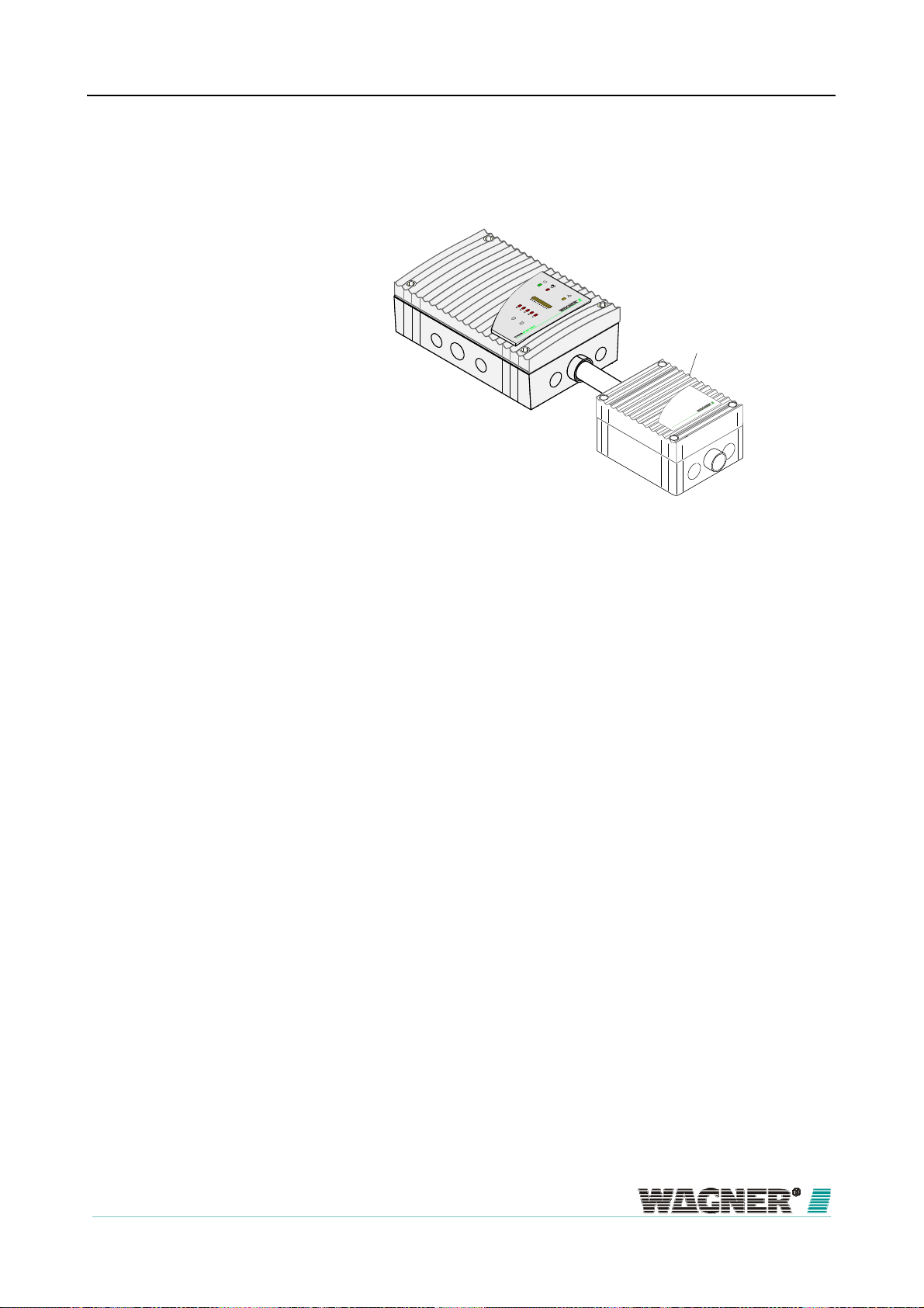
Figure 4: Air sampling smoke detection system TITANUS MICRO•SENS®
To guarantee safe operation even under the most difficult conditions (e.g.
recycling area), there are extensive accessories available such as, e.g., an
integrated air filter, various external air filters or the blow through device. In
very cold areas, a deep freeze version of the TITANUS
MICRO·SENS
®
can
be used. A redundancy ventilator can be used for applications where there
are particular safety requirements.
When fitted to monitor several monitoring areas and blind spots, there are
reaction indicators for rapid identification of the seat of the fire and an offset
parallel display as a status indicator for the detection unit.
06/13
25
Page 26

Technical Description
TITANUS
MICRO·SENS
®
Locating the site of the fire
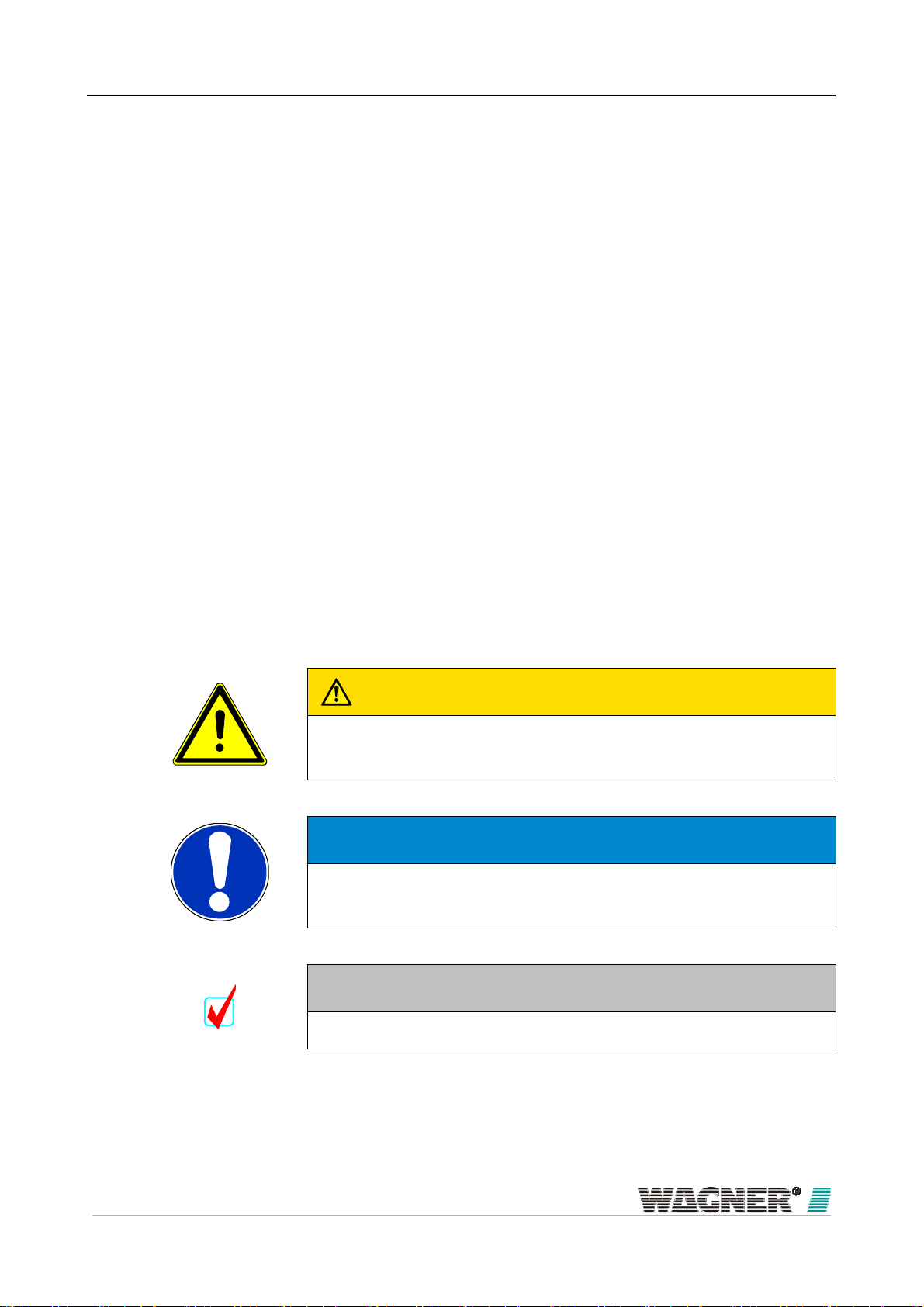
3.1.1
Phase 1
Function
Air samples are taken from the area to be monitored via a pipe system with
defined aspiration apertures, using the TITANUS
MICRO·SENS
unit and these are sent to the sensitive detection unit (see the following fig-
ure).
It is possible to locate the site of the fire using ROOM·IDENT with an I-pipe
design for a maximum 5 rooms or pieces of equipment. The operating prin-
ciple incorporates four phases:
During operating conditions air samples are taken from the pipes covering
the various rooms. The samples are taken via fan to the detector unit and
analysed for possible smoke particles.
®
aspiration
26
Phase 2
Figure 5: Phase 1 ROOM·IDENT standard operation
The system will activate an alarm once it has reached an alarm threshold
level due to the rise of typical smoke aerosols. If „Fire alarm after
ROOM·IDENT“ is enabled, then the localisation process will start after an ad-
justable Action - Alarm threshold. The system will activate an alarm once the
localisation is completed.
06/13
Page 27

TITANUS
MICRO·SENS
®
Figure 6: Phase 2 ROOM·IDENT earliest fire detection
Technical Description
Phase 3
In case alarm or at function „Fire alarm after ROOM·IDENT“ once the system
has reached the adjustable action the aspiration fan is switched off and a
second fan is switched on, blowing out the smoke particles in the opposite
direction.
Figure 7: Phase 3 ROOM·IDENT blow through
Phase 4
After the pipe system has been freed from smoke, the airflow is reversed
once again and the time it takes for the smoke to reach the detector unit is
measured. With this time value the exact location of the smoke source is
given and shows which room is affected.
06/13
27
Page 28
A
Technical Description
Figure 8: Phase 4 ROOM·IDENT localisation
The alarm is indicated on the TITANUS
TITANUS
MICRO·SENS
MICRO·SENS
®
itself, indicated
®
within the monitored area via an optical external alarm indicator. The System
with enabled option „Fire alarm after ROOM·IDENT“ will now activate an
alarm
Detection
Depending on the reaction sensitivity of the detection unit used (which can
be 0.1 %/m to 2 %/m light obscuration or 0.5 %/m to 2 %/m light obscura-
tion), the TITANUS
MICRO·SENS
®
triggers the main alarm once the corre-
sponding light turbidity is reached. The sensitivity can be set in steps of 0.1
%/m. The alarm is shown on the device via the alarm display and forwarded
to a connected fire alarm system (FAS).
By changing the delay time with the diagnosis tool, the forwarding of alarms
and faults can be set.
The intelligent LOGIC·
SENS
signal processing device serves to blank out
fire-like false alarms and ensures high false alarm safety.
irflow monitoring
An airflow sensor checks the connected pipe system for breaks and block-
ages.
Depending on the design of the pipe system and the setting on the air-flow
sensor, the blockage of just one aspiration aperture can be picked up. The
airflow monitoring is temperature-compensated and can be made air pres-
sure-dependent.
At the end of the adjustable delay time, the fault is shown on the smoke de-
tection system and a corresponding message is forwarded to the central fire
28
06/13
Page 29

A
TITANUS
MICRO·SENS
®
Technical Description
alarm point via a contact. The monitoring windows can be adjusted to the
environmental conditions.
The principle of the airflow sensor signalling process can be seen in the fol-
lowing figure.
Figure 9: Example signal pattern in the airflow sensor during faults
Device monitoring
irflow adjustment
The detection unit is monitored for dirt and signal fault. Any fault which oc-
curs is displayed at the TITANUS
MICRO·SENS
®
and can be forwarded to
the FAS via a contact.
Airflow adjustment on the TITANUS
MICRO·SENS
®
is fully automatic when
the detection unit is inserted in the device base, if previously the Jumper X4
had been changed. This plug & play reduces the time needed for commis-
sioning to a minimum. It is also possible, however, to adjust the airflow using
the DIAG 3 diagnosis tool. This means the initialisation phase can be carried
out in an air pressure-dependent or air pressure-independent manner.
Resetting through FAS
A fault message is reset via the connected FAS. If whilst the TITANUS
CRO·SENS
®
is operating an FAS alarm and fault [messages] have to be re-
MI-
set at the same time as the control line, then as an option a reset board can
be inserted in a separate housing. The reset board can only be placed in a
separate housing and if the idle current on the line is between 5 mA and 50
mA. The line must be switched to dead for resetting. The effect is that when
there is any short-term switching off of the line voltage, the alarm and fault
messages on the TITANUS
06/13
MICRO·SENS
®
are automatically reset.
29
Page 30

Technical Description
TITANUS
MICRO·SENS
®
3.2
3.2.1
TITANUS
Overview
Connections
FAS / Power supply
A
Pipe systems
B
Air return feed
C
to the next smoke
D
detection system
Indicator bus
E
Additional housing
(optional)
Network interface board
(optional)
MICRO·SENS
B
Relay platine RU-2
(optional)
Relay board RU-1
(optional)
Reset board
(optional)
Separation and reset
button (optional)
®
and Accessories
®
TITANUS
E
Fire alarm
cable
Parallel display unit
(optional)
Front film
(optional)
A
C
detector box
(optional)
D
30
Cable entries
M25
(optional)
Cable entries
M 20
(optional)
Test pipe
(optional)
Diagnostics tool
Figure 10: Overview TITANUS MICRO·SENS®
The components shown in the figure are optional.
06/13
Reaction indicator
(optional)
Page 31

TITANUS
MICRO·SENS
®
Technical Description
3.2.2
Air sampling smoke detection system
The TITANUS
MICRO·SENS
prises the following components, device base, detection unit and pipe sys-
tem:
Device base
▪ Connections for 25 mm aspiration pipe (in and return)
▪ Cable feeds
▪ Potential free contacts for connection to a FAS
Detection unit
▪ Sensitive detection using the latest technology according to the principle
of optical scattered light indicators with integrated airflow monitoring
▪ Aspiration unit with improved air feed
▪ Optical displays for smoke levels, fire alarm, action alarm, fault, opera-
tion and indication of the location of the seat of fire
▪ Infrared interface for diagnostics
®
air sampling smoke detection system com-
Figure 11: TITANUS MICRO·SENS® displays and connections
06/13
31
Page 32

®
Technical Description
TITANUS
MICRO·SENS
Figure 12: TITANUS MICRO·SENS® display variant with smoke levels and fire loca-
tion
®
TITANUS
MICRO·SENS
Numbers Function Explanation
1 Smoke level display 1 to 10
(10 yellow LEDs) (*)
Current smoke level
Operation (green LED) Operation display
Fire alarm (red LED) Smoke level (where fire
alarm threshold is set)
Action alarm (red LED) (*) Smoke level (Value as per
fire alarm threshold 10 – 80
% adjustable)
Fault (yellow LED) Pipe system fault or ventila-
tor breakdown or detector
module fault
Locating the seat of the fire A – E
Locating the seat of fire
(5 red LEDs) (*)
Infrared interface Commissioning and fault
diagnostics
2 Air sampling pipe connection
3 Cable feed, fire alarm cable for switching on
for ∅ 25 mm-pipe system
2 x M 25
FAS and/or power supply (in/out)
4 Air return pipe connection for air return
5 Cable feed fire alarm cable 8 x M 20
6 Cable entries (small) 2 x M 20 for cable with
∅ of 1 to 13 mm
7 Cable entries (large) 1 x M 25 for cable with
∅ 1 to 18 mm
(* optional)
32
06/13
Page 33

TITANUS
MICRO·SENS
®
Technical Description
3.2.3
Detector box
External detector boxes can be used in the pipe system in connection with
the TITANUS
The detector box is used …
Use
MICRO·SENS
®
smoke detection system.
▪ to create a two-detector or two-line dependency,
▪ to be able to locate the branch affected by smoke in multi-branch pipe
systems and/or
▪ to raise the reaction sensitivity in multi-branch pipe systems
Figure 13: TITANUS MICRO·SENS® function principle with detector box for two-
detector or two-line dependency
06/13
33
Page 34

Technical Description
TITANUS
MICRO·SENS
Figure 14: TITANUS MICRO·SENS® function principle with detector box for locating
and raising reaction sensitivity
®
The TITANUS
MICRO·SENS
®
detector box comprises the following compo-
nents:
Device base
▪ Connections for 25 mm aspiration pipe (in and out)
▪ Cable feeds
▪ Potential-free contacts for connection to a FAS
Detection unit
▪ Sensitive detection with the latest technology according to the principle
of optical scattered light detectors
▪ Optical displays for smoke level, fire alarm, action alarm, fault, operation
▪ Infrared interface for diagnostics
34
06/13
Page 35

TITANUS
MICRO·SENS
®
Figure 15: Detector box displays and connections
Technical Description
Figure 16: Display variant, detector box with smoke level and action alarm
06/13
35
Page 36

x
Technical Description
Detector bo
TITANUS
Numbers Function Explanation
1 Smoke level display 1 to 10
(10 yellow LEDs) (*)
Current smoke level
Operation (green LED) Operation display
Fire alarm (red LED) Smoke level (where fire
alarm threshold is set)
Action alarm (red LED) (*) Smoke level (Value as per
fire alarm threshold 10 – 80
% adjustable)
Fault (yellow LED) Pipe system fault or ventila-
tor breakdown or detector
module fault
Infrared interface Commissioning and fault
diagnostics
2 Air sampling pipe connection
3 Cable feed, fire alarm cable for switching on
for ∅ 25 mm-pipe system
2 x M 25
FAS and/or power supply (in/out)
5 Cable feed fire alarm cable 5 x M 20
6 Cable entries (small) 1 x M 20 for cable with
∅ of 8 to 12 mm
7 Cable entries (large) 2 x M 25 for cable with
∅ of 9 to 14 mm
(expandable to ∅ 14 to 18
mm)
(* optional)
MICRO·SENS
®
36
06/13
Page 37

TITANUS
MICRO·SENS
®
Technical Description
3.2.4
Diagnostics tool
Figure 17: Diagnostics tool for inputting and reading off device data
Using the DIAG 3 diagnosis tool, the device configuration for the TITANUS
can be changed during commissioning. For maintenance and servicing,
there is the option with the diagnosis software to display the stored and cur-
rent device status and error messages from the TITANUS
®
on a PC or lap-
top. For the data transfer to the diagnostics equipment the infrared interface
of the TITANUS
®
is used. There is a USB cable for transferring data from the
®
diagnostics equipment to the PC/laptop connection.
TIP
It is recommended that the commissioning statuses are read out, checked
and recorded.
Diagnosis messages can be deleted at any time using the DIAG 3 diagnosis
tool. If they are not deleted, the messages are stored in the TITANUS
®
for 72
hours. This allows for evaluation of short, sporadic faults (e.g. in changed
operating conditions).
06/13
37
Page 38

r
Technical Description
TITANUS
MICRO·SENS
®
3.2.5
Network Modules
Figure 18: Network card NU-2
The log data and status information of all TITANUS® air sampling smoke de-
tection systems can be stored with the TITANUS
Variants
tions in cold storage, special network modules for the TITANUS
The TITANUS® network module is available in various configurations for the
®
network card. For applica-
®
available.
respective areas:
Type
NU-2 X X X
NU-2-D X X X X
NU-2-DO X
NU-2-D-F X X X X X
TCP/IP
NU-2-DO-F X X
With the help of this standard transfer protocol, the TITANUS® air sampling
TCP/IP SNMP Webserver Datenlogger Deep freezer
Application
38
SNMP
Data logge
smoke detection system can be connected to the risk management system
(e.g Visu
LAN
). All status information, as well as event and log data are
available as to the risk management.
The status information and log data stored in network cards on all TITANUS®
air sampling smoke detection systems can be accessed via the SNMP pro-
tocol. By installing SNMP management software, customers can constantly
visualise and monitor the TITANUS
®
air sampling smoke detection systems.
When an incident occurs (e.g. a threshold is exceeded), an alert or a fault
message is sent to a managing entity or directly to another network partici-
pant via SNMP-Traps.
The integrated data logger is used to record event data (alerts and faults)
and log data (smoke level, air flow, air flow temperature, detection status,
temperature sensors) from TITANUS
®
air sampling smoke detection system.
The event and log data are saved on a memory card at pre-defined logging
06/13
Page 39

r
TITANUS
MICRO·SENS
Web serve
®
Technical Description
intervals of 1-60 seconds. The logged data saved can be analysed in the TI-
TANUS
®
DataView and TITANUS® EventView software programs supplied.
For network modules with embedded web server, it is possible to display
current data and status information device specific on a predefined display
panel and is easily accessible via a standard Web browser. The benefit for
users is that it is both convenient and easy to use. After successful setup,
the information is available immediately without any special network installa-
Multi-application
tion required. A special setup of the Web server is not necessary.
The TITANUS® network card has four TCP/IP channels that support multi-
application operation. Four TCP/IP applications can communicate simulta-
neously with a network card and additional data logger and SNMP data can
be accessed.
NOTICE
When multi-application mode is used, this can cause delayed Website
loading in the Web browser.
Write protection
Write protection can be activated on the network board via the jumper to pro-
tect parameter settings. Once successfully set up, network settings can be
protected against overwrite.
06/13
39
Page 40

Technical Description
TITANUS
MICRO·SENS
®
3.2.6
Remote displays
Figure 19: Remote display for wall mounting
The TITANUS
MICRO·SENS
more remote displays. The displays on the remote display are identical to
those on the detection unit. The connection is made in the TITANUS
CRO·SENS
®
device base.
A remote display can be connected up to a distance of 1000 m. If a second
®
offers the possibility of connecting one or
MI-
remote display [sic] is connected behind the first one, this can in turn again
be 1000 m from the first one. This is possible as each remote display is also
a repeater.
The power supply for small distances is direct through TITANUS
CRO·SENS
®
, and for longer distances via an external supply (see Chapter
MI-
design "Power Supply Calculation").
40
06/13
Page 41

TITANUS
MICRO·SENS
®
Technical Description
3.2.7
Reaction indicator
Figure 20: Reaction indicator for locating the site of a fire
When the TITANUS
MICRO·SENS
dressable reaction indicators can be used via the indicator bus.
®
is used with fire location, up to 5 ad-
The r eaction indicator can be connected up to a distance of 1000 m.
06/13
41
Page 42
Technical Description
TITANUS
MICRO·SENS
®
3.3
3.3.1
Pipe system
Overview
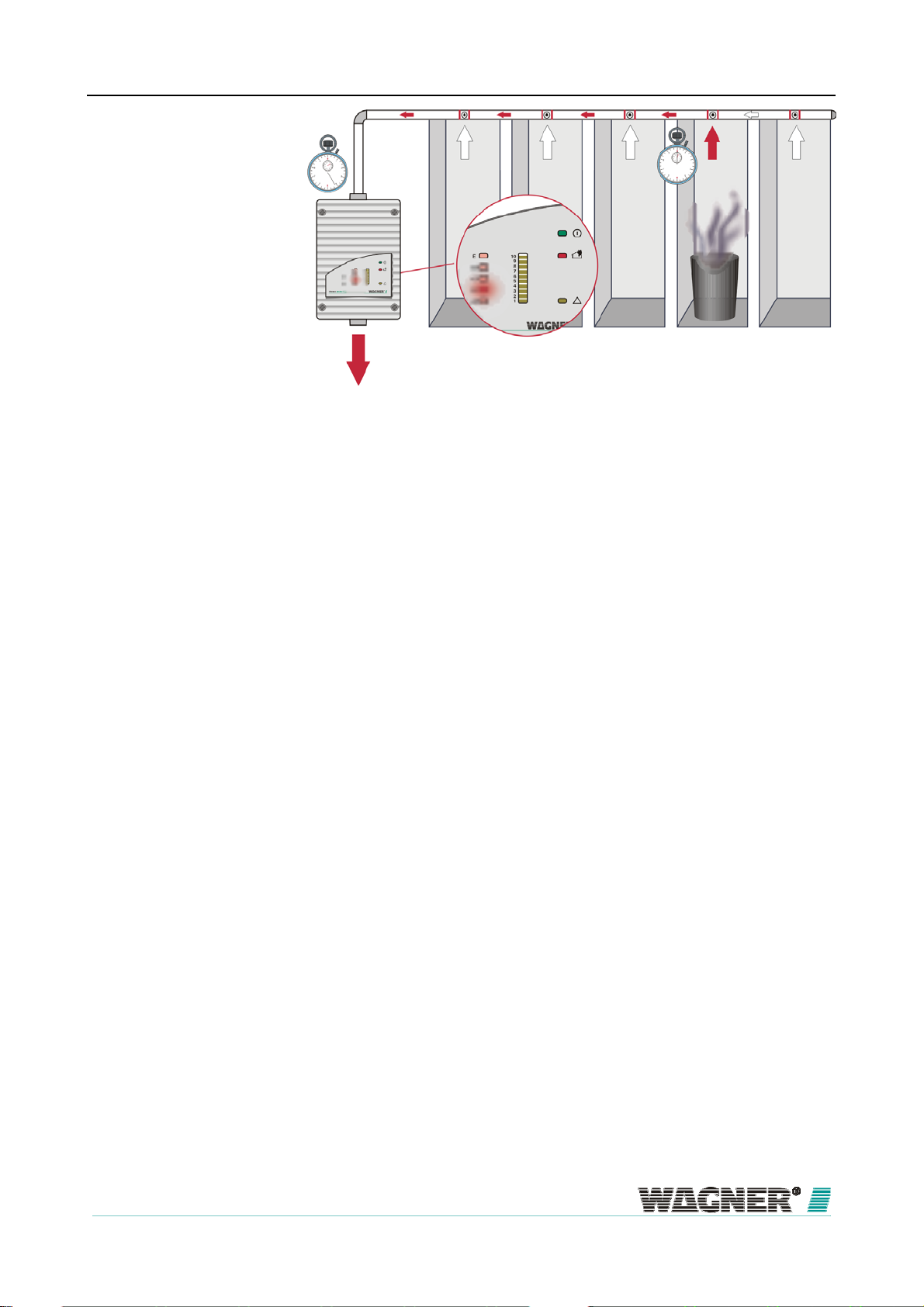
Connections
pipe system
A
90° arc
A
steam trap
A
sleeve
A
air
sampling
hose-
ceiling feed
through
45°- elbow
90° elbow
air sampling
hose
air filter
TITANUS
special filter
T- p i e c e
air sampling pipe
test adapter
®
End cap
non-return valve
reducer coupling
aspiration reducing
film sheet
marking tape for AF
noise suppressor
DF-Clip
pipe cap
air flow reducer
pipe with PG16
internal thread
A
Figure 21: Components of the pipe system for smoke detection systems
The accessories shown in the figure are to be chosen for the particular indi-
Free blow device
vidual case and can be used in combination.
In areas in which there is expected to be an increased occurrence of dust
particles or ice formation, blowing through of the aspiration pipe system and
aspiration apertures may be necessary. Figures each show the components
of a manual and an automatic blowing-out system. Depending on the fre-
42
06/13
Page 43

TITANUS
MICRO·SENS
®
Technical Description
quency of blockages, the blow-throng process can be undertaken manually
or automatically.
Figure 22: Components of the manual blowing-out system
Figure 23: Components of the automatic blowing-out system
06/13
43
Page 44
Technical Description
TITANUS
MICRO·SENS
®
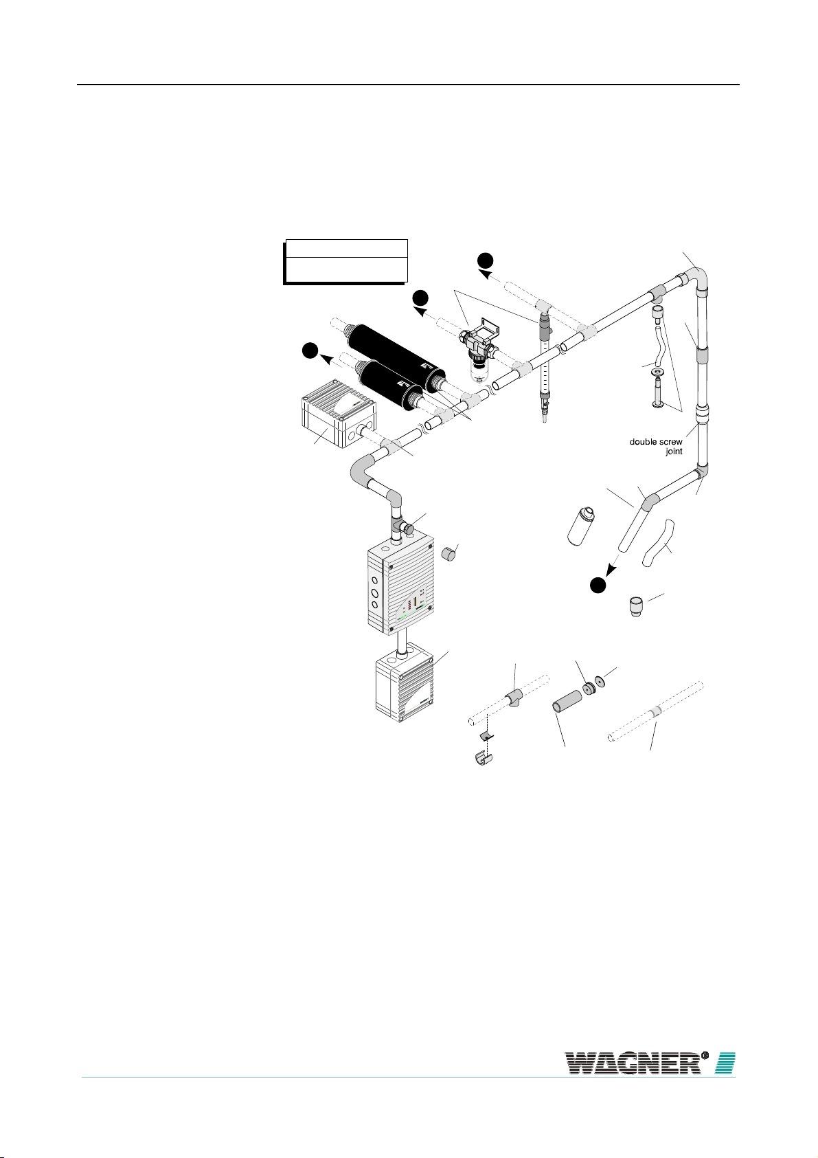
3.3.2
3.3.2.1
Aspiration apertures for room monitoring
Aspiration reduction films
Figure 24: Aspiration aperture with aspiration reduction film and banderol
An air sampling point is a 10 mm-hole in the air sampling pipe covered with a
patented aspiration-reducing film sheet with the appropriate opening diame-
ter. The size of the opening depends on the pipe design (see chapter De-
sign, “Pipe Design”).
To prevent the film sheet from coming loose, it is fixed with transparent
marking tape with red edges and a 10 mm-hole. The marking tape is fixed to
the film sheet in such a way that the air sampling point is not covered and
remains visible even at a distance.
The standard type AF-x aspiration reduction films and the type AF- bande-
rol’s are not suitable for use in very low temperature areas.
Aspiration reduction clips are to be used in these areas instead.
44
06/13
Page 45

TITANUS
MICRO·SENS
®
Technical Description
3.3.2.2
Aspiration reduction clips
Figure 25: Air flow reducer for dirty areas and deep freeze storage
The air sampling points, when used in areas where blockages can occur, are
equipped with a patented plastic clip, type AK-C, and a patented flexible air
flow reducer, type AK-x.
When used in deep freeze areas, the flexible air flow reducer near the air
sampling points expands and the ice is blasted off during blow-through. The
special plastic clip ensures that the air flow reducer remains in place.
For designs in areas requiring a blow-through system (e.g. dusty), air flow
reducers with plastic clips are used rather than aspiration-reducing film
sheets with marking tapes, because the openings can be blown clear more
easily. The plastic clips are more resistant at high pressures and can be
cleaned more effectively due to the rubber core.
06/13
45
Page 46

A
Technical Description
TITANUS
MICRO·SENS
®
3.3.3
Ceiling duct for concealed mounting
Figure 26: Ceiling feed-through for ceiling voids
esthetics
If a hidden installation is required for monitoring of the pipe system, it can be
installed in the ceiling void. The ceiling feed through are put in the false ceil-
ing. According to the pipe design guidelines the ceiling feed-through are
equipped with aspiration-reducing film sheets with defined air sampling
points (see chapter Design "Pipe Design") and are connected to the pipe
system with air sampling hoses.
If the maximum length of these hoses is 1 m, refer to the pipe design de-
scribed in chapter "Design". If - due to construction - hose lengths of more
than 1 m are required, the air sampling pipe system must be calculated
separately (calculation is made by WAGNER).
The ceiling feed through is applicable for false ceiling panels with a thickness
of up to approximately 35 mm. The aspiration-reducing film sheets are avail-
able in two colours (pure white, RAL 9010 and papyrus white, RAL 9018)
and come ins special colours if required.
46
06/13
Page 47

TITANUS
MICRO·SENS
®
Technical Description
Pipe cap
2
Air flow reducer
(Aperture plate)
1
Hose connection
Air sampling hose
Figure 27: Capillary hose Installation and upstream aperture
For hidden installation in example lamps or stucco, the air sampling hose
with upstream aspiration reduction in the tees (pipe caps) are used.
Ceiling feed through (part)
3
06/13
47
Page 48

r
r
Technical Description
TITANUS
MICRO·SENS
®
3.3.4
Air filters for dusty areas
Figure 28: TITANUS MICRO•SENS® with air filter
In areas with interference to the environment such as, e.g. dust, an air filter
Type LF-AD-x air filte
is to be used to protect the smoke detection system.
The standard air filter used is the type LF-AD-x, consisting of a plastic hous-
ing with two pipe connections, used. The air filter is automatically monitored
for dirt (blockage) by the TITANUS
MICRO·SENS
®
air flow monitoring ar-
rangement. If the air filters are dirty, then the filter inserts must be changed
Special type SF-x filte
by opening the filter housing.
In extremely dusty areas (e.g. recycling plants) in which the use of an LF-AD
is not sufficient, a special filter must be used. The special filter safely holds
back the dust particles in a heavily polluted atmosphere using the filter me-
dium. The filter is guaranteed to have an even quality of dust collection right
through to the end of its useful life. Two types of special filter are available
(type SF-400 and type SF-650), the SF-650 having a longer useful life be-
cause of its larger surface area.
48
06/13
Page 49

TITANUS
MICRO·SENS
®
Figure 29: Special Filter and LF-AD
Technical Description
The filter life of special filter can be increased by the use of an upstream filter
LF-AD.
LF-ADLF-ADLF-ADLF-AD
Figure 30: LF-AD filters in multiple sampling pipes
06/13
TITANUS
®
49
Page 50

Technical Description
TITANUS
MICRO·SENS
In order to extend the maintenance intervals, one air filter can be installed in
every output pipe instead of one air filter inside the main sampling pipe. The
same design specifications shall apply as stated in the projection tables in
the appendix.
LF-ADLF-ADLF-ADLF-AD
®
TITANUS
®
Figure 31: LF-AD filter in the main sampling pipe
Furthermore, in order to extend the maintenance intervals, several air filters
can be installed in parallel in the main sampling pipe. This requires the main
sampling pipe to be split into one or several pipes and to be equipped with
the same air filter or the combination of air filters. The individual pipes can
then alternatively be either combined again to one main sampling pipe or be
separately continued into the monitoring area(s). The same design specifica-
tions for the individual air filters shall apply as stated in the projection tables
in the appendix.
50
06/13
Page 51

TITANUS
MICRO·SENS
®
Technical Description
3.3.5
Air return for pressure differences and air pollution
Figure 32: Principle of air return with TITANUS MICRO· SENS®
If TITANUS
MICRO·SENS
P1 and P2 – each with different air pressures, the air must be returned to the
pressure area of the pipe system. The air return can be used for pressure
®
and the pipe system are installed in two areas -
compensation or in order to keep the air clean (e.g. from odours) in adjacent
rooms.
Figure 33: TITANUS MICRO·SENS ® with air return
The air return pipe system is directly connected through the protection grid to
the air outlet inside TITANUS
MICRO·SENS
®
. As the air return pipe fits pre-
cisely into the air outlet a firm hold is ensured.
06/13
51
Page 52
Technical Description
TITANUS
MICRO·SENS
®
3.3.6
Noise suppressor
TITANUS
MICRO·SENS
®
C
SD-1
Figure 34: TITANUS MICRO·SENS with noise suppressor
By using the SD-1 noise suppressor, the noise level can be reduced by up to
10 db(A) for use in areas in which low noise emissions are required from the
TITANUS
MICRO·SENS
®
(such as in offices or hospitals).
The noise suppressor is mounted directly to the air outlet on the TITANUS
MICRO·SENS
®
.
52
06/13
Page 53

TITANUS
MICRO·SENS
®
Technical Description
3.3.7
Steam trap for humid areas
Figure 35: Steam trap to eliminate water vapour from the pipe system and to collect
the condensate from the pipe system
Figure 36: KA-1 to eliminate water vapour from the pipe system and to collect the
condensate from the pipe system
06/13
53
Page 54

A
Technical Description
The TITANUS
MICRO·SENS
TITANUS
®
is used in environments with high humidity
MICRO·SENS
condensate can occur in the air sampling system. In order to collect this
condensate the steam trap is installed at the deepest point of the pipe sys-
tem before the air filter and the air sampling smoke detection system. The
45°-elbows permit an optimum distance to the wall.
The steam trap can be operated in a temperature range between 0°C and
+50°C. The sinter filter in the steam trap has a pore width of 50 µm and ab-
sorbs also coarse dirt particles.
®
pplication
The steam trap is used in the following areas:
▪ Areas with severely oscillating temperatures and high air humidity
▪ External areas
▪ Sauna areas
54
06/13
Page 55

t
t
TITANUS
MICRO·SENS
®
Technical Data
4
NOTICE
All power consumption figures relate to an ambient temperature of 20°C.
Technical Data
4.1
TITANUS
MICRO·SENS
®
Voltage
Curren
Power supply (Ue)
Nominal power supply
U
1= 9 V
L
(at 24 V)
Starting current (1) 150 mA
Power consumption at idle status (1) 105 mA 125 mA 145 mA 170 mA
Power consumption at alarm
status(1)
110 mA 130 mA
Device variant without smoke level
Power consumption at alarm
Outputs
Dimension
Weigh
Noise Level
Device variant with smoke level
(1) (without extra modules) UL = Fan voltage
Contact loading capacity of the
alarm and fault relay
Dimension (H x W x D mm) 70 x 140 x 222 mm
Weight 0.8 kg
Lpa according to EN ISO 3744, 1995 at 40 dB(A)
status(1)
140 mA 160 mA
depending on the configuration and fan voltage
TITANUS MICRO·SENS®
16 - 30 V DC
UL1= 10.5 V
(at 24 V)
1A / 30 VDC
24 V DC
UL1= 12 V
(at 24 V)
150 mA
180 mA
UL1= 13.5 V
(at 24 V)
175 mA
205 mA
06/13
55
Page 56

®
y
y
Technical Data
Protection classification
Temperature range
Displays on device
Infrared interface
Reaction sensitivit
Housing
Humidit
Fan
Connections
Protection classification (EN 60 529)
without air return
with pipe piece 100 mm/pipe bend
with air return
material plastic (ABS)
TITANUS MICRO·SENS
deep freeze variety
not condensed max. 95 % rf (without dew)
Type of construction axial
service life of fan (12 V) 60.000 h at 24° C
Operation
Fire alarm
Action alarm
Smoke level display
Alarm location display
Infrared interface IR
Device connection Clips for
Cable feeds
device base
Device base floor
conical
pipe plug-in connections
Detection unit
DM-TM-10 0.1 to 2.0 % light obscuration/m
DM-TM-50 0.5 to 2.0 % light obscuration/m
TITANUS
MICRO·SENS
IP 20
IP 42
IP 54
colour papyrus white, RAL 9018
– 20° to +60°C
– 40° to +60°C
green operating display
red alarm display
red alarm display (optional)
Fault
yellow collective fault
yellow smoke level display 1 to 10
(10 segments) (optional)
5 red displays (optional)
Transmitter/ Receiver
0.5 – 2.5 mm²-wires
Cable pair twisted,
8 x M 20
2 x M 25
4 x M 25
1 x for aspiration pipe
∅ 25 mm and
1x air return
∅ 25 mm
®
56
06/13
Page 57

r
t
y
TITANUS
MICRO·SENS
®
Technical Data
4.2
with Smoke level and
Voltage
Processo
Detection box TITANUS
MICRO·SENS
Power supply (Ue)
Nominal power supply
Power consumption at idle status 30 mA
Power consumption at alarm status
Detection box
15 - 30 V DC
24 V DC
38 mA
®
Device variant without smoke level
Power consumption at alarm status
Temperature range
Displays on device
Dimensions
Weigh
Protection class
Housing
Humidit
Device variant with smoke level
Dimension (H x W x D mm) 70 x 140 x 222 mm
Protection class (EN 60 529) IP 54
Deep freeze version
Weight 0.8 kg
material plastic (ABS)
colour papyrus white, RAL 9018
Detection box
not condensed max. 95 % rf (without dew)
Operation
green operating display
Fire alarm
Action alarm
red alarm display (optional)
Fault
Smoke level display
Infrared interface
Infrared interface IR
yellow smoke level display 1 to 10
(10 segments) (optional)
68 mA
– 20° to +60°C
– 40° to +60°C
red alarm display
yellow collective fault
Transmitter / Receiver
06/13
57
Page 58

y
y
t
Technical Data
Reaction sensitivit
Connections
TITANUS
MICRO·SENS
®
Device connection Clips for
Cable pair twisted
Cable feeds
Detection box base
Detection box base floor
conical
Pipe plug-in connections
0,5 - 2,5 mm²- wires
8 x M 20
2 x M 25
4 x M 25
2 x for aspiration pipe
∅ 25 mm
Detection unit
DM-TM-10 0.1 to 2.0 % light obscuration/m
DM-TM-50 0.5 to 2.0 % light obscuration/m
4.3
Accessories TITANUS
MICRO·SENS
®
Parallel display for
Parallel displa
Voltage
Nominal voltage
Power consumption (at 24 V)
Idle
maximum
Temperature range
Dimension
Weigh
Protection class
Housing
electr. connection lengths max. 1000 m
Dimension (H x W x D mm) 70 x 140 x 200 mm
Weight 0.6 kg
Protection class (EN 60 529) IP 54
Material Plastic (ABS)
Colour papyrus white, RAL 9018
Parallel display – 20° to +60°C
TITANUS MICRO·SENS
24 V
15 mA
50 mA
®
58
06/13
Page 59

r
TITANUS
MICRO·SENS
Displays on device
Reaction indicato
Relay board RU-1/RU-2
Network module
®
Connections
Cable feeds
Reset board
Operation
Fire alarm
Action alarm
Smoke level display
Alarm location display
Parallel display base
Parallel display base floor
Nominal voltage
Power consumption (at 24 V)
Blink light
Steady burning
electr. connection lengths 1000 m
Protection class (EN 60 529) IP 30
Dimensions 98 x 94 mm
Temperature range -40 °C to +60 °C
Contact loading capacity of the
relay contacts
Power consumption (at 24 V) RU-1
Idle status
Alarm status
Power consumption (at 24 V) RU-2
Idle status
Alarm status
Power consumption max. 20 mA
Power consumption max. 50 mA
green operating display
red alarm display
red alarm display (optional)
Fault
yellow collective fault
yellow smoke level display 1 to 10
(10 segments) (optional)
5 red displays (optional)
Clip strip Clips for
max. 2.,5 mm²-wires
Cable pair twisted,
8 x M 20
2 x M 25
4 x M 25
Voltage
15 to 30 V DC
24 V DC
Stand by
2 mA
5 mA
8 mA
1 A at 30 V DC
6 mA
max. 36 mA
13 mA
max. 36 mA
Technical Data
06/13
59
Page 60

Technical Data
TITANUS
MICRO·SENS
®
4.4
Pipe length
Pipe System – TITANUS
max. pipe length ∅ 25 mm
plus max. pipe length ∅ 12 mm
MICRO·SENS
Pipe System for TITANUS MICRO·SENS®
50 m
8 x 3 m
®
max. no. aspiration apertures 8
max. length aspiration hose
per ceiling duct
Temperature range
PVC-pipe
ABS-pipe
max. monitoring surface area 400 m2
1 m
-0°C..+60° C
-40°C..+80° C
60
06/13
Page 61

TITANUS
MICRO·SENS
®
5
Design
Design
5.1
General
The following describes the project planning of the air sampling smoke de-
tection system to EN 54-20 or ISO 7240-20. The basic conditions are de-
scribed in Chapter 5.1. The basic conditions are described in Chapter 5.1.
The project planning is to be conducted in accordance with Chapter 5.2.
The limiting project planning instructions in accordance with Chapter 5.2 ap-
ply to special applications in addition to Chapter 5.3 These should be taken
into consideration at the beginning of project planning for special projects.
Project planning options according to EN 54-20 or ISO 7240-20:
There are various technical solutions to be selected from, depending on the
project planning criteria. The chapters for the solutions are listed in the fol-
lowing tables.
Project planning
criterion
General area
monitoring
Recognition of a failure
at an individual aperture
Device protection /
cabinet monitoring
Ventilation conduits Project planning for forced
Technical solution Basic Principles Limitations
Standard project planning Chapter 5.2 _
Project planning for individual aperture monitoring
Simplified pipe project
planning
air flow
Chapter 5.2 Chapter 5.3.1
Chapter 5.2 Chapter 5.3.2
Chapter 5.2 Chapter 5.3.5
06/13
61
Page 62

Design
TITANUS
MICRO·SENS
®
5.1.1
Regulations
The current respective national regulations in each particular country must
also be complied with and project planning must be adjusted to such regula-
tions.
EN 54-20 or ISO 7240-20
The air sampling smoke detection systems shall be planned in accordance
with the project planning guidelines described in Chapter 5.2.1 in order to be
compliant with EN 54-20 or ISO 7240-20.
The following guidelines must also be complied with for systems in accor-
dance with the requirements of VdS Schadenverhütung:
▪ "Guideline for automatic fire alarm systems, planning and installation",
VdS Schadenverhütung GmbH, Cologne, Germany (VdS 2095)
▪ "Local application protection for electric and electronic equipment rules
for planning and installation" guideline, VdS Schadenverhütung GmbH,
Cologne, Germany (VdS 2304)
▪ The technical bulletin “Project Planning for air sampling fire alarms” VdS
Schadenverhütung GmbH, Cologne, Germany (VdS 3435)
The following national regulations must also be complied with in Germany,
for instance:
▪ DIN VDE 0833 part 1 and 2 "Alarm systems for fire, intrusion und hold-
up"
▪ Additional regulations for installing fire alarm systems which are laid
down by fire authorities and building supervisory boards or building regu-
5.1.2
lation authorities and are only valid locally.
Pipe systems
When planning the pipe system, it must be ensured that reliable fire detec-
tion is guaranteed for any fire present in an installation or in a monitored
area.
The number of the intake apertures and the pipe system design depends on
the size, ventilation and shape of the monitored area. The aspiration aper-
tures should be planned like point-type detectors. The pipe system is to be
fitted in accordance with the project planning guidelines in this section while
62
taking the following points into consideration:
06/13
Page 63
TITANUS
MICRO·SENS
®
Symmetry of the pipe system
Design
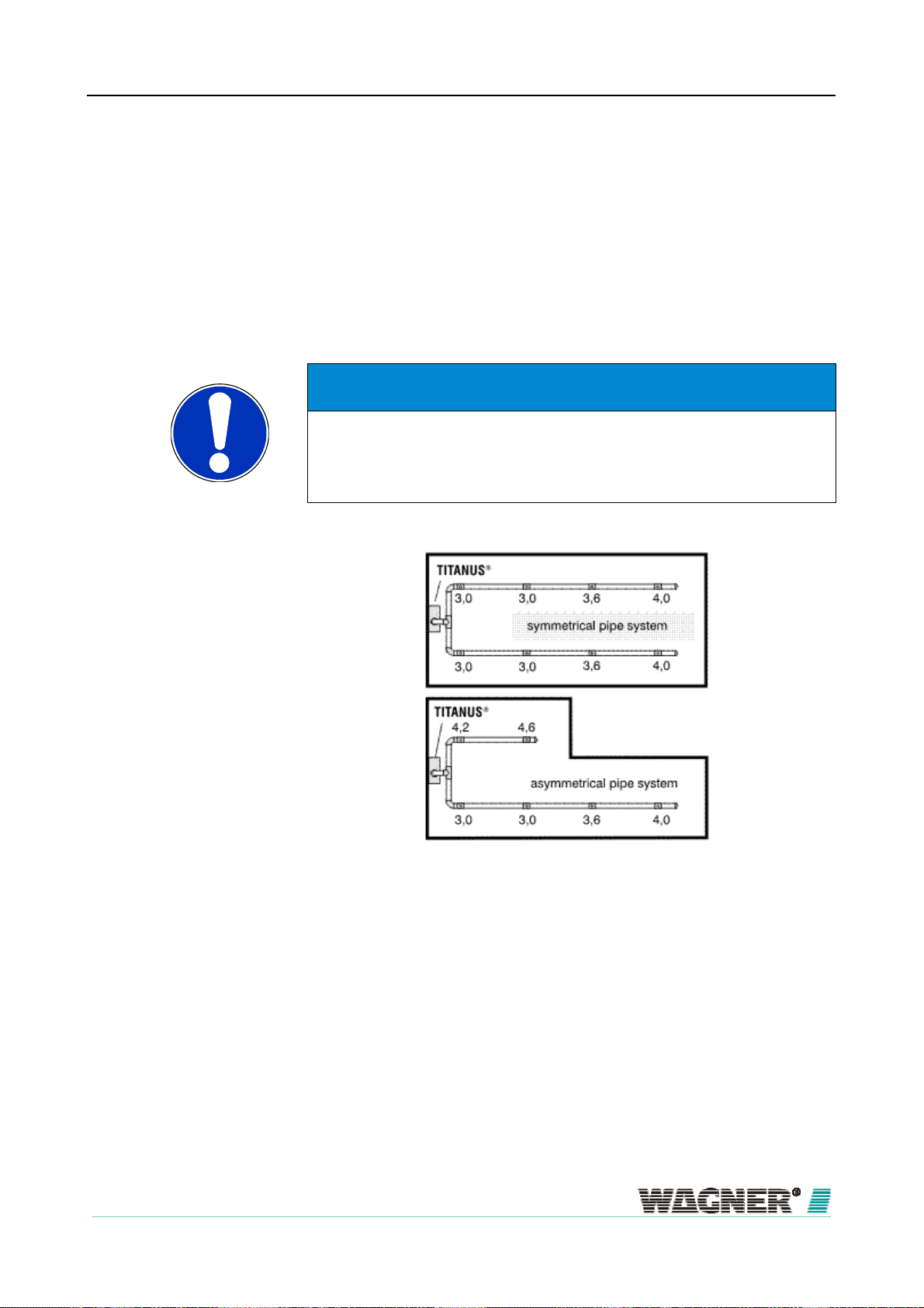
To insure equal air intake for all aspiration holes the following rules must be
obeyed:
▪ The length of the shortest and longest branch must not exceed a ratio of
1:2.
▪ The number of aspiration holes of the corresponding branches must not
exceed a ratio of 1:2.
▪ The aspiration holes should be evenly distributed on the corresponding
branches.
NOTICE
Each connected pipe system must comply with the design limits of TITA-
®
NUS
for the selected pipe design (please refer to chapter “Project Plan-
ning Limits”):
Figure 37: Example of a symmetrical and an asymmetrical U-pipe system
Figure „Example of a symmetrical and an asymmetrical U-pipe system” illus-
trates exemplary a U-shape pipe system with symmetrical and asymmetrical
pipe designs and according to chapter ´Standard Design´ the calculated di-
ameters of the aspiration holes. The diameters of the aspiration holes are
determined for each branch of the pipe system separately and are depend-
ent on the total number of aspiration holes of the respective branch. Please
refer to chapter “Hole diameters” for corresponding tables with hole diame-
ters.
06/13
63
Page 64

Design
Branch length
TITANUS
MICRO·SENS
®
In order to ensure a short transport time for the smoke fumes in the sampling
pipe and thus enable rapid detection, it is better to plan several shorter than
Pipe designs
a few long ones (preferably a U- or double U-pipe system).
4 types of pipe designs can be selected, depending on the cabinet geometry
(see Figure „Project planning“).
I-pipe An air sampling smoke detection pipe system without branches.
U-pipe An air sampling smoke detection pipe system which branches into 2
air sampling branches after the connection to the TITANUS MI-
CRO·SENS
®
.
M-pipe An air sampling smoke detection pipe system which branches into 3
air sampling branches after the connection to the TITANUS MI-
CRO·SENS
®
.
Double-U-pipe An air sampling smoke detection pipe system which branches into 4
air sampling branches after the connection to the TITANUS MI-
CRO·SENS
®
.
NOTICE
The design for fire location should be the I-pipe configuration.
64
06/13
Page 65

TITANUS
MICRO·SENS
®
Design
Figure 38: Pipe designs
Direction change
Change of direction in the pipe system can increase the flow resistance.
Light change of direction (e.g. with 90 ° pipe bends or air sampling hose) are
already approved as part of the project according to EN 54-20 or ISO 7240-
20 and need not be considered further.
If the pipe system includes 90 ° angles, the maximum overall length of the
pipe system will be reduced. In this case, a 90 °-angle corresponds to a
straight pipe length of about 1.5 m air sampling pipe.
06/13
65
Page 66

A
y
Design
Special cases
TITANUS
MICRO·SENS
NOTICE
Bends are to be preferred over angles. An excessive number of changes in
direction can change the detection time.
If the pipe system does not match the project planning guidelines described
here due to structural constraints. WAGNER should offer could provide indi-
®
Checking
vidual calculations for such a case.
Check detection reliability with activation tests in cases where use of the sys-
tem is critical. Also check whether an air flow rate is present at individual as-
piration apertures.
TIP
5.1.3
The fan voltage can be increased in order to reduce transport time. Make
sure that the current intake increases.
Air flow monitoring
EN 54-20 or ISO 7240-20 requires the recognition of a 20 percent change in
the air flow volume by the detector module’s air flow sensor system. The ac-
tivating threshold of the air flow sensor system has to be adjusted to ≤ 20 %
in order to achieve this. It is recommended to conduct an air pressure-
dependent air flow compensation for both of these settings.
Any threshold desired may be set with systems which do not require EN 54-
20 or ISO 7240-20 conformity.
Project planning for the air flow monitoring system in sampling pipes is car-
ried out while taking into consideration the respective national regulations for
djusting the
air flow sensitivit
each country.
The air flow sensor sensitivity must be adjusted to the application in ques-
tion. Breakage and stoppages must be detected reliability with low suscepti-
bility to malfunction.
The activating threshold and for this reason the sensitivity of the air flow
sensor is continuously adjustable from 10 – 50 %.
66
06/13
Page 67

r
A
TITANUS
MICRO·SENS
®
In conformity with EN 54-20
or ISO 7240-20
Triggering threshold 10 % 20 % 40 % 50 %
Sensitivity Very high High Medium Low
Design
TIP
Dynamic air flow senso
ir pressure differences
system
Limitations
It is recommended to always select the greatest possible level which is
permissible according to national standards.
The device’s air flow monitoring enables the system to detect both pipe
breakages outside the device and sudden obstruction in individual aspiration
apertures (e.g. in the event of sabotage to the pipe system). The dynamic air
flow sensor system has been activated via the diagnostics software; the fol-
lowing modifications have to be regarded.
The air flow monitoring may only be set, if:
▪ Project planning according to “Individual aperture monitoring” has been
carried out “(see Chap. 5.3.1 “Pipe project planning individual aperture
monitoring“),
▪ the air flow sensor has been compensated depending on the air pres-
sure (see Chap. 8.1.2 “Air pressure dependent air flow compensation“)
und
▪ No large air flow fluctuations occur.
The same air pressure must be present throughout the sampling pipe.
NOTICE
If the air sampling smoke detection system and pipe system are in areas
with different air pressure, the air sampled by the TITANUS
circulated in the pipe system pressure area (see Chapter “Air recircula-
tion”).
06/13
®
should be re-
67
Page 68

Design
NOTICE
TITANUS
MICRO·SENS
®
TITANUS
outside the areas to be monitored and without air return.
MICRO·SENS
®
with active location of the fire must be installed
NOTICE
ROOM·IDENT cannot be used in applications with varying or not consistent
air pressure levels. This is due to the fact, that under these conditions the
aspirated air needs to be returned to the monitored area. Since air return is
5.1.4
not allowed with ROOM·IDENT these applications cannot be served.
Sensitivity
According to EN 54-20 or ISO 7240-20, the sensitivity of a air sampling
smoke detection system can be divided into particular fire sensitivity classes.
These sensitivity classes describe particular example applications in which
the systems can be used. Permissible system project planning can be de-
termined for each classification according to Chapter 5.2.
Air sampling smoke detection systems with a higher sensitivity class accord-
ing to EN 54-20 or ISO 7240-20 also meet the requirements of the lower
classes.
Class Description Example application
A
B
C
Air sampling smoke
detector with very high
sensitivity
Air sampling smoke
detector with increased
sensitivity
Air sampling smoker
detector with standard
sensitivity
Very early detection:
Highly diluted smoke in air
conditioned IT areas
IT areas
Early detection:
Diluted smoke
in conventional
(cooled IT areas)
Standard detection:
Fire detection with
the benefits of air
sampling smoke detection systems
NOTICE
The fire sensitivity classes A, B and C can be achieved with each detector
module available, depending on the number of aspiration apertures.
68
06/13
Page 69

TITANUS
MICRO·SENS
®
The following sensitivities can be adjusted with the different detection units.
Sensitivity Sensitivity
Detection unit
DM-TM-10
Detection unit
DM-TM-50
0.1 - 2 % /m
0.5 - 2 % /m
Standard
0.1 % /m
0.5 % /m
Adjustment levels
Project planning for the monitored surface is always carried out according to
Design
0.1 % /m
0.1 % /m
5.1.5
national specifications for point-shaped smoke detectors.
Design Limits
The following limit values must always be observed with the TITANUS
CRO·SENS
®
:
MI-
▪ The minimum pipe length between 2 aspiration apertures is 0.1 m.
▪ The minimum pipe length between 2 aspiration apertures when locating
a fire is 3 m.
▪ The maximum pipe length between 2 aspiration apertures is 10 m.
▪ The maximum monitoring surface area per aspiration aperture corre-
sponds to the monitoring area of a point-specific alarm according to the
regulations in the particular national standards.
▪ Maximum 8 aspiration apertures are possible (Designs / design forms
not given in the manual are to be requested).
▪ Maximum 5 aspiration apertures are possible with site of a fire location.
The maximum overall monitoring surface area for the TITANUS
CRO·SENS
®
and the maximum overall pipe length depend on the design
MI-
chosen.
max. overall monitoring surface area per
TITANUS MICRO·SENS
400 m²
*Depending on the design chosen, restricted values apply in part.
NOTICE
Because of country-specific regulations, there may be restrictions com-
pared to the design limits in the manual!
06/13
®
max. design pipe length *
Pipe ∅ 25 mm: 50 m
plus
Pipe ∅ 12 mm: 8 x 3 m
69
Page 70

Design
TITANUS
MICRO·SENS
®
5.2
5.2.1
Project planning
Project planning guidelines
In order to conduct project planning in accordance with the EN 54-20 or ISO
7240-20 standard, it is necessary to be familiar with particular factors. These
are the requirements for the system’s sensitivity, the number of aspiration
apertures and the accessories necessary for the corresponding application.
The pipe system design in conformity with the standard can be determined
based on these factors using the following chapter and with the help of the
5.2.1.1
project planning tables in the appendix.
Determining the necessary accessories
Since the accessory components, such as filters, have a certain influence on
the dimension of the pipe planning, the suitable accessories must be se-
lected for the corresponding application ahead of time. Retrofitting, with a
fine filter, for instance, is generally only possible if a more sensitive detector
module is being used or a particular reserve has been planned in advance.
NOTICE
Components which have not been approved by WAGNER are used, CE
conformity on the basis of EN 54-20 or ISO 7240-20 will not be possible.
The following accessory components should be taken into consideration in
the process:
▪ Air filters
▪ Steam trap
▪ VSK stop valves
▪ Detector box
▪
OXY·SENS
The SD-1 noise suppressor and the steam trap KA-1 may be used in any
case with no project planning restrictions. configuration.
®
air sampling detector
70
06/13
Page 71

A
r
TITANUS
MICRO·SENS
®
Design
5.2.2
ir filters
Steam trap
Pipe accessories
Type Application Examples
LF-AD Coarse filter for separating
particles > approx. 15 µm
LF-AD-1 Filter for separating
particles > approx. 10 µm
LF-AD-2 Fine filter for separating
particles > approx. 5 µm
SF-400 Fine filter for separating
particles > approx. 1 µm
SF-650 Fine filter for separating
particles > approx. 1 µm
Type Application
Dust, insects, fibres,
hair, cinders, pollen
As above. Additionally:
Colour pigments and fine dust
As above. Additionally:
Fine dust in low concentrations
As above. Additionally:
Fine dust in high concentrations
As above, but with
increased filter lifetime
KA-DN-25 Condensation separator for applications with condensation moisture in
the pipe
KA-1 Condensation separator for applications with condensation moisture in
Sound suppresso
Stop valve
Typ Application
SD-1 Sound suppressor for areas sensitive to noise
Typ Application
the pipe
AVK-PV Stop valve for VSK cleaning air nozzle
AVK-PV-F Stop valve for VSK cleaning air nozzle for use in freezer areas
5.2.3
5.2.3.1
Sensitivity and pipeline project planning
Pipeline project planning with pipe accessories
The following project planning tables for pipeline project planning can be
found in the appendix for each previously selected pipe accessory.
▪ Project planning without filter
▪ Project planning with LF-AD air filter
▪ Project planning with LF-AD-1 air filter
▪ Project planning with LF-AD-2 air filter
▪ Project planning with SF-400 / SF-650 air filter
06/13
71
Page 72

Design
TITANUS
MICRO·SENS
NOTICE
An area can be monitored with more than detection points than required by
the national guideline in order to improve an air sampling smoke detection
system’s detection quality. In such case, the number of normatively re-
quired sampling points is to be used in calculating the required sensitivity of
an air sampling smoke detection system.
®
72
06/13
Page 73

TITANUS
MICRO·SENS
Procedure
®
In the following example, a project plan is supposed to fulfil class B require-
ments with air filters LF-AD-1, with 4 apertures and without further acces-
sory. The red arrows show the possible project plans with varying pipe
shapes and fan voltages.
1. Selection
Selection of the corresponding project planning table based on the air filter to be
used (see Chap. 5.2.2 )
Result
The project planning table has been determined
2. Selection
Selection of the number of aspiration apertures in the project planning table
Result
The achievable sensitivity class for the selected number of apertures has been
determined
3. Selection
Determinations on the sensitivity necessary to achieve the sensitivity class
Result
Determination of the detection unit and sensitivity setting
4. Selection
Selection of other pipe components ( e.g. steam trap see Chap. 5.2.2 described
components)
Result
The project planning table has been determined
5. Selection
Pipe length selection
Result
Determination of the pipe shape and necessary fan voltage
Design
06/13
73
Page 74

Design
TITANUS
MICRO·SENS
®
74
06/13
Page 75

TITANUS
MICRO·SENS
Results:
®
The following modules may optionally be used with the corresponding set-
tings for class B or A:
▪ Detection unit DM-TM-10 – with a sensitivity of 0.1 % LT/m to 0.6 %
LT/m
▪ Detection unit DM-TM-50 – with a sensitivity of 0.5 % LT/m to 0.6 %
LT/m
Possible system parameters:
▪ I- pipe system
– ≥ 9 V fan voltage, max. 40 m overall pipe length
▪ U- pipe system
– ≥ 9 V fan voltage, max. 50 m overall pipe length
▪ M- pipe system
– ≥ 9 V fan voltage, max. 50 m overall pipe length
Design
▪ Double U- pipe system
– ≥ 9 V fan voltage, max. 50 m overall pipe length
06/13
75
Page 76

A
A
Design
TITANUS
MICRO·SENS
®
5.2.4
Aperture diameter
The aperture diameters of the aspiration apertures can be found in the cor-
responding table for the respective pipe configuration:
I-pipe
Figure 39: I-pipe system
spiration apertures
Number of apertures 1 2 3 4 5
Aspiration aperture ∅ in mm*
6,8
A
—
B
—
C
—
D
—
E
5,0
5,0
—
—
—
4,2
4,2
4,4
—
—
3,4
3,6
3,8
4,4
—
3,0
3,2
3,4
3,6
4,4
*) Press cut diameter in aspiration-reducing film sheet
U-pipe
Figure 40: U-pipe system
spiration apertures
Number of apertures 2 4 6 8
Aspiration aperture ∅ in mm*
A
B
C
D
6,0
—
—
—
4,2
4,6
—
—
3,4
3,4
4,4
—
3,0
3,0
3,6
4,0
*) Press cut diameter in aspiration-reducing film sheet
76
06/13
Page 77
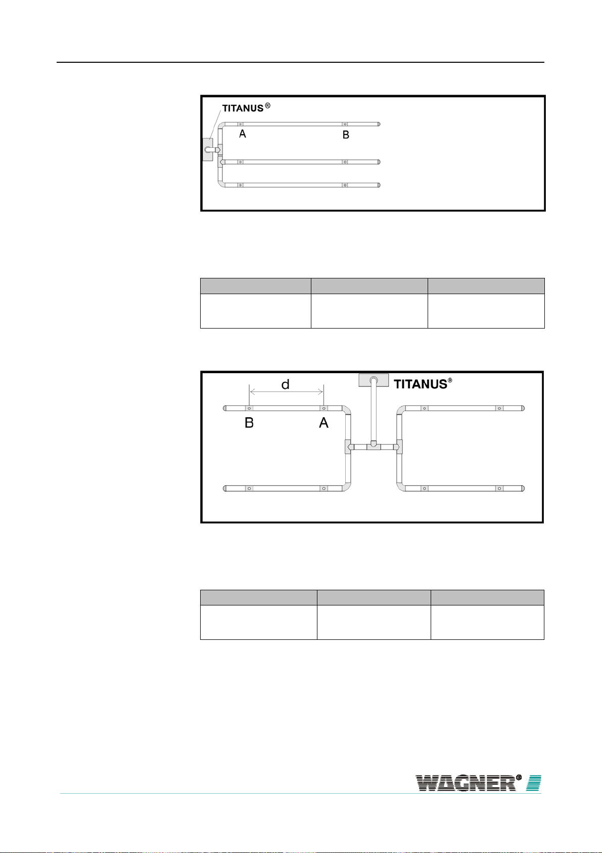
A
A
TITANUS
MICRO·SENS
M-pipe
®
Figure 41: M-pipe system
Design
spiration apertures
Number of apertures 3 6
Aspiration aperture ∅ in mm*
A
B
5,0
—
3,6
4,0
*) Press cut diameter in aspiration-reducing film sheet
Double U-pipe
Figure 42: Double U-pipe system
spiration apertures
Number of apertures 4 8
Aspiration aperture ∅ in mm*
A
B
4,4
—
3,0
3,8
*) Press cut diameter in aspiration-reducing film sheet
06/13
77
Page 78

A
Design
TITANUS
MICRO·SENS
®
5.3
5.3.1
Special project planning
Project planning for individual aperture monitoring
The following system parameters apply to the detection of an individual or a
particular number of blocked aspiration apertures, depending on pipe con-
figuration.
The specifications according to Chapter „Planning“ apply to project planning.
The following limit values and aperture diameters should also be taken into
account. Additional accessories (air filters, condensation separators, etc.)
5.3.1.1
can influence the maximum pipe length.
I-Pipe system
1 Pipe system
Figure 43: I-Pipe system for area protection
Limit values
min. distance TITANUS® – 1st aspiration aperture 2 m
max. distance TITANUS® – 1st aspiration aperture 20 m
max. overall pipe length per pipe system
pipe ∅ 25 mm plus
pipe ∅ 12 mm
max. overall pipe length per pipe system per
with high fan voltage 9,0 V
pipe ∅ 25 mm plus
pipe ∅ 12 mm
40 m
5 x 3 m
30 m
5 x 3m
min. distance between 2 aspiration apertures (d) 4 m
max. distance between 2 aspiration apertures (d) 10 m
spiration apertures
max. number aspiration apertures (n) per pipe system 5 no.
Number of apertures 1 2 3 4 5
Aspiration apertures ∅ in mm*
6,8
A
—
B
—
C
—
D
—
E
4,6
5,0
—
—
—
4,0
4,2
4,4
—
—
3,4
3,6
3,8
4,0
—
3,0
3,2
3,4
3,6
3,8
*) Press cut diameter in aspiration-reducing film sheet
78
06/13
Page 79
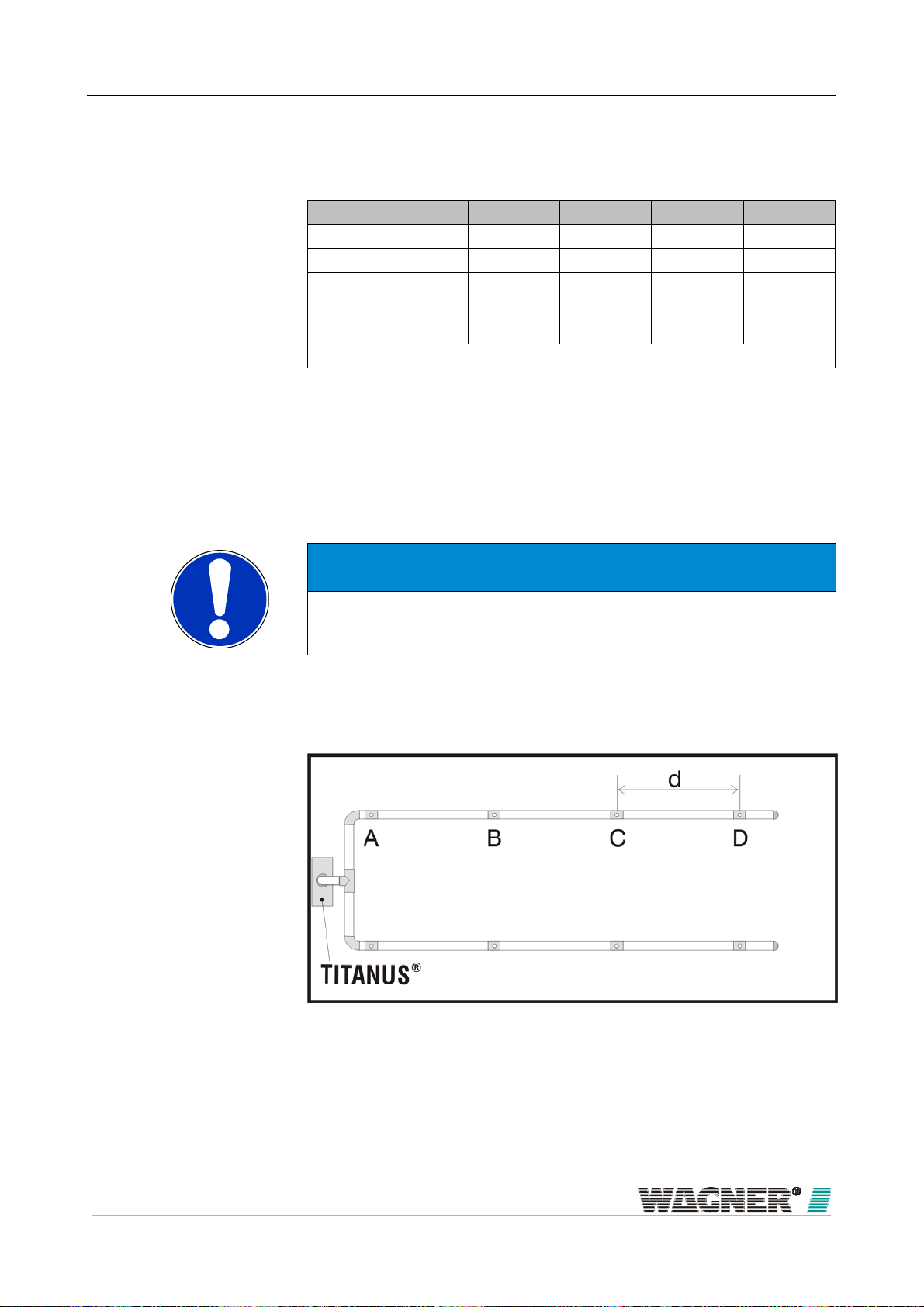
TITANUS
MICRO·SENS
®
Trigger Thresholds I-Pipe system
Number of apertures 2 3 4 5
1 blocked aperture ±25 % ±15 % ±10 % —
2 blocked apertures O O ±20 % ±15 %
3 blocked apertures O O O O
4 blocked apertures O O O O
5 blocked apertures O O O O
… is/are recognised when main air flow set x %
— not possible
Design
Example
O not purposeful
If the blockage of 2 aspiration apertures out of a total of 5 aspiration aper-
tures is recognised, then with the help of the diagnostics tool flow monitoring
can be set to ±15 %.
NOTICE
For a project planning according to EN 54-20 or ISO 7240-20, the air flow
monitoring has to be adjusted to ≤20 % in either case.
5.3.1.2
1 Pipe system
U-Pipe system
Figure 44: U-Pipe system for area protection
Limit values
06/13
79
Page 80

A
Design
spiration apertures
TITANUS
MICRO·SENS
min. distance TITANUS® – T piece 2 m
max. distance TITANUS® – T piece 20 m
max. branch length 25 m
max. overall pipe length per pipe system
Rohr ∅ 25 mm plus
pipe ∅ 12 mm
max. overall pipe length per pipe system per
with high fan voltage 9,0 V
pipe ∅ 25 mm plus
pipe ∅ 12 mm
50 m
8 x 3 m
40 m
8 x 3m
min. distance between 2 aspiration apertures (d) 4 m
max. distance between 2 aspiration apertures (d) 10 m
max. number aspiration apertures (n) per pipe system 8 Stück
Number of apertures 2 4 6 8
Aspiration apertures ∅ in mm*
A
B
C
D
6,0
—
—
—
4,2
4,4
—
—
3,4
3,6
3,6
—
*) Press cut diameter in aspiration-reducing film sheet
®
3,0
3,0
3,2
3,2
Trigger Thresholds U-Pipe system
Number of apertures 2 4 6 8
1 blocked aperture ±20 % ±10 % — —
2 blocked apertures O ±20 % ±15 % ±10 %
3 blocked apertures O O ±25 % ±20 %
4 blocked apertures O O O ±30 %
5 blocked apertures O O O O
6 blocked apertures O O O O
7 blocked apertures O O O O
Example
… is/are recognised when main air flow set x %
— not possible
O not purposeful
If the blockage of 3 aspiration apertures out of a total of 8 aspiration aper-
tures is recognised, then with the aid of the diagnostics tool, air flow monitor-
ing can be set to ±20 %.
NOTICE
For a project planning according to EN 54-20 or ISO 7240-20, the air flow
monitoring has to be adjusted to ≤20 % in either case.
80
06/13
Page 81

A
TITANUS
MICRO·SENS
®
Design
5.3.1.3
M-Pipe system
1 Pipe system
Figure 45: M-Pipe system for area protection
spiration apertures
Limit values
min. distance TITANUS® – T piece 2 m
max. distance TITANUS® – T piece 20 m
max. branch length 16.5 m
max. overall pipe length per pipe system
pipe ∅ 25 mm plus
pipe ∅ 12 mm
max. overall pipe length per pipe system per
with high fan voltage 9,0 V
pipe ∅ 25 mm plus
pipe ∅ 12 mm
50 m
8 x 3 m
40 m
6 x 3m
min. distance between 2 aspiration apertures (d) 4 m
max. distance between 2 aspiration apertures (d) 10 m
max. number aspiration apertures (n) per pipe system 6 no.
Number of apertures 3 6
Aspiration apertures ∅ in mm*
A
B
5,0
—
3,6
3,8
*) Press cut diameter in aspiration-reducing film sheet
Trigger Thresholds M-Pipe system
Number of apertures 2 6
1 blocked aperture ±25 % ±10 %
2 blocked apertures O ±25 %
3 blocked apertures O O
4 blocked apertures O O
5 blocked apertures O O
6 blocked apertures O O
06/13
… is/are recognised when main air flow set x %
81
Page 82

Design
Example
TITANUS
MICRO·SENS
O not purposeful
If the blockage of 1 aspiration apertures out of a total of 6 aspiration aper-
tures is recognised, then with the aid of the diagnostics tool, air flow monitor-
ing can be set to ±10 %.
NOTICE
For a project planning according to EN 54-20 or ISO 7240-20, the air flow
monitoring has to be adjusted to ≤20 % in either case.
®
5.3.1.4
Doppel-U-Pipe system
1 Pipe system
Figure 46: Double-U-Pipe system for area protection
Limit values
min. distance TITANUS® – T-no. 2 m
max. distance TITANUS® – T-no. 20 m
max. branch length 12.5 m
max. overall pipe length per pipe system
pipe ∅ 25 mm plus
pipe ∅ 12 mm
max. overall pipe length per pipe system per
with high fan voltage 9,0 V
pipe ∅ 25 mm plus
pipe ∅ 12 mm
min. distance between 2 aspiration apertures (d) 4 m
max. distance between 2 aspiration apertures (d) 10 m
max. number aspiration apertures (n) per pipe system 8 no.
50 m
8 x 3 m
40 m
8 x 3m
82
06/13
Page 83

A
TITANUS
MICRO·SENS
®
spiration apertures
Number of apertures 4 8
Aspiration apertures ∅ in mm*
A
B
4,4
—
*) Press cut diameter in aspiration-reducing film sheet
Trigger Thresholds double-U-pipe system
Number of apertures 2 6
1 blocked aperture ±10 % —
2 blocked apertures ±25 % ±10 %
3 blocked apertures O ±20 %
4 blocked apertures O ±30 %
5 blocked apertures O O
6 blocked apertures O O
… is/are recognised when main air flow set x %
— not possible
Design
3,0
3,2
O not purposeful
Example
If the blockage of 3 aspiration apertures out of a total of 8 aspiration aper-
tures is recognised, then with the aid of the diagnostics tool air flow monitor-
ing can be set to ±20 %.
NOTICE
For a project planning according to EN 54-20 or ISO 7240-20, the air flow
monitoring has to be adjusted to ≤20 % in either case.
06/13
83
Page 84

Design
TITANUS
MICRO·SENS
®
5.3.2
Simplified pipe design
Simplified pipe design is used for equipment protection and in areas with
small dimensions. The advantage of this design is the unified diameters of
the aspiration apertures.
For the project planning’s, the specifications according to chapter 5.2 apply.
Furthermore, the following limit values and opening diameters have to be
considered. Additional accessories (air filter, steam traps etc.) can influence
5.3.2.1
the maximum pipe length.
I-Pipe system
1 Pipe system
Figure 47: I-Pipe system, e.g. for equipment protection
Aspiration apertures
Limit values
min. distance TITANUS® – 1st aspiration aperture 2 m
max. distance TITANUS® – 1st aspiration aperture 20 m
max. overall pipe length per pipe system
pipe ∅ 25 mm plus
pipe ∅ 12 mm
max. overall pipe length per pipe system per
with high fan voltage 9,0 V
pipe ∅ 25 mm plus
pipe ∅ 12 mm
40 m
5 x 3 m
30 m
5 x 3m
max. number aspiration apertures (n) per pipe system 5 no.
min. distance between 2 aspiration apertures (d) 0.1 m
max. distance between 2 aspiration apertures (d) 4 m
minimum distance for fire site location between the aspiration
apertures (d)
3 m
Number of apertures 1 2 3 4 5
Aspiration apertures∅
in mm*
6,8
4,6
4,0
3,6
*) Press cut diameter in aspiration-reducing film sheet
3,4
84
06/13
Page 85

A
TITANUS
MICRO·SENS
®
Design
5.3.2.2
U-Pipe system
1 Pipe system
Figure 48: U-Pipe system, e.g. for equipment protection
spiration apertures
Limit values
min. distance TITANUS® – T piece 2 m
max. distance TITANUS® – T piece 20 m
max. branch length 25 m
max. overall pipe length per pipe system
pipe ∅ 25 mm plus
pipe ∅ 12 mm
max. overall pipe length per pipe system per
with high fan voltage 9,0 V
Rohr ∅ 25 mm plus
pipe ∅ 12 mm
50 m
8 x 3 m
40 m
8 x 3m
max. number of aspiration apertures (n) per pipe system 8 no.
min. distance between 2 aspiration apertures (d) 0.1 m
max. distance between 2 aspiration apertures (d) 4 m
Number of apertures 2 4 6 8
Aspiration apertures ∅
in mm*
6,0
4,2
3,4
*) Press cut diameter in aspiration-reducing film sheet
3,0
06/13
85
Page 86

A
Design
TITANUS
MICRO·SENS
®
5.3.2.3
M-Pipe system
1 Pipe system
Figure 49: M-Pipe system, e.g. for equipment protection
spiration apertures
Limit values
min. distance TITANUS® – T piece 2 m
max. distance TITANUS® – T piece 20 m
max. branch length 16.5 m
max. overall pipe length per pipe system
Rohr ∅ 25 mm plus
pipe ∅ 12 mm
max. overall pipe length per pipe system per
with high fan voltage 9,0 V
pipe ∅ 25 mm plus
pipe ∅ 12 mm
50 m
8 x 3 m
40 m
6 x 3m
max. number aspiration apertures (n) per pipe system 6 no.
min. distance between 2 aspiration apertures (d) 0.1 m
max. distance between 2 aspiration apertures (d) 4 m
Number of apertures 3 6
Aspiration apertures ∅
in mm*
5,0
3,6
*) Press cut diameter in aspiration-reducing film sheet
86
06/13
Page 87

A
TITANUS
MICRO·SENS
®
Design
5.3.2.4
Double U-pipe system
1 Pipe system
Figure 50: Double U-pipe system, e.g. for equipment protection
spiration apertures
Limit values
min. distance TITANUS® – T piece 2 m
max. distance TITANUS® – T piece 20 m
max. branch length 12.5 m
max. overall pipe length per pipe system
pipe ∅ 25 mm plus
pipe ∅ 12 mm
max. overall pipe length per pipe system per
with high fan voltage 9,0 V
pipe ∅ 25 mm plus
pipe ∅ 12 mm
50 m
8 x 3 m
40 m
8 x 3m
max. number aspiration apertures (n) per pipe system 8 no.
min. distance between 2 aspiration apertures (d) 0.1 m
max. distance between 2 aspiration apertures (d) 4 m
Number of apertures 4 8
Aspiration apertures ∅
in mm*
4,4
3,0
*) Press cut diameter in aspiration-reducing film sheet
06/13
87
Page 88

X
X
X
Design
TITANUS
MICRO·SENS
®
5.3.3
Project planning with branch pipe
Project planning with branch pipe are suitable for sampling points which are
located distantly from the main run of the pipe system.
I
krit.
.........
.........
I
krit.
Stich X
I
X Y
I
Stich Y
Y
A
Stich A
I
T
I
T
T
I
T
®
A
N
U
S
®
A
N
U
S
B
CE
A
B
Stich B
I
D
D
T
I
T
®
A
N
U
S
C
.........
AB
I
krit.
E
I
T
T
®
A
N
U
S
.........
AB
I
krit.
C
D
Figure 51: Project planning with branch pipe
The branch pipes must be projected in accordance to the figure (project
Y
Y
planning with branch pipes). The project planning of I-pipe described in the
88
06/13
Page 89

r
TITANUS
MICRO·SENS
®
figure must be copied to every single sampling branch of other pipe forms
(U, M, double-U pipe system).
Referring to the project planning with burs please notice that the “critical
Design
length” (l
)of a project planning does not exceed the maximum total length
krit.
of pipe respectively of branch (referring to U, M, double-U pipe system). The
critical length described the sampling point which is located most distantly
from TITANUS
®
.
Two aspiration apertures in total can be projected on each branch pipes at
which the minimal and maximum distance between the aspiration apertures
Opening diamete
must be respected.
The opening diameters are valid for the projected aspiration apertures in ac-
cordance with the chapter „Opening diameter for standard project planning“.
Figure 52: Distances of apertures with branch pipes
Distances of apertures
The distance between the T-piece and the following branch pipe as well as
Maximum length of branch
the pipe length between aspiration apertures on the branch pipes must not
exceed 12 m in total.
Figure 53: Maximum branch pipe
The length of pipe between the last T-piece and the last aspiration apertures
pipe
is the length of branch pipe. All other branch pipes need to be shorter. Two
aspiration apertures in total can be projected on each branch pipe.
06/13
89
Page 90

Design
TITANUS
MICRO·SENS
TIP
If the maximum distance is exceeded a correction by an additonal aspira-
®
tion aperture on a branch pipe can be done. In this connection please no-
tice that two aspiration apertures in total can be projected on each branch
pipe.
NOTICE
When the fire location (ROOM·IDENT) localization must only be one aspi-
ration aperture per branch pipe can are projected. At least 3m distance
must be maintained between the suction port of the first branch pipe and
each configured subsequent aspiration aperture.
Folgen
90
06/13
Page 91

r
A
TITANUS
MICRO·SENS
®
Design
5.3.4
Monitoring ai
conditioning ducts
Project design for forced air flow
Air conditioning plants are divided into low-speed and high-speed plants
(see table below). The information given in this chapter applies only to low-
speed plants. There is insufficient information from experience with high-
speed plants. Where air conditioning ducts have flow speeds of more than
10 m/s, therefore, smoke testing must be carried out for the best reaction
behavior to be determined.
Low-speed systems High-speed systems
Flow speed maximum 6 bis10 m/s > 10 m/s
Duct cross-section large small
Differential pressures
along the flow direction
small
large
The speed distribution in an air conditioning duct looks as follows:
Figure 54: Speed distribution in an air conditioning duct
spiration
Location of the pipe system
To achieve optimum detection results, the pipe system must be arranged in
the area v
to v3.
1
To achieve the best location for constructing the pipe system, the exhaust
duct should be as far as possible from sound dampers, air baffle plates and
kinks. The guideline figure for the distance from such “obstacles” is at least 3
x the smallest duct diameter.
If it is absolutely essential to fit the pipe system directly behind baffle plates,
sound dampers or bends, the main speed areas must be monitored.
06/13
91
Page 92

Design
Figure 55: Duct direction change without baffle plates
TITANUS
MICRO·SENS
®
Figure 56: Sound dampers in a duct
When a pipe system is built into air conditioning ducts, the following must be
observed:
▪ As the TITANUS
®
and the pipe system are in different pressure areas,
there must be an air return arrangement (see following page).
▪ The pipe entries into the duct must be sealed air-tight.
▪ The part of the pipe system which is outside the duct must be bonded
air-tight.
92
06/13
Page 93

r
A
t
TITANUS
MICRO·SENS
®
Design
Figure 57: Air return
The open end of the air return pipe is chamfered at an angle of 45°.
The distance between the aspiration apertures and between them and the
Bore distance
Sampling aperture
diamete
duct wall is shown in the following table.
Duct cross section
Distance from aspiration
apertures to the wall
Distance between the
aspiration apertures
≤ 0,5 m²
100 to 200 mm 200 to 300 mm
100 mm 150 mm
Duct cross section
> 0,5 m²
The diameter of the sampling aperture results from the number of aspiration
apertures. The precise value can be found in Chapter "Simplified pipeline
project planning”.
rrangemen
The pipe is concluded with an end cap without a bore.
The aspiration apertures should be arranged against the air flow.
During project planning, it is to be taken into account that the air conditioning
ducts for mounting the pipe system are often only accessible from two sides.
06/13
93
Page 94

Design
Example
TITANUS
MICRO·SENS
The following illustration depicts two project planning examples of pipe sys-
tems in air conditioning ducts.
®
Figure 58: Ducts with small and large duct cross-section
94
06/13
Page 95

TITANUS
MICRO·SENS
®
Design
5.3.5
Project design with air sampling hose
The application of an air sampling hose can be useful if several direction
changes on a short distance of a pipe system is required, e. g. for avoiding
any obstacles.
As the transport time can be manipulated negatively by application of an air
sampling hose, the influence of the used air sampling hose is to be deter-
mined on the allowed total length of pipe as follows.
Consideration during application of air sampling hose:
For calculation the maximum length of air sampling pipe with air sampling
hose, the length of the air sampling hose must be multiplied by the certain
factor b and deducted from the allowed total length of pipe.
Air sampling pipe length = Total pipe length – (Length of the air sampling hose * Factor
b)
Factor for calculation of the air sampling hoses length:
Air sampling hose Factor b
Type SCH-PG16 1,1
Type SCH-P25 0,5
Example 1: Altogether, the air sampling hose of type SCH-PG16 with a
length of 12 m shall be connected to a TITANUS
®
air sampling smoke de-
vice. The allowed total length of pipe is 50 m. The result for the maximum air
sampling pipe inclusive air sampling hose is:
Air sampling pipe length = 50 m - (12 m * 1,1) = 36,8 m
Example 2: In case of a pipe project planning, 45 m of air sampling pipe and
air sampling hose shall be connected to a TITANUS
®
air sampling smoke
device. In accordance to the project planning scale, the allowed total length
of pipe can be 50 m for the complete pipe project planning. The result for the
maximum length of the complete air sampling hose of type SCH-P25, which
can be integrated within the pipe project planning, after formula adjustment
is:
Length of the air sampling hose = (Total pipe length - Air sampling pipe lenght) / Factor
Length of the air sampling hose = (50 - 45 m) / 0,5 = 10 m
b
06/13
95
Page 96

Design
TITANUS
NOTICE
The complete air sampling pipe must not consist of a single air sampling
hose.
NOTICE
Aspiration reduction must not put about the air sampling hose.
MICRO·SENS
®
5.3.6
Project planning with air return
In some cases, in which differences of air pressure between the area of air
sampling device and the area of air sampling point exist, a channel of air
pressure of the aspirated test air in the pressure area of air sampling points
can be necessary. Therefore, an air sampling hose with a right length should
be connected on the air outlet of the air sampling device.
As the transport time of an air sampling smoke detection device can be ma-
nipulated negatively by an air return, the influence of the air return to the al-
lowed total length of pipe is to be respected.
An air return with a pipe with Ø 40 mm has no influence and can be pro-
jected and/or retrofitted without reducing the total pipe length and / or retrofit-
ted.
Consideration of air returns:
For calculation the maximum length of air sampling pipe, the length of the air
return must be multiplied by the certain factor a and deducted from the al-
lowed total length of pipe.
Air sampling pipe lenght = Total pipe length – (Length of the air return * Factor a)
96
Factors to calculate the lengths of air return (∅ 25 mm):
Length of the air return Factor a
0 bis 5 m 0,0
> 5 bis 10 m 1,6
> 10 bis 25 m 3,2
06/13
Page 97

TITANUS
MICRO·SENS
®
Factors to calculate the lengths of air return (∅ 32 mm):
Length of the air return Factor a
0 bis 5 m 0,0
> 5 bis 10 m 0,0
> 10 bis 25 m 1,0
Example: An air return (∅ 25 mm) from 10 m to be connected to a TITA-
®
NUS
. The allowed total length of pipe is 50 m. The result for the maximum
air sampling pipe is:
Air sampling pipe lenght = 50 m – (10 m * 1,6) = 48,4 m
Design
06/13
97
Page 98

InnInI
g
I
p
p
p
I
InI
p
q
Design
TITANUS
MICRO·SENS
®
5.4
Power supply
The alarm-ready status in the fire protection system and the aperture of an
alarm are taken into account when rating the external mains supply. In the
system's alarm-ready status, the mains supply must supply standby current
to the air sampling smoke detection systems and ensure that the emergency
power batteries are charging in accordance with DIN VDE 0833 Part 1 (80%
load in 24 hours).
NOTICE
The mains supply of the air sampling smoke detection systems shall be
approved according to EN 54-4.
Power calculation
Room protection
Equipment protection
The following formulae apply in case of alarm:
I
)(
)(
InnInII
powerquiescentalarmequipmenttotal
.max
.max,supmaxmax.,
plypowerareaquiescentareaalarmroomtotal
Charging current
The current for charging the accus is calculated by the following formula:
8,0
K
min
ch
arg
in
I
24
quiescentequipmenttotal
alno
owersu
max.y,
lcharging,
I
total
I
ower supply, max.
n = total number of all air sampling systems connected to a power
N
max. area
I
alarm
I
uiescent
K
nominal
I
charging
= total current of all connected air sampling systems [A]
= max. supply current of the power supply unit [A]
supply unit
= total number of all air sampling systems in the area with the
highest power consumption
= alarm current of an air sampling system [A]
= quiescent current of an air sampling system [A]
= nominal capacity of the accumulators [Ah]
= charging current of the accumulators (within 24 h 80% of the
nominal capacity) [A]
98
06/13
Page 99

I
TITANUS
MICRO·SENS
®
Design
NOTICE
The higher figure of the total current calculated (I
power supply!
) is used to design the
total
The power consumption of the TITANUS
Line calculation
cal Data".
The maximum line length results from the permitted line drop on the feed.
®
can be found in Chapter, "Techni-
The permitted line drop is the difference resulting from the stand-by accus
discharge voltage (21.5 V) and the lower operating voltage limit of the aspi-
ration smoke detection system.
total
AU
2
max
L
Lmax
A =
Itotal
γ
∆U
=
Maximum line length in [m]
Wire cross-section in [mm²]
=
Total current of the aspiration smoke detection system in [A]
=
Conductivity: Cu=57m/Ωmm²
=
Max.line drop on the feed
To guarantee the tightness of the housing seal, the appropriate cable
throughput for the particular cable must be selected.
▪ M 25- cable throughput: ∅ 9 to 14 mm
▪ M 20- cable throughput: ∅ 8 to 12 mm
Emergency Supply
Calculation
The nominal capacity is calculated by means of the following formula:
min
totalquiescentalno
25.1)5.0(
hItnIK
Knominal
t =
=
nominal capacity of the emergency supply accumulators [Ah]
required bridging time [h]
The factor 1.25 in the equation is only to be observed if bridging times are
smaller equal to [sic] 24 hours.
06/13
99
Page 100

 Loading...