

Page 1
Originalbetriebsanleitung
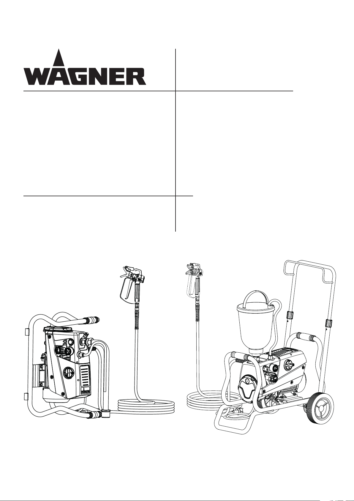
Airless – Hochdruck Spritzgerät
Airless high-pressure spraying unit
Appareil de pulvérisation à haute
pression Airless
Apparecchio di verniciatura a spruzzo
Airless ad alta pressione
Super Finish 23 PLUS
Betriebsanleitung 2
Operating manual 34
Mode d'emploi 65
Istruzioni per l‘uso 97
2334 424
2341576
07 / 2014
2334 444
Page 2

Super Finish 23 PLUS
Contents
1 SAFETY REGULATIONS FOR AIRLESS SPRAYING 36
1.1 Flash point _________________________________ 36
1.2 Explosion protection _________________________ 36
1.3 Danger of explosion and re from sources of
ignition during spraying work _________________ 36
1.4 Danger of injury from the spray jet _____________ 36
1.5 Secure spray gun against unintended operation __ 36
1.6 Recoil of spray gun __________________________ 36
1.7 Breathing equipment as protection against
solvent vapors ______________________________ 36
1.8 Prevention of occupational illnesses ____________ 36
1.9 Max. operating pressure ______________________ 37
1.10 High-pressure hose _________________________ 37
1.11 Electrostatic charging
(formation of sparks or ames) ________________ 37
1.12 Use of units on building sites and workshops _____ 37
1.13 Socket at the unit ___________________________ 37
1.14 Ventilation when spraying in rooms ____________ 37
1.15 Suction installations _________________________ 37
1.16 Earthing of the object ________________________ 37
1.17 Cleaning the unit with solvents ________________ 37
1.18 Cleaning the unit ___________________________ 37
1.19 Work or repairs at the electrical equipment ______ 37
1.20 Work at electrical components _________________ 38
1.21 Setup on an uneven surface ___________________ 38
GB
CONTENTS
4.6 Cleaning preserving agent when starting-up of
operation initially ___________________________ 42
4.7 Ventilate unit (hydraulic system) if the sound of
inlet valve is not audible ______________________ 42
4.8 Taking the unit into operation with
coating material ____________________________ 42
5 SPRAYING TECHNOLOGY ___________________ 44
6 HANDLING THE HIGHPRESSURE HOSE _______ 44
7 INTERRUPTION OF WORK ___________________ 44
8 CLEANING THE UNIT _______________________ 45
8.1 Cleaning the unit from the outside _____________ 46
8.2 Suction lter _______________________________ 46
8.3 High-pressure lter __________________________ 46
8.4 Cleaning the Airless spray gun _________________ 47
9 SERVICING ________________________________ 47
9.1 General servicing ___________________________ 47
9.2 High-pressure hose __________________________ 47
10 REPAIRS AT THE UNIT ______________________ 48
10.1 Inlet valve Pusher ___________________________ 48
10.2 Inlet valve _________________________________ 48
10.3 Outlet valve ________________________________ 49
10.4 Pressure control valve ________________________ 49
10.5 Replacing the power cable ___________________ 50
10.6 Typical wear parts ___________________________ 50
10.7 Connection diagram _________________________ 51
10.8 Remedy in case of faults ______________________ 52
2 GENERAL VIEW OF APPLICATION ____________ 38
2.1 Application ________________________________ 38
2.2 Coating material ____________________________ 38
2.2.1 Coating materials with sharp-edged additional
materials __________________________________ 38
2.2.2 Filtering ___________________________________ 39
3. DESCRIPTION OF UNIT _____________________ 39
3.1 Airless process ______________________________ 39
3.2 Functioning of the unit _______________________ 39
3.3 Explanatory diagram _________________________ 40
3.4 Transportation ______________________________ 40
3.5 Trolley backtting __________________________ 41
3.6 Technical data ______________________________ 41
4 STARTUP _________________________________ 42
4.1 Unit with suction system _____________________ 42
4.2 unit with upper hopper (5 litres) _______________ 42
4.3 high pressure hose and spray gun ______________ 42
4.4 Connection to the mains network ______________ 42
4.5 Socket on unit (not included in all models) _______ 43
11 SPARE PARTS AND ACCESSORIES ____________ 53
11.1 Super Finish 23 PLUS accessories _______________ 53
11.2 Spare parts list Super Finish 23 PLUS ___________ 58
11.3 Spare parts list high-pressure lter _____________ 60
11.4 Spare parts List Trolley _______________________ 60
11.5 Spare parts List frame ________________________ 61
11.6 Spare parts list suction system (rigid) ___________ 61
11.7 Spare parts list hopper 5l _____________________ 62
11.8 Spare parts list hopper with TopClean ___________ 62
Testing of the unit ________________________________ 63
Important information on product liability_____________ 63
Note on disposal __________________________________ 63
Guarantee declaration _____________________________ 63
CE - declaration__________________________________ 129
European service network _________________________ 132
35
Page 3
GB
SAFETY REGULATIONS
Super Finish 23 PLUS
1 SAFETY REGULATIONS FOR
AIRLESS SPRAYING
All local safety regulations in force must be observed.
The following sources are just a sample of those containing
safety requirements for Airless spraying.
a) The European Standard „Spray equipment for coating ma-
terials – safety regulations „ (EN 1953).
The following safety regulations are to be observed in order
to ensure safe handling of the Airless high-pressure spraying
unit.
1.1 FLASH POINT
Only spray coating materials with a ash point
of 21 °C or higher.
The ash point is the lowest temperature at
which vapors develop from the coating material. These vapors are sucient to form an
inammable mixture over the air above the
coating material.
1.4 DANGER OF INJURY FROM THE SPRAY JET
Attention, danger of injury by injection!
Never point the spray gun at yourself, other
persons or animals.
Never use the spray gun without spray jet
safety guard.
The spray jet must not come into contact
with any part of the body.
In working with Airless spray guns, the high
spray pressures arising can cause very dangerous injuries. If contact is made with the
spray jet, coating material can be injected
into the skin. Do not treat a spray injury as a
harmless cut. In case of injury to the skin by
coating material or solvents, consult a doctor
for quick and correct treatment. Inform the
doctor about the coating material or solvent
used.
1.5 SECURE SPRAY GUN AGAINST UNINTENDED
OPERATION
Always secure the spray gun when mounting or dismounting
the tip and in case of interruption to work.
1.2 EXPLOSION PROTECTION
Do not use the unit in work places which are
covered by the explosion protection regulations. The unit is not designed to be explosion protected. Do not operate the device in
explosive areas (zone 0, 1 and 2). Explosive areas are, for example, places where paints are
stored and locations in direct proximity to the
object being sprayed. Keep the device at least
3 m from the object you are spraying.
1.3 DANGER OF EXPLOSION AND FIRE FROM
SOURCES OF IGNITION DURING SPRAYING
WORK
There must be no sources of ignition such as,
for example, open res, lit cigarettes, cigars or
tobacco pipes, sparks, glowing wires, hot surfaces, etc. in the vicinity.
1.6 RECOIL OF SPRAY GUN
When using a high operating pressure, pulling the trigger guard can eect a recoil force
up to 15 N.
If you are not prepared for this, your hand can
be thrust backwards or your balance lost. This
can lead to injury.
1.7 BREATHING EQUIPMENT AS PROTECTION
AGAINST SOLVENT VAPORS
Wear breathing equipment during spraying work.
A breathing mask is to be made available to the user.
1.8 PREVENTION OF OCCUPATIONAL ILLNESSES
Protective clothing, gloves and possibly skin protection cream
are necessary for the protection of the skin.
Observe the regulations of the manufacturer concerning coating materials, solvents and cleaning agents in preparation,
processing and cleaning units.
36
Page 4

Super Finish 23 PLUS
GB
SAFETY REGULATIONS
1.9 MAX. OPERATING PRESSURE
The permissible operating pressure for the spray gun, spray
gun accessories, unit accessories and high-pressure hose
must not fall short of the maximum operating pressure of 25
MPa (250 bar or 3625 psi).
1.10 HIGHPRESSURE HOSE
Attention, danger of injury by injection! Wear
and tear and kinks as well as usage that is not
appropriate to the purpose of the device can
cause leakages to form in the high-pressure
hose. Liquid can be injected into the skin
through a leakage.
High-pressure hoses must be checked thoroughly before
they are used.
Replace any damaged high-pressure hose immediately.
Never repair defective high-pressure hoses yourself!
Avoid sharp bends and folds: the smallest bending radius
is about 20 cm.
Do not drive over the high-pressure hose. Protect against
sharp objects and edges.
Never pull on the high-pressure hose to move the device.
Do not twist the high-pressure hose.
Do not put the high-pressure hose into solvents. Use only
a wet cloth to wipe down the outside of the hose.
Lay the high-pressure hose in such a way as to ensure that
it cannot be tripped over.
Only use WAGNER original-high-pressure
hoses in order to ensure functionality, safety
and durability.
1.12 USE OF UNITS ON BUILDING SITES AND
WORKSHOPS
The unit may only be connected to the mains network via a
special feeding point with a residual-current device with INF
≤ 30 mA.
1.13 SOCKET AT THE UNIT
Do not load the socket with more than 1500 Watt. Unroll
any connected cable drum completely.
1.14 VENTILATION WHEN SPRAYING IN ROOMS
Adequate ventilation to ensure removal of the solvent vapors
has to be ensured.
1.15 SUCTION INSTALLATIONS
The are to be provided by the unit user in accordance with the
corresponding local regulations.
1.16 EARTHING OF THE OBJECT
The object to be coated must be earthed.
(Building walls are usually earthed naturally)
1.17 CLEANING THE UNIT WITH SOLVENTS
When cleaning the unit with solvents, the
solvent should never be sprayed or pumped
back into a container with a small opening
(bunghole). An explosive gas/air mixture can
arise. The container must be earthed.
1.11 ELECTROSTATIC CHARGING FORMATION OF
SPARKS OR FLAMES
Electrostatic charging of the unit may occur
during spraying due to the ow speed of
the coating material. These can cause sparks
and ames upon discharge. The unit must
therefore always be earthed via the electrical
system. The unit must be connected to an
appropriately-grounded safety outlet.
An electrostatic charging of spray guns and the high-pressure
hose is discharged through the high-pressure hose. For this
reason the electric resistance between the connections of the
high-pressure hose must be equal to or lower than 1 MΩ.
1.18 CLEANING THE UNIT
Danger of short-circuits caused by water ingression!
Never spray down the unit with high-pressure or high-pressure steam cleaners.
1.19 WORK OR REPAIRS AT THE ELECTRICAL
EQUIPMENT
These may only be carried out by a skilled electrician. No liability is assumed for incorrect installation.
37
Page 5

GB
SAFETY REGULATIONS
Super Finish 23 PLUS
1.20 WORK AT ELECTRICAL COMPONENTS
Unplug the power plug from the outlet before carrying out
any repair work.
1.21 SETUP ON AN UNEVEN SURFACE
The front end must always point downwards in order to avoid
sliding away.
If possible do not use the unit on an inclined surface since the
unit tends to wander through the resulting vibrations.
2 GENERAL VIEW OF APPLICATION
2.1 APPLICATION
Super Finish 23 PLUS is an electric driven unit for the airless
atomization of dierent painting materials. Also it is able to
feed the internal feeded paint roller, which is available as accessory.
Super Finish 23 PLUS is made for jobs in the workshop and on
the building site.
The unit performance is conceived so that its use is possible
on building sites for small- to middle-area dispersion work.
When painting, the device is suitable for all kinds of typical
painting jobs, e.g.:
doors, door frames, balustrades, furniture, woodencladding,
fences, radiators (heating) and steel parts.
We recommend using the top container for paintwork.
2.2 COATING MATERIAL
Diluting lacquers and paints or those containing solvents, twocomponent coating materials, dispersion and latex paints.
No other materials should be used for spraying without WAGNER‘s approval.
Pay attention to the Airless quality of the
coating materials to be processed.
The unit is able to process coating materials with up to
20,000 mPas. If highly viscous coating materials cannot be
taken in or the performance of the unit is to low, the paint
must be diluted in accordance with the manufacturer‘s instructions.
Attention: Make sure, when stirring up with
motor-driven agitators that no air bubbles
are stirred in. Air bubbles disturb when spraying and can, in fact, lead to interruption of
operation.
2.2.1 COATING MATERIALS WITH SHARPEDGED
ADDITIONAL MATERIALS
These particles have a strong wear and tear eect on valves
and tips, but also on the heating hose and spray gun. This impairs the durability of these wearing parts considerably.
38
Page 6

Super Finish 23 PLUS
GB
GENERAL VIEW OF APPLICATION
2.2.2 FILTERING
Sucient ltering is required for fault-free operation. To this
purpose the unit is equipped with a suction lter (Item 1) and
an insertion lter in the spray gun (Item 2). Regular inspection of these lters for damage or soiling is urgently recommended.
A high-pressure lter (Item 3) -available as accessory- is rising
up the ltering surface and will make the work more comfortable.
2
3
3.2 FUNCTIONING OF THE UNIT
The following section contains a brief description of the technical construction for better understanding of the function:
Super Finish 23 PLUS is an electrically driven high-pressure
paint spraying equipment.
The electric motor (1) drives the hydraulic pump via planetary
gears (2). A piston (3) is moved up and down so that hydraulic
oil is moved under the diaphragm (4) which then moves.
In detail:
The downwards movement of the machine opens the disk inlet valve (5) automatically and coating material is sucked in.
During the upwards movement of the diaphragm, the coating
material is displaced and the outlet valve opens while the inlet
valve is closed.
The coating material ows under high pressure through the
high-pressure hose to the spray gun and is atomized when it
exists from the tip.
The pressure control valve limits the set pressure in the hydraulic oil circuit and thus also the pressure of the coating
material.
A pressure change when the same tip is used also leads to a
change in the amount of paint atomized.
1
3. DESCRIPTION OF UNIT
3.1 AIRLESS PROCESS
The main area of application are thick layers of highly viscous
coating material.
At the Super Finish 23 PLUS unit a diaphragm pump takes in
the coating materials and transports it via a high-pressure
hose to the spray gun with the airless tip. Here the coating
material atomizes since it is pressed through the tip core at
a maximum pressure of 25 MPa (250 bar, 3625 psi). This high
pressure has the eect of micro ne atomisation of the coating material.
As no air is used in this process, it is described as an AIRLESS
process.
This method of spraying has the advantages of nest atomisation, cloudless operation (depending of a correct unit adjustment) and a smooth, bubblefree surface. As well as these, the
advantages of the speed of work and convenience must be
mentioned.
4
5
2
13
39
Page 7
GB
DESCRIPTION OF UNIT
Super Finish 23 PLUS
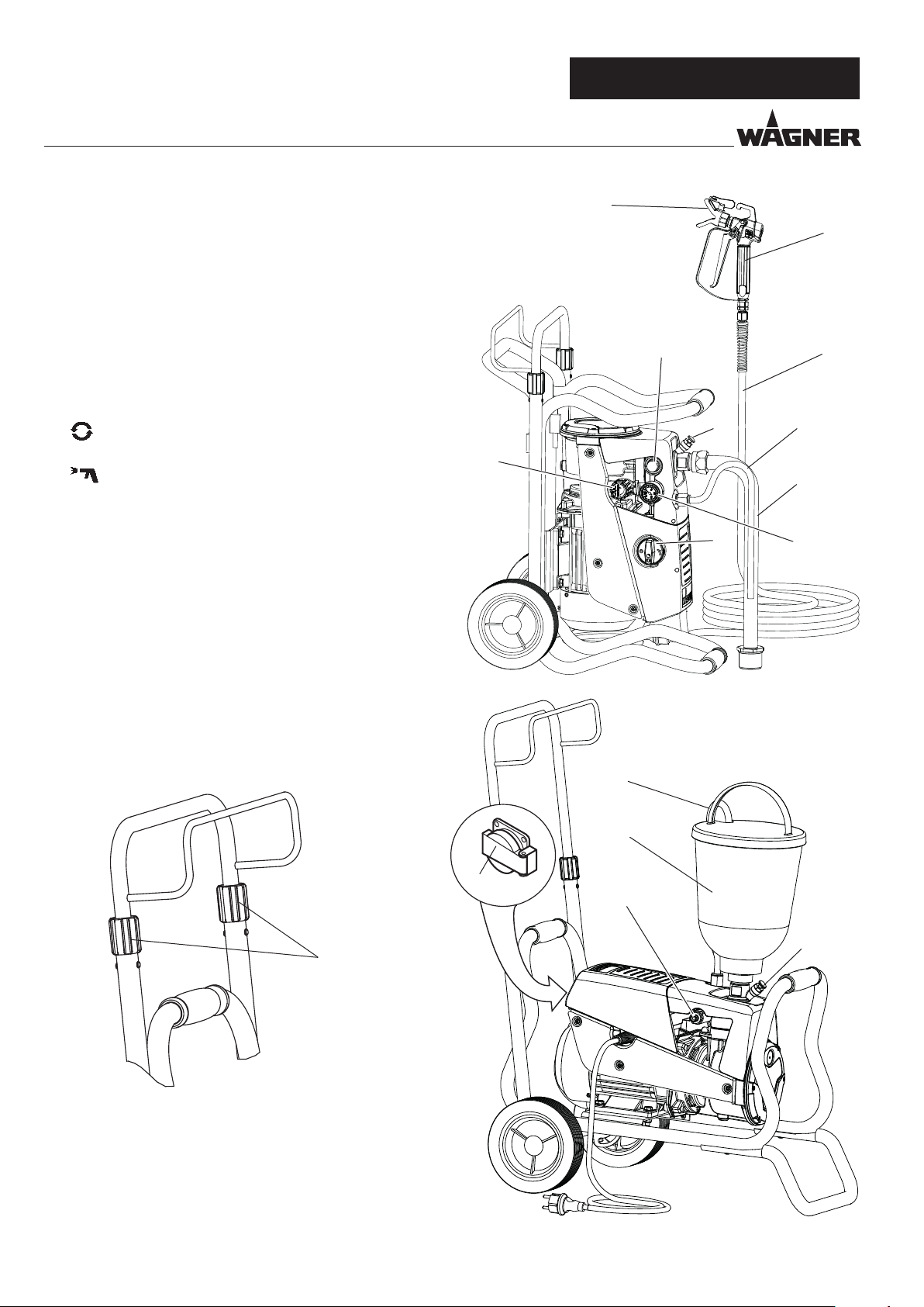
3.3 EXPLANATORY DIAGRAM
1 Tip guard with airless tip
2 Spray gun
3 High-pressure hose
4 Connection for high-pressure hose
5 Pressure gauge
6 Pressure control valve
7 Multifunction switch
Symbols (shown in the recess of the switch):
0 OFF
ON / Circulation
ON / Spraying
8 Return tube
9 Suction tube
10 Hopper
11 Inlet valve button
12 Outlet valve
13 Socket, max. load 1500 Watt
(not included in all models)
6
1
12
11
7
2
3
8
9
5
3.4 TRANSPORTATION
Unroll high-pressure hose and lay it over the shaft.
Loosen terminal sleeves (item 1) on the shaft ( open). Extract
shaft to the desired length. Tighten terminal sleeves again by
hand ( closed).
1
13
8
10
4
11
Transportation in vehicle
Secure the unit in the vehicle by means of suitable fasteners.
The device can be placed on its side if necessary. In this case,
please ensure that no attachments can be damaged. Attention: Paint or solvent residues can escape from the connections!
40
Page 8

Super Finish 23 PLUS
GB
DESCRIPTION OF UNIT
3.5 TROLLEY BACKFITTING
Before start with the backtting, pull of main
plug of socket, disassemble suction system
and high pressure hose
When changing between the top container and the suction
system, the carriage needs to be altered.
1. Unscrew the screws (pos. 1) with the attached wrench (17
mm).
2. Tilt the shaft and align the Super Finish 23 PLUS in the
required position:
a) Operate with suction system
b) Operate with top container
3. Re-tighten the screws.
1
3.6 TECHNICAL DATA
Voltage : 230 V AC, 50 Hz
Fuses : 16 A time-lag
Unit connecting line : 6 m long, 3 x 1.5 mm²
Max. current consumption: 7.4 A
Degree of protection : IP 44
Rated input of device: 1.3 kW
Max. operating pressure : 25 MPa (250 bar)
Max. volume ow : 2.6 l/min
Volume ow at 12 MPa
(120 bar) with water : 2.3 l/min
Max. temperature of the
coating material : 43 °C
Max. viscosity : 20,000 mPas
Empty weight
Model including carriage:
Model on frame:
Hydraulic oil lling
quantity :
Hydraulics housing
Gears
Plug connection on device (not
included in all models):
max. connection:
29 kg
24 kg
0.88 liter
0.05 liter
230 Volt ~, 50 Hz
1500 W
a) b)
Max. vibration at the spraygun : lower than 2.5 m/s²
Max. sound pressure level: 74 dB (A)*
*Place of measurement: 1 m distance from unit and 1.60
m above oor, 12 MPa (120 bar) operating pressure,
reverberant oor
41
Page 9

GB
STARTUP
Super Finish 23 PLUS
4 STARTUP
4.1 UNIT WITH SUCTION SYSTEM
1. Ensure that the sealing surfaces of the connections are
clean.
Ensure that the red inlet (1) is inserted in the coating ma-
terial inlet (4).
2. Use the enclosed 41 mm wrench to screw the union nut
(2) at the suction hose (3) onto the coating material inlet
(4) and tighten it.
3. Screw the union nut (5) at the return hose (6) to the connection (7) (22mm).
4.2 UNIT WITH UPPER HOPPER 5 LITRES
1. Ensure that the sealing surfaces of the connections are
clean. Ensure that the red inlet (1) is inserted in the coating material inlet (4).
2. Screw the union nut (5) on the return pipe (6) onto the
connection (7).
3. Screw the upper hopper (8) onto the coating material inlet (4).
if using hopper with cleaning ring (TopClean) step 4 and 5
4. Fix TopClean on hopper upside
5. Plug in return pipe into TopClean and screw on union nut
4.3 HIGH PRESSURE HOSE AND SPRAY GUN
1. Screw the high pressure hose (9) onto the hose connection
2. Screw the spray gun (10) onto the high pressure hose
3. Tighten all union nuts on high pressure hose so that no
coating material can escape.
4. Screw the tip holder with the selected tip onto the spray
gun, align tip and tighten union nut.
When unscrewing the high pressure hose,
hold rmly on the hose connection with a
22mm wrench.
4.4 CONNECTION TO THE MAINS NETWORK
Connection must always be carried out via
an appropriately grounded safety outlet with
residual-current-operated circuit-breaker.
Before connecting the unit to the mains supply, ensure that
the line voltage matches that specied on the unit’s rating
plate.
10
8
6
9
1
14
5
2
9
4
7
3
5
67
42
Page 10
Super Finish 23 PLUS
4.5 SOCKET ON UNIT
NOT INCLUDED IN ALL MODELS
It is possible, for example, to connect an agitator, a working
lamp etc with a maximum of 1500 Watt.
GB
STARTUP
3
Always switch on the Super Finish 23 PLUS
unit rst and then the connected unit. Otherwise the fuse protection of 16 A inside the
unit will react.
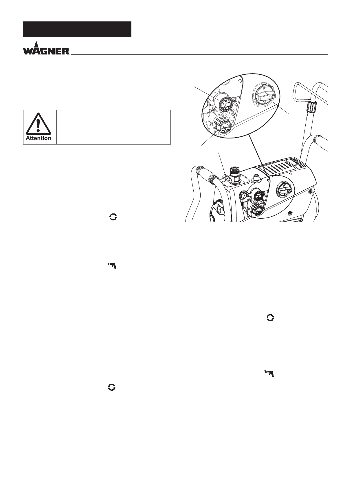
4.6 CLEANING PRESERVING AGENT WHEN
STARTINGUP OF OPERATION INITIALLY
Unit with suction tube
1. Immerse the suction system into a container lled with a
suitable cleaning agent (recommendation: water).
Unit with hopper
2. Fill up hopper with a suitable cleaning agent (recommendation: water).
3. Set multifunction switch (1) to (ON– circulation); the
unit commences to run.
4. Turn the pressure regulating knob (2) to the right until
the stop is reached.
5. Wait until cleaning agent is emitted from the return hose.
6. Turn the pressure regulating knob (2) back approx. one
rotation.
7. Set multifunction switch (1) to (spray).
Pressure is rising up inside the high pressure hose (visible
at pressure gauge)
8. Point the tip of the spray gun into an open collecting container and pull the trigger guard at the spray gun.
9. The pressure is increased by turning the pressure regulating knob (2) to the right. Set approx. 10 MPa (100 bar) at
the pressure gauge.
10. Spray the cleaning agent out of the unit for approx.
1 - 2 min. (~5 litres) into the open collecting container.
4.7 VENTILATE UNIT HYDRAULIC SYSTEM IF THE
SOUND OF INLET VALVE IS NOT AUDIBLE
1. Switch on the unit.
2. Turn pressure regulating knob (2) three revolutions to
the left.
3. Set multifunction switch (1) to (ON – circulation). The
hydraulic system is ventilated. Leave the unit on for two to
three minutes.
4. Then turn pressure regulating knob (2) to the right until
stop.
5. Press inlet valve pusher (4).
Sound of the inlet valve is audible.
6. If not, repeat points 2 and 4
1
2
4
4.8 TAKING THE UNIT INTO OPERATION WITH
COATING MATERIAL
Unit with suction tube
1. Immerse the suction system into a container lled with
coating material.
Unit with hopper
2. Fill coating material into the hopper.
3. Press inlet valve pusher (4) several times to release possibly clogged inlet valve
4. Set multifunction switch (1) to (ON - circulation); the
unit will start.
5. Turn the pressure regulating knob (2) to the right until
the stop is reached.
When the noise of the valves changes, the unit is bled and
takes in coating material.
6. If coating material exits from the return hose, turn the
pressure regulating knob (2) back approx. 1 rotation.
7. Set multifunction switch (1) to (spray).
Pressure is rising up inside the high pressure hose (visible
at pressure gauge (3)).
8. Pull of the spray gun and spray into an open collecting
container in order to remove the remaining cleaning
agent from the unit. When coating materials exits from
the tip, close the spray gun.
9. Adjust the spraying pressure by turning the pressure regulating knob (2).
10. The unit is ready to spray.
43
Page 11

GB
SPRAYING TECHNIQUE / HANDLING THE HIGH-PRESSURE HOSE / INTERRUPTION OF WORK
Super Finish 23 PLUS
5 SPRAYING TECHNOLOGY
Move the spray gun evenly during the spraying process. If this
is not observed, an irregular spraying appearance will be the
result. Carry out the movement with the arm, not with the
wrist. A parallel distance of approx. 30 cm between the tip and
the surface to be coated should always be observed. The lateral limitation of the spray fan should not to be too distinct.
The edge of spraying should be gradual to facilitate overlapping of the next coat. The spray gun should always be held at
an angle of 90° to the surface to be coated. A spray fan aimed
obliquely at the surface to be coated leads to an unwanted
spray cloud.
To achieve perfect surfaces at varnishing works, special accessories are available at Wagner, e.g. FineFinish tips or an AirCoat
gun set. Your Wagner dealer will advise you.
6 HANDLING THE HIGHPRESSURE
HOSE
The unit is equipped with a high-pressure hose specially suited for diaphragm pumps.
Danger of injury through leaking highpressure hose. Replace any damaged highpressure hose immediately.
Never repair defective high-pressure hoses
yourself!
The high-pressure hose is to be handled with care. Avoid sharp
bends and folds: the smallest bending radius is about 20 cm.
Do not drive over the high-pressure hose. Protect against
sharp objects and edges.
Never pull on the high-pressure hose to move the device.
Make sure that the high-pressure hose cannot twist. This can
be avoided by using a Wagner spray gun with a swivel joint
and a hose system.
When using the high-pressure hose while
working on scaolding, it is best to always
guide the hose along the outside of the scaffolding.
7 INTERRUPTION OF WORK
1. Switch o unit, set multifunction switch to (pressure
relief, circulation), then to 0 (OFF).
2. Pull trigger guard of spray gun to decrease the pressure of
the high pressure hose and the spray gun.
3. Secure the spray gun, refer to the operating manual of the
spray gun.
4. Remove tip from tip holder and store the tip in a small vessel with suitable cleaning agent.
5. Leave the suction system immersed in the coating material or immerse it in the corresponding cleaning agent.
The suction lter and unit should not dry out.
6. Cover the material container in order to prevent the paint
from drying.
In using quick-drying or two-component
coating materials, do not fail to rinse unit
through with a suitable cleaning agent during the processing period.
44
The risk of damage rises with the age of the
high-pressure hose.
Wagner recommends replacing high-pressure hoses after 6 years.
Only use WAGNER original-high-pressure
hoses with internal heating in order to ensure
functionality, safety and durability.
Page 12

Super Finish 23 PLUS
GB
DISPLAYS AT THE UNIT / CLEANING THE UNIT
8 CLEANING THE UNIT
A clean state is the best method of ensuring operation without problems. After you have nished spraying, clean the unit.
Under no circumstances may coating material rests dry and
harden in the unit. The cleaning agent used for cleaning (only
with a ash point above 21 °C) must be suitable for the coating material used.
• Secure the spray gun, refer to the operating manual of
the spray gun.
Remove and clean the tip.
• Unit with suction system
1. Set multifunction switch to (ON - circulation).
2. Remove suction tube from the material container, the return tube remains over the material container.
3. Immerse the suction system into a container lled with a
suitable cleaning agent
4. Turn the pressure control valve back in order to set a minimal spraying pressure.
5. Set multifunction switch to (spray).
6. Pull the trigger guard of the spray gun in order to pump
the remaining coating material from the suction hose,
high-pressure hose and the spray gun into an open container (if appropriate, increase the pressure at the pressure
control valve slowly in order to obtain a higher material
ow).
The container must be earthed in case of
coating materials which contain solvents.
Caution! Do not pump or spray in container
with small opening (bunghole)!
See safety regulations.
Warm water improves the cleaning eect in
the case of water-dilutable coating materials.
• Unit with upper hopper
1. Set multifunction switch to (ON - circulation).
2. Turn the pressure control valve back in order to set a minimal spraying pressure.
3. Set multifunction switch to (spray).
4. Pull the trigger guard of the spray gun in order to pump
the remaining coating material from the hopper, highpressure hose and the spray gun into an open container (if
appropriate, increase the pressure at the pressure control
valve slowly in order to obtain a higher material ow).
The container must be earthed in case of
coating materials which contain solvents.
Caution! Do not pump or spray in container
with small opening (bunghole)!
See safety regulations.
5. Fill up hopper with suitable cleaning agent.
6. Set multifunction switch to (ON - circulation).
7. Pump suitable cleaning agent in the circuit for several
minutes.
with cleaning ring (TopClean) step 8 up to 12
8. Switch reverser knob into a horizontal position.
The cleaning agent will ow around the circumference of
the inner hopper wall and will clean it in some minutes,
depending of the fouling
9. Switch reverser knob into the upright position.
Cleaning agent is owing directly into the hopper
7. Set multifunction switch to (ON - circulation).
8. Pump suitable cleaning agent in the circuit for several
minutes.
The cleaning eect is increased by alternatively opening and closing the spray gun.
9. Set multifunction switch to (spray).
10. Pump the remaining cleaning agent into an open container until the pump is empty.
11. Switch o the unit
Do not switch the reverser knob at the cleaning ring into the horizontal position when
the pump is loaded with coating material.
The holes could be plugged.
As a result the cleaning function will be reduced, as the cleaning ring has to clean itself
rst.
10. Set multifunction switch to (spray).
11. Pump the remaining cleaning agent from the hopper,
high-pressure hose and the spray gun into an open container
12. Set multifunction switch to (ON - circulation).
13. Switch o unit
45
Page 13

GB
CLEANING THE UNIT
Super Finish 23 PLUS
8.1 CLEANING THE UNIT FROM THE OUTSIDE
First unplug the power plug from the outlet.
Danger of short-circuits caused by water
ingression! Never spray down the unit with
high-pressure or high-pressure steam cleaners.
Do not put the high-pressure hose into solvents. Use only a wet cloth to wipe down the
outside of the hose.
Wipe down unit externally with a cloth which has been immersed in a suitable cleaning agent.
8.2 SUCTION FILTER
Clean lters always ensure maximum volume,
constant spray pressure and problem-free
functioning of the unit.
8.3 HIGHPRESSURE FILTER
1. Switch o unit – set multifunction switch to 0 (OFF).
2. Open the high-pressure lter and clean the lter insert. To
do so:
3. Unscrew the lter housing (1) by hand.
4. Remove the lter insert (2) and pull out the bearing spring
(3).
5. Clean all the parts with the corresponding cleaning agent.
If compressed air is available – blow through the lter insert and bearing spring.
6. When mounting the lter ensure that the bearing ring (4)
in the lter insert is positioned correctly and check the Oring at the lter housing for damage.
7. Screw on the lter housing by hand until it stops (a higher
tightening force only impedes later dismantling).
2
1
suction tube 5l hopper
Unit with suction system
1. Unscrew the lter (Item 1) from the suction tube.
2. Clean or replace the lter.
Carry out cleaning with a hard brush and a corresponding
cleaning agent.
Unit with hopper
1. Release screws with a screwdriver (Item 2).
2. Lift and remove lter disk with a screwdriver
3. Clean or replace the lter disk.
Carry out cleaning with a hard brush and a corresponding
cleaning agent.
46
Page 14

Super Finish 23 PLUS
GB
CLEANING THE UNIT / SERVICING
8.4 CLEANING THE AIRLESS SPRAY GUN
1. Rinse the Airless spray gun with a suitable cleaning agent
under lower operating pressure.
2. Clean the tip thoroughly with a suitable cleaning agent so
that no suitable coating material rests remain.
3. Do not store the tip in solvent because this reduces the
durability considerably.
4. Clean the outside of the Airless spray gun thoroughly.
1
3
9 SERVICING
9.1 GENERAL SERVICING
We strongly recommend having an annual
check carried out by technicians for safety
reasons. Please observe all the applicable national regulations.
You can servicing of the unit carried out by
the Wagner Service. Favourable conditions
can be agreed with a service agreement and/
or maintenance packages.
Minimum check before every startup:
1. Check the high-pressure hose, spray gun with rotary joint,
power supply cable with plug for damage.
2. Check whether the pressure gauge can be read.
Check at periodical intervals:
2
Insertion lter in the Airless spray gun
Removal
1. Pull the protective bracket (1) forwards.
2. Screw the grip (2) out of the gun housing. Pull out the insertion lter (3).
3. If the insertion lter is clogged or defective, replace it.
Installation
1. Slide the insertion lter (3) with the longer cone into the
gun housing.
2. Screw the grip (2) into the gun housing and tighten it.
3. Latch in the protective bracket (1).
1. Check inlet and outlet valve according wear. Clean it and
replace worn out parts.
2. Check all lter inserts (spray gun, suction system) clean it
and replace if necessary.
9.2 HIGHPRESSURE HOSE
Inspect the high-pressure hose visually for any notches or
bulges, in particular at the transition in the ttings. It must be
possible to turn the union nuts freely. A conductivity of less
than
1 MΩ must exist across the entire length.
Have all the electric tests carried by the Wagner Service.
The risk of damage rises with the age of the
high-pressure hose.
Wagner recommends replacing high-pressure hoses after 6 years.
47
Page 15

GB
REPAIRS AT THE UNIT
Super Finish 23 PLUS
10 REPAIRS AT THE UNIT
Switch the unit o.
Before all repair work: Unplug the power
plug from the outlet.
10.1 INLET VALVE PUSHER
1. Use a 17 mm spanner to screw out the inlet valve button.
2. Replace the wiper (1) and O-ring (2).
12
Installation
1. Insert the inlet valve (2) into the trigger housing (1) and
secure with the clasp (3). Ensure that the (black) seal (5) is
mounted in the trigger housing.
2. Screw the unit from the trigger housing and the inlet valve
into the paint section. The same (black) seal (6) has to be
mounted in the paint section.
3. Tighten the trigger housing with the 30 mm wrench and
tighten with three light blows of the hammer on the end
of the wrench. (Corresponds to approx. 90 Nm tightening
torque).
1
3
5
2
10.2 INLET VALVE
1. Place the enclosed 30 mm wrench on the trigger housing
(1).
2. Loosen the trigger housing (1) with light blows of a hammer on the end of the wrench.
3. Screw out the trigger housing with the inlet valve (2) from
the paint section.
4. Pull of the clasp (3) using the enclosed screwdriver.
5. Place the enclosed 30 mm wrench on the inlet valve (2).
Turn out the inlet valve carefully.
6. Clean the valve seat (4) with a cleaning agent and brush
(ensure that no brush hairs are left behind).
7. Clean the seals (5, 6) and check for damage. Replace, if
necessary.
8. Check all the valve parts for damage. In case of visible
wear replace the inlet valve.
4
6
48
Page 16

Super Finish 23 PLUS
GB
REPAIRS AT THE UNIT
10.3 OUTLET VALVE
1. Use a 22 mm wrench to screw the outlet valve from the
paint section.
2. Carefully pull of the clasp (1) using the enclosed screwdriver. The compression spring (2) presses ball (4) and
valve seat (5) out.
3. Clean or replace the components.
4. Check the O-ring (7) for damage.
5. Check the installation position when mounting the spring
support ring (3) (clipped onto spring (2)), outlet valve seat
(5) and seal (6), refer to gure.
1
6
2
5
4
3
7
10.4 PRESSURE CONTROL VALVE
Only have the pressure control valve (1) replaced by the customer service.
The max. operating pressure has to be reset
by the customer service.
1
49
Page 17

GB
REPAIRS AT THE UNIT
Super Finish 23 PLUS
10.5 REPLACING THE POWER CABLE
This may only be carried out by a skilled electrician. No liability is assumed for incorrect
installation.
Switch the unit o.
Before all repair work: Unplug the power
plug from the outlet.
1. In models with a front cover unscrew the trigger housing
with inlet valve (1) from the paint section (see inlet valve,
10.2, sections 1 to 3) and remove the front cover (2) by
unscrewing the screws.
2. Remove the multi-function switch (3) by unscrewing the
screws.
3. Remove the rear cover (4) by loosening the screws.
4. Loosen the cable threaded joint (5).
5. Loosen the wires in the mains terminal (6).
6. Replace the unit connecting line.
(only an approved power cable with the designation H07-
RNF with a splash-proof plug may be used).
7. Connect the green/yellow wire to the contact with the PE
sign.
8. Remount the covers carefully (do not squeeze any cables!)
9. Screw the trigger housing back into place (see inlet valve,
10.2, sections 3)
1
2
4
10.6 TYPICAL WEAR PARTS
Despite the use of high-quality materials the highly abrasive
eect of the paints means that wear can occur at the following parts:
Inlet valve (spare part Order No.: 0344700)
For replacing refer to Section 10.2
(failure becomes noticeable through performance loss and/or
poor or no suction)
Outlet valve (spare part Order No.: 0341702)
For replacing refer to Section 10.3
(failure becomes noticeable through performance loss and/
or poor suction) The outlet valve is usually considerably more
durable than the inlet valve. Thorough cleaning may already
help here.
3
5
6
50
Page 18

Super Finish 23 PLUS
10.7 CONNECTION DIAGRAM
A SUPER FINISH 23 PLUS WITH SOCKET
CONTROLER BOARD
brown
blue
GB
REPAIRS AT THE UNIT
red
NC NO
COM
MICRO SWITCH
black
red
yellow
MOTOR
WITH TEMPERATURE SWITCH
light blue
light blue
green/yellow
155°C
Z1
U1
1~
M
blue
green/yellow
L
N
U2
Z2
black
black
blue
C = 25µF
400V
OPERATION CAPACITOR
black
blue
TERMINAL STRIP
green/yellow
POWER CABLE
230V / 50Hz
blue
brown
POWER SOCKET
230V/50Hz max. 1500W
green/yellow
51
Page 19

GB
REPAIRS AT THE UNIT
B SUPER FINISH 23 PLUS
CONTROLER BOARD
brown
blue
NC NO
Super Finish 23 PLUS
red
yellow
COM
MICRO SWITCH
black
red
MOTOR
WITH TEMPERATURE SWITCH
light blue
light blue
green/yellow
155°C
U1
M
Z1
1~
blue
Z2
U2
black
blue
C = 25µF
400V
OPERATION CAPACITOR
52
POWER CABLE
230V / 50Hz
green/yellow
brown
Page 20

Super Finish 23 PLUS
REPAIRS AT THE UNIT
10.8 REMEDY IN CASE OF FAULTS
TYPE OF MALFUNCTION WHAT ELSE? POSSIBLE CAUSE MEASURES FOR ELIMINATING THE MALFUNCTION
Unit does not start Multifunction switch
can not switched on
Unit does not suck in Air bubbles do not exit
at the return hose
Air bubbles exit from
the return hose
Unit does not generate pressure
Unit has sucked in Air in the oil circuit Bleed the oil circuit in the unit by turning the
Unit reached pressure, but the pressure
collapses, also at the
pressure gage, during
spraying.
Unit reached pressure,
but the pressure collapses during spraying.
pressure gage still
shows high pressure
No voltage applied Check voltage supply
Unit fuse has triggered Let the motor cool down
Multi-function switch not
set back previously to „0“
Inlet valve clogged Press the inlet valve button until the stop is
Inlet/outlet valve soiled
/ foreign bodies (e.g.
threads) drawn in / worn
Pressure control valve
turned down completely
Unit is sucking in outside
air
Suction lter clogged Check the suction lter. If necessary, clean/
Paint cannot be worked in
this state. Due to its properties the paint clogs the
valves (inlet valve) and the
delivery rate is too low.
Clogged lter do not let
enough paint pass
Tip clogged Clean the tip (-> refer to Section 10.1)
Set multi-function switch to „0“ and then
switch back on
reached several times by hand
Remove the valves and clean then (-> refer to
Section Pkt.10.2/10.3) / replace worn parts
Turn the pressure control valve to the right until the stop is reached
Check: Suction system tightened properly?
Cleaning connection (if available) at rigid suction tube screwed tight and not leaking? Inlet
valve button leaky? -> Replace wiper and Oring (-> refer to Section 10.1)
The red entry is missing in the coating material entrance (-> see 4.1)
pressure control valve completely to the left
(until overturning) and let it run approx. 2 – 3
min. Then turn the pressure control valve to
the right and set the spraying pressure (repeat
process several times, if necessary). Process is
assisted by positioning the unit vertically.
replace
Dilute the paint
Check/clean the (high-pressure lter) gun lter
GB
Unit does not generate
the max. pressure possible. Paint nevertheless exits at the return
hose.
Relief valve defective Please contact Wager Customer Service
53
Page 21

GB
SPARE PARTS AND ACCESSORIES
11 SPARE PARTS AND ACCESSORIES
Super Finish 23 PLUS
11.1 SUPER FINISH 23 PLUS ACCESSORIES
1
2
3
4 7
9
10
5
6
11
12
13
14
8
Accessories:
ITEM DESIGNATION ORDER NO.
1 Spray gun AG-14
(stainless steel)
Spray gun AG-08
(aluminium made)
2 AirCoat spray gun AC 4600 (blue) 0394 156
3 Double hose 9984 564
HP hose DN-3, 7.5 m 9984 583
4 AirCoat-controler set 0340 250
5 Pole gun
Length 120cm; G thread 7/8”
Length 120cm; F thread 11/16”
Length 200cm; G thread 7/8”
Length 200cm; F thread 11/16
6 Inline Roller 0345 010
7 Hopper 5l 0341 265
8 Hopper cleaning ring (TopClean) 0340 930
0502 166
0296 388
0296 441
0296 443
0296 442
0296 444
15
ITEM. DESIGNATION ORDER NO.
9 Tip extension
Length 15 cm
Length 30 cm
Length 45 cm
Length 60 cm
10 Tip extension with
Slewable knee joint
Length 100 cm
Length 200 cm
Length 300 cm
11 Suction system (exible)
for dispersionen
12 Cleaning container for suction system
with holder (only for exible suction
system)
13 Suction system (rigid) for dispersions 2342 879
14 Filter bag, mesh width 0,3 mm 0097 531
0556 051
0556 052
0556 053
0556 054
0096 015
0096 016
0096 017
0034 630
2343 481
54
15 PumpRunner (only for static suction
system)
2306 987
Page 22

Super Finish 23 PLUS
Airless tip table
GB
GB
SPARE PARTS AND ACCESSORIES
i
Application Tip marking Spray
Water-thinnable and solventbased paints and varnishes, oils,
separating agents
Synthetic-resin paints
PVC paints
Paints, primers
Fillers
Fillers
Rust protection paints
Rust protection paints
Latex paints
Dispersions
Rust protection paints
Latex paints
Dispersions
Flame retardant 221
Wagner
TradeTip 3 tip
up to 270 bar
(27 MPa)
without tip
F thread (11/16 - 16 UN)
for Wagner spray guns
Order no. 0289391
without tip
G thread (7/8 - 14 UN)
for Graco/Titan spray guns
Order no. 0289390
All of the tips in the table below are supplied together with the appropriate gun lter.
107
207
307
407
109
209
309
409
509
609
111
211
311
411
511
611
113
213
313
413
513
613
813
115
215
315
415
515
615
715
815
117
217
317
417
517
617
717
817
219
319
419
519
619
719
819
919
321
421
521
621
721
821
angle
10°
20°
30°
40°
10°
20°
30°
40°
50°
60°
10°
20°
30°
40°
50°
60°
10°
20°
30°
40°
50°
60°
80°
10°
20°
30°
40°
50°
60°
70°
80°
10°
20°
30°
40°
50°
60°
70°
80°
20°
30°
40°
50°
60°
70°
80°
90°
20°
30°
40°
50°
60°
70°
80°
Bore
inch / mm
0.007 / 0.18
0.007 / 0.18
0.007 / 0.18
0.007 / 0.18
0.009 / 0.23
0.009 / 0.23
0.009 / 0.23
0.009 / 0.23
0.009 / 0.23
0.009 / 0.23
0.011 / 0.28
0.011 / 0.28
0.011 / 0.28
0.011 / 0.28
0.011 / 0.28
0.011 / 0.28
0.013 / 0.33
0.013 / 0.33
0.013 / 0.33
0.013 / 0.33
0.013 / 0.33
0.013 / 0.33
0.013 / 0.33
0.015 / 0.38
0.015 / 0.38
0.015 / 0.38
0.015 / 0.38
0.015 / 0.38
0.015 / 0.38
0.015 / 0.38
0.015 / 0.38
0.017 / 0.43
0.017 / 0.43
0.017 / 0.43
0.017 / 0.43
0.017 / 0.43
0.017 / 0.43
0.017 / 0.43
0.017 / 0.43
0.019 / 0.48
0.019 / 0.48
0.019 / 0.48
0.019 / 0.48
0.019 / 0.48
0.019 / 0.48
0.019 / 0.48
0.019 / 0.48
0.021 / 0.53
0.021 / 0.53
0.021 / 0.53
0.021 / 0.53
0.021 / 0.53
0.021 / 0.53
0.021 / 0.53
Spraying
width mm 1)
100
120
150
190
100
120
150
190
225
270
100
120
150
190
225
270
100
120
150
190
225
270
330
100
120
150
190
225
270
300
330
100
120
150
190
225
270
300
330
120
150
190
225
270
300
330
385
120
150
190
225
270
300
330
Gun lter Order no.
red
red
red
red
red
red
red
red
red
red
red
red
red
red
red
red
red
red
red
red
red
red
red
yellow
yellow
yellow
yellow
yellow
yellow
yellow
yellow
yellow
yellow
yellow
yellow
yellow
yellow
yellow
yellow
white
white
white
white
white
white
white
white
white
white
white
white
white
white
white
0553107
0553207
0553307
0553407
0553109
0553209
0553309
0553409
0553509
0553609
0553111
0553211
0553311
0553411
0553511
0553611
0553113
0553213
0553313
0553413
0553513
0553613
0553813
0553115
0553215
0553315
0553415
0553515
0553615
0553715
0553815
0553117
0553217
0553317
0553417
0553517
0553617
0553717
0553817
0553219
0553319
0553419
0553519
0553619
0553719
0553819
0553919
0553221
0553321
0553421
0553521
0553621
0553721
0553821
1)Spray width at about 30 cm to the object and 100 bar (10 MPa) pressure with synthetic-resin paint 20 DIN seconds.
55
Page 23

All of the tips in the table below are supplied together with the appropriate gun lter.
GB
SPARE PARTS AND ACCESSORIES
i
Application Tip marking Spray
Roof coatings 223
Thick- lm materials,
Corrosion protection
Spray ller
Heavy duty applications
323
423
523
623
723
823
225
325
425
525
625
725
825
227
327
427
527
627
827
229
329
429
529
629
231
331
431
531
631
731
831
233
333
433
533
633
235
335
435
535
635
735
439
539
639
243
443
543
643
445
545
645
451
551
651
252
455
555
655
261
461
561
661
263
463
565
665
267
467
angle
20°
30°
40°
50°
60°
70°
80°
20°
30°
40°
50°
60°
70°
80°
20°
30°
40°
50°
60°
80°
20°
30°
40°
50°
60°
20°
30°
40°
50°
60°
70°
80°
20°
30°
40°
50°
60°
20°
30°
40°
50°
60°
70°
40°
50°
60°
20°
40°
50°
60°
40°
50°
60°
40°
50°
60°
20°
40°
50°
60°
20°
40°
50°
60°
20°
40°
50°
60°
20°
40°
Bore
inch / mm
0.023 / 0.58
0.023 / 0.58
0.023 / 0.58
0.023 / 0.58
0.023 / 0.58
0.023 / 0.58
0.023 / 0.58
0.025 / 0.64
0.025 / 0.64
0.025 / 0.64
0.025 / 0.64
0.025 / 0.64
0.025 / 0.64
0.025 / 0.64
0.027 / 0.69
0.027 / 0.69
0.027 / 0.69
0.027 / 0.69
0.027 / 0.69
0.027 / 0.69
0.029 / 0.75
0.029 / 0.75
0.029 / 0.75
0.029 / 0.75
0.029 / 0.75
0.031 / 0.79
0.031 / 0.79
0.031 / 0.79
0.031 / 0.79
0.031 / 0.79
0.031 / 0.79
0.031 / 0.79
0.033 / 0.83
0.033 / 0.83
0.033 / 0.83
0.033 / 0.83
0.033 / 0.83
0.035 / 0.90
0.035 / 0.90
0.035 / 0.90
0.035 / 0.90
0.035 / 0.90
0.035 / 0.90
0.039 / 0.99
0.039 / 0.99
0.039 / 0.99
0.043 / 1.10
0.043 / 1.10
0.043 / 1.10
0.043 / 1.10
0.045 / 1.14
0.045 / 1.14
0.045 / 1.14
0.051 / 1.30
0.051 / 1.30
0.051 / 1.30
0.052 / 1.32
0.055 / 1.40
0.055 / 1.40
0.055 / 1.40
0.061 / 1.55
0.061 / 1.55
0.061 / 1.55
0.061 / 1.55
0.063 / 1.60
0.063 / 1.60
0.065 / 1.65
0.065 / 1.65
0.067 / 1.70
0.067 / 1.70
Spraying
width mm 1)
120
150
190
225
270
300
330
120
150
190
225
270
300
330
120
150
190
225
270
330
120
150
190
225
270
120
150
190
225
270
300
330
120
150
190
225
270
120
150
190
225
270
300
190
225
270
120
190
225
270
190
225
270
190
225
270
120
190
225
270
120
190
225
270
120
190
225
270
120
190
Super Finish 23 PLUS
Gun lter Order no.
white
white
white
white
white
white
white
white
white
white
white
white
white
white
white
white
white
white
white
white
white
white
white
white
white
white
white
white
white
white
white
white
white
white
white
white
white
white
white
white
white
white
white
white
white
white
green
green
green
green
green
green
green
reen
g
green
green
green
green
green
green
green
green
green
green
green
green
green
green
green
green
0553223
0553323
0553423
0553523
0553623
0553723
0553823
0553225
0553325
0553425
0553525
0553625
0553725
0553825
0553227
0553327
0553427
0553527
0553627
0553827
0553229
0553329
0553429
0553529
0553629
0553231
0553331
0553431
0553531
0553631
0553731
0553831
0553233
0553333
0553433
0553533
0553633
0553235
0553335
0553435
0553535
0553635
0553735
0553439
0553539
0553639
0553243
0553443
0553543
0553643
0553445
0553545
0553645
0553451
0553551
0553651
0553252
0553455
0553555
0553655
0553261
0553461
0553561
0553661
0553263
0553463
0553565
0553665
0553267
0553467
1)Spray width at about 30 cm to the object and 100 bar (10 MPa) pressure with synthetic-resin paint 20 DIN seconds.
56
Page 24

Super Finish 23 PLUS
2SpeedTip
GB
SPARE PARTS AND ACCESSORIES
Tip table
Object size Painting material
Small
Medium
Large
X-Large
Recommended gun lter red white -
The innovative changeover nozzle from WAGNER
combines two nozzle cores into one nozzle.
2 Speed Tip holder
Order no. 0271065
Lacquer (L) Emulsion (D) Filler (S)
L10
Nozzles: 208 / 510
Order no. 0271 042
L20
Nozzles: 210 / 512
Order no. 0271 043
L30
Nozzles: 212 / 514
Order no. 0271 044
D5
Nozzles: 111 / 415
Order no. 0271 062
D7
Nozzles: 113 / 417
Order no. 0271 063
D10
Nozzles: 111 / 419
Order no. 0271 045
D20
Nozzles: 115 / 421
Order no. 0271 046
D30
Nozzles: 115 / 423
Order no. 0271 047
D40
Nozzles: 117 / 427
Order no. 0271 048
S5
Nozzles: 225 / 629
Order no. 0271 064
S10
Nozzles: 527 / 235
Order no. 0271 049
S20
Nozzles: 539 / 243
Order no. 0271 050
S30
Nozzles: 543 / 252
Order no. 0271 051
57
Page 25

GB
SPARE PARTS AND ACCESSORIES
11.2 SPARE PARTS LIST SF 23 PLUS
Super Finish 23 PLUS
ITEM ORDER-NO DESIGNATION
1 0340 339 Inlet
2 2334 383 Inlet valve trigger housing
3 0341 336 Clasp
4 9971 486 O-ring
5 0341 316 Wiper
6 2337 033 Inlet valve trigger (incl. pos. 4, 5)
7 0341 331 Sealing ring
8 0344 700 Inlet valve (incl. pos.7 (2x))
9 2334 402 Inlet valve complete. (pos. 1,2,3,6,8)
10 0421 328 Oval head screw 3, 17x20
11 2337 138 O-ring 31.4 x 3.55
12 9952 685 Cable threaded joint
13 0261 352 Mains cable
H07-RNF 3x 1.5mm², 6m long
14 0344 336 Double socket NPS 1/4“
15 2334 038 Cover
16 2334 044 Cover (right)
17 2315 382 Oval head screw M4x10
18 2339 570 Label SF 23 PLUS
19 0341 347 Sealing ring
20 0341 327 Outlet valve seat
21 9941 501 Ball 10
22 0253 405 Spring support ring
23 0341 326 Pressure spring
24 0341 328 Clasp
25 9971 470 O-ring 20x2
36 9905 113 Oval head screw 5x10
37 9950 242 Seal
38 2342 535 Label
39 2343 666 Pressure gauge
40 9970 218 Sealing ring
41 2341 465 Label (right)
0341 702 Outlet valve, service set (pos. 19-25)
26 2342 946 Outlet valve complete (incl. pos.19-25)
27 2334 046 Connecting plate
28 2334 042 Cover (left)
29 2337 557 Fan cover
30 9902 225 Oval head screw 3.5x9.5
31 2341 466 Label (left)
32 9903 348 Self drilling screw
33 2337 484 Connecting plate
34 2342 501
35 9950 241 Socket
Multi-function switch
58
Page 26

Super Finish 23 PLUS
GB
SPARE PARTS AND ACCESSORIES
37
36
41
38
35
39
40
33
34
32
31
10
30
29
17
28
27
17
1
4
5
2
9
3
6
7
10
8
12
11
14
15
26
25
24
23
22
21
20
19
16
18
17
13
Spare parts diagram SF 23 PLUS
59
Page 27

GB
SPARE PARTS AND ACCESSORIES
Super Finish 23 PLUS
11.3 SPARE PARTS LIST HIGHPRESSURE FILTER
ITEM ORDER NO. DESIGNATION
1 0097 121 High-pressure lter HF- 01 compl.
2 0097 301 Filter block
3 0097 302 Filter housing
4 0097 303 Hollow screw
5 0097 304 Seal ring
6 9970 110 Seal ring
7 9974 027 O-ring 30x2 (PTFE)
8 9971 401 O-ring 16x2 (PTFE)
9 0508 749 Bearing spring
10 0508 603 Bearing ring
0508 748
11
0508 450
0508 449
12 9994 245 Pressure spring
Filter insert 60 meshes
Optional:
Filter insert 100 meshes
Filter insert 30 meshes
11.4 SPARE PARTS LIST TROLLEY
ITEM ORDER NO. DESIGNATION
1 2343 670 Trolley assy. (SF 23 PLUS)
2 9910 208 Hexagon nut M8
3 9920 102 Washer A 8.4
4 9900 118 Hexagon screw M8x30
5 3054 019 Hexagon screw M10x20
6 9920 106 Washer A 10.5
7 2340 954 Intermediate plate
1
7
2
3
3
5
6
Spare parts diagram trolley SF 23 PLUS
4
Spare parts diagram high-pressure lter
60
Page 28

Super Finish 23 PLUS
GB
SPARE PARTS AND ACCESSORIES
11.5 SPARE PARTS LIST FRAME
ITEM ORDER NO. DESIGNATION
1 2343 637 Frame complete
2 9900 118 Hexagon screw M8x30
3 9920 102 Washer A 8.4
4 9910 208 Hexagon nut M8
1
11.6 SPARE PARTS LIST SUCTION SYSTEM RIGID
ITEM ORDER NO. DESIGNATION
1 2342 879 Suction system assy..
2323 325
2
0250 245
3 2343 688 Return pipe
4 2342 682
3
Filter, mesh width 1 mm
Optional:
Filter, mesh width 0,8 mm
Suction tube
4
Spare parts diagram frame
2
3
3
4
2
Spare parts diagram suction system (rigid)
61
Page 29

GB
SPARE PARTS AND ACCESSORIES
Super Finish 23 PLUS
11.7 SPARE PARTS LIST HOPPER 5L
ITEM ORDER-NO DESIGNATION
- 0341 265 Hopper 5l, assy.
1 0340 901 Cover
0037 607
2
0003 756
3 9902 306 Sheet metal screw 3,9x13 (2)
4 0340 904 Hopper
5 0340 908 Return pipe
1
Filter disk, mesh width 0,8 mm
Optional:
Filter disk, mesh width 0,4 mm
11.8 SPARE PARTS LIST HOPPER WITH TOPCLEAN
ITEM ORDER-NO DESIGNATION
- 0341 268 Hopper 5l with TopClean, assy.
1 0340 904 Hopper 5l (lter disc see 11.7)
2 0340 901 Cover
3 0340 271 TopClean, assy.
4 0340 270 Return pipe
5 0340 499 Screwing
6 0340 466 Distributor ring
7 0340 500 Rotary valve shaft
8 9971 486 O-ring 4x2 (FFPM)
2
2
4
3
5
Spare parts diagram hopper
4
3
1
Spare parts diagram hopper with TopClean
5
7
8
6
62
Page 30

Super Finish 23 PLUS
GB
TESTING OF THE UNIT / INFORMATION ON PRODUCT LIABILITY / GUARANTEE DECLARATION
TESTING OF THE UNIT
For safety reasons, we would recommend having the device
checked by an expert as required but at least every 12 months
to ensure that it can continue to operate safely.
In the case of unused devices, the check can be postponed
until they are next started up.
All (potentially deviating) national inspection and maintenance regulations must also be observed.
If you have any questions, please contact the customer service
team at Wagner.
IMPORTANT INFORMATION ON PRODUCT LIABILITY
According to an EU directive, the manufacturer is only liable
without limitation for faults in the product if all parts come
from the manufacturer or have been approved by the manufacturer and have been mounted to the device and are operated properly. If third-party accessories or spare parts are used,
the manufacturer is exonerated wholly or partly from his/her
liability if use of the third-party accessories or spare parts have
caused a defect in the product. In extreme cases, the relevant
authorities can completely prohibit using the entire device.
With original WAGNER accessories and spare parts, compliance with all safety regulations is guaranteed.
NOTE ON DISPOSAL
In observance of the European Directive 2002/96/EC on waste
electrical and electronic equipment and implementation in
accordance with national law, this product is not to be disposed of together with household waste material but must be
recycled in an environmentally friendly way!
Wagner or one of our dealers will take back your used Wagner
waste electrical or electronic equipment and will dispose of
it for you in an environmentally friendly way. Please ask your
local Wagner service centre or dealer for details or contact us
direct.
GUARANTEE DECLARATION
(Status 01.02.2009)
1. Scope of guarantee
All Wagner professional colour application devices (hereafter referred to as products) are carefully inspected,
tested and are subject to strict checks under Wagner
quality assurance. Wagner exclusively issues extended
guarantees to commercial or professional users (hereafter
referred to as “customer”) who have purchased the product in an authorised specialist shop, and which relate to
the products listed for that customer on the Internet under
www.wagner-group.com/pro-guarantee.
The buyer’s claim for liability for defects from the purchase
agreement with the seller as well as statutory rights are not
impaired by this guarantee.
We provide a guarantee in that we decide whether to replace
or repair the product or individual parts, or take the device
back and reimburse the purchase price. The costs for materials
and working hours are our responsibility. Replaced products
or parts become our property.
2. Guarantee period and registration
The guarantee period amounts to 36 months. For industrial
use or equal wear, such as shift operations in particular, or in
the event of rentals it amounts to 12 months.
Systems driven by petrol or air are also guaranteed for a 12
month period.
The guarantee period begins with the day of delivery by the
authorised specialist shop. The date on the original purchase
document is authoritative.
For all products bought in authorised specialist shops from
01.02.2009 the guarantee period is extended to 24 months
providing the buyer of these devices registers in accordance
with the following conditions within 4 weeks of the day of delivery by the authorised specialist shop.
Registration can be completed on the Internet under
www.wagner-group.com/pro-guarantee.
The guarantee certicate is valid as conrmation, as is the
original purchase document that carries the date of the purchase. Registration is only possible if the buyer is in agreement
with having the data being stored that is entered during registration.
When services are carried out under guarantee the guarantee
period for the product is neither extended nor renewed.
Once the guarantee period has expired, claims made against
the guarantee or from the guarantee can no longer be enforced.
3. Handling
If defects can be seen in the materials, processing or performance of the device during the guarantee period, guarantee
63
Page 31

GB
NOTES
Super Finish 23 PLUS
claims must be made immediately, or at the latest within a
period of 2 weeks.
The authorised specialist shop that delivered the device is entitled to accept guarantee claims. Guarantee claims may also be
made to the service centres named in our operating instructions. The product has to be sent without charge or presented
together with the original purchase document that includes
details of the purchase date and the name of the product. In
order to claim for an extension to the guarantee, the guarantee certicate must be included.
The costs as well as the risk of loss or damage to the product
in transit or by the centre that accepts the guarantee claims
or who delivers the repaired product, are the responsibility of
the customer.
4. Exclusion of guarantee
Guarantee claims cannot be considered
for parts that are subject to wear and tear due to use or other
-
natural wear and tear, as well as defects in the product that
are a result of natural wear and tear, or wear and tear due
to use. This includes in particular cables, valves, packaging,
jets, cylinders, pistons, means-carrying housing components,
lters, pipes, seals, rotors, stators, etc. Damage due to wear and
tear that is caused in particular by sanded coating materials,
such as dispersions, plaster, putty, adhesives, glazes, quartz
foundation.
in the event of errors in devices that are due to non-compliance
-
with the operating instructions, unsuitable or unprofessional
use, incorrect assembly and/or commissioning by the buyer
or by a third party, or utilisation other than is intended,
abnormal ambient conditions, unsuitable coating materials,
unsuitable operating conditions, operation with the incorrect
mains voltage supply/frequency, over-operation or defective
servicing or care and/or cleaning.
for errors in the device that have been caused by using
-
accessory parts, additional components or spare parts that
are not original Wagner parts.
for products to which modications or additions have been
-
carried out.
for products where the serial number has been removed or
-
is illegible
for products to which attempts at repairs have been carried
-
out by unauthorised persons.
for products with slight deviations from the target properties,
-
which are negligible with regard to the value and usability of
the device.
for products that have been partially or fully taken apart.
-
The above regulations manage the legal relationship to us
concludingly. Additional claims, in particular for damages and
losses of any type, which occur as a result of the product or
its use, are excluded from the product liability act except with
regard to the area of application.
Claims for liability for defects to the specialist trader remain
unaected.
German law applies to this guarantee. The contractual language is German. In the event that the meaning of the German and a foreign text of this guarantee deviate from one another, the meaning of the German text has priority.
J. Wagner GmbH
Division Professional Finishing
Otto Lilienthal Strasse 18
88677 Markdorf
Federal Republic of Germany
Subject to modications ∙ Printed in Germany
5. Additional regulations.
The above guarantees apply exclusively to products that have
been bought by authorised specialist shops in the EU, CIS,
Australia and are used within the reference country.
If the check shows that the case is not a guarantee case, repairs are carried out at the expense of the buyer.
64
Page 32

Super Finish 23 PLUS
I
129
Page 33

I
Super Finish 23 PLUS
130
Page 34

I
enquiries@wagnerspraytech.co.uk
Super Finish 23 PLUS
SERVICE EUROPA
EUROPASERVICENETZ / EUROPEAN SERVICE NETWORK / RÉSEAU DE SERVICE APRÈSVENTE EN EUROPE
RETE DI ASSISTENZA EUROPEA / EUROPA SERVICENETWERK
A J. Wagner Ges.m.b.H.
Ottogasse 2/20
2333 Leopoldsdorf
Österreich
Tel. +43/ 2235 / 44 158
Telefax +43/ 2235 / 44 163
o ce@wagner-group.at
B WSB Finishing Equipment
Veilinglaan 56-58
1861 Meise-Wolvertem
Belgium
Tel. +32/2/269 46 75
Telefax +32/2/269 78 45
info@wagner-wsb.nl
CH Wagner International AG
Industriestrasse 22
9450 Altstätten
Schweiz
Tel. +41/71 / 7 57 22 11
Telefax +41/71 / 7 57 22 22
wagner@wagner-group.ch
DK Wagner Spraytech
Scandinavia A/S
Helgeshøj Allé 28
2630 Taastrup
Denmark
Tel. +45/43/ 27 18 18
Telefax +45/43/ 43 05 28
wagner@wagner-group.dk
E Wagner Spraytech Iberica S.A.
P.O. Box 132, Crta. N-340
08750 Molins de Rey
Barcelona / Espania
Tel. +34/93/6800028
Telefax +34/93/66800555
info@wagnerspain.com
F Wagner France S.a.r.l
12 Avenue des Tropiques
Z.A. de Courtaboeuf
91978 Les Ulis Cedex
France
Tel. 0 825 011 111
Telefax +33 (0) 1 69 81 72 57
division.batiment@wagner-france.fr
GB Wagner Spraytech (UK) Limited
The Coach House
2 Main Road
Middleton Cheney OX17 2ND
Great Britain
UK-Helpline 01295 714200
Fax 01295 710100
I Wagner colora Srl
Via Italia 34
20060 Gessate – MI
Italia
Tel. 02.959292.1
Telefax 02.95780187
info@wagnercolora.com
NL WSB Finishing Equipment BV
De Heldinnenlaan 200,
3543 MB Utrecht
Netherlands
Tel. +31/ 30/241 41 55
Telefax +31/ 30/241 17 87
info@wagner-wsb.nl
D
J. Wagner GmbH
Otto-Lilienthal-Straße 18
D-88677 Markdorf
Postfach 11 20
D-88669 Markdorf
Deutschland
Tel.: +49 / 75 44 / 505 -1664
Fax: +49 / 75 44 / 505 -1155
wagner@wagner-group.com
www.wagner-group.com
CZ Wagner, spol. s r.o.
Nedasovská str. 345
155 21 Praha 5 -Zlicín
Czechia
Tel. +42/ 2 / 579 50 412
Telefax +42/ 2 / 579 51 052
info@wagner.cz
www.wagner-group.com
S Wagner Spraytech
Scandinavia A/S
Helgeshøj Allé 28
2630 Taastrup
Denmark
Tel. +45/43/ 21 18 18
Telefax +45/43/ 43 05 28
wagner@wagner-group.dk
132
 Loading...