

Page 1
SUPER FINISH 23 PRO
AIRLESS HIGHPRESSURE SPRAYING UNIT
ORIGINALBETRIEBSANLEITUNG
wagner-group.com
D GB F
E
- D - Betriebsanleitung 2
- GB - Operating manual 35
- F - Mode d'emploi 66
- E - Manual de instrucciones 98
Page 2

Warnung!
Achtung, Verletzungsgefahr durch Injektion!
Airless-Geräte entwickeln extrem hohe Spritzdrücke.
1
Niemals Finger, Hände oder andere Körperteile mit dem Spritzstrahl in Berührung bringen!
Nie die Spritzpistole auf sich, Personen und Tiere richten.
Nie die Spritzpistole ohne Spritzstrahl-Berührungsschutz benutzen.
Behandeln Sie eine Spritzverletzung nicht als harmlose Schnittverletzung. Bei einer Hautverletzung durch Beschichtungssto oder Lösemittel sofort einen Arzt aufsuchen zur schnellen,
fachkundigen Behandlung. Informieren Sie den Arzt über den verwendeten Beschichtungssto oder das Lösemittel.
2
Vor jeder Inbetriebnahme sind gemäß Betriebsanleitung folgende
Punkte zu beachten:
1. Fehlerhafte Geräte dürfen nicht benutzt werden.
2. Wagner-Spritzpistole sichern mit Sicherungshebel am Abzugsbügel.
3. Erdung sicherstellen.
4. Zulässigen Betriebsdruck vom Hochdruckschlauch und Spritzpistole überprüfen.
5. Alle Verbindungsteile auf Dichtheit prüfen.
3
Anweisungen zur regelmäßigen Reinigung und Wartung des Gerätes
sind streng einzuhalten.
Vor allen Arbeiten am Gerät und bei jeder Arbeitspause folgende Regeln beachten:
1. Spritzpistole und Hochdruckschlauch druckentlasten.
2. Wagner-Spritzpistole sichern mit Sicherungshebel am Abzugsbügel.
3. Gerät ausschalten.
Achte auf Sicherheit!
Page 3

3
Super Finish 23 Pro
D
Inhaltsverzeichnis
1 SICHERHEITSVORSCHRIFTEN FÜR DAS AIRLESS
SPRITZEN __________________________________ 4
1.1 Flammpunkt _________________________________4
1.2 Explosionsschutz ______________________________4
1.3 Explosions- und Brandgefahr beim Spritzen durch
Zündquellen _________________________________4
1.4 Verletzungsgefahr durch den Spritzstrahl __________4
1.5 Spritzpistole sichern gegen unbeabsichtigte
Betätigung ___________________________________4
1.6 Rückstoß der Spritzpistole ______________________4
1.7 Atemschutz zum Schutz vor Lösemitteldämpfen ____4
1.8 Vermeiden von Berufskrankheiten ________________4
1.9 Max. Betriebsdruck ____________________________5
1.10 Hochdruckschlauch ___________________________5
1.11 Elektrostatische Auadung
(Funken- oder Flammenbildung) _________________5
1.12 Gerät im Einsatz auf Baustellen und Werkstätten ____5
1.13 Lüftung bei Spritzarbeiten in Räumen _____________5
1.14 Absaugeinrichtungen __________________________5
1.15 Erdung des Spritzobjekts _______________________5
1.16 Gerätereinigung mit Lösemittel __________________5
1.17 Gerätereinigung ______________________________5
1.18 Arbeiten oder Reparaturen an der elektrischen
Ausrüstung __________________________________5
1.19 Arbeiten an elektrischen Bauteilen _______________5
1.20 Aufstellung in unebenem Gelände _______________6
2 ANWENDUNGSÜBERSICHT __________________ 6
2.1 Einsatzgebiete ________________________________6
2.2 Beschichtungssto ____________________________6
2.2.1 Beschichtungsstoe mit scharfkantigen
Zusatzstoen _________________________________6
2.2.2 Filterung ____________________________________7
3 GERÄTEBESCHREIBUNG _____________________ 7
3.1 Airless Verfahren ______________________________7
3.2 Funktion des Gerätes __________________________7
3.3 Erklärungsbilder ______________________________8
3.4 Einstellung der Deichsel ________________________9
3.5 Technische Daten _____________________________9
4 INBETRIEBNAHME _________________________ 10
4.1 Gerät mit Ansaugsystem______________________ 10
4.2 Gerät mit Oberbehälter ______________________ 10
4.3 Hochdruckschlauch und Spritzpistole ___________ 10
4.4 Anschluss an das Stromnetz ___________________ 10
4.5 Bei Erstinbetriebnahme
Reinigung von Konservierungsmittel ___________ 11
4.6 Gerät (Hydrauliksystem) entlüften, wenn das
Geräusch des Einlassventils nicht zu hören ist ____ 11
4.7 Gerät mit Beschichtungssto in Betrieb nehmen __ 11
5 SPRITZTECHNIK ___________________________ 12
6 HANDHABUNG DES HOCHDRUCKSCHLAUCHES 13
7 ARBEITSUNTERBRECHUNG _________________ 13
8 GERÄTEREINIGUNG ________________________ 14
8.1 Gerätereinigung von außen ___________________ 15
8.2 Ansauglter _______________________________ 15
8.3 Hochdrucklter (Zubehör) ____________________ 15
8.4 Reinigung der Airless-Spritzpistole _____________ 16
9 WARTUNG ________________________________ 16
9.1 Allgemeine Wartung _________________________ 16
9.2 Hochdruckschlauch _________________________ 16
10 REPARATUREN AM GERÄT __________________ 17
10.1 Einlassventil ________________________________ 17
10.2 Auslassventil _______________________________ 18
10.3 Druckregelventil ____________________________ 18
10.4 Geräteanschlussleitung austauschen ___________ 19
10.5 typische Verschleißteile ______________________ 19
10.6 Schaltplan _________________________________ 20
10.7 Hilfe bei Störungen __________________________ 21
11 ERSATZEILE UND ZUBEHÖR _________________ 22
11.1 Zubehör für Super Finish 23 Pro ________________ 22
11.2 Ersatzteilliste Super Finish 23 Pro ______________ 28
11.3 Ersatzteilliste Hochdrucklter (Zubehör) _________ 30
11.4 Ersatzteilliste Oberbehälter ___________________ 30
11.5 Ersatzteilliste Wagen _________________________ 31
11.6 Ersatzteilliste Ansaugsystem __________________ 31
Servicenetz in Deutschland _________________________ 32
Prüfung des Gerätes _______________________________ 33
Wichtiger Hinweis zur Produkthaftung ________________ 33
Entsorgungshinweis _______________________________ 33
Garantieerklärung ________________________________ 33
CE - Konformitätserklärung _________________________ 34
Europa-Servicenetz ______________________________ 132
INHALTSVERZEICHNIS
D
Page 4

4
Super Finish 23 Pro
1.8 VERMEIDEN VON BERUFSKRANKHEITEN
Zum Schutz der Haut sind Schutzkleidung, Handschuhe und
eventuell Hautschutzcreme erforderlich.
Vorschriften der Hersteller zu den Beschichtungsstoen, Löseund Reinigungsmitteln bei Aufbereitung, Verarbeitung und
Gerätereinigung beachten.
D
1 SICHERHEITSVORSCHRIFTEN FÜR
DAS AIRLESSSPRITZEN
Alle gültigen lokalen Sicherheitsanforderungen sind zu beachten. Die sicherheitstechnischen Anforderungen für das
Airless-Spritzen sind unter anderem geregelt in:
a) Europäische Norm „Spritz- und Sprühgeräte für Beschich-
tungsstoe – Sicherheitsvorschriften“ (EN 1953).
b) Berufsgenossenschaftliche Regeln für Sicherheit und Ge-
sundheit bei der Arbeit „Betreiben von Arbeitsmitteln“
BGR 500 Teil 2 Kapitel 2.29 und 2.36.
Zum sicheren Umgang mit Airless Hochdruck-Spritzgeräten
sind folgende Sicherheitsvorschriften zu beachten.
1.1 FLAMMPUNKT
Nur Beschichtungsstoe mit einem Flammpunkt größer oder gleich 21 °C verspritzen.
Der Flammpunkt ist die niedrigste Temperatur, bei der sich aus dem Beschichtungssto
Dämpfe entwickeln. Diese Dämpfe reichen
aus, um mit der über dem Beschichtungssto
stehenden Luft ein entammbares Gemisch
zu bilden.
1.2 EXPLOSIONSSCHUTZ
Gerät nicht benutzen in Betriebsstätten, welche unter die Explosionsschutzverordnung
fallen. Das Gerät ist nicht explosionsgeschützt
ausgeführt.
Betreiben Sie das Gerät nicht in explosionsgefährdeten Bereichen (Zone 0,1 und 2, siehe
hierzu auch BGI 740). Explosionsgefährdete
Bereiche sind z.B. der Lagerort von Lacken
und die unmittelbare Umgebung des Spritzobjektes. Stellen Sie das Gerät mindestens 3
m vom Spritzobjekt entfernt auf.
1.3 EXPLOSIONS UND BRANDGEFAHR BEIM
SPRITZEN DURCH ZÜNDQUELLEN
Es dürfen keine Zündquellen in der Umgebung vorhanden sein, wie z.B. oenes Feuer,
Rauchen von Zigaretten, Zigarren und Tabakpfeifen, Funken, glühende Drähte, heiße
Oberächen usw.
1.4 VERLETZUNGSGEFAHR DURCH DEN
SPRITZSTRAHL
Achtung Verletzungsgefahr durch Injektion!
Nie die Spritzpistole auf sich, Personen und
Tiere richten.
Nie die Spritzpistole ohne Spritzstrahl-Berührungsschutz benutzen.
Spritzstrahl darf mit keinem Körperteil in Berührung kommen.
Bei Airless-Spritzpistolen auftretende hohe
Spritzdrücke können sehr gefährliche Verletzungen verursachen. Bei Kontakt mit dem
Spritzstrahl kann Beschichtungssto in die
Haut injiziert werden. Behandeln Sie eine
Spritzverletzung nicht als harmlose Schnittverletzung. Bei einer Hautverletzung durch
Beschichtungssto oder Lösemittel sofort
einen Arzt aufsuchen zur schnellen, fachkundigen Behandlung. Informieren Sie den Arzt
über den verwendeten Beschichtungssto
oder das Lösemittel.
1.5 SPRITZPISTOLE SICHERN GEGEN
UNBEABSICHTIGTE BETÄTIGUNG
Spritzpistole bei Montage oder Demontage der Düse und bei
Arbeitsunterbrechung immer sichern.
1.6 RÜCKSTOSS DER SPRITZPISTOLE
Bei hohem Betriebsdruck bewirkt das Ziehen des Abzugsbügels eine Rückstoßkraft bis
15 N.
Sollten Sie nicht darauf vorbereitet sein, kann
die Hand zurückgestoßen oder das Gleichgewicht verloren werden. Dies kann zu Verletzungen führen.
1.7 ATEMSCHUTZ ZUM SCHUTZ VOR
LÖSEMITTELDÄMPFEN
Bei Spritzarbeiten Atemschutz tragen. Dem Benutzer ist eine
Atemschutzmaske zur Verfügung zu stellen (Berufs-Genossenschaftliche Regeln „Regeln für den Einsatz von Atemschutzgeräten“ BGR 190).
SICHERHEITSVORSCHRIFTEN
Page 5
5
Super Finish 23 Pro
1.9 MAX. BETRIEBSDRUCK
Der zulässige Betriebsdruck für die Spritzpistole, Spritzpistolenzubehör, Gerätezubehör und Hochdruckschlauch darf
nicht unter dem am Gerät angegebenen maximalen Betriebsdruck von 25 MPa (250 bar) liegen.
1.10 HOCHDRUCKSCHLAUCH
Achtung Verletzungsgefahr durch Injektion!
Durch Verschleiß, Knicken und nicht zweckentsprechende Verwendung können sich
Leckstellen im Hochdruckschlauch bilden.
Durch eine Leckstelle kann Flüssigkeit in die
Haut injiziert werden.
y Hochdruckschlauch vor jeder Benutzung gründlich über-
prüfen.
y Beschädigten Hochdruckschlauch sofort ersetzen.
y Niemals defekten Hochdruckschlauch selbst reparieren!
y Scharfes Biegen oder Knicken vermeiden, kleinster Bie-
geradius etwa 20 cm.
y Hochdruckschlauch nicht über fahren, sowie vor scharfen
Gegenständen und Kanten schützen.
y Niemals am Hochdruckschlauch ziehen, um das Gerät zu
bewegen.
y Hochdruckschlauch nicht verdrehen.
y Hochdruckschlauch nicht in Lösemittel einlegen. Außen-
seite nur mit einem getränkten Tuch abwischen.
y Hochdruckschlauch so verlegen, dass keine Stolpergefahr
besteht.
Aus Gründen der Funktion, Sicherheit und
Lebensdauer nur WAGNER Original-Hochdruckschläuche verwenden.
1.11 ELEKTROSTATISCHE AUFLADUNG FUNKEN
ODER FLAMMENBILDUNG
Bedingt durch die Strömungsgeschwindigkeit des Beschichtungsstos beim Spritzen
kann es unter Umständen am Gerät zu elektrostatischen Auadungen kommen.
Diese können bei Entladung Funken- oder
Flammenbildung nach sich ziehen. Deshalb
ist es notwendig, dass das Gerät immer über
die elektrische Installation geerdet ist. Der
Anschluss muss über eine vorschriftsmäßig
geerdete Schutzkontakt-Steckdose erfolgen.
Eine elektrostatische Auadung von Spritzpistole und Hochdruckschlauch wird über den Hochdruckschlauch abgeleitet.
Deshalb muss der elektrische Widerstand zwischen den Anschlüssen des Hochdruckschlauchs gleich oder kleiner ein
Megaohm betragen.
1.12 GERÄT IM EINSATZ AUF BAUSTELLEN UND
WERKSTÄTTEN
Anschluss an das Stromnetz darf nur über einen besonderen
Speisepunkt mit einer Fehlerstromschutzeinrichtung mit INF
≤ 30 mA erfolgen.
1.13 LÜFTUNG BEI SPRITZARBEITEN IN RÄUMEN
Es ist eine ausreichende Lüftung zur Abführung der Lösemitteldämpfe zu gewährleisten.
1.14 ABSAUGEINRICHTUNGEN
Diese sind entsprechend lokaler Vorschriften vom Geräte-Benutzer zu erstellen.
1.15 ERDUNG DES SPRITZOBJEKTS
Das zu beschichtende Spritzobjekt muss geerdet sein
(Gebäudewände sind in der Regel auf natürliche Weise geerdet).
1.16 GERÄTEREINIGUNG MIT LÖSEMITTEL
Bei Gerätereinigung mit Lösemittel darf
nicht in einen Behälter mit kleiner Önung
(Spundloch) gespritzt oder gepumpt werden.
Gefahr durch Bildung eines explosionsfähigen Gas/Luftgemisches. Der Behälter muss
geerdet sein.
1.17 GERÄTEREINIGUNG
Kurzschlussgefahr durch eindringendes Wasser!
Gerät niemals mit Hochdruck- oder Dampfhochdruckreiniger abspritzen.
1.18 ARBEITEN ODER REPARATUREN AN DER
ELEKTRISCHEN AUSRÜSTUNG
Diese nur von einer Elektrofachkraft durchführen lassen. Für
unsachgemäße Installation wird keine Haftung übernommen.
1.19 ARBEITEN AN ELEKTRISCHEN BAUTEILEN
Bei allen Arbeiten den Netzstecker aus der Steckdose ziehen.
D
SICHERHEITSVORSCHRIFTEN
Page 6
6
Super Finish 23 Pro
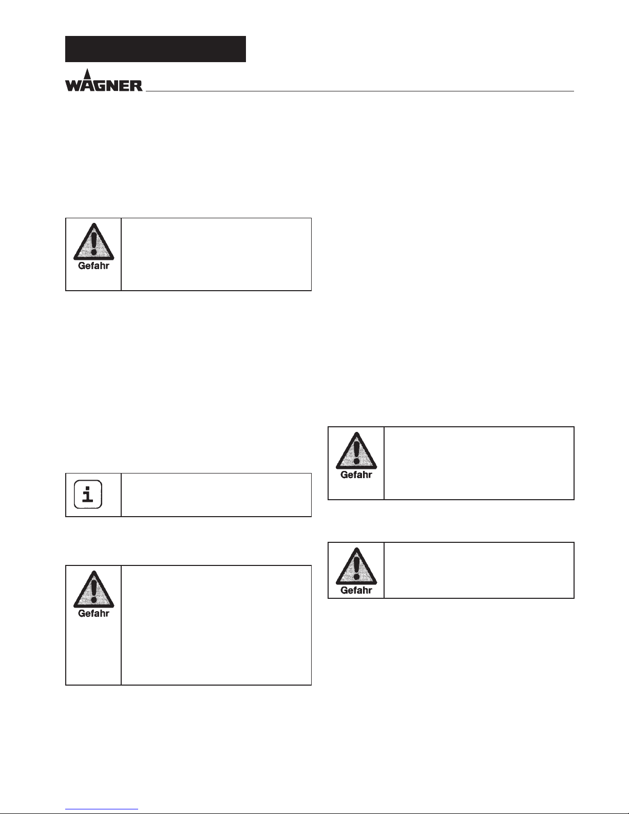
1.20 AUFSTELLUNG IN UNEBENEM GELÄNDE
Die Vorderseite muss nach unten zeigen, um ein Wegrutschen
zu vermeiden.
2 ANWENDUNGSÜBERSICHT
2.1 EINSATZGEBIETE
SF 23 Pro ist ein elektrisch betriebenes Gerät zur luftlosen (Airless) Zerstäubung verschiedener Beschichtungsstoe. Es eignet sich auch für den Betrieb des innengespeisten Farbrollers,
der im Zubehörprogramm verfügbar ist.
Die SF 23 Pro kann sowohl in Werkstätten, als auch auf Baustellen eingesetzt werden.
Die Geräteleistung der SF 23 Pro ist so konzipiert, dass die
Verarbeitung von Dispersionen im Innenbereich für kleine bis
mittlere Objekte möglich ist.
Im Lackierbereich eignen sich das Gerät für alle üblichen Arbeiten wie z.B.:
Türen, Türzargen, Geländer, Möbel, Holzverkleidungen, Zäune, Heizkörper und Stahlteile.
Für Lackierarbeiten empehlt sich die Verwendung eines
Oberbehälters.
2.2 BESCHICHTUNGSSTOFF
Verarbeitbare Beschichtungsstoe
Dispersionen, Latexfarben, wasserverdünnbare und lösemittelhaltige Lacke und Lackfarben, Zweikomponenten Beschichtungsstoe, Dispersionen, Latexfarben.
Die Verarbeitung anderer Beschichtungsstoe sollte nur nach
Rückfrage bei der Firma Wagner erfolgen, da die Haltbarkeit
und auch die Sicherheit des Gerätes dadurch beeinträchtigt
werden können.
Achten Sie auf Airless - Qualität bei den zu
verarbeitenden Beschichtungsstoen.
Das Gerät ist in der Lage Beschichtungsstoe mit einer Viskosi
tät bis zu 20.000 mPas zu verarbeiten. Lässt die Spritzlei-
stung
bei hochviskosen Beschichtungsstoen zu stark nach,
so ist nach Herstellerangabe zu verdünnen.
Beschichtungssto vor Arbeitsbeginn gut umrühren.
Achtung! Beim Aufrühren der Beschichtungsstoe, insbesondere mit motorgetriebenen
Rührwerken, darauf achten, dass keine Luftblasen eingerührt werden.
Luftblasen stören beim Spritzen, können sogar zur Betriebsunterbrechung führen.
2.2.1 BESCHICHTUNGSSTOFFE MIT
SCHARFKANTIGEN ZUSATZSTOFFEN
Diese Partikel üben auf Ventile und Düse, aber auch auf die
Spritzpistole eine stark verschleißende Wirkung aus. Die Lebensdauer dieser Verschleißteile wird dadurch erheblich beeinträchtigt.
Auf schrägen Untergründen ist das Gerät nicht zu
betreiben, da es durch Vibrationen zum Wandern neigt.
D
ANWENDUNGSÜBERSICHT
Page 7
7
Super Finish 23 Pro
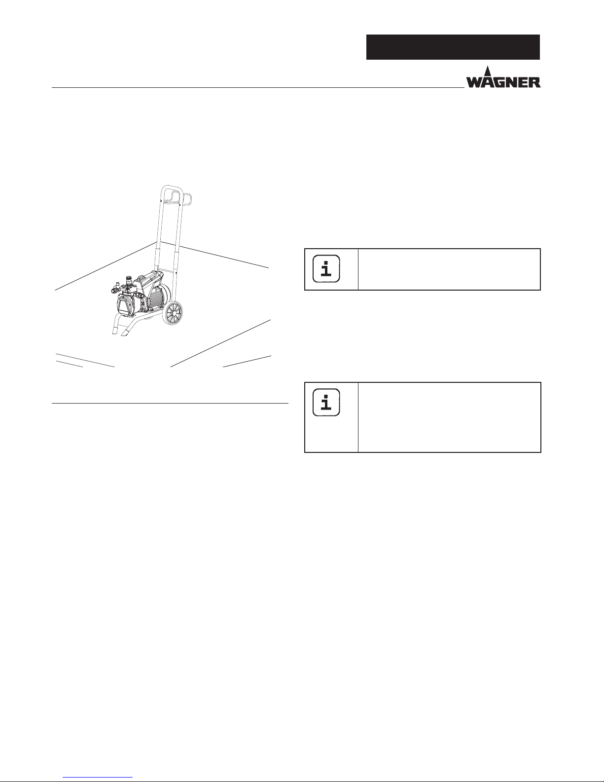
2.2.2 FILTERUNG
Für einen störungsfreien Betrieb ist eine ausreichende Filterung erforderlich. Dazu ist das Gerät mit einem Ansauglter
(Pos. 1), und einem Einstecklter in der Spritzpistole (Pos. 2)
aufgestattet. Eine regelmäßige Kontrolle dieser Filter auf Beschädigung oder Verschmutzung ist dringend zu empfehlen.
Ein im Zubehör erhältlicher Hochdrucklter (Pos. 3) vergrößert die Filteräche und macht das Arbeiten mit dem Gerät
leichter.
GERÄTEBESCHREIBUNG
3 GERÄTEBESCHREIBUNG
3.1 AIRLESS VERFAHREN
Hauptanwendungsgebiete sind dickere Schichten von höherviskosem Beschichtungssto.
Bei der SF 23 Pro saugt eine Membranpumpe den Beschichtungssto an und fördert ihn über den Hochdruckschlauch
zur Spritzpistole mit der Airlessdüse. Hier zerstäubt der Beschichtungssto, da er bis zu einem Druck von max. 25 MPa
(250 bar ) durch den Düsenkern gepresst wird. Dieser hohe
Druck bewirkt eine mikrofeine Zerstäubung des Beschichtungsstoes.
Die Bezeichnung AIRLESS-Verfahren (luftlos) begründet sich
auf den Verzicht von Luft bei der Zerstäubung.
Diese Art zu spritzen hat den Vorteil bei feinster Zerstäubung
und trotzdem nebelarmer Betriebsweise (abhängig von der
korrekten Geräteeinstellung) eine glatte, blasenfreie Oberäche zu erzielen. Neben diesen Aspekten sind auch die hohe
Arbeitsgeschwindigkeit und die große Handlichkeit zu nennen.
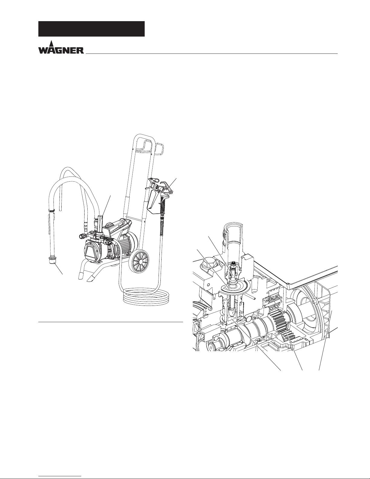
3.2 FUNKTION DES GERÄTES
Zum besseren Verständnis der Funktion kurz der technischen
Aufbau:
SF 23 Pro ist ein elektrisch betriebenes Hochdruck-Farbspritzgerät. Der Elektromotor (1) treibt über ein Planetengetriebe
(2) die Hydraulikpumpe an. Ein Kolben (3) wird auf und ab bewegt und so Hydrauliköl unter die Membran (4) gefördert, die
sich daraufhin bewegt.
Im Detail: Durch die Abwärtsbewegung der Membran önet
das Teller-Einlassventil (5) selbsttäti
g und Beschichtungssto
wird angesaugt. Bei der Aufwärtsbewegung der Membran
wird der Beschichtungssto verdrängt und das Kugel-Auslassventil önet dabei, während das Einlassventil geschlossen ist.
Der Beschichtungssto strömt unter hohem Druck durch den
Hochdruckschlauch zur Spritzpistole und wird beim Austritt
an der Düse zerstäubt.
Das Druckregelventil begrenzt den eingestellten Druck im Hydraulikölkreis und somit auch den Druck des Beschichtungsstoes. Eine Druckveränderung bei Verwendung der gleichen
Düse führt auch zur Veränderung der zerstäubten Farbmenge.
13
5
4
2
1
2
3
D
Page 8
8
Super Finish 23 Pro
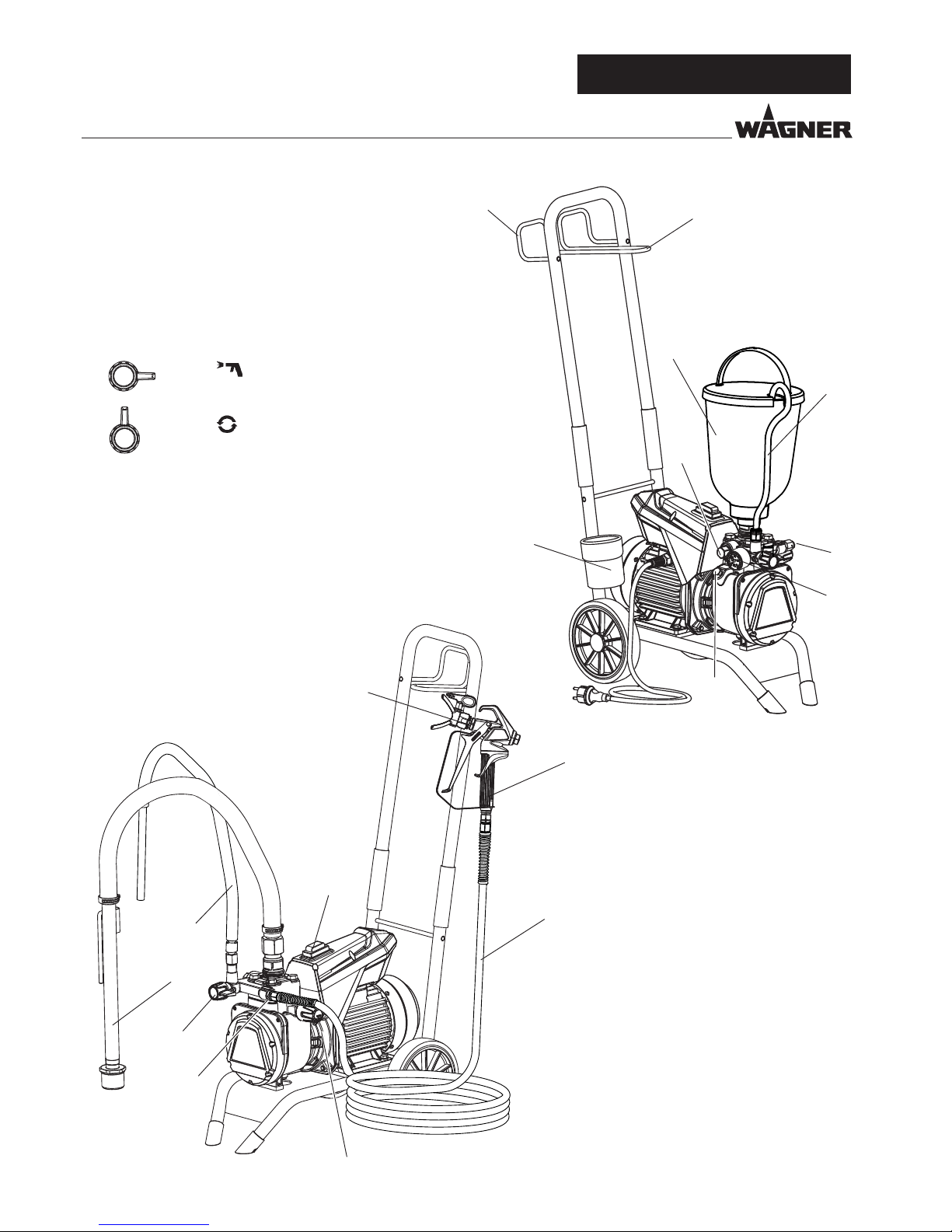
3.3 ERKLÄRUNGSBILDER
1 Düsenhalter mit Düse*
2 Spritzpistole*
3 Hochdruckschlauch*
4 Anschluss für Hochdruckschlauch*
5 Manometer*
6 Druckregelventil
7 EIN / AUS Schalter
8 Druckentlastungsventil
=
Spritzen
=
Zirkulation
9 Rücklaufschlauch*
10 Ansaugsystem*
11 Oberbehälter*
12 Auslassventil
13 Ölmessstab
14 Reinigungsbehälter
15 Schlauchhalter
16 Pistolenhalter
17 Werkzeugtasche (ohne Abbildung)
*Zubehör. Der tatsächliche Lieferumfang ist
abhängig von der Spray Pack Konguration.
6
1
2
3
7
9
10
8
4
5
12
9
14
11
4
15
16
13
D
GERÄTEBESCHREIBUNG
Page 9
9
Super Finish 23 Pro
GERÄTEBESCHREIBUNG
3.5 TECHNISCHE DATEN
Spannung : 230 - 240 Volt ~, 50 Hz
Absicherung : 16 A träge
Geräteanschlussleitung : 6 m lang, 3x1,5 mm²
Max. Stromaufnahme: 7,0 A
Schutzart: IP 54
Aufnahmeleistung Gerät: 1,3 kW
Max. Betriebsdruck : 25 MPa (250 bar)
Max. Volumenstrom : 2,6 l/min
Volumenstrom bei 12 MPa
(120 bar) mit Wasser : 2,3 l/min
Max. zul. Temperatur des
Beschichtungsstos : 43 °C
Max. Viskosität : 20.000 mPas
Leergewicht 27 kg
Hydrauliköl-Füllmenge :
Hydraulikgehäuse
Getriebe (Fett)
1,3 Liter
45 g
Max. Vibration an der
Spritzpistole : kleiner 2,5 m/s²
Max. Schalldruckpegel : 75 dB (A)*
*Messort: Abstand 1m seitlich vom Gerät und 1,60m über
dem Boden, 12 MPa (120bar) Betriebsdruck, schallharter
Boden
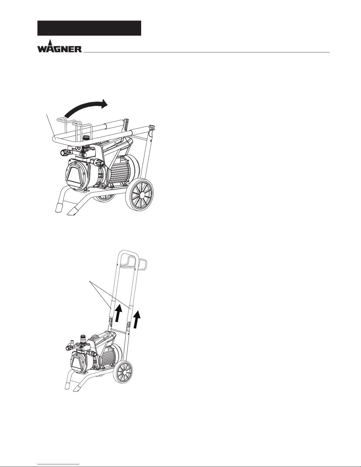
3.4 EINSTELLUNG DER DEICHSEL
Klappen Sie die Deichsel (1) nach oben (die Hülsen fallen nach
unten und xieren die Deichsel in der Endposition).
Transport im Fahrzeug
Gerät im Fahrzeug mit geeignetem Befestigungsmittel sichern.
Das Gerät kann bei Bedarf auf die Seite gelegt werden. Hier
bitte darauf achten, dass keine Anbauteile beschädigt werden
können. Achtung: Farb- oder Lösemittelreste können aus den
Anschlussverschraubungen austreten!
Schieben Sie die Hülsen (2) nach oben, um die Deichsel bei
Bedarf wieder einzuklappen.
2
1
D
Page 10

10
Super Finish 23 Pro
4 INBETRIEBNAHME
4.1 GERÄT MIT ANSAUGSYSTEM
1. Auf saubere Dichtächen an den Anschlüssen achten.
Darauf achten, dass der rote Einlauf (1) in den Beschichtungssto-Eingang (4) eingesetzt ist.
2. Überwurfmutter (2) am Ansaugschlauch (3) auf den Beschichtungssto-Eingang (4) mit beiliegendem Schlüssel
(41mm) schrauben und handfest anziehen.
3. Überwurfmutter (5) am Rücklaufschlauch (6) auf den Anschluss (7) schrauben (Schlüsselweite 22mm).
4.3 HOCHDRUCKSCHLAUCH UND SPRITZPISTOLE
1. Hochdrucksc
hlauch (9) am Schlauchanschluss anschrau-
ben.
2. Spritzpistole (10) am Hochdruckschlauch anschrauben.
3. Alle Überwurfmuttern am Hochdruckschlauch fest anziehen, damit kein Beschichtungssto austritt.
4. Den Düsenhalter mit der ausgewä
hlten Düse auf die
Spritzpistole schrauben, ausrichten und fest anziehen. (siehe auch Anleitung der Spritzpistole / Düsenhalter)
Beim Abschrauben des Hochdruckschlauches
am Schlauchanschluss mit Schlüssel 22mm
gegenhalten.
4.4 ANSCHLUSS AN DAS STROMNETZ
Der Anschluss muss immer über eine vorschriftsmäßig geerdete Schutzkontaktsteckdose mit Fehlerstrom-Absicherung (FI-Sicherung) erfolgen.
Vor Anschluss an das Stromnetz darauf achten, dass die Netzspannung übereinstimmt mit der Angabe auf dem Leistungsschild am Gerät.
4.2 GERÄT MIT OBERBEHÄLTER
1.
Auf saubere Dichtächen an den Anschlüssen achten.
Darauf achten, dass der rote Einlauf (1) in den Beschichtungssto-Eingang (4) eingesetzt ist.
2. Überwurfmutter (5) am Rücklaufschlauch (6) auf den Anschluss (7) schrauben .
3. Oberbehälter (8) auf Beschichtungssto-Eingang (4)
schrauben und handfest anziehen.
Drücken Sie vor der Inbetriebnahme von
oben auf das Einlassventil im Beschichtungsstoeingang (4). Dadurch wird sichergestellt,
dass das Ventil nicht blockiert/verklebt ist.
1
4
2
3
5
6
7
1
4
5
6
7
8
9
9
10
10
D
INBETRIEBNAHME
Page 11
11
Super Finish 23 Pro
4.5 BEI ERSTINBETRIEBNAHME
REINIGUNG VON KONSERVIERUNGSMITTEL
Gerät mit Ansaugsystem
1. Ansaugsystem in einen mit geeignetem Reinigungsmittel
gefüllten Behälter eintauchen. (Empfehlung: Wasser)
Gerät mit Oberbehälter
2. Geeignetes Reinigungsmittel in den Oberbehälter einfüllen. (Empfehlung: Wasser)
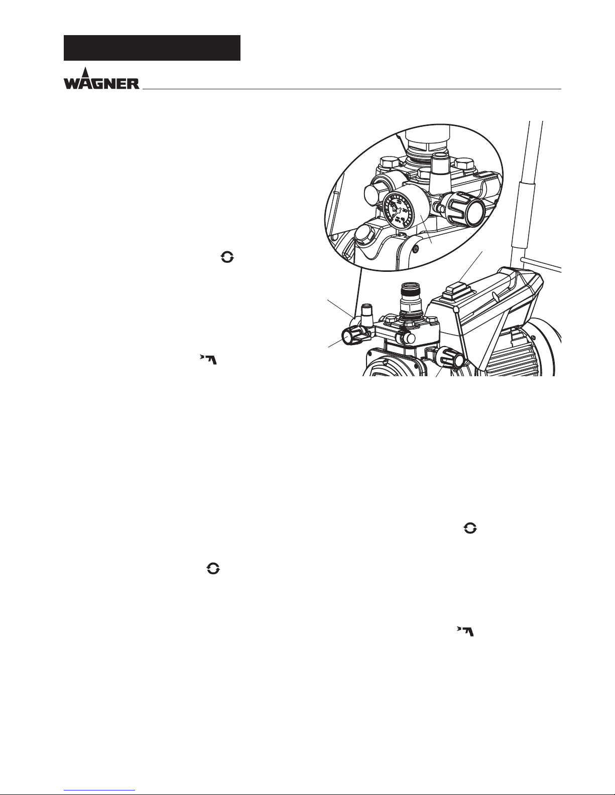
3.
Druckentlastungsventil (Pos. 1) auf (Zirkulation) stel-
len, das Gerät läuft an.
4. Gerät mit EIN /AUS Schalter (2) einschalten (Pos. I).
5. Druckregulierknopf (3) bis zum Anschlag nach rechts dre-
hen.
6. Abwarten bis am Rücklaufschlauch Reinigungsmittel austritt.
7. Druckregulierknopf
(3) ca. eine Umdrehung zurückdre-
hen.
8. Druckentlastungsventil (1) auf
(Spritzen) stellen.
Druck wird im Hochdruckschlauch aufgebaut (sichtbar
am Manometer (4)).
9. Düse der Spritzpistole in einen oenen Sammelbehälter
richten und Abzugsbügel der Spritzpistole ziehen.
10. Durch Drehen des Druckregulierknopfes (3) nach rechts,
wird der Druck erhöht. Stellen Sie ca. 10 MPa (100 bar) am
Ma
nometer ein.
11. Reinigungsmittel aus dem Gerät für ca. 1-2 min (~5 Liter)
in den oenen Sammelbehälter spritzen.
4.7 GERÄT MIT BESCHICHTUNGSSTOFF IN BETRIEB
NEHMEN
Gerät mit Ansaugsystem
1. Ansaugsystem in mit Beschichtungssto gefüllten Behälter eintauchen.
Gerät mit Oberbehälter
2. Beschichtungssto in den Oberbehälter einfüllen.
3.
Druckentlastungsventil (1) auf (Zirkulation) stellen,
das Gerät läuft an.
4. Gerät mit EIN /AUS Schalter (2) einschalten (Pos. I).
5. Druckregulierknopf (3) bis zum Anschlag nach rechts drehen. Wenn das Geräusch der Ventile sich verändert, so ist
das Gerät entlüftet und saugt Beschichtungssto an.
6. Tritt Beschichtungssto aus dem Rücklaufschlauch aus,
Druckregulierknopf (3) ca. eine Umdrehung zurückdrehen.
7. Druckentlastungsventil (1) auf
(Spritzen) stellen.
Druck wird im Hochdruckschlauch aufgebaut (sichtbar
am Manometer (4)).
8. Spritzpistole abziehen und in einen oenen Sammelbehälter spritzen, um restliches Reinigungsmittel aus dem
Gerät zu entfernen. Wenn Beschichtungssto aus der
Düse austritt Spritzpistole schließen.
9. Den Spritzdruck durch Drehen des Druckregulierknopfes
(3) einstellen.
10. Das Gerät ist spritzbereit.
4.6 GERÄT HYDRAULIKSYSTEM ENTFÜFTEN,
WENN DAS GERÄUSCH DES EINLASSVENTILS
NICHT ZU HÖREN IST
1. Gerät mit EIN /AUS Schalter (2) einschalten (Pos. I).
2. Druckregulierknopf (3) drei Umdrehungen nach links
drehen.
3. Druckentlastungsventil (1) auf
(Zirkulation) stellen.
Das Hydrauliksystem entlüftet sich. Gerät zwei bis drei Minuten eingeschaltet lassen.
4. Druckregulierknopf (3) bis zum Anschlag nach rechts dre-
hen.
5. Wenn nicht, Punkt 2 bis 4 wiederholen.
1
2
4
3
4
D
INBETRIEBNAHME
Page 12
12
Super Finish 23 Pro
5 SPRITZTECHNIK
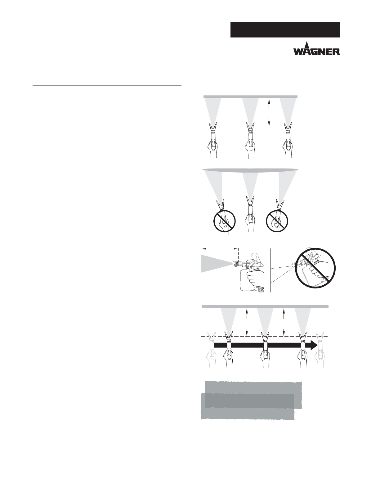
•
Der Schlüssel für ein hochwertiges Ergebnis ist die
gleichmäßige Beschichtung der gesamten Fläche.
Bewegen Sie Ihren Arm mit konstanter Geschwindigkeit und
halten Sie die Spritzpistole in einem konstanten Abstand
über der Oberäche. Optimal ist ein Abstand von ca. 30 cm
zwischen Spritzdüse und Oberäche. (Abb. A)
•
Halten Sie die Spritzpistole parallel zur Oberäche. Führen
Sie die Bewegung mit dem gesamten Arm und nicht aus dem
Handgelenk aus. (Abb. B)
•
Halten Sie die Spritzpistole im rechten Winkel zur Oberäche.
Anderenfalls wird die Beschichtung an einem Ende dicker als
am anderen. (Abb. C)
•
Ziehen Sie den Abzugsbügel nachdem Sie die Bewegung
begonnen haben. Lassen Sie den Abzugsbügel los, bevor Sie
die Bewegung beenden. (Abb. D) Unterbrechungen innerhalb
der Sprühäche vermeiden.
•
Lassen Sie jede Bahn um ca. 30 % überlappen. Dadurch
entsteht eine gleichmäßige Beschichtung. (Abb. E)
•
Verwenden Sie die kleinstmögliche Druckeinstellung, mit der
das gewünschte Spritzbild erzeugt werden kann, um Sprühnebel
zu minimieren.
•
Um bei Lackierarbeiten besonders gute Oberächen zu
erzielen, gibt es spezielle Zubehöre im Wagner Programm,
z.B. die FineFinish Düsen. Ihr Wagner Händler berät Sie gern.
SPRITZTECHNIK / HANDHABUNG DES HOCHDRUCKSCHLAUCHS / ARBEITSUNTERBRECHNUNG
30 cm
A)
B)
C)
30 cm
30 cm30 cm
D)
30% Überlappen
E)
D
Page 13
13
Super Finish 23 Pro
6 HANDHABUNG DES
HOCHDRUCKSCHLAUCHES
Das Gerät ist mit einem speziell für Membranpumpen geeigneten Hochdruckschlauch ausgerüstet.
Verletzungsgefahr durch undichten Hochdruckschlauch. Beschädigten Hochdruckschlauch sofort ersetzen.
Niemals defekten Hochdruckschlauch selbst
reparieren!
Der Hochdruckschlauch ist sorgsam zu behandeln. Scharfes
Biegen oder Knicken vermeiden, kleinster Biegeradius etwa
20 cm.
Hochdruckschlauch nicht überfahren, sowie vor scharfen
Gegenständen und Kanten schützen.
Niemals am Hochdruckschlauch ziehen, um das Gerät zu bewegen.
Darauf achten, dass der Hochdruckschlauch sich nicht verdreht. Durch Verwendung einer Wagner Spritzpistole mit
Drehgelenk und einer Schlauchtrommel kann dies verhindert
werden.
Für die Handhabung des Hochdruckschlauches bei der Arbeit am Gerüst hat
sich als am Vorteilhaftesten erwiesen, den
Schlauch stets an der Außenseite des Gerüstes zu führen.
Bei alten Hochdruckschläuchen steigt das
Risiko von Beschädigungen.
Wagner empehlt den Hochdruckschlauch
nach 6 Jahren auszutauschen.
Aus Gründen der Funktion, Sicherheit und
Lebensdauer nur WAGNER Original-Hochdruckschläuche verwenden.
7 ARBEITSUNTERBRECHUNG
1. Druckentlastungsventil auf (Druckentlastung, Zirkula-
tion) stellen.
2. Gerät mit EIN /AUS Schalter ausschalten (Pos. 0).
3. Abzugsbügel der Spritzpistole ziehen, um Hochdruckschlauch und Spritzpistole vom Druck zu entlasten.
4. Spritzpistole sichern, siehe Betriebsanleitung der Spritzpistole.
5. Düse aus dem Düsenhalter nehmen und in einem kleinen
Gefäß mit geeignetem Reinigungsmittel lagern.
6. Ansaugsystem im Beschichtungssto eingetaucht lassen
oder dieses in das entsprechende Reinigungsmittel eintauchen. Ansauglter und Gerät sollen nicht austrocknen.
7. Materialbehälter abdecken, um ein Austrocknen der Farbe zu verhindern.
Beim Einsatz von schnelltrocknenden oder
Zweikomponenten-Beschichtungsstoen,
Gerät unbedingt innerhalb der Verarbeitungszeit mit geeignetem Reinigungsmittel
durchspülen, da das Gerät ansonsten nur mit
erheblichen Aufwand gereinigt werden kann.
HANDHABUNG DES HOCHDRUCKSCHLAUCHS / ARBEITSUNTERBRECHNUNG
D
Page 14

14
Super Finish 23 Pro
Vorsicht! Nicht in Behälter mit kleiner Önung (Spundloch) pumpen oder spritzen!
Siehe Sicherheitsvorschriften.
8. Druckentlastungsventil auf ( Zirkulation) stellen.
9. Geeignetes Reinigungsmittel einige Minuten im Kreislauf
pumpen.
Die Reinigungswirkung erhöht sich, wenn
die Spritzpistole im Wechsel geönet und
geschlossen wird.
10. Druckentlastungsventil auf (Spritzen) stellen.
11. Restliches Reinigungsmittel in einen oenen Behälter
pumpen, bis das Gerät leer ist.
12. Druckentlastungsventil auf
(Zirkulation) stellen.
13. Gerät mit EIN /AUS Schalter ausschalten (Pos. 0)
• Gerät mit Oberbehälter
1.
Druckentlastungsventil auf (Zirkulation) stellen.
2. Gerät mit EIN /AUS Schalter einschalten (Pos. I).
3. Druckregelventil zurückdrehen um einen minimalen
Spritzdruck einzustellen.
4.
Druckentlastungsventil auf (Spritzen) stellen.
5. Abzugsbügel an der Spritzpistole ziehen, um restlichen
Beschichtungssto aus Oberbehälter, Hochdruckschlauch
und Spritzpistole in einen oenen Behälter zu pumpen
(eventuell Druck am Druckregelventil langsam erhöhen
um eine höhere Materialförderung zu erhalten).
Bei lösemittelhaltigen Beschichtungsstoen
muss der Behälter geerdet werden.
Vorsicht! Nicht in Behälter mit kleiner Önung (Spundloch) pumpen oder spritzen!
Siehe Sicherheitsvorschriften.
6. In den Oberbehälter geeignetes Reinigungsmittel einfüllen.
7.
Druckentlastungsventil auf (Zirkulation) stellen.
8. Geeignetes Reinigungsmittel einige Minuten im Kreislauf
pumpen.
9.
Druckentlastungsventil auf (Spritzen) stellen.
10. Restliches Reinigungsmittel in einen oenen Behälter
pumpen, bis das Gerät leer ist.
11.
Druckentlastungsventil auf (Zirkulation) stellen.
12. Gerät mit EIN /AUS Schalter ausschalten (Pos. 0).
8 GERÄTEREINIGUNG
Sauberkeit ist die sicherste Gewährleistung für einen störungsfreien Betrieb. Nach Beendigung der Spritzarbeiten Gerät reinigen. Auf keinen Fall dürfen Beschichtungsstoreste im
Gerät antrocknen und sich festsetzen. Das zur Reinigung verwendete Reinigungsmittel (nur mit einem Flammpunkt über
21 °C) muss dem Beschichtungssto entsprechen.
Bei wasserverdünnbaren Beschichtungsstoen verbessert warmes Wasser die Reinigung.
• Spritzpistole sichern, siehe Betriebsanleitung der Spritz-
pistole.
Düse und Düsenhalter demontieren und reinigen
•
Gerät mit Ansaugsystem
1. Druckentlastungsventil auf
(Zirkulation) stellen.
2. Gerät mit EIN /AUS Schalter einschalten (Pos. I).
3. Ansaugsystem aus dem Materialbehälter nehmen. Der
Rücklaufschlauch verbleibt über dem Materialbehälter,
bis kaum noch Beschichtungssto austritt.
4. Ansaugsystem in ein geeignetes Reinigungsmittel eintauchen.
5. Druckregelventil zurückdrehen um einen minimalen
Spritzdruck einzustellen.
6. Druckentlastungsventil auf
(Spritzen) stellen.
7. Abzugsbügel an der Spritzpistole ziehen, um restlichen
Beschichtungssto aus dem Hochdruckschlauch und der
Spritzpistole in einen oenen Behälter zu pumpen (eventuell Druck am Druckregelventil langsam erhöhen um
eine höhere Materialförderung zu erhalten).
Bei lösemittelhaltigen Beschichtungsstoen
muss der Behälter geerdet werden.
D
GERÄTEREINIGUNG
Page 15
15
Super Finish 23 Pro
8.1 GERÄTEREINIGUNG VON AUSSEN
Zuerst Netzstecker aus der Steckdose ziehen.
Kurzschlussgefahr durch eindringendes Wasser!
Gerät niemals mit Hochdruck- oder Dampfhochdruckreiniger abspritzen.
Hochdruckschlauch nicht in Lösemittel einlegen. Außenseite nur mit einem getränkten
Tuch abwischen.
Gerät außen mit einem in geeigneten Reinigungsmittel getränktem Tuch abwischen.
8.2 ANSAUGFILTER
Saubere Filter gewährleisten stets maximale
Fördermenge, konstanten Spritzdruck und
einwandfreies Funktionieren des Gerätes.
Gerät mit Ansaugsystem
1. Filter (Pos. 1) vom Ansaugrohr abschrauben.
2. Filter reinigen oder austauschen.
Reinigung mit einem harten Pinsel und entsprechendem
Reinigungsmittel durchführen.
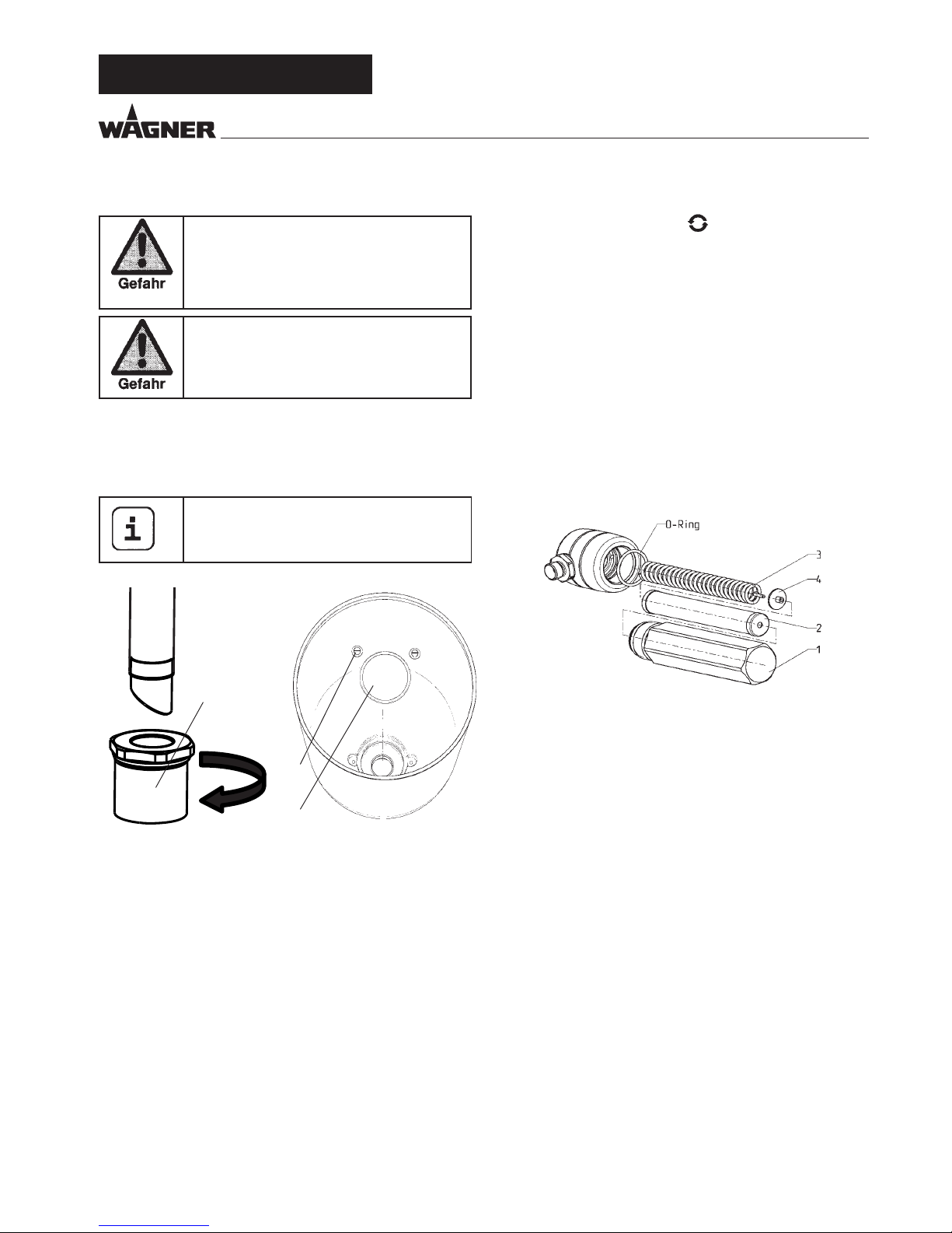
8.3 HOCHDRUCKFILTER ZUBEHÖR
1. Druckentlastungsventil auf (Druckentlastung, Zirkulation) stellen.
2. Gerät mit EIN /AUS Schalter ausschalten (Pos. 0)
3. Hochdrucklter önen und Filtereinlage reinigen, dazu:
4. Filtergehäuse (1) von Hand abschrauben.
5. Filtereinsatz (2) herausnehmen und Stützfeder (3) herausziehen.
6. Alle Teile mit entsprechendem Reinigungsmittel reinigen.
Falls Druckluft vorhanden – Filtereinsatz und Stützfeder
durchblasen.
7. Bei der Montage des Filters auf den korrekten Sitz der
Stützscheibe (4) im Filtereinsatz achten und den O-Ring
am Filtergehäuse auf Beschädigungen kontrollieren.
8. Filtergehäuse bis auf Anschlag von Hand aufschrauben
(eine hohe Anzugskraft erschwert nur eine spätere Demontage).
GERÄTEREINIGUNG
Gerät mit Oberbehälter
1. Mit Schraubendreher Schrauben (2) lösen
2. Filterscheibe (1) mit einem Schraubendreher anheben
und herausnehmen
3. Filterscheibe reinigen oder austauschen
Reinigung mit einem harten Pinsel und entsprechendem
Reinigungsmittel durchführen.
1
2
Ansaugsystem Oberbehälter
1
D
Page 16
16
Super Finish 23 Pro
9 WARTUNG
9.1 ALLGEMEINE WARTUNG
Aus Sicherheitsgründen ist eine jährliche Inspektion durch Fachleute dringend empfohlen. Beachten Sie hierzu auch alle gültigen
nationalen Vorschriften. In Deutschland ist
diese Überprüfung (inkl. Nachweis) von der
Berufsgenossenschaft zwingend vorgeschrieben.
Mindestprüfungen vor jeder Inbetriebnahme
1. Hochdruckschlauch, Spritzpistole mit Drehgelenk und
Geräteanschlussleitung mit Stecker auf Beschädigung
prüfen.
2. Ablesbarkeit des Manometers prüfen.
Prüfungen in regelmäßigen Abständen
1. Einlass- und Auslassventil auf Verschleiß prüfen, reinigen
und Verschleißteile auswechseln.
2. Filtereinsätze (Spritzpistole, Ansaugsystem) reinigen gegebenenfalls ersetzen.
9.2 HOCHDRUCKSCHLAUCH
Hochdruckschlauch optisch auf eventuell vorhandene Einschnitte oder Ausbeulungen, insbesondere am Übergang in
die Armatur, prüfen. Überwurfmuttern müssen sich frei drehen lassen. Die Leitfähigkeit von kleiner 1 Mega Ohm muss
über der gesamten Länge vorhanden sein.
Alle elektrischen Prüfungen vom WagnerService durchführen lassen.
Bei alten Hochdruckschläuchen steigt das
Risiko von Beschädigungen.
Wagner empehlt den Hochdruckschlauch
nach 6 Jahren auszutauschen.
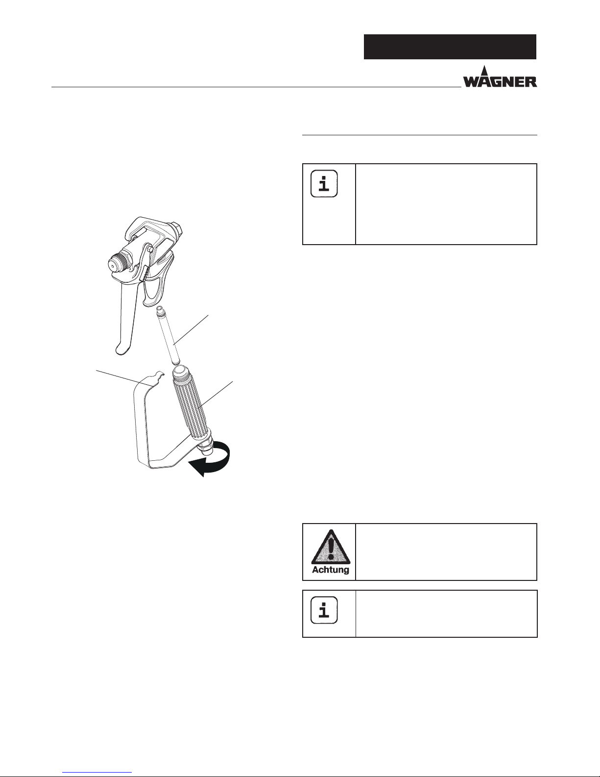
8.4 REINIGUNG DER AIRLESSSPRITZPISTOLE
1. Airless-Spritzpistole bei niedrigem Betriebsdruck mit geeignetem Reinigungsmittel durchspülen.
2. Düse gründlich mit geeignetem Reinigungsmittel reinigen, so dass keine Beschichtungsstoreste zurückbleiben.
3. Airless-Sprizpistole außen gründlich reinigen.
1.
Lösen Sie die obere Seite des Abzugsschutzes (1) vom Pistolenkopf
2. Verwenden Sie die Unterseite des Abzugsschutzes als
Schraubenschlüssel, und lösen Sie mit diesem den Handgri (2) und entfernen diesen vom Pistolenkopf.
3. Den alten Filter (3) aus dem Spritzpistolenkopf ziehen.
Reinigen oder tauschen Sie diesen aus.
4. Den neuen Filter mit dem konischen Ende zuerst in den
Spritzpistolenkopf einschieben.
5. Den Gri so weit in den Spritzpistolenkopf einschieben,
bis er fest sitzt. Ziehen Sie diesen mit dem Abzug- Schraubenschlüssel fest.
6. Lassen Sie den Abzugsschutz wieder in den Pistolenkopf
einrasten.
Einstecklter in der Airless-Spritzpistole
1
3
2
D
GERÄTEREINIGUNG / WARTUNG
Page 17
17
Super Finish 23 Pro
10 REPARATUREN AM GERÄT
Gerät ausschalten.
Vor allen Reparaturen – Netzstecker aus der
Steckdose ziehen.
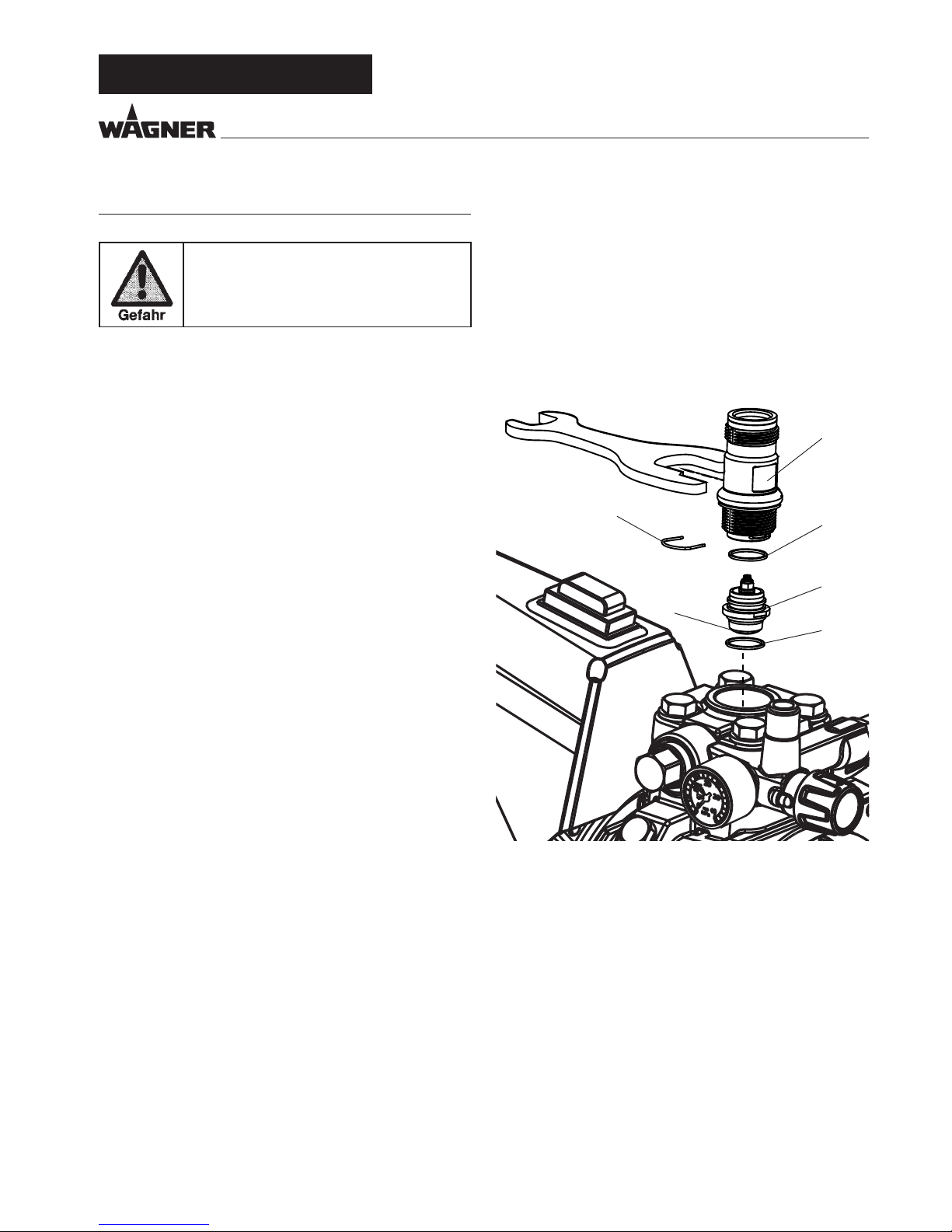
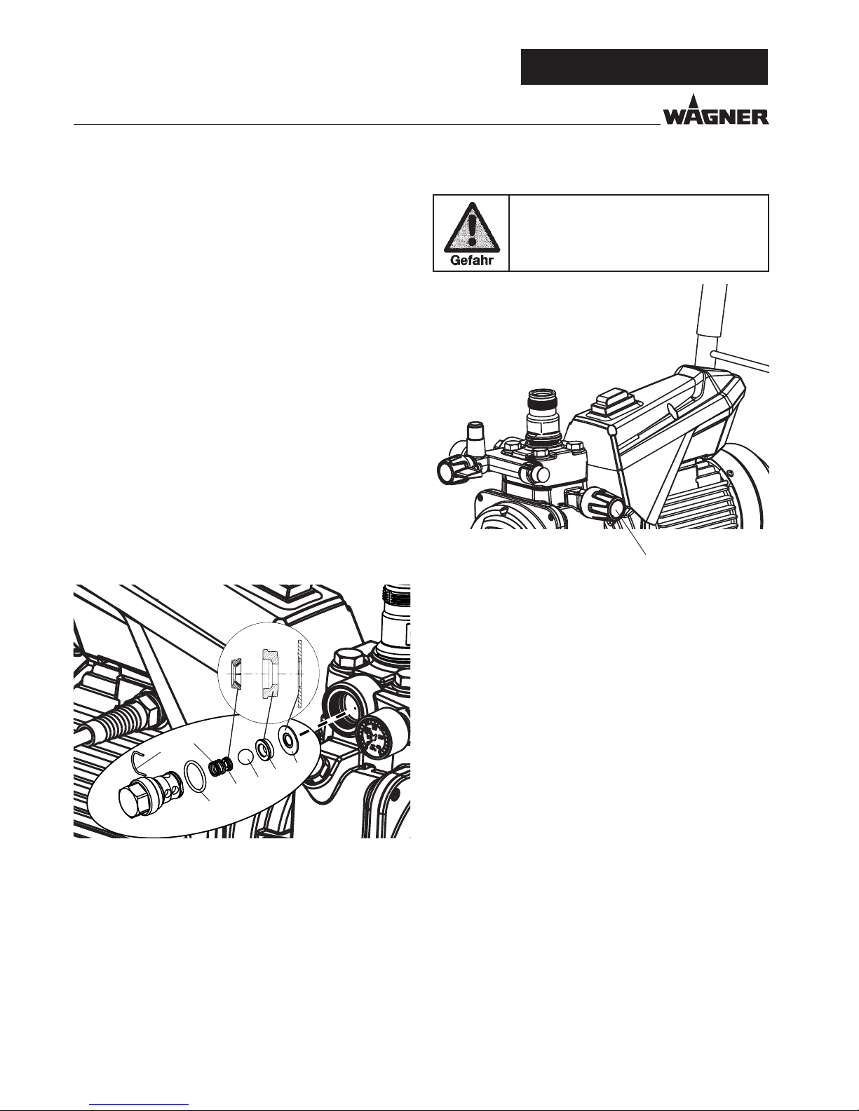
10.1 EINLASSVENTIL
1. Beiliegenden Schlüssel (30mm) am Gehäuse (1) ansetzen.
2. Mit leichten Hammerschlägen auf das Schlüsselende das
Gehäuse (1) lösen.
3. Gehäuse mit Einlassventil (2) aus der Farbstufe herausschrauben.
4. Spange (3) mit beiliegendem Schraubendreher abziehen.
5. Beiliegenden Schlüssel (30mm) am Einlassventil (2) ansetzen. Unter Drehen Einlassventil vorsichtig herausziehen.
6. Ventilsitz (4) mit Reinigungsmittel und Pinsel reinigen (darauf achten, dass keine Pinselhaare zurückbleiben).
7. Dichtungen (5, 6) reinigen und auf Beschädigungen prüfen, eventuell austauschen.
8. Alle Ventilteile auf Beschädigung kontrollieren. Bei sichtbarem Verschleiß Einlassventil austauschen.
REPARATUREN AM GERÄT
Montage
1. Einlassventil (2) in das Gehäuse (1) einsetzen und mit
Spange (3) sichern. Darauf achten, dass die (schwarze)
Dichtung (5) im Gehäuse montiert ist.
2. Einheit aus Gehäuse und Einlassventil in die Farbstufe einschrauben. Die gleiche (schwarze) Dichtung (6) muss in
der Farbstufe montiert sein.
3. Gehäuse mit Schlüssel (30mm) anziehen und mit drei
leichten Hammerschlägen auf das Schlüsselende festziehen (entspricht ca. 90 Nm Anzugsmoment).
1
3
2
5
6
4
D
Page 18
18
Super Finish 23 Pro
10.2 AUSLASSVENTIL
1. Auslassventil mit Schlüssel (22mm) aus der Farbstufe herausschrauben.
2. Vorsichtig Spange (1) mit beiliegendem Schraubendreher
abziehen, Druckfeder (2) drückt Kugel (4) und Ventilsitz (5)
heraus.
3. Einzelteile reinigen oder austauschen.
4. O-Ring (7) auf Beschädigung prüfen.
5. Auf Einbaulage achten bei Montage von Federstützring
(3) (wird in Druckfeder (2) eingeklipst), Auslass-Ventilsitz
(5) und Dichtring (6), -> siehe Abbildung
Bitte beachten Sie auch die folgenden Hinweise:
1. Das Drehmoment für die Montage des Auslassventils ist
50 Nm.
2. Überprüfen Sie im Normalbetrieb regelmäßig, ob sich das
Auslassventil gelöst hat.
3. Ersetzen Sie immer auch die Dichtung (6), wenn Sie das
Auslassventil demontiert haben, unabhängig davon,
welche Komponente Sie austauschen möchten. Hinweis:
Die Dichtung (6) bendet sich innerhalb der Farbstufe.
4. Die Nut in der Dichtung (6) zeigt beim Austausch nach
außen.
10.3 DRUCKREGELVENTIL
Druckregelventil (1) nur vom Kundendienst
austauschen lassen.
Der max. Betriebsdruck ist vom Kundendienst neu einzustellen.
1
7
2
3
4
5
6
1
D
REPARATUREN AM GERÄT
Page 19
19
Super Finish 23 Pro
REPARATUREN AM GERÄT
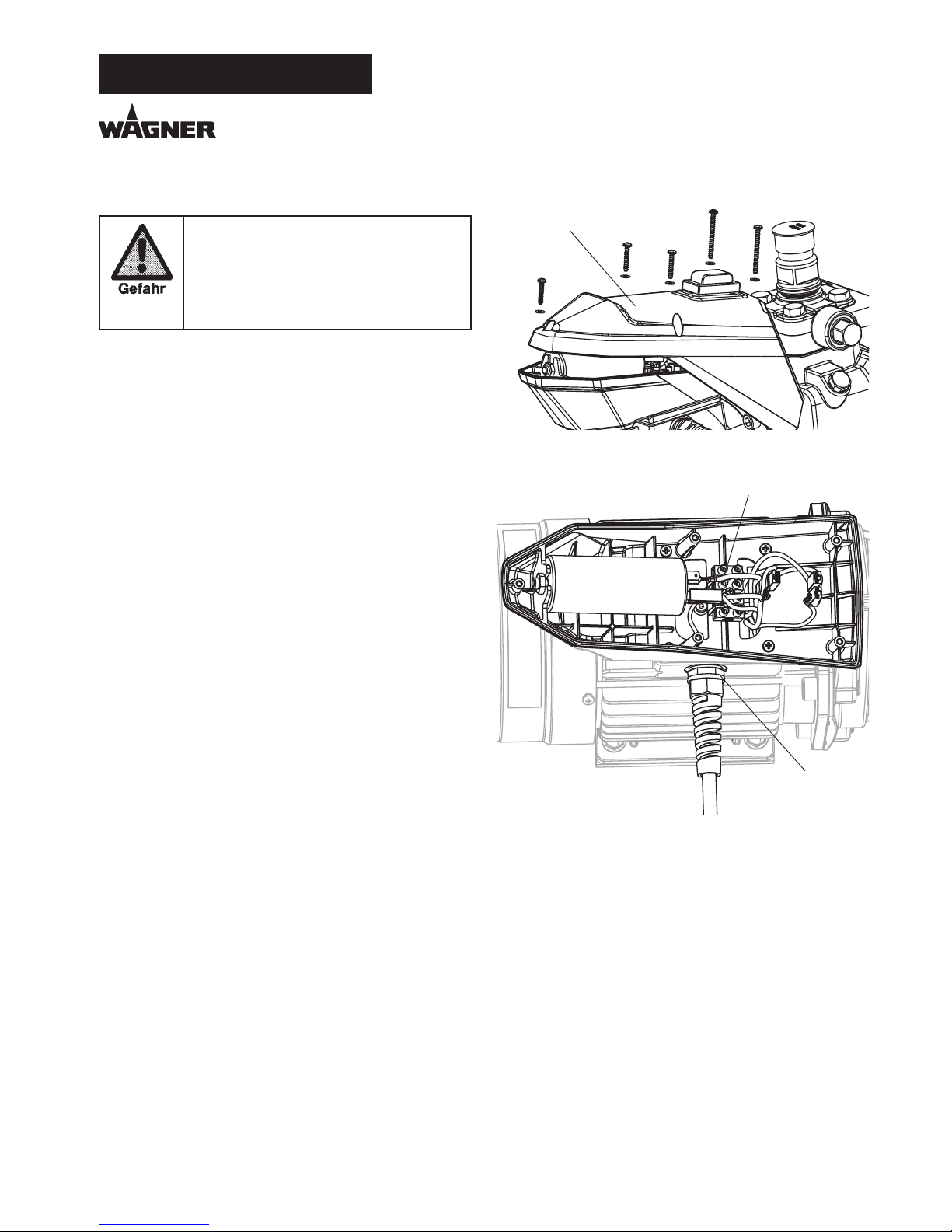
10.4 GERÄTEANSCHLUSSLEITUNG AUSTAUSCHEN
Nur von einer Elektrofachkraft durchführen
lassen. Für unsachgemäße Installation wird
keine Haftung übernommen.
Gerät ausschalten.
Vor allen Reparaturen – Netzstecker aus der
Steckdose ziehen.
1. Hintere Abdeckung (1) durch lösen der Schrauben entfernen.
2. Kabelverschraubung (2) lösen.
3. Litzen in der Netzanschlussklemme (3) lösen.
4. Geräteanschlussleitung austauschen.
(Nur eine zugelassene Netzleitung der Bezeichnung H07-
RNF mit spritzwasserdichtem Stecker darf verwendet werden)
5. Grün/gelbe Litze an Anschluss PE montieren
6. Abdeckungen wieder sorgfältig montieren (Achtung! kein
Kabel einklemmen!).
10.5 TYPISCHE VERSCHLEISSTEILE
Trotz Verwendung hochwertiger Materialien ist durch die stark
abrasive Wirkung der Farben mit Verschleiß an folgenden Teilen zu rechnen:
Einlassventil (Ersatzteil Bestell-Nr: 2393043)
Austausch siehe Punkt 10.1
(Ausfall bemerkbar durch Leistungsverlust und/oder schlechtes bzw. kein Ansaugen - eine gründliche Reinigung kann
auch auch schon zu einer Verbesserung führen)
Auslassventil (Ersatzteil Bestell-Nr: 2393106)
Austausch siehe Punkt 10.2
(Ausfall bemerkbar durch Leistungsverlust und/oder
schlechtes Ansaugen) Das Auslassventil hält erfahrungsgemäß deutlich länger als das Einlassventil. Eventuell ist hier
eine gründliche Reinigung hilfreich.
1
2
3
D
Page 20

20
Super Finish 23 Pro
10.6 SCHALTPLAN
/FU[TUFDLFS
230V / 50Hz
,MFNNMFJTUF
HSàO/HFMC
CMBV
IFMMCMBV
CSBVO
MPUPS
NJU5FNQFSBUVSTDIBMUFS
M
1~
Z2
U2
#FUSJFCTLPOEFOTBUPS
C = 25µF
400V
TDIXBS[
155°C
N
L
Z1
SPU
HSàOHFMC
CMBV
TDIXBS[
N
MPUPSTDIBMUFS 8A
b
U<
P1
P2
6
3
IFMMCMBV
CMBV
TDIXBS[
340380
254518
254519
b
D
REPARATUREN AM GERÄT
Page 21

21
Super Finish 23 Pro
10.7 HILFE BEI STÖRUNGEN
ART DER STÖRUNG WAS NOCH? MÖGLICHE URSACHE MASSNAHMEN ZUR BEHEBUNG DER STÖRUNG
Gerät läuft
nicht an
Keine Spannung vorhanden
Spannungsversorgung prüfen
Gerätesicherung hat angesprochen
Motor abkühlen lassen
Gerät saugt
nicht an
Keine Luftblasen treten am
Rücklaufschlauch aus
Einlass- oder Auslassventil
verklebt / verschlissen
Ventile Demontieren und reinigen (-> siehe
Pkt.10.1/10.2). Verschlissenen Teile ersetzen
Druckregelventil ganz zurückgedreht
Drehen Sie das Druckregelventil bis zum Anschlag nach rechts.
Luftblasen treten aus dem
Rücklaufschlauch aus
Gerät saugt Nebenluft Kontrollieren Sie: Ansaugsystem fest ange-
zogen?
Roter Einlauf im Beschichtungsstoeingang
fehlt(-> siehe Pkt.4.1)
Gerät erzeugt
keinen Druck
Gerät hat angesaugt Luft im Ölkreislauf Ölkreislauf im Gerät entlüften, dazu Druck-
regelventil ganz nach links drehen (bis zum
Überdrehen) und ca. 2-3 min laufen lassen,
danach Druckregelventil nach rechts drehen
und Spritzdruck einstellen (Vorgang evtl.
mehrmals wiederholen).
Gerät ist auf Druck
gekommen, jedoch beim
Spritzen bricht der Druck
auch am Manometer zusammen
Ansauglter verstopft Kontrollieren Sie den Ansauglter / evtl. rei-
nigen / ersetzen
Farbe in diesem Zustand
nicht verarbeitbar, die
Farbe verklebt durch ihre
Eigenschaften die Ventile
(Einlassventil) und die Förderleistung ist zu gering
Farbe verdünnen
Gerät ist auf Druck gekommen, jedoch beim Spritzen
bricht der Spritzstrahl zusammen, Manometer zeigt dennoch hohen Druck an
verstopfte Filter lassen zu
wenig Farbe durch
(Hochdrucklter wenn vorhanden), Pistolenlter kontrollieren / reinigen
Düse verstopft Düse reinigen
Gerät erzeugt nicht den max.
möglichen Druck, am Rücklaufschlauch tritt trotz Spritzstellung Farbe aus
Entlastungsventil defekt
Wenden Sie sich an den Wagner Kundendienst.
D
ERSATZTEILE UND ZUBEHÖR
Page 22
22
Super Finish 23 Pro
ERSATZTEILE UND ZUBEHÖR
11 ERSATZEILE UND ZUBEHÖR
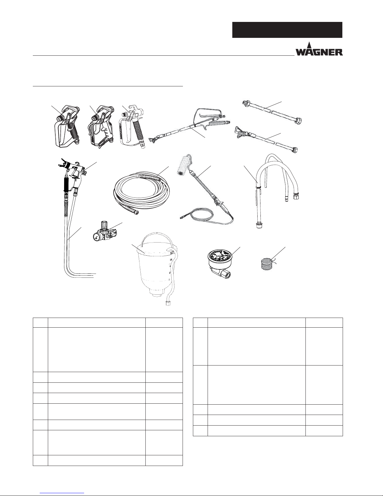
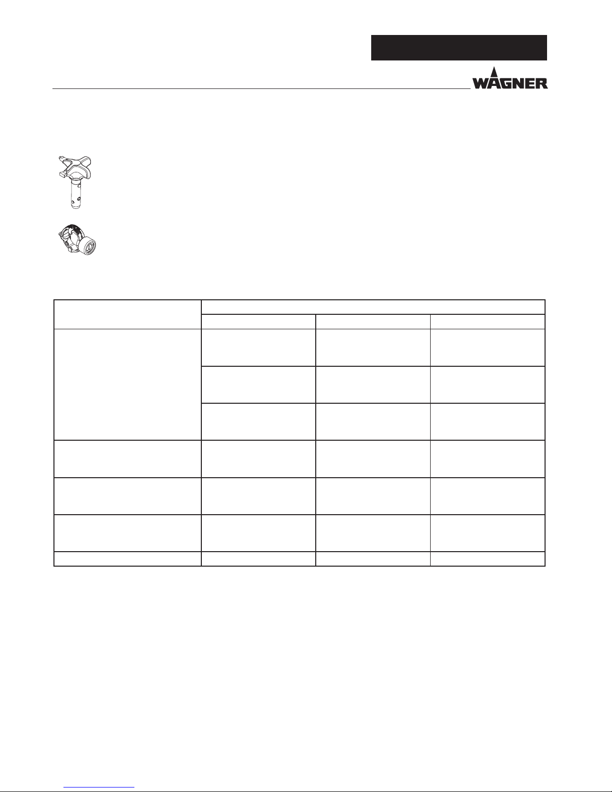
11.1 ZUBEHÖR FÜR SF 23 PRO
POS. BENENNUNG BESTELLNR.
1a
1b
1c
Spritzpistole Vector Pro (2 Finger)
Spritzpistole Vector Pro (4 Finger)
Spritzpistole Vector Grip (2 Finger und
4 Finger)
Spritzpistole AG-14
(Edelstahlausführung)
0538 041
0538 040
0538 043
0502 166
2 AirCoat Spritzpistole AC 4500 (blau) 2368 269
3 Doppelschlauch 9984 564
4 AirCoat-Regler Anbausatz 0340 250
5 HD-Schlauch DN6-PN270-1/4“NPSM-
15m
9984 574
6 Oberbehälter 5l 0341 265
7 Auslegerpistole
Länge 120 cm; G-Gewinde 7/8“
Länge 200 cm; G-Gewinde 7/8“
0296 441
0296 442
8 Inline Roller 0345 010
POS. BENENNUNG BESTELLNR.
9 Düsenverlängerung
Länge 15 cm
Länge 30 cm
Länge 45 cm
Länge 60 cm
0556 051
0556 052
0556 053
0556 054
10 Düsenverlängerung mit
Schwenkbarem Kniegelenk
Länge 100 cm
Länge 200 cm
Länge 300 cm
0096 015
0096 016
0096 017
11 Ansaugsystem (exibel)
2393 123
12 Manometer (HEA) 2383 995
13
Filterbeutel, Maschenweite 0,3 mm 0097 531
1a
7
5
9
10
811
2
3
4
6
12 13
1b 1c
Zubehör:
D
Page 23
23
Super Finish 23 Pro
ERSATZTEILE UND ZUBEHÖR
D
HEA-Düsen-Tabelle
i
Alle Düsen in der untenstehenden Tabelle werden zusammen mit dem passenden Pistolen lter geliefert.
Anwendung Düsenmarkierung Spritz-
winkel
Bohrung
inch / mm
Spritzbreite mm
1)
Pistolen lter Bestell-Nr.
Kunstharzlacke
PVC-Lacke
211
311
411
20°
30°
40°
0.011 / 0.28
0.011 / 0.28
0.011 / 0.28
120
150
190
Rot
Rot
Rot
0554211
0554311
0554411
Lacke, Vorlacke
Grundlacke, Füller
213
313
413
20°
30°
40°
0.013 / 0.33
0.013 / 0.33
0.013 / 0.33
120
150
190
Rot
Rot
Rot
0554213
0554313
0554413
Füller
Rostschutzfarben
415
515
615
40°
50°
60°
0.015 / 0.38
0.015 / 0.38
0.015 / 0.38
190
225
270
Gelb
Gelb
Gelb
0554415
0554515
0554615
Rostschutzfarben
Latexfarben
Dispersionen
417
517
617
40°
50°
60°
0.017 / 0.43
0.017 / 0.43
0.017 / 0.43
190
225
270
Weiß
Weiß
Weiß
0554417
0554517
0554617
Rostschutzfarben
Latexfarben
Dispersionen
519
619
50°
60°
0.019 / 0.48
0.019 / 0.48
225
270
Weiß
Weiß
0554519
0554619
Flammschutz 421
521
621
40°
50°
60°
0.021 / 0.53
0.021 / 0.53
0.021 / 0.53
190
225
270
Weiß
Weiß
Weiß
0554421
0554521
0554621
1)Spritzbreite bei etwa 30 cm Abstand zum Spritzobjekt und 100 bar (10 MPa) Druck mit Kunstharzlack 20 DIN-Sekunden.
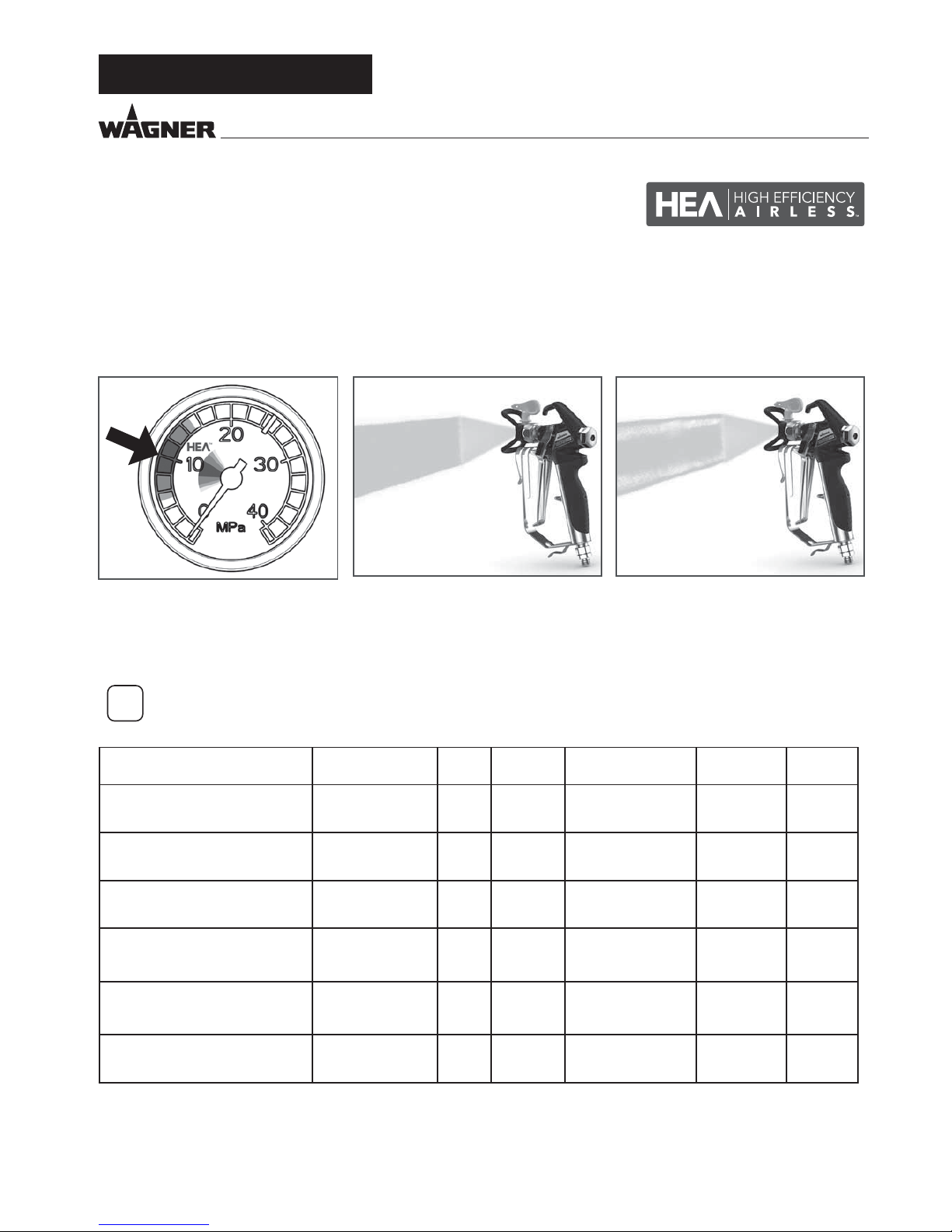
HEA DÜSEN FÜR NEBELARMES SPRITZEN MIT NIEDERDRUCK
HEA steht für High E ciency Airless, eine innovative Düsentechnologie, welche das Airless Spritzen revolutioniert. HEA Düsen
ermöglichen es den Druck des Spritzgerätes deutlich nach unten zu regulieren und im Niedrigdruckbereich zu arbeiten (idealerweise
bei 80 - 140 bar). Dabei können die Düsen mit allen TradeTip 3 Düsenhaltern und WAGNER Geräten verwendet werden.
Manche Farben müssen eventuell verdünnt werden, um ein optimales Ergebnis zu erzielen. Die Experten der Wagner
Anwendungstechnik haben deshalb eine Vielzahl von Materialien für Sie getestet. Die entsprechenden Empfehlungen nden
Sie im Wagner Spray Guide auf sprayguide.wagner-group.com .
Bei sichtbaren Kanten den Druck langsam erhöhen.
8
Gleichmäßiges Spritzbild ohne Spritzkanten.
9
Niedrigen Druck im HEA Bereich einstellen und starten.
Page 24

24
Super Finish 23 Pro
ERSATZTEILE UND ZUBEHÖR
D
Airless-Düsen-Tabelle
Wagner
TradeTip 3 Düse
bis 270 bar
(27 MPa)
ohne Düse
G-Gewinde (7/8 - 14 UNF)
Best.-Nr.
0289390
ohne Düse
F-Gewinde (11/16 - 16 UN)
Best.-Nr.
0289391
i
Alle Düsen in der untenstehenden Tabelle werden zusammen mit dem passenden Pistolen lter geliefert.
Anwendung Düsenmarkierung Spritz-
winkel
Bohrung
inch / mm
Spritzbreite mm
1)
Pistolen lter Bestell-Nr.
Wasserverdünnbare und lösemittelhaltige Lacke und Lackfarben,
Öle, Trennmittel
107
207
307
407
109
209
309
409
509
609
10°
20°
30°
40°
10°
20°
30°
40°
50°
60°
0.007 / 0.18
0.007 / 0.18
0.007 / 0.18
0.007 / 0.18
0.009 / 0.23
0.009 / 0.23
0.009 / 0.23
0.009 / 0.23
0.009 / 0.23
0.009 / 0.23
100
120
150
190
100
120
150
190
225
270
Rot
Rot
Rot
Rot
Rot
Rot
Rot
Rot
Rot
Rot
0553107
0553207
0553307
0553407
0553109
0553209
0553309
0553409
0553509
0553609
Kunstharzlacke
PVC-Lacke
111
211
311
411
511
611
10°
20°
30°
40°
50°
60°
0.011 / 0.28
0.011 / 0.28
0.011 / 0.28
0.011 / 0.28
0.011 / 0.28
0.011 / 0.28
100
120
150
190
225
270
Rot
Rot
Rot
Rot
Rot
Rot
0553111
0553211
0553311
0553411
0553511
0553611
Lacke, Vorlacke
Grundlacke
Füller
113
213
313
413
513
613
813
10°
20°
30°
40°
50°
60°
80°
0.013 / 0.33
0.013 / 0.33
0.013 / 0.33
0.013 / 0.33
0.013 / 0.33
0.013 / 0.33
0.013 / 0.33
100
120
150
190
225
270
330
Rot
Rot
Rot
Rot
Rot
Rot
Rot
0553113
0553213
0553313
0553413
0553513
0553613
0553813
Füller
Rostschutzfarben
115
215
315
415
515
615
715
815
10°
20°
30°
40°
50°
60°
70°
80°
0.015 / 0.38
0.015 / 0.38
0.015 / 0.38
0.015 / 0.38
0.015 / 0.38
0.015 / 0.38
0.015 / 0.38
0.015 / 0.38
100
120
150
190
225
270
300
330
Gelb
Gelb
Gelb
Gelb
Gelb
Gelb
Gelb
Gelb
0553115
0553215
0553315
0553415
0553515
0553615
0553715
0553815
Rostschutzfarben
Latexfarben
Dispersionen
117
217
317
417
517
617
717
817
10°
20°
30°
40°
50°
60°
70°
80°
0.017 / 0.43
0.017 / 0.43
0.017 / 0.43
0.017 / 0.43
0.017 / 0.43
0.017 / 0.43
0.017 / 0.43
0.017 / 0.43
100
120
150
190
225
270
300
330
Weiß
Weiß
Weiß
Weiß
Weiß
Weiß
Weiß
Weiß
0553117
0553217
0553317
0553417
0553517
0553617
0553717
0553817
Rostschutzfarben
Latexfarben
Dispersionen
219
319
419
519
619
719
819
919
20°
30°
40°
50°
60°
70°
80°
90°
0.019 / 0.48
0.019 / 0.48
0.019 / 0.48
0.019 / 0.48
0.019 / 0.48
0.019 / 0.48
0.019 / 0.48
0.019 / 0.48
120
150
190
225
270
300
330
385
Weiß
Weiß
Weiß
Weiß
Weiß
Weiß
Weiß
Weiß
0553219
0553319
0553419
0553519
0553619
0553719
0553819
0553919
Flammschutz 221
321
421
521
621
721
821
20°
30°
40°
50°
60°
70°
80°
0.021 / 0.53
0.021 / 0.53
0.021 / 0.53
0.021 / 0.53
0.021 / 0.53
0.021 / 0.53
0.021 / 0.53
120
150
190
225
270
300
330
Weiß
Weiß
Weiß
Weiß
Weiß
Weiß
Weiß
0553221
0553321
0553421
0553521
0553621
0553721
0553821
1)Spritzbreite bei etwa 30 cm Abstand zum Spritzobjekt und 100 bar (10 MPa) Druck mit Kunstharzlack 20 DIN-Sekunden.
Page 25

25
Super Finish 23 Pro
ERSATZTEILE UND ZUBEHÖR
D
Anwendung Düsenmarkierung Spritz-
winkel
Bohrung
inch / mm
Spritzbreite mm
1)
Pistolen lter Bestell-Nr.
Dachbeschichtung 223
323
423
523
623
723
823
20°
30°
40°
50°
60°
70°
80°
0.023 / 0.58
0.023 / 0.58
0.023 / 0.58
0.023 / 0.58
0.023 / 0.58
0.023 / 0.58
0.023 / 0.58
120
150
190
225
270
300
330
Weiß
Weiß
Weiß
Weiß
Weiß
Weiß
Weiß
0553223
0553323
0553423
0553523
0553623
0553723
0553823
Dickschichtmaterialien,
Korrosionsschutz,
Spritzspachtel
225
325
425
525
625
725
825
227
327
427
527
627
827
229
329
429
529
629
231
331
431
531
631
731
831
233
333
433
533
633
235
335
435
535
635
735
439
539
639
20°
30°
40°
50°
60°
70°
80°
20°
30°
40°
50°
60°
80°
20°
30°
40°
50°
60°
20°
30°
40°
50°
60°
70°
80°
20°
30°
40°
50°
60°
20°
30°
40°
50°
60°
70°
40°
50°
60°
0.025 / 0.64
0.025 / 0.64
0.025 / 0.64
0.025 / 0.64
0.025 / 0.64
0.025 / 0.64
0.025 / 0.64
0.027 / 0.69
0.027 / 0.69
0.027 / 0.69
0.027 / 0.69
0.027 / 0.69
0.027 / 0.69
0.029 / 0.75
0.029 / 0.75
0.029 / 0.75
0.029 / 0.75
0.029 / 0.75
0.031 / 0.79
0.031 / 0.79
0.031 / 0.79
0.031 / 0.79
0.031 / 0.79
0.031 / 0.79
0.031 / 0.79
0.033 / 0.83
0.033 / 0.83
0.033 / 0.83
0.033 / 0.83
0.033 / 0.83
0.035 / 0.90
0.035 / 0.90
0.035 / 0.90
0.035 / 0.90
0.035 / 0.90
0.035 / 0.90
0.039 / 0.99
0.039 / 0.99
0.039 / 0.99
120
150
190
225
270
300
330
120
150
190
225
270
330
120
150
190
225
270
120
150
190
225
270
300
330
120
150
190
225
270
120
150
190
225
270
300
190
225
270
Weiß
Weiß
Weiß
Weiß
Weiß
Weiß
Weiß
Weiß
Weiß
Weiß
Weiß
Weiß
Weiß
Weiß
Weiß
Weiß
Weiß
Weiß
Weiß
Weiß
Weiß
Weiß
Weiß
Weiß
Weiß
Weiß
Weiß
Weiß
Weiß
Weiß
Weiß
Weiß
Weiß
Weiß
Weiß
Weiß
Weiß
Weiß
Weiß
0553225
0553325
0553425
0553525
0553625
0553725
0553825
0553227
0553327
0553427
0553527
0553627
0553827
0553229
0553329
0553429
0553529
0553629
0553231
0553331
0553431
0553531
0553631
0553731
0553831
0553233
0553333
0553433
0553533
0553633
0553235
0553335
0553435
0553535
0553635
0553735
0553439
0553539
0553639
Heavy Duty Applikationen
243
443
543
643
445
545
645
451
551
651
252
455
555
655
261
461
561
661
263
463
565
665
267
467
20°
40°
50°
60°
40°
50°
60°
40°
50°
60°
20°
40°
50°
60°
20°
40°
50°
60°
20°
40°
50°
60°
20°
40°
0.043 / 1.10
0.043 / 1.10
0.043 / 1.10
0.043 / 1.10
0.045 /
1.14
0.045 / 1.14
0.045 / 1.14
0.051 / 1.30
0.051 / 1.30
0.051 / 1.30
0.052 / 1.32
0.055 /
1.40
0.055 / 1.40
0.055 / 1.40
0.061 / 1.55
0.061 / 1.55
0.061 / 1.55
0.061 / 1.55
0.063 / 1.60
0.063 / 1.60
0.065 /
1.65
0.065 / 1.65
0.067 / 1.70
0.067 / 1.70
120
190
225
270
190
225
270
190
225
270
120
190
225
270
120
190
225
270
120
190
225
270
120
190
Grün
Grün
Grün
Grün
Grün
Grün
Grün
Grün
Grün
Grün
Grün
Grün
Grün
Grün
Grün
Grün
Grün
Grün
Grün
Grün
Grün
Grün
Grün
Grün
0553243
0553443
0553543
0553643
0553445
0553545
0553645
0553451
0553551
0553651
0553252
0553455
0553555
0553655
0553261
0553461
0553561
0553661
0553263
0553463
0553565
0553665
0553267
0553467
1)Spritzbreite bei etwa 30 cm Abstand zum Spritzobjekt und 100 bar (10 MPa) Druck mit Kunstharzlack 20 DIN-Sekunden.
i
Alle Düsen in der untenstehenden Tabelle werden zusammen mit dem passenden Pistolen lter geliefert.
Page 26
26
Super Finish 23 Pro
D
ERSATZTEILE UND ZUBEHÖR
2SpeedTip
Die innovative Wendedüse von WAGNER vereint zwei
Düsenkerne in einer Düse.
2 Speed Tip Halterung
Best.-Nr. 0271065
Düsen-Tabelle
Objektgröße Farbmaterialien
Lack (L) Dispersionen (D) Spachtel (S)
Small
D5
Düsen: 111 / 415
Best.-Nr. 0271 062
S5
Düsen: 225 / 629
Best.-Nr. 0271 064
D7
Düsen: 113 / 417
Best.-Nr. 0271 063
L10
Düsen: 208 / 510
Best.-Nr. 0271 042
D10
Düsen: 111 / 419
Best.-Nr. 0271 045
S10
Düsen: 527 / 235
Best.-Nr. 0271 049
Medium
L20
Düsen: 210 / 512
Best.-Nr. 0271 043
D20
Düsen: 115 / 421
Best.-Nr. 0271 046
S20
Düsen: 539 / 243
Best.-Nr. 0271 050
Large
L30
Düsen: 212 / 514
Best.-Nr. 0271 044
D30
Düsen: 115 / 423
Best.-Nr. 0271 047
S30
Düsen: 543 / 252
Best.-Nr. 0271 051
X-Large
D40
Düsen: 117 / 427
Best.-Nr. 0271 048
Empfohlener Pistolen lter rot weiß -
Page 27

27
Super Finish 23 Pro
D
Page 28

28
Super Finish 23 Pro
ERSATZTEILE UND ZUBEHÖR
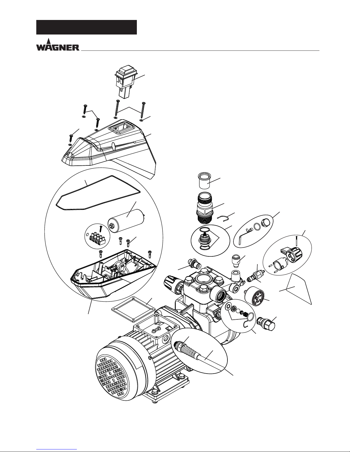
11.2 ERSATZTEILLISTE SF 23 PRO
POS. BESTELLNR BENENNUNG
1 9953696 Motorschutzschalter
2 2393002 Linsen-Blechschraube 4,2 x 45 (2 Stk.)
3 2393003 Linsen-Blechschraube 4,2 x 25 (2 Stk.)
4 2388381 Linsen-Blechschraube 4,2 x 22
5 2388377 Scheibe
6 2369533 Deckel
7 2304608 Rundschnur
8 2393015 Kondensator 25uf 400V kpl.
9 2393018 Linsenkopfschraube M4x18 (4 Stk)
10 2393035 Klemmkasten kpl. (Pos. 7-9)
11 2369517 Motordichtung
12 2369436 Doppelstutzen
14 2369454 Einlauf
15 2388291 Einlassventilgehäuse
16 2369455 Spange
17 2393043 Einlassventil kpl. (inkl. Pos 18)
18 2369458 Dichtring
19 2393044 Ölstandmesser
20 2369586 Stutzen
21 2393047 Entlastungsventilknopf kpl.
22 2369631 Entlastungsventil (inkl. Pos 23)
23 9971395 O-Ring
24 2398248 Frontlabel SF 23 Pro
25 0252475 Manometer kpl.
26 2393102 Auslassventilgehäuse kpl.
27 2393105 O-Ring und Dichtring
28 2393106 Auslassventil kpl. (inkl. Pos 27)
29 2388374 Kabelverschraubung
30 2394776 Geräteanschlusskabel
31 2400157 Netzkabel kpl. (Pos 29-30)
D
Page 29
29
Super Finish 23 Pro
1
2
3
4
5
6
8
9
11
7
10
14
15
16
18
17
20
12
21
22
23
25
26
27
28
19
24
30
31
29
ERSATZTEILE UND ZUBEHÖR
Ersatzteilbild SF 23 Pro
D
Page 30
30
Super Finish 23 Pro
ERSATZTEILE UND ZUBEHÖR
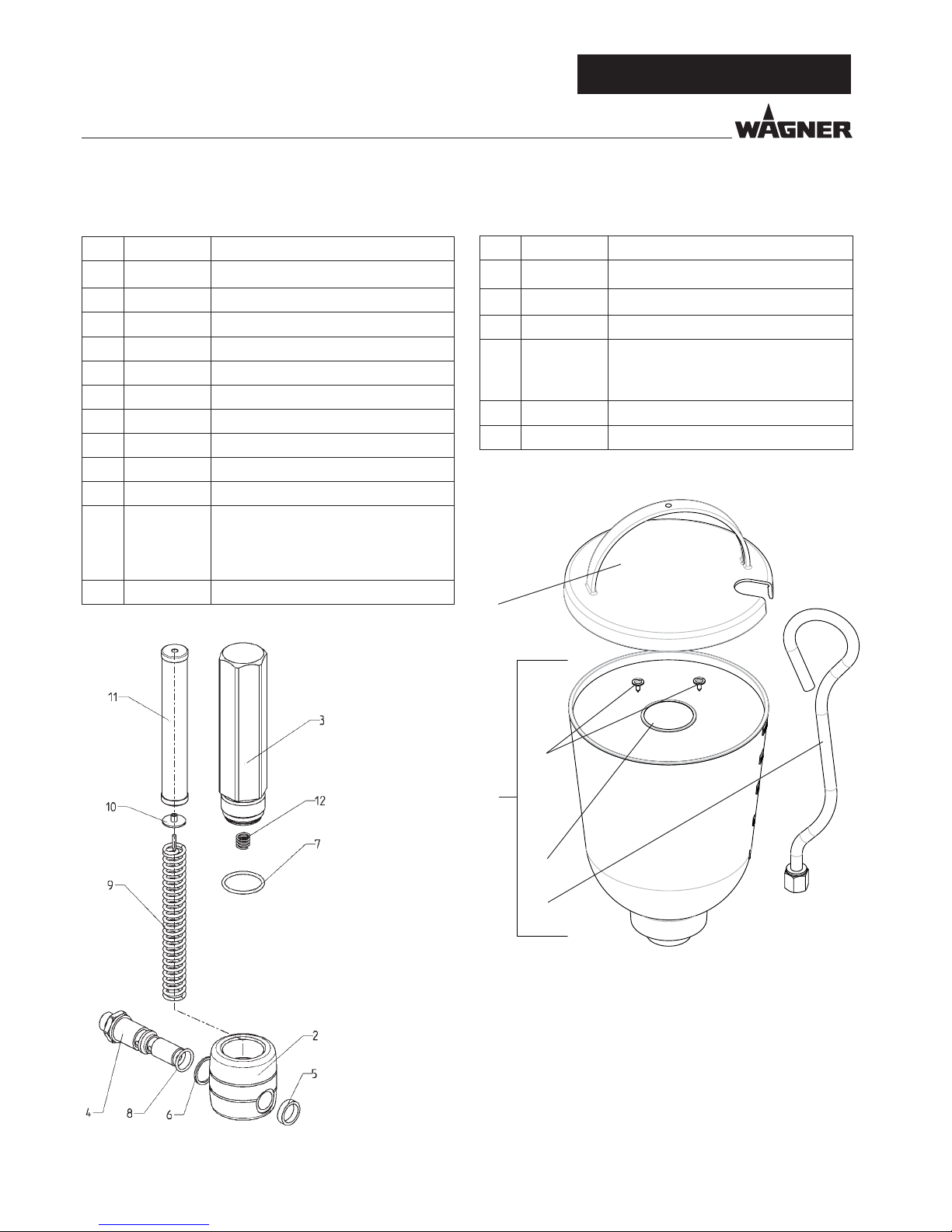
11.3 ERSATZTEILLISTE HOCHDRUCKFILTER
ZUBEHÖR
POS. BESTELLNR BENENNUNG
1 0097 123 Hochdrucklter HF- 01 kpl.
2 0097 301 Filterblock
3 0097 302 Filtergehäuse
4 0097 306 Hohlschraube
5 0097 304 Dichtring
6 9970 110 Dichtring
7 9974 027 O-Ring 30x2 (PTFE)
8 9971 401 O-Ring 16x2 (PTFE)
9 0508 749 Stützfeder
10 0508 603 Stützscheibe
11
0508 748
0508 450
0508 449
Filtereinsatz 60 Maschen
Optional:
Filtereinsatz 100 Maschen
Filtereinsatz 30 Maschen
12 9994 245 Druckfeder
Ersatzteilbild Hochdrucklter
POS. BESTELLNR BENENNUNG
1 0341 265 Oberbehälter 5l, kpl. (Pos. 2-6)
2 0340 901 Deckel
3 9902 306 Kombi-Blechschraube 3,9x13 (2)
4
0037 607
0003 756
Filterscheibe, Maschenweite 0,8 mm
Optional:
Filterscheibe, Maschenweite 0,4 mm
5 0340 904 Oberbehälter
6 0340 908 Rücklaufrohr
11.4 ERSATZTEILLISTE OBERBEHÄLTER
Ersatzteilbild Oberbehälter
4
3
2
5
6
D
Page 31

31
Super Finish 23 Pro
11.5 ERSATZTEILLISTE WAGEN
POS. BESTELLNR BENENNUNG
1 2369570 Deichsel
2 13806 Hülse
3 2396299 Halbhohlniete
4 2369585 Reinigungsbehälter
5 2393786 Halter Reinigungsbehälter
6 2369550 Wagenuntergestell
7 2369578 Dämpfungsfuß
8 9920304 Scheibe
9 2391181 Zylinderkopfschraube
10 2393118 Dämpfungsfuß kpl. (Pos. 7-9)
11 9900118 Sechskantschraube
12 2369545 Dämpfungsplatte
13 9920102 Scheibe
14 9910208 Sechskantmutter
15 2393119 Dämpfungsplatte kpl. (Pos. 11-14)
16 2369556 Rad
17 9994950 Radkappe
18 2393121 Rad kpl. (Pos. 16, 17)
19 2388543 Fuß
11.6 ERSATZTEILLISTE ANSAUGSYSTEM
POS. BESTELLNR BENENNUNG
2393123 Ansaugsystem kpl.
1 2390605 Ansaugschlauch kpl. (inkl. Filter)
2 2390606 Rücklaufschlauch kpl.
3 2323325 Ansauglter
Ersatzteilbild Ansaugsystem
Ersatzteilbild Wagen
1 2
3
1
2
3
4
6
7
8
9
11
12
1314
16
17
19
5
D
ERSATZTEILE UND ZUBEHÖR
Page 32

32
Super Finish 23 Pro
SERVICENETZ IN DEUTSCHLAND
D
SERVICENETZ IN DEUTSCHLAND
WAGNER KONTAKTNETZ DEUTSCHLAND, IM INTERNET ZU FINDEN UNTER: GO.WAGNERGROUP.COM/PROFI
Berlin
J. Wagner GmbH
Servicestützpunkt
Flottenstraße 28–42
13407 Berlin
T 030 - 41109386
F 030 - 41109387
Kassel
J. Wagner GmbH
Servicestützpunkt
Fliederweg 3
34305 Niedenstein
T 05624 - 925537
F 05624 - 925538
Ratingen
J. Wagner GmbH
Servicestützpunkt
Siemensstraße 6-10
40885 Ratingen
T 02102 - 31037
F 02102 - 34395
München
Jahnke GmbH
Rathausstraße 13
85640 Putzbrunn
T 089 - 6140022
F 089 - 6140433
email: info@airless.de
www.airless.de
Heidersdorf in Sachsen
J. Wagner GmbH
Servicestützpunkt
Olbernhauer Straße 11
09526 Heidersdorf
T 037361 - 15707
F 037361 - 15708
Nürnberg
Grimmer GmbH
Siemensstraße 16-18
91126 Rednitzhembach
T 09122 - 79473
F 09122 - 794750
email: info@grimmer-sc.de
www.grimmer-sc.de
Markdorf – Zentrale
J. Wagner GmbH
Otto-Lilienthal-Straße 18
88677 Markdorf
Postfach 11 20
88669 Markdorf
T 07544 - 505 - 0
F 07544 - 505-1200
www.wagner-group.com
Kundenzentrum
T 07544 - 505-1666
F 07544 - 505-1155
email: kundenzentrum@wagner-group.com
Technischer Service
T 0180 - 55924637
(14 Cent/Minute aus dem deutschen
Festnetz, Mobilfunk max. 42 Cent/Min)
Page 33

33
Super Finish 23 Pro
PRÜFUNG DES GERÄTES
Aus Gründen der Sicherheit empfehlen wir das Gerät bei Bedarf, jedoch mindestens alle 12 Monate, durch Sachkundige
daraufhin zu prüfen, ob ein sicherer Betrieb weiterhin gewährleistet ist.
Bei stillgelegten Geräten kann die Prüfung bis zur nächsten
Inbetriebnahme hinausgeschoben werden.
Zusätzlich sind auch alle (eventuell abweichende) nationalen
Prüfungs- und Wartungsvorschriften zu beachten.
Bei Fragen wenden Sie sich bitte an die Kundendienststellen
der Firma Wagner.
WICHTIGER HINWEIS ZUR PRODUKTHAFTUNG
Nach dem seit 01.10.1990 geltenden Produkthaftungsgesetz
haftet der Hersteller für sein Produkt bei Produktfehlern uneingeschränkt nur dann, wenn alle Teile vom Hersteller stammen oder von diesem freigegeben wurden, die Geräte sachgemäß montiert und betrieben werden. Bei Verwendung von
fremdem Zubehör und Ersatzteilen kann die Haftung ganz
oder teilweise entfallen, wenn die Verwendung des fremden
Zubehörs oder der fremden Ersatzteile zu einem Produktfehler führt. In extremen Fällen kann von den zuständigen Behörden (Berufsgenossenschaft und Gewerbeaufsichtsamt) der
Gebrauch des gesamten Geräts untersagt werden.
Mit original WAGNER Zubehör und Ersatzteilen haben Sie die
Gewähr, dass alle Sicherheitsvorschriften erfüllt sind.
ENTSORGUNGSHINWEIS
Gemäß der europäischen Richtlinie 2002/96/EG zur Entsorgung von Elektro- Altgeräten, und deren Umsetzung in nationales Recht, ist dieses Produkt nicht über den Hausmüll zu
entsorgen, sondern muss der umweltgerechten Wiederverwertung zugeführt werden!
Ihr Wagner - Altgerät wird von uns, bzw. unseren Handelsvertretungen zurückgenommen und für Sie umweltgerecht
entsorgt. Wenden Sie sich in diesem Fall an einen unserer
Service-Stützpunkte, bzw. Handelsvertretungen oder direkt
an uns.
GARANTIEERKLÄRUNG
(Stand 01.02.2009)
1. Garantieumfang
Alle Wagner Pro-Farbauftragsgeräte (im folgenden Produkte genannt) werden sorgfältig geprüft, getestet und
unterliegen den strengen Kontrollen der Wagner Qualitätssicherung. Wagner gibt daher ausschließlich dem gewerblichen oder beruichen Verwender, der das Produkt im autorisierten Fachhandel erworben hat (im folgenden „Kunde“
genannt), eine erweiterte Garantie für die im Internet unter
www.wagner-group.com/pro-guarantee aufgeführten Produkte.
Die Mängelhaftungsansprüche des Käufers aus dem Kaufvertrag mit dem Verkäufer sowie gesetzliche Rechte werden
durch diese Garantie nicht eingeschränkt.
Wir leisten Garantie in der Form, dass nach unserer Entscheidung das Produkt oder Einzelteile hiervon ausgetauscht oder
repariert werden oder das Gerät gegen Erstattung des Kaufpreises zurückgenommen wird. Die Kosten für Material und
Arbeitszeit werden von uns getragen. Ersetzte Produkte oder
Teile gehen in unser Eigentum über.
2. Garantiezeit und Registrierung
Die Garantiezeit beträgt 36 Monate, bei industriellem Gebrauch oder gleichzusetzender Beanspruchung wie insbesondere Schichtbetrieb oder bei Vermietung 12 Monate.
Für Benzin und Luft betriebene Antriebe gewähren wir ebenso 12 Monate.
Die Garantiezeit beginnt mit dem Tag der Lieferung durch den
autorisierten Fachhandel. Maßgebend ist das Datum auf dem
Original-Kaufbeleg.
Für alle ab 01.02.2009 beim autorisierten Fachhandel gekauften Produkte verlängert sich die Garantiezeit um 24 Monate,
wenn der Käufer diese Geräte innerhalb von 4 Wochen nach
dem Tag der Lieferung durch den autorisierten Fachhandel
entsprechend den nachfolgenden Bestimmungen registriert.
Die Registrierung erfolgt im Internet unter
www.wagner-group.com/pro-guarantee.
Als Bestätigung gilt das Garantiezertikat, sowie der OriginalKaufbeleg, aus dem das Datum des Kaufes hervorgeht. Eine
Registrierung ist nur dann möglich, wenn der Käufer sich mit
der Speicherung seiner dort einzugebenden Daten einverstanden erklärt.
Durch Garantieleistungen wird die Garantiefrist für das Produkt weder verlängert noch erneuert.
Nach Ablauf der jeweiligen Garantiezeit können Ansprüche
gegen und aus der Garantie nicht mehr geltend gemacht werden.
D
PRÜFUNG DES GERÄTES / HINWEIS ZUR PRODUKTHAFTUNG / ENTSORGUNGSHINWEIS / GARANTIEERKLÄRUNG
Page 34

34
Super Finish 23 Pro
3. Abwicklung
Zeigen sich innerhalb der Garantiezeit Fehler in Material, Verarbeitung oder Leistung des Geräts, so sind Garantieansprüche unverzüglich, spätestens jedoch in einer Frist von 2 Wochen geltend zu machen.
Zur Entgegennahme von Garantieansprüchen ist der autorisierte Fachhändler, welcher das Gerät ausgeliefert hat, berechtigt.
Die Garantieansprüche können auch bei unseren,
in der Bedienungsanleitung genannten, Servicedienststellen
geltend gemacht werden.
Das Produkt muss zusammen mit
dem Original-Kaufbeleg, der die Angabe des Kaufdatums
und der Produktbezeichnung enthalten muss, frei eingesandt
oder vorgelegt werden. Zur Inanspruchnahme der Garantieverlängerung muss zusätzlich das Garantiezertikat beigefügt
werden.
Die Kosten sowie das Risiko eines Verlustes oder einer Beschädigung des Produkts auf dem Weg zu oder von der Stelle, welche die Garantieansprüche entgegennimmt oder das instand
gesetzte Produkt wieder ausliefert, trägt der Kunde.
4. Ausschluss der Garantie
Garantieansprüche können nicht berücksichtigt werden
-
für Teile, die einem gebrauchsbedingten oder sonstigen,
natürlichen Verschleiß unterliegen, sowie Mängel am Produkt,
die auf einen gebrauchsbedingten oder sonstigen natürlichen
Verschleiß zurückzuführen sind. Hierzu zählen insbesondere
Kabel, Ventile, Packungen, Düsen, Zylinder, Kolben, Medium
führende Gehäuseteile, Filter, Schläuche, Dichtungen, Rotoren,
Statoren, etc.. Schäden durch Verschleiß werden insbesondere
verursacht durch schmirgeln-de Beschichtungsstoe, wie
beispielsweise Dispersionen, Putze, Spachtel, Kleber, Glasuren,
Quarzgrund.
-
bei Fehlern an Geräten, die auf Nichtbeachtung von
Bedienungshinweisen, ungeeignete oder unsachgemäße
Verwendung, fehlerhafte Montage, bzw. Inbetriebsetzung
durch den Käufer oder durch Dritte, nicht bestimmungsgemäßen Gebrauch, anomale Umweltbedingungen,
ungeeignete Beschichtungsstoffe, chemische,
elektrochemische oder elektrische Einüsse, sachfremde
Betriebsbedingungen, Betrieb mit falscher Netzspannung/
-Frequenz, Überlastung oder mangelnde Wartung oder Pege
bzw. Reinigung zurückzuführen sind.
-
bei Fehlern am Gerät, die durch Verwendung von Zubehör-,
Ergänzungs- oder Ersatzteilen verursacht wurden, die keine
Wagner-Originalteile sind.
-
bei Produkten, an denen Veränderungen oder Ergänzungen
vorgenommen wurden.
-
bei Produkten mit entfernter oder unlesbar gemachter
Seriennummer
-
bei Produkten, an denen von nicht autorisierten Personen
Reparaturversuche durchgeführt wurden.
-
bei Produkten mit geringfügigen Abweichungen von der SollBeschaenheit, die für Wert und Gebrauchstauglichkeit des
Geräts unerheblich sind.
-
bei Produkten, die teilweise oder komplett zerlegt worden
sind.
5. Ergänzende Regelungen
Obige Garantien gelten ausschließlich für Produkte, die in der
EU, GUS, Australien vom autorisierten Fachhandel gekauft
und innerhalb des Bezugslandes verwendet werden.
Ergibt die Prüfung, dass kein Garantiefall vorliegt, so geht die
Reparatur zu Lasten des Käufers.
Die vorstehenden Bestimmungen regeln das Rechtsverhältnis
zu uns abschließend. Weitergehende Ansprüche, insbesondere für Schäden und Verluste gleich welcher Art, die durch
das Produkt oder dessen Gebrauch entstehen, sind außer im
Anwendungsbereich des Produkthaftungsgesetzes ausgeschlossen.
Mängelhaftungsansprüche gegen den Fachhändler bleiben
unberührt.
Für diese Garantie gilt deutsches Recht Die Vertragssprache ist
deutsch. Im Fall, dass die Bedeutung des deutschen und eines
ausländischen Textes dieser Garantie voneinander abweichen,
ist die Bedeutung des deutschen Textes vorrangig.
J. Wagner GmbH
Division Professional Finishing
Otto Lilienthal Strasse 18
88677 Markdorf
Bundesrepublik Deutschland
Änderungen vorbehalten
EU Konformitätserklärung
Wir erklären in alleiniger Verantwortung, dass dieses Produkt
den folgenden einschlägigen Bestimmungen entspricht:
2006/42/EG, 2014/30/EU, 2011/65/EU, 2012/19/EU
Angewandte harmonisierte Normen:
EN 12621, EN ISO 12100, EN 1953, EN 60204-1, EN 61000-3-2,
EN 61000-3-11, EN 61000-6-1, EN 61000-6-3
Die EU Konformitätserklärung liegt dem Produkt bei.
Sie kann bei Bedarf mit der Bestellnummer 2398553
nachbestellt werden.
D
GARANTIEERKLÄRUNG
Page 35

35
Super Finish 23 Pro
Translation of the original operating instructions
GB
1
Never bring ngers, hands or other body parts into contact with the spray jet!
Never point the spray gun at yourself, other persons or animals.
Never use the spray gun without spray jet safety guard.
Do not treat a spray injury as a harmless cut. In case of injury to the skin by coating material
or solvents, consult a doctor for quick and correct treatment. Inform the doctor about the
coating material or solvent used.
2
The following points are to be observed in accordance with the operating manual
before every start-up:
1. Faulty units may not be used.
2. Secure a Wagner spray gun with the securing lever at the trigger guard.
3. Ensure earthing.
4. Check the permissible operating pressure of the high-pressure hose and spray gun.
5. Check all the connecting parts for leaks.
3
Instructions for regular cleaning and maintenance of the unit are to be observed
strictly.
Observe the following rules before any work on the unit and at every working
break:
1. Relieve the pressure from the spray gun and high-pressure hose.
2. Secure a Wagner spray gun with the securing lever at the trigger guard
3. Switch the unit o.
WARNING!
Attention, danger of injury by injection!
Airless units develop extremely high spray pressures.
Ensure safety!
Page 36

36
Super Finish 23 Pro
GB
CONTENTS
Contents
1 SAFETY REGULATIONS FOR AIRLESS SPRAYING 37
1.1 Flash point _________________________________ 37
1.2 Explosion protection _________________________ 37
1.3 Danger of explosion and re from sources of
ignition during spraying work _________________ 37
1.4 Danger of injury from the spray jet _____________ 37
1.5 Secure spray gun against unintended operation __ 37
1.6 Recoil of spray gun __________________________ 37
1.7 Breathing equipment as protection against
solvent vapors ______________________________ 37
1.8 Prevention of occupational illnesses ____________ 37
1.9 Max. operating pressure ______________________ 38
1.10 High-pressure hose _________________________ 38
1.11 Electrostatic charging
(formation of sparks or ames) ________________ 38
1.12 Use of units on building sites and workshops _____ 38
1.13 Ventilation when spraying in rooms ____________ 38
1.14 Suction installations _________________________ 38
1.15 Earthing of the object ________________________ 38
1.16 Cleaning the unit with solvents ________________ 38
1.17 Cleaning the unit ___________________________ 38
1.18 Work or repairs at the electrical equipment ______ 38
1.19 Work at electrical components _________________ 38
1.20 Setup on an uneven surface ___________________ 38
2 GENERAL VIEW OF APPLICATION ____________ 39
2.1 Application ________________________________ 39
2.2 Coating material ____________________________ 39
2.2.1 Coating materials with sharp-edged additional
materials __________________________________ 39
2.2.2 Filtering ___________________________________ 40
3. DESCRIPTION OF UNIT _____________________ 40
3.1 Airless process ______________________________ 40
3.2 Functioning of the unit _______________________ 40
3.3 Explanatory diagram _________________________ 41
3.4 Adjusting the handle ________________________ 42
3.5 Technical data ______________________________ 42
4 STARTUP _________________________________ 43
4.1 Unit with suction system _____________________ 43
4.2 Unit with upper hopper ______________________ 43
4.3 High pressure hose and spray gun ______________ 43
4.4 Connection to the mains network ______________ 43
4.5 Cleaning preserving agent when starting-up of
operation initially ___________________________ 44
4.6 Ventilate unit (hydraulic system) if the sound of
inlet valve is not audible ______________________ 44
4.7 Taking the unit into operation with
coating material ____________________________ 44
5 SPRAYING TECHNOLOGY ___________________ 45
6 HANDLING THE HIGHPRESSURE HOSE _______ 46
7 INTERRUPTION OF WORK ___________________ 46
8 CLEANING THE UNIT _______________________ 47
8.1 Cleaning the unit from the outside _____________ 48
8.2 Suction lter _______________________________ 48
8.3 High-pressure lter __________________________ 48
8.4 Cleaning the Airless spray gun _________________ 49
9 SERVICING ________________________________ 49
9.1 General servicing ___________________________ 49
9.2 High-pressure hose __________________________ 49
10 REPAIRS AT THE UNIT ______________________ 50
10.1 Inlet valve _________________________________ 50
10.2 Outlet valve ________________________________ 51
10.3 Pressure control valve ________________________ 51
10.4 Replacing the power cable ___________________ 52
10.5 Typical wear parts ___________________________ 52
10.6 Connection diagram _________________________ 53
10.7 Remedy in case of faults ______________________ 54
11 SPARE PARTS AND ACCESSORIES ____________ 55
11.1 Super Finish 23 Pro accessories ________________ 55
11.2 Spare parts list Super Finish 23 Pro _____________ 60
11.3 Spare parts list high-pressure lter _____________ 62
11.4 Spare parts list hopper _______________________ 62
11.5 Spare parts List Trolley _______________________ 63
11.6 Spare parts list suction system ________________ 63
Testing of the unit ________________________________ 64
Important information on product liability_____________ 64
Note on disposal __________________________________ 64
Guarantee declaration _____________________________ 64
CE - declaration___________________________________ 65
European service network _________________________ 132
Page 37

37
Super Finish 23 Pro
GB
1 SAFETY REGULATIONS FOR
AIRLESS SPRAYING
All local safety regulations in force must be observed.
The following sources are just a sample of those containing
safety requirements for Airless spraying.
a) The European Standard „Spray equipment for coating ma-
terials – safety regulations „ (EN 1953).
The following safety regulations are to be observed in order
to ensure safe handling of the Airless high-pressure spraying
unit.
1.1 FLASH POINT
Only spray coating materials with a ash point
of 21 °C or higher.
The ash point is the lowest temperature at
which vapors develop from the coating material. These vapors are sucient to form an
inammable mixture over the air above the
coating material.
1.2 EXPLOSION PROTECTION
Do not use the unit in work places which are
covered by the explosion protection regulations. The unit is not designed to be explosion protected. Do not operate the device in
explosive areas (zone 0, 1 and 2). Explosive areas are, for example, places where paints are
stored and locations in direct proximity to the
object being sprayed. Keep the device at least
3 m from the object you are spraying.
1.3 DANGER OF EXPLOSION AND FIRE FROM
SOURCES OF IGNITION DURING SPRAYING
WORK
There must be no sources of ignition such as,
for example, open res, lit cigarettes, cigars or
tobacco pipes, sparks, glowing wires, hot surfaces, etc. in the vicinity.
1.4 DANGER OF INJURY FROM THE SPRAY JET
Attention, danger of injury by injection!
Never point the spray gun at yourself, other
persons or animals.
Never use the spray gun without spray jet
safety guard.
The spray jet must not come into contact
with any part of the body.
In working with Airless spray guns, the high
spray pressures arising can cause very dangerous injuries. If contact is made with the
spray jet, coating material can be injected
into the skin. Do not treat a spray injury as a
harmless cut. In case of injury to the skin by
coating material or solvents, consult a doctor
for quick and correct treatment. Inform the
doctor about the coating material or solvent
used.
1.5 SECURE SPRAY GUN AGAINST UNINTENDED
OPERATION
Always secure the spray gun when mounting or dismounting
the tip and in case of interruption to work.
1.6 RECOIL OF SPRAY GUN
When using a high operating pressure, pulling the trigger guard can eect a recoil force
up to 15 N.
If you are not prepared for this, your hand can
be thrust backwards or your balance lost. This
can lead to injury.
1.7 BREATHING EQUIPMENT AS PROTECTION
AGAINST SOLVENT VAPORS
Wear breathing equipment during spraying work.
A breathing mask is to be made available to the user.
SAFETY REGULATIONS
1.8 PREVENTION OF OCCUPATIONAL ILLNESSES
Protective clothing, gloves and possibly skin protection cream
are necessary for the protection of the skin.
Observe the regulations of the manufacturer concerning coating materials, solvents and cleaning agents in preparation,
processing and cleaning units.
Page 38

38
Super Finish 23 Pro
GB
SAFETY REGULATIONS
1.9 MAX. OPERATING PRESSURE
The permissible operating pressure for the spray gun, spray
gun accessories, unit accessories and high-pressure hose
must not fall short of the maximum operating pressure of 25
MPa (250 bar or 3625 psi).
1.10 HIGHPRESSURE HOSE
Attention, danger of injury by injection! Wear
and tear and kinks as well as usage that is not
appropriate to the purpose of the device can
cause leakages to form in the high-pressure
hose. Liquid can be injected into the skin
through a leakage.
y High-pressure hoses must be checked thoroughly before
they are used.
y Replace any damaged high-pressure hose immediately.
y Never repair defective high-pressure hoses yourself!
y Avoid sharp bends and folds: the smallest bending radius
is about 20 cm.
y Do not drive over the high-pressure hose. Protect against
sharp objects and edges.
y Never pull on the high-pressure hose to move the device.
y Do not twist the high-pressure hose.
y Do not put the high-pressure hose into solvents. Use only
a wet cloth to wipe down the outside of the hose.
y Lay the high-pressure hose in such a way as to ensure that
it cannot be tripped over.
Only use WAGNER original-high-pressure
hoses in order to ensure functionality, safety
and durability.
1.11 ELECTROSTATIC CHARGING FORMATION OF
SPARKS OR FLAMES
Electrostatic charging of the unit may occur
during spraying due to the ow speed of
the coating material. These can cause sparks
and ames upon discharge. The unit must
therefore always be earthed via the electrical
system. The unit must be connected to an
appropriately-grounded safety outlet.
An electrostatic charging of spray guns and the high-pressure
hose is discharged through the high-pressure hose. For this
reason the electric resistance between the connections of the
high-pressure hose must be equal to or lower than 1 M.
1.12 USE OF UNITS ON BUILDING SITES AND
WORKSHOPS
The unit may only be connected to the mains network via a
special feeding point with a residual-current device with INF
≤ 30 mA.
1.13 VENTILATION WHEN SPRAYING IN ROOMS
Adequate ventilation to ensure removal of the solvent vapors
has to be ensured.
1.14 SUCTION INSTALLATIONS
The are to be provided by the unit user in accordance with the
corresponding local regulations.
1.15 EARTHING OF THE OBJECT
The object to be coated must be earthed.
(Building walls are usually earthed naturally)
1.16 CLEANING THE UNIT WITH SOLVENTS
When cleaning the unit with solvents, the
solvent should never be sprayed or pumped
back into a container with a small opening
(bunghole). An explosive gas/air mixture can
arise. The container must be earthed.
1.17 CLEANING THE UNIT
Danger of short-circuits caused by water ingression!
Never spray down the unit with high-pressure or high-pressure steam cleaners.
1.18 WORK OR REPAIRS AT THE ELECTRICAL
EQUIPMENT
These may only be carried out by a skilled electrician. No liability is assumed for incorrect installation.
1.19 WORK AT ELECTRICAL COMPONENTS
Unplug the power plug from the outlet before carrying out
any repair work.
Page 39

39
Super Finish 23 Pro
GB
SAFETY REGULATIONS/ GENERAL VIEW OF APPLICATION
2 GENERAL VIEW OF APPLICATION
2.1 APPLICATION
SF 23 Pro is an electric driven unit for the airless atomization of
dierent painting materials. Also it is able to feed the internal
feeded paint roller, which is available as accessory.
SF 23 Pro is made for jobs in the workshop and on the building site.
The SF 23 Pro’s device output is designed so that dispersions
can be processed indoors and outdoors for small to mediumsized objects.
When painting, the device is suitable for all kinds of typical
painting jobs, e.g.:
doors, door frames, balustrades, furniture, woodencladding,
fences, radiators (heating) and steel parts.
We recommend using the top container for paintwork.
2.2 COATING MATERIAL
Diluting lacquers and paints or those containing solvents, twocomponent coating materials, dispersion and latex paints.
No other materials should be used for spraying without WAGNER‘s approval.
Pay attention to the Airless quality of the
coating materials to be processed.
The unit is able to process coating materials with up to
20,000 mPas. If highly viscous coating materials cannot be tak-
en in or the performance of the unit is to low, the paint must
be diluted in accordance with the manufacturer‘s instructions.
Attention: Make sure, when stirring up with
motor-driven agitators that no air bubbles
are stirred in. Air bubbles disturb when spraying and can, in fact, lead to interruption of
operation.
2.2.1 COATING MATERIALS WITH SHARPEDGED
ADDITIONAL MATERIALS
These particles have a strong wear and tear eect on valves
and tips, but also on the heating hose and spray gun. This impairs the durability of these wearing parts considerably.
1.20 SETUP ON AN UNEVEN SURFACE
The front end must always point downwards in order to avoid
sliding away.
If possible do not use the unit on an inclined surface since the
unit tends to wander through the resulting vibrations.
Page 40

40
Super Finish 23 Pro
GB
GENERAL VIEW OF APPLICATION
2.2.2 FILTERING
Sucient ltering is required for fault-free operation. To this
purpose the unit is equipped with a suction lter (Item 1) and
an insertion lter in the spray gun (Item 2). Regular inspection of these lters for damage or soiling is urgently recommended.
A high-pressure lter (Item 3) -available as accessory- is rising
up the ltering surface and will make the work more comfortable.
3. DESCRIPTION OF UNIT
3.1 AIRLESS PROCESS
The main area of application are thick layers of highly viscous
coating material.
At the SF 23 Pro unit a diaphragm pump takes in the coating
materials and transports it via a high-pressure hose to the
spray gun with the airless tip. Here the coating material atomizes since it is pressed through the tip core at a maximum
pressure of 25 MPa (250 bar, 3625 psi). This high pressure has
the eect of micro ne atomisation of the coating material.
As no air is used in this process, it is described as an AIRLESS
process.
This method of spraying has the advantages of nest atomisation, cloudless operation (depending of a correct unit adjustment) and a smooth, bubblefree surface. As well as these, the
advantages of the speed of work and convenience must be
mentioned.
3.2 FUNCTIONING OF THE UNIT
The following section contains a brief description of the technical construction for better understanding of the function:
SF 23 Pro is an electrically driven high-pressure paint spraying
equipment.
The electric motor (1) drives the hydraulic pump via planetary
gears (2). A piston (3) is moved up and down so that hydraulic
oil is moved under the diaphragm (4) which then moves.
In detail:
The downwards movement of the machine opens the disk inlet valve (5) automatically and coating material is sucked in.
During the upwards movement of the diaphragm, the coating
material is displaced and the outlet valve opens while the inlet
valve is closed.
The coating material ows under high pressure through the
high-pressure hose to the spray gun and is atomized when it
exists from the tip.
The pressure control valve limits the set pressure in the hydraulic oil circuit and thus also the pressure of the coating
material.
A pressure change when the same tip is used also leads to a
change in the amount of paint atomized.
13
5
4
2
1
2
3
Page 41

41
Super Finish 23 Pro
6
1
2
3
7
9
10
8
4
5
12
9
14
11
4
15
16
13
GB
DESCRIPTION OF UNIT
3.3 EXPLANATORY DIAGRAM
1 Tip guard with airless tip*
2 Spray gun*
3 High-pressure hose*
4 Connection for high-pressure hose
5 Pressure gauge*
6 Pressure control valve
7 ON / OFF switch
8 Pressure relief valve
=
Spraying
=
Circulation
9 Return hose*
10 Suction hose*
11 Hopper*
12
Outlet valve
13 Oil dipstick
14 Cleaning Container
15 Hose bracket
16 Gun holder
17 Tool bag (no g.)
*Accessory. The actual scope of the delivery
depends on how the Spray Pack is congured.
Page 42

42
Super Finish 23 Pro
GB
DESCRIPTION OF UNIT
3.4 ADJUSTING THE HANDLE
Swing the handle (1) upwards (the sleeves fall downwards and
secure the handle in the terminal position).
Push the sleeves (2) upwards in order to swing the handle
down again if necessary.
2
1
Transportation in vehicle
Secure the unit in the vehicle by means of suitable fasteners.
The device can be placed on its side if necessary. In this case,
please ensure that no attachments can be damaged. Attention: Paint or solvent residues can escape from the connections!
3.5 TECHNICAL DATA
Voltage :
230 -240 V AC, 50 Hz
Fuses : 16 A time-lag
Unit connecting line : 6 m long, 3 x 1.5 mm²
Max. current consumption: 7.0 A
Degree of protection : IP 54
Rated input of device: 1.3 kW
Max. operating pressure : 25 MPa (250 bar)
Max. volume ow : 2.6 l/min
Volume ow at 12 MPa
(120 bar) with water :
2.3 l/min
Max. temperature of the
coating material :
43 °C
Max. viscosity : 20,000 mPas
Empty weight : 27 kg
Hydraulic oil lling
quantity :
Hydraulics housing
Gears (grease)
1.3 liter
45 g
Max. vibration at the spraygun : lower than 2.5 m/s²
Max. sound pressure level: 75 dB (A)*
*Place of measurement: 1 m distance from unit and 1.60
m above oor, 12 MPa (120 bar) operating pressure,
reverberant oor
Page 43

43
Super Finish 23 Pro
GB
STARTUP
4 STARTUP
4.1 UNIT WITH SUCTION SYSTEM
1. Ensure that the sealing surfaces of the connections are
clean.
Ensure that the red inlet (1) is inserted in the coating ma-
terial inlet (4).
2. Use the enclosed 41 mm wrench to screw the union nut
(2) at the suction hose (3) onto the coating material inlet
(4) and tighten it.
3. Screw the union nut (5) at the return hose (6) to the con-
nection (7) (22mm).
4.3 HIGH PRESSURE HOSE AND SPRAY GUN
1. Screw the high pressure hose (9) onto the hose connection
2. Screw the spray gun (10) onto the high pressure hose
3. Tighten all union nuts on high pressure hose so that no
coating material can escape.
4. Screw the tip holder with the selected tip onto the spray
gun, align tip and tighten union nut.
When unscrewing the high pressure hose,
hold rmly on the hose connection with a
22mm wrench.
4.2 UNIT WITH UPPER HOPPER
1. Ensure that the sealing surfaces of the connections are
clean. Ensure that the red inlet (1) is inserted in the coating material inlet (4).
2. Screw the union nut (5) on the return pipe (6) onto the
connection (7).
3. Screw the upper hopper (8) onto the coating material inlet (4).
4.4 CONNECTION TO THE MAINS NETWORK
Connection must always be carried out via
an appropriately grounded safety outlet with
residual-current-operated circuit-breaker.
Before connecting the unit to the mains supply, ensure that
the line voltage matches that specied on the unit’s rating
plate.
Press the inlet valve inside the coating material inlet (4) downwards before starting the
operation. This ensures that the valve is not
blocked or clogged.
1
4
2
3
5
6
7
1
4
5
6
7
8
9
9
10
10
Page 44

44
Super Finish 23 Pro
GB
STARTUP
4.5 CLEANING PRESERVING AGENT WHEN
STARTINGUP OF OPERATION INITIALLY
Unit with suction tube
1. Immerse the suction system into a container lled with a
suitable cleaning agent (recommendation: water).
Unit with hopper
2. Fill up hopper with a suitable cleaning agent (recommendation: water).
3. Set pressure relief valve (1) to
( circulation).
4. Switch the device on (Pos. I) using the ON/OFF switch (2).
5. Slowly turn the pressure regulating knob (3) to the right.
6. Wait until you can hear the sound of the inlet valve and
cleaning agent ows from the return hose.
7. Turn the pressure regulating knob (3) back approx. one
rotation.
8. Set pressure relief valve (1) to
(spray).
Pressure is rising up inside the high pressure hose (visible
at pressure gauge (4)).
9. Point the tip of the spray gun to inner wall of an open and
empty metal container and pull the trigger at the spray
gun.
10. The pressure is increased by turning the pressure regulating knob (3) to the right. Set approx. 10 MPa (100 bar) at
the pressure gauge.
11. Spray the cleaning agent out of the unit for approx.
1 - 2 min. (~5 litres) into the open collecting container.
4.7 TAKING THE UNIT INTO OPERATION WITH
COATING MATERIAL
Unit with suction tube
1. Immerse the suction system into a container lled with
coating material.
Unit with hopper
2. Fill coating material into the hopper.
3. Set pressure relief valve (1) to
( circulation).
4. Switch the device on (Pos. I) using the ON/OFF switch (2).
5. Slowly turn the pressure regulating knob (3) to the right.
When the noise of the valves changes, the unit is bled and
takes in coating material.
6. If coating material exits from the return hose, turn the
pressure regulating knob (3) back approx. 1 rotation.
7. Set pressure relief valve (1) to
(spray).
Pressure is rising up inside the high pressure hose (visible
at pressure gauge (4)).
8. Pull the trigger of the spray gun and spray into an open
and empty container in order to remove the remaining
cleaning agent from the unit. When coating materials exits from the tip, close the spray gun.
9. Adjust the spraying pressure by turning the pressure regulating knob (3).
10. The unit is ready to spray.
4.6 VENTILATE UNIT HYDRAULIC SYSTEM IF THE
SOUND OF INLET VALVE IS NOT AUDIBLE
1. Switch the device on (Pos. I) using the ON/OFF switch (2).
2. Turn pressure regulating knob (3) approx. three revolu-
tions to the left.
3. Set pressure relief valve (1) to
(circulation). The hydraulic system is ventilated. Leave the unit on for two to
three minutes.
4. Then slowly turn pressure regulating knob (3) to the right
until you can hear the sound of the inlet valve.
5. If not, repeat points 2 and 4
1
2
4
3
4
Page 45

45
Super Finish 23 Pro
GB
SPRAYING TECHNIQUE / HANDLING THE HIGHPRESSURE HOSE / INTERRUPTION OF WORK
5 SPRAYING TECHNIQUE
•
The key to a high-quality result is the even coating of the
entire surface. Move your arm at a uniform speed and hold
the spray gun at a constant distance from the surface. The
ideal distance is around 30 cm between the spray nozzle and
the surface. (Fig. A)
•
Hold the spray gun parallel to the surface. Move the gun using
your entire arm, not just the wrist. (Fig. B)
•
Hold the spray gun at right angles to the surface. Otherwise the
coating will be thicker at one end than the other. (Fig. C)
•
Pull the trigger guard once you have started the movement.
Release the trigger again before you nish the movement.
(Fig. D) Avoid interruptions within the spray surface.
•
Allow each stripe to overlap by around 30%. This will ensure
even coating. (Fig. E)
•
Use the lowest possible pressure setting to create the desired
spray pattern in order to minimise spray mist.
•
To achieve perfect surfaces at varnishing works, special
accessories are available at Wagner, e.g. FineFinish tips. Your
Wagner dealer will advise you.
30 cm
A)
B)
C)
30 cm
30 cm30 cm
D)
30% overlap
E)
Page 46

46
Super Finish 23 Pro
GB
SPRAYING TECHNIQUE / HANDLING THE HIGHPRESSURE HOSE / INTERRUPTION OF WORK
6 HANDLING THE HIGHPRESSURE
HOSE
The unit is equipped with a high-pressure hose specially suited for diaphragm pumps.
Danger of injury through leaking highpressure hose. Replace any damaged highpressure hose immediately.
Never repair defective high-pressure hoses
yourself!
The high-pressure hose is to be handled with care. Avoid sharp
bends and folds: the smallest bending radius is about 20 cm.
Do not drive over the high-pressure hose. Protect against
sharp objects and edges.
Never pull on the high-pressure hose to move the device.
Make sure that the high-pressure hose cannot twist. This can
be avoided by using a Wagner spray gun with a swivel joint
and a hose system.
When using the high-pressure hose while
working on scaolding, it is best to always
guide the hose along the outside of the scaffolding.
The risk of damage rises with the age of the
high-pressure hose.
Wagner recommends replacing high-pressure hoses after 6 years.
Only use WAGNER original-high-pressure
hoses with internal heating in order to ensure
functionality, safety and durability.
7 INTERRUPTION OF WORK
1. Set pressure relief valve to (pressure relief, circulation).
2. Switch the unit o using the ON/OFF switch (Pos. 0).
3. Pull trigger of the spray gun to decrease the pressure of
the high pressure hose and the spray gun.
3. Secure the spray gun, refer to the operating manual of the
spray gun.
4. Remove tip from tip holder and store the tip in a small vessel with suitable cleaning agent.
5. Leave the suction system immersed in the coating material or immerse it in the corresponding cleaning agent.
The suction lter and unit should not dry out.
6. Cover the material container in order to prevent the paint
from drying.
In using quick-drying or two-component
coating materials, do not fail to rinse unit
through with a suitable cleaning agent during the processing period.
Page 47

47
Super Finish 23 Pro
GB
DISPLAYS AT THE UNIT / CLEANING THE UNIT
8 CLEANING THE UNIT
A clean state is the best method of ensuring operation without problems. After you have nished spraying, clean the unit.
Under no circumstances may coating material rests dry and
harden in the unit. The cleaning agent used for cleaning (only
with a ash point above 21 °C) must be suitable for the coating material used.
Warm water improves the cleaning eect in
the case of water-dilutable coating materials.
• Secure the spray gun,
refer to the operating manual of
the spray gun.
Remove and clean the tip and tip holder.
• Unit with suction system
1. Set pressure relief valve to
(circulation).
2.
Switch the device on (Pos. I) using the ON/OFF switch.
3. Remove the suction system from the material container.
The return pipe hose remains over the material container
until barely any coating material comes out.
4. Immerse the suction system into a container lled with a
suitable cleaning agent
5. Turn the pressure control valve back in order to set a minimal spraying pressure.
6. Set pressure relief valve to
(spray).
7. Pull the trigger of the spray gun in order to pump the
remaining coating material from the suction hose, highpressure hose and the spray gun into an open container (if
appropriate, increase the pressure at the pressure control
valve slowly in order to obtain a higher material ow).
The container must be earthed in case of
coating materials which contain solvents (e.g.
by using a metal container).
Caution! Do not pump or spray in container
with small opening (bunghole)!
See safety regulations.
8. Set pressure relief valve to
(circulation).
9. Pump suitable cleaning agent in the circuit for several
minutes.
The cleaning eect is increased by alternatively opening and closing the spray gun.
10. Set pressure relief valve to
(spray).
11. Pump the remaining cleaning agent into an open container until the pump is empty.
12. Set pressure relief valve to
(circulation).
13. Switch the unit o using the ON/OFF switch (Pos. 0).
• Unit with upper hopper
1. Set pressure relief valve to
(circulation).
2. Switch the device on (Pos. I) using the ON/OFF switch.
3. Turn the pressure control valve back in order to set a minimal spraying pressure.
4. Set pressure relief valve to
(spray).
5. Pull the trigger of the spray gun in order to pump the remaining coating material from the hopper, high-pressure
hose and the spray gun into an open container (if appropriate, increase the pressure at the pressure control valve
slowly in order to obtain a higher material ow).
The container must be earthed in case of
coating materials which contain solvents (e.g.
by using a metal container).
Caution! Do not pump or spray in container
with small opening (bunghole)!
See safety regulations.
6. Fill up hopper with suitable cleaning agent.
7. Set pressure relief valve to
(circulation).
8. Pump suitable cleaning agent in the circuit for several
minutes.
9. Set pressure relief valve to
(spray).
10. Pump the remaining cleaning agent from the hopper,
high-pressure hose and the spray gun into an open container
11. Set pressure relief valve to
(circulation).
12. Switch the unit o using the ON/OFF switch (Pos. 0).
Page 48

48
Super Finish 23 Pro
GB
CLEANING THE UNIT
8.1 CLEANING THE UNIT FROM THE OUTSIDE
First unplug the power plug from the outlet.
Danger of short-circuits caused by water
ingression! Never spray down the unit with
high-pressure or high-pressure steam cleaners.
Do not put the high-pressure hose into solvents. Use only a wet cloth to wipe down the
outside of the hose.
Wipe down unit externally with a cloth which has been immersed in a suitable cleaning agent.
8.2 SUCTION FILTER
Clean lters always ensure maximum volume,
constant spray pressure and problem-free
functioning of the unit.
Unit with suction system
1. Unscrew the lter (Item 1) from the suction tube.
2. Clean or replace the lter.
Carry out cleaning with a hard brush and a corresponding
cleaning agent.
8.3 HIGHPRESSURE FILTER
1. Set pressure relief valve to
(pressure relief, circulation).
2. Switch the unit o using the ON/OFF switch (Pos. 0).
3. Open the high-pressure lter and clean the lter insert. To
do so:
4. Unscrew the lter housing (1) by hand.
5. Remove the lter insert (2) and pull out the bearing spring
(3).
6. Clean all the parts with the corresponding cleaning agent.
If compressed air is available – blow through the lter insert and bearing spring.
7. When mounting the lter ensure that the bearing ring (4)
in the lter insert is positioned correctly and check the Oring at the lter housing for damage.
8. Screw on the lter housing by hand until it stops (a higher
tightening force only impedes later dismantling).
1
2
suction system hopper
Unit with hopper
1. Release screws with a screwdriver (Item 2).
2. Lift and remove lter disk with a screwdriver
3. Clean or replace the lter disk.
Carry out cleaning with a hard brush and a corresponding
cleaning agent.
1
Page 49

49
Super Finish 23 Pro
GB
CLEANING THE UNIT / SERVICING
9.1 GENERAL SERVICING
We strongly recommend having an annual
check carried out by technicians for safety
reasons. Please observe all the applicable national regulations.
Minimum check before every startup:
1. Check the high-pressure hose, spray gun with rotary joint,
power supply cable with plug for damage.
2. Check whether the pressure gauge can be read.
Check at periodical intervals:
1. Check inlet and outlet valve according wear. Clean it and
replace worn out parts.
2. Check all lter inserts (spray gun, suction system) clean it
and replace if necessary.
9 SERVICING
9.2 HIGHPRESSURE HOSE
Inspect the high-pressure hose visually for any notches or
bulges, in particular at the transition in the ttings. It must be
possible to turn the union nuts freely. A conductivity of less
than
1 MΩ must exist across the entire length.
Have all the electric tests carried by the Wagner Service.
The risk of damage rises with the age of the
high-pressure hose.
Wagner recommends replacing high-pressure hoses after 6 years.
8.4 CLEANING THE AIRLESS SPRAY GUN
1. Rinse the Airless spray gun with a suitable cleaning agent
under lower operating pressure.
2. Clean the tip thoroughly with a suitable cleaning agent so
that no suitable coating material rests remain.
3. Do not store the tip in solvent because this reduces the
durability considerably.
4. Clean the outside of the Airless spray gun thoroughly.
1.
Unclip the top of the trigger guard (1) from the gun head.
2. Using the bottom of the trigger guard as a wrench, loosen
and remove the handle assembly (2) from the gun head.
3. Pull the old lter (3) out of the gun head. Clean or replace.
4. Slide the new lter, tapered end rst, into the gun head.
5. Thread the handle assembly into the gun head. Tighten
with the trigger wrench.
6. Snap the trigger guard back onto the gun head.
Insertion lter in the Airless spray gun
1
3
2
Page 50

50
Super Finish 23 Pro
GB
REPAIRS AT THE UNIT
10 REPAIRS AT THE UNIT
Switch the unit o.
Before all repair work: Unplug the power
plug from the outlet.
10.1 INLET VALVE
Disassembly
1. Place the enclosed 30 mm wrench on the housing (1).
2. Loosen the housing (1) with light blows of a hammer on
the end of the wrench.
3. Screw out the housing with the inlet valve (2) from the
paint section.
4. Pull of the clasp (3) using the enclosed screwdriver.
5. Place the enclosed 30 mm wrench on the inlet valve (2).
Turn out the inlet valve carefully.
6. Clean the valve seat (4) with a cleaning agent and brush
(ensure that no brush hairs are left behind).
7. Clean the seals (5, 6) and check for damage. Replace, if
necessary.
8. Check all the valve parts for damage. In case of visible
wear replace the inlet valve.
Installation
1. Insert the inlet valve (2) into the housing (1) and secure
with the clasp (3). Ensure that the (black) seal (5) is mounted in the housing.
2. Screw the unit from the housing and the inlet valve into
the paint section. The same (black) seal (6) has to be
mounted in the paint section.
3. Tighten the housing with the 30 mm wrench and tighten with three light blows of the hammer on the end of
the wrench. (Corresponds to approx. 90 Nm tightening
torque).
1
3
2
5
6
4
Page 51

51
Super Finish 23 Pro
GB
REPAIRS AT THE UNIT
10.3 PRESSURE CONTROL VALVE
Only have the pressure control valve (1) replaced by the customer service.
The max. operating pressure has to be reset
by the customer service.
1
10.2 OUTLET VALVE
1. Use a 22 mm wrench to screw the outlet valve from the
paint section.
2. Carefully remove the clasp (1) using the enclosed screwdriver. The pressure spring (2) pushes out ball (4) and
valve seat (5).
3. Clean or replace the components.
4. Check the O-ring (7) for damage.
5. Check the installation position when mounting the spring
support ring (3) (clipped onto spring (2)), outlet valve seat
(5) and seal (6), refer to gure.
Please also pay particular attention to the following notes:
1.
The torque for tting the outlet valve is 50 Nm.
2. During normal operation, check regularly whether the
outlet valve has become loose.
3. Always also replace the seal (6) if you have dismantled the
outlet valve, regardless of which component you want to
replace. Note: The seal (6) is located inside the paint section.
4. The groove in the seal (6) points outwards when replaced.
1
7
2
3
4
5
6
Page 52

52
Super Finish 23 Pro
GB
REPAIRS AT THE UNIT
10.4 REPLACING THE POWER CABLE
This may only be carried out by a skilled electrician. No liability is assumed for incorrect
installation.
Switch the unit o.
Before all repair work: Unplug the power
plug from the outlet.
1.
Remove the cover (1) by loosening the screws.
2. Loosen the cable threaded joint (2).
3. Loosen the wires (3).
4. Replace the unit connecting line.
(only an approved power cable with the designation H07-
RNF with a splash-proof plug may be used).
5. Connect the green/yellow wire to the contact with the PE
sign.
6. Remount the covers carefully (do not squeeze any cables!)
10.5 TYPICAL WEAR PARTS
Despite the use of high-quality materials the highly abrasive
eect of the paints means that wear can occur at the following parts:
Inlet valve (spare part Order No.: 2393043)
For replacing refer to Section 10.1
(failure becomes noticeable through performance loss and/or
poor or no suction)
Outlet valve (spare part Order No.: 2393106)
For replacing refer to Section 10.2
(failure becomes noticeable through performance loss and/
or poor suction) The outlet valve is usually considerably more
durable than the inlet valve. Thorough cleaning may already
help here.
1
2
3
Page 53

53
Super Finish 23 Pro
POWER CABLE
230V / 50Hz
TERMINAL STRIP
green/yellow
blue
light blue
brown
MOTOR
WITH TEMPERATURE SWITCH
M
1~
Z2
U2
OPERATION CAPACITOR
C = 25µF
400V
CMBDL
155°C
N
L
Z1
red
HSFFOyellow
blue
black
N
MOTOR SWITCH 8A
b
U<
P1
P2
6
3
light blue
blue
black
340380
254518
254519
b
GB
REPAIRS AT THE UNIT
10.7 CONNECTION DIAGRAM
Page 54

54
Super Finish 23 Pro
GB
REPAIRS AT THE UNIT
10.7 REMEDY IN CASE OF FAULTS
TYPE OF MALFUNCTION WHAT ELSE? POSSIBLE CAUSE MEASURES FOR ELIMINATING THE MALFUNCTION
Unit does not start The device does
not start after it has
been plugged in and
switched on.
No voltage applied Check voltage supply
Unit fuse has triggered Let the motor cool down
Capacitor in terminal box
burned out
Replace capacitor
Unit does not suck in Air bubbles do not exit
at the return hose
Inlet/outlet valve clogged
/ worn
Remove the valves and clean then (-> refer to
Section Pkt.10.1/10.2) / replace worn parts
Pressure control valve
turned down completely
Turn the pressure control valve to the right until the stop is reached
Air bubbles exit from
the return hose
Unit is sucking in outside
air
Check if Suction system is properly tightened
Check if red inlet is installed in the inlet valve
housing (-> see 4.1)
Check if the inlet valve housing is tightned
enough.
Unit does not generate pressure
Unit has sucked in Air in the oil circuit
(Possible reasons: long
time not used, replacement of diaphragm or
hydraulic oil change
Vent the hydraulic system (-> see 4.6)
Unit reached pressure, but the pressure
collapses, also at the
pressure gauge, during
spraying.
Suction lter clogged Check the suction lter. If necessary, clean/
replace
Paint cannot be worked in
this state. Due to its properties the paint clogs the
valves (inlet valve) and the
delivery rate is too low.
Dilute the paint
Unit reached pressure,
but the pressure collapses during spraying.
pressure gage still
shows high pressure
Clogged lter do not let
enough paint pass
Check/clean the (high-pressure lter) gun lter
Tip clogged Clean the tip
Unit does not generate
the max. pressure possible. Paint nevertheless exits at the return
hose.
Relief valve defective Please contact Wager Customer Service
After a longer period
of time, the pressure
drops or the performance of the suction
tube decreases (although all connected
lters are not blocked).
Inlet valve worn Replace inlet valve
Outlet valve worn Replace outlet valve
Tip worn Replace tip
Page 55

55
Super Finish 23 Pro
SPARE PARTS AND ACCESSORIES
GB
11 SPARE PARTS AND ACCESSORIES
11.1 SUPER FINISH 23 PRO ACCESSORIES
ITEM DESIGNATION ORDER NO.
1a
1b
1c
Spray gun Vector Pro (2-nger)
Spray gun Vector Pro (4-nger)
Spray gun Vector Pro (2-nger and
4-nger)
Spray gun AG-14
(stainless steel)
0538 041
0538 040
0538 043
0502 166
2 AirCoat spray gun AC 4500 (blue)
2368 269
3 Double hose 9984 564
4 AirCoat-controler set 0340 250
5 HP hose DN
6-PN270-1/4“NPSM-15m 9984 574
6 Hopper 5l 0341 265
7 Pole gun
Length 120cm; G thread 7/8”
Length 200cm; G thread 7/8”
0296 441
0296 442
8 Inline Roller 0345 010
ITEM DESIGNATION ORDER NO.
9 Tip extension
Length 15 cm
Length 30 cm
Length 45 cm
Length 60 cm
0556 051
0556 052
0556 053
0556 054
10 Tip extension with
Slewable knee joint
Length 100 cm
Length 200 cm
Length 300 cm
0096 015
0096 016
0096 017
11 Suction system (exible)
2393 123
12 Pressure gauge (HEA) 2383 995
13 Filter bag, mesh width 0,3 mm 0097 531
Accessories:
1a
7
5
9
10
811
2
3
4
6
12 13
1b 1c
Page 56

56
Super Finish 23 Pro
SPARE PARTS AND ACCESSORIES
GB
HEA NOZZLES FOR LOWMIST SPRAYING AT LOW PRESSURE
HEA stands for High E ciency Airless, an innovative nozzle technology revolutionising airless spraying. HEA nozzles allow the
pressure of the spray device to be reduced right down and allow it to work in the low-pressure range (ideally at 80 - 140 bar).
The nozzles can be used with all TradeTip 3 nozzle holders and WAGNER devices.
Some paints may need to be diluted to achieve the best result possible. The experts at Wagner application technology have
therefore tested a wide range of materials for you. Their recommendations can be found in the Wagner Spray Guide at sprayguide.
wagner-group.com.
If edges are visible, slowly increase the
pressure.
8
Even spray pattern without spray edges.
9
Set the low pressure in the HEA range
and start.
HEA tip table
i
All of the tips in the table below are supplied together with the appropriate gun lter.
Application Tip marking Spray
angle
Bore
inch / mm
Spraying
width mm 1)
Gun lter Order no.
Synthetic-resin paints
PVC paints
211
311
411
20°
30°
40°
0.011 / 0.28
0.011 / 0.28
0.011 / 0.28
120
150
190
red
red
Rot
0554211
0554311
0554411
Paints, primers
Fillers
213
313
413
20°
30°
40°
0.013 / 0.33
0.013 / 0.33
0.013 / 0.33
120
150
190
red
red
red
0554213
0554313
0554413
Fillers
Rust protection paints
415
515
615
40°
50°
60°
0.015 / 0.38
0.015 / 0.38
0.015 / 0.38
190
225
270
yellow
yellow
yellow
0554415
0554515
0554615
Rust protection paints
Latex paints
Dispersions
417
517
617
40°
50°
60°
0.017 / 0.43
0.017 / 0.43
0.017 / 0.43
190
225
270
white
white
white
0554417
0554517
0554617
Rust protection paints
Latex paints
Dispersions
519
619
50°
60°
0.019 / 0.48
0.019 / 0.48
225
270
white
white
0554519
0554619
Flame retardant 421
521
621
40°
50°
60°
0.021 / 0.53
0.021 / 0.53
0.021 / 0.53
190
225
270
white
white
white
0554421
0554521
0554621
1) Spray width at about 30 cm to the object and 100 bar (10 MPa) pressure with synthetic-resin paint 20 DIN seconds.
Page 57

57
Super Finish 23 Pro
Airless tip table
Wagner
TradeTip 3 tip
up to 270 bar
(27 MPa)
without tip
G thread (7/8 - 14 UN)
Order no.
0289390
without tip
F thread (11/16 - 16 UN)
Order no.
0289391
i
All of the tips in the table below are supplied together with the appropriate gun lter.
Application Tip marking Spray
angle
Bore
inch / mm
Spraying
width mm 1)
Gun lter Order no.
Water-thinnable and solventbased paints and varnishes, oils,
separating agents
107
207
307
407
109
209
309
409
509
609
10°
20°
30°
40°
10°
20°
30°
40°
50°
60°
0.007 / 0.18
0.007 / 0.18
0.007 / 0.18
0.007 / 0.18
0.009 / 0.23
0.009 / 0.23
0.009 / 0.23
0.009 / 0.23
0.009 / 0.23
0.009 / 0.23
100
120
150
190
100
120
150
190
225
270
red
red
red
red
red
red
red
red
red
red
0553107
0553207
0553307
0553407
0553109
0553209
0553309
0553409
0553509
0553609
Synthetic-resin paints
PVC paints
111
211
311
411
511
611
10°
20°
30°
40°
50°
60°
0.011 / 0.28
0.011 / 0.28
0.011 / 0.28
0.011 / 0.28
0.011 / 0.28
0.011 / 0.28
100
120
150
190
225
270
red
red
red
red
red
red
0553111
0553211
0553311
0553411
0553511
0553611
Paints, primers
Fillers
113
213
313
413
513
613
813
10°
20°
30°
40°
50°
60°
80°
0.013 / 0.33
0.013 / 0.33
0.013 / 0.33
0.013 / 0.33
0.013 / 0.33
0.013 / 0.33
0.013 / 0.33
100
120
150
190
225
270
330
red
red
red
red
red
red
red
0553113
0553213
0553313
0553413
0553513
0553613
0553813
Fillers
Rust protection paints
115
215
315
415
515
615
715
815
10°
20°
30°
40°
50°
60°
70°
80°
0.015 / 0.38
0.015 / 0.38
0.015 / 0.38
0.015 / 0.38
0.015 / 0.38
0.015 / 0.38
0.015 / 0.38
0.015 / 0.38
100
120
150
190
225
270
300
330
yellow
yellow
yellow
yellow
yellow
yellow
yellow
yellow
0553115
0553215
0553315
0553415
0553515
0553615
0553715
0553815
Rust protection paints
Latex paints
Dispersions
117
217
317
417
517
617
717
817
10°
20°
30°
40°
50°
60°
70°
80°
0.017 / 0.43
0.017 / 0.43
0.017 / 0.43
0.017 / 0.43
0.017 / 0.43
0.017 / 0.43
0.017 / 0.43
0.017 / 0.43
100
120
150
190
225
270
300
330
white
white
white
white
white
white
white
white
0553117
0553217
0553317
0553417
0553517
0553617
0553717
0553817
Rust protection paints
Latex paints
Dispersions
219
319
419
519
619
719
819
919
20°
30°
40°
50°
60°
70°
80°
90°
0.019 / 0.48
0.019 / 0.48
0.019 / 0.48
0.019 / 0.48
0.019 / 0.48
0.019 / 0.48
0.019 / 0.48
0.019 / 0.48
120
150
190
225
270
300
330
385
white
white
white
white
white
white
white
white
0553219
0553319
0553419
0553519
0553619
0553719
0553819
0553919
Flame retardant 221
321
421
521
621
721
821
20°
30°
40°
50°
60°
70°
80°
0.021 / 0.53
0.021 / 0.53
0.021 / 0.53
0.021 / 0.53
0.021 / 0.53
0.021 / 0.53
0.021 / 0.53
120
150
190
225
270
300
330
white
white
white
white
white
white
white
0553221
0553321
0553421
0553521
0553621
0553721
0553821
1)Spray width at about 30 cm to the object and 100 bar (10 MPa) pressure with synthetic-resin paint 20 DIN seconds.
GB
SPARE PARTS AND ACCESSORIES
Page 58

58
Super Finish 23 Pro
Application Tip marking Spray
angle
Bore
inch / mm
Spraying
width mm 1)
Gun lter Order no.
Roof coatings 223
323
423
523
623
723
823
20°
30°
40°
50°
60°
70°
80°
0.023 / 0.58
0.023 / 0.58
0.023 / 0.58
0.023 / 0.58
0.023 / 0.58
0.023 / 0.58
0.023 / 0.58
120
150
190
225
270
300
330
white
white
white
white
white
white
white
0553223
0553323
0553423
0553523
0553623
0553723
0553823
Thick- lm materials,
Corrosion protection
Spray ller
225
325
425
525
625
725
825
227
327
427
527
627
827
229
329
429
529
629
231
331
431
531
631
731
831
233
333
433
533
633
235
335
435
535
635
735
439
539
639
20°
30°
40°
50°
60°
70°
80°
20°
30°
40°
50°
60°
80°
20°
30°
40°
50°
60°
20°
30°
40°
50°
60°
70°
80°
20°
30°
40°
50°
60°
20°
30°
40°
50°
60°
70°
40°
50°
60°
0.025 / 0.64
0.025 / 0.64
0.025 / 0.64
0.025 / 0.64
0.025 / 0.64
0.025 / 0.64
0.025 / 0.64
0.027 / 0.69
0.027 / 0.69
0.027 / 0.69
0.027 / 0.69
0.027 / 0.69
0.027 / 0.69
0.029 / 0.75
0.029 / 0.75
0.029 / 0.75
0.029 / 0.75
0.029 / 0.75
0.031 / 0.79
0.031 / 0.79
0.031 / 0.79
0.031 / 0.79
0.031 / 0.79
0.031 / 0.79
0.031 / 0.79
0.033 / 0.83
0.033 / 0.83
0.033 / 0.83
0.033 / 0.83
0.033 / 0.83
0.035 / 0.90
0.035 / 0.90
0.035 / 0.90
0.035 / 0.90
0.035 / 0.90
0.035 / 0.90
0.039 / 0.99
0.039 / 0.99
0.039 / 0.99
120
150
190
225
270
300
330
120
150
190
225
270
330
120
150
190
225
270
120
150
190
225
270
300
330
120
150
190
225
270
120
150
190
225
270
300
190
225
270
white
white
white
white
white
white
white
white
white
white
white
white
white
white
white
white
white
white
white
white
white
white
white
white
white
white
white
white
white
white
white
white
white
white
white
white
white
white
white
0553225
0553325
0553425
0553525
0553625
0553725
0553825
0553227
0553327
0553427
0553527
0553627
0553827
0553229
0553329
0553429
0553529
0553629
0553231
0553331
0553431
0553531
0553631
0553731
0553831
0553233
0553333
0553433
0553533
0553633
0553235
0553335
0553435
0553535
0553635
0553735
0553439
0553539
0553639
Heavy duty applications
243
443
543
643
445
545
645
451
551
651
252
455
555
655
261
461
561
661
263
463
565
665
267
467
20°
40°
50°
60°
40°
50°
60°
40°
50°
60°
20°
40°
50°
60°
20°
40°
50°
60°
20°
40°
50°
60°
20°
40°
0.043 / 1.10
0.043 / 1.10
0.043 / 1.10
0.043 / 1.10
0.045 /
1.14
0.045 / 1.14
0.045 / 1.14
0.051 / 1.30
0.051 / 1.30
0.051 / 1.30
0.052 / 1.32
0.055 /
1.40
0.055 / 1.40
0.055 / 1.40
0.061 / 1.55
0.061 / 1.55
0.061 / 1.55
0.061 / 1.55
0.063 / 1.60
0.063 / 1.60
0.065 /
1.65
0.065 / 1.65
0.067 / 1.70
0.067 / 1.70
120
190
225
270
190
225
270
190
225
270
120
190
225
270
120
190
225
270
120
190
225
270
120
190
green
green
green
green
green
green
green
green
green
green
green
green
green
green
green
green
green
green
green
green
green
green
green
green
0553243
0553443
0553543
0553643
0553445
0553545
0553645
0553451
0553551
0553651
0553252
0553455
0553555
0553655
0553261
0553461
0553561
0553661
0553263
0553463
0553565
0553665
0553267
0553467
1)Spray width at about 30 cm to the object and 100 bar (10 MPa) pressure with synthetic-resin paint 20 DIN seconds.
i
All of the tips in the table below are supplied together with the appropriate gun lter.
GB
SPARE PARTS AND ACCESSORIES
Page 59

59
Super Finish 23 Pro
2SpeedTip
The innovative changeover nozzle from WAGNER
combines two nozzle cores into one nozzle.
2 Speed Tip holder
Order no. 0271065
Tip table
Object size Painting material
Lacquer (L) Emulsion (D) Filler (S)
Small
D5
Nozzles: 111 / 415
Order no. 0271 062
S5
Nozzles: 225 / 629
Order no. 0271 064
D7
Nozzles: 113 / 417
Order no. 0271 063
L10
Nozzles: 208 / 510
Order no. 0271 042
D10
Nozzles: 111 / 419
Order no. 0271 045
S10
Nozzles: 527 / 235
Order no. 0271 049
Medium
L20
Nozzles: 210 / 512
Order no. 0271 043
D20
Nozzles: 115 / 421
Order no. 0271 046
S20
Nozzles: 539 / 243
Order no. 0271 050
Large
L30
Nozzles: 212 / 514
Order no. 0271 044
D30
Nozzles: 115 / 423
Order no. 0271 047
S30
Nozzles: 543 / 252
Order no. 0271 051
X-Large
D40
Nozzles: 117 / 427
Order no. 0271 048
Recommended gun lter red white -
GB
Page 60

60
Super Finish 23 Pro
GB
SPARE PARTS AND ACCESSORIES
11.2 SPARE PARTS SF 23 PRO
ITEM ORDER NO. DESIGNATION
1 9953696 Motor protection switch
2 2393002 Oval-head tapping screw 4,2 x 45 (2 pcs.)
3 2393003 Oval-head tapping screw 4,2 x 25 (2 pcs.)
4 2388381
Oval-head tapping screw 4,2 x 22
5 2388377 Disc
6 2369533
Cover
7 2304608 Round cord
8 2393015 Capacitor 25uf 400V assy.
9 2393018 Oval-head screw M4x18 (4 pcs.)
10 2393035 Terminal box assy. (pos. 7-9)
11 2369517
Motor seal
12 2369436 Reducing double nipple
13 0340257 Pressure gauge assy. AUS
14 2369454 Inlet
15 2388291 Inlet valve housing
16 2369455 Clamp
17 2393043 Inlet valve assy. (incl. pos. 18)
18 2369458 Sealing ring
19 2393044 Oil level measuring set
20 2369586 Fitting
21 2393047 Pressure relief knob assy.
22 2369631 Pressure relief valve (incl. pos. 23)
23 9971395 O-ring
24 2398248 Label SF 23 Pro
25 0252475 Pressure gauge assy. EU
26 2393102 Outlet valve housing assy.
27 2393105 O-ring and sealing ring
28 2393106 Outlet valve assy. (incl. pos. 27)
29 2388374 Cable gland
30 2394776
0341520
Mains cable EU
Mains cable AUS
31 2400157
2400156
Mains cable assy. EU (pos 29-30)
Mains cable assy. AUS (pos 29-30)
Page 61

61
Super Finish 23 Pro
GB
Spare parts diagram SF 23 Pro
SPARE PARTS AND ACCESSORIES
1
2
3
4
5
6
8
9
11
7
10
14
15
16
18
17
20
12
21
22
23
25
26
27
28
19
24
30
31
29
13
Page 62

62
Super Finish 23 Pro
GB
SPARE PARTS AND ACCESSORIES
ITEM ORDER NO. DESIGNATION
1 0097 121 High-pressure lter HF- 01 compl.
2 0097 301 Filter block
3 0097 302 Filter housing
4 0097 303 Hollow screw
5 0097 304 Seal ring
6 9970 110 Seal ring
7 9974 027 O-ring 30x2 (PTFE)
8 9971 401 O-ring 16x2 (PTFE)
9 0508 749 Bearing spring
10 0508 603 Bearing ring
11
0508 748
0508 450
0508 449
Filter insert 60 meshes
Optional:
Filter insert 100 meshes
Filter insert 30 meshes
12 9994 245 Pressure spring
11.3 SPARE PARTS LIST HIGHPRESSURE FILTER
Spare parts diagram high-pressure lter
ITEM ORDERNO DESIGNATION
1 0341 265 Hopper 5l, assy. (pos. 2-6)
2
0340 901 Cover
3 9902 306 Sheet metal screw 3,9x13 (2)
4
0037 607
0003 756
Filter disk, mesh width 0,8 mm
Optional:
Filter disk, mesh width 0,4 mm
5 0340 904 Hopper
6 0340 908 Return pipe
11.4 SPARE PARTS LIST HOPPER
Spare parts diagram hopper
4
3
2
5
6
Page 63

63
Super Finish 23 Pro
GB
SPARE PARTS AND ACCESSORIES
11.5 SPARE PARTS LIST TROLLEY
ITEM ORDER NO. DESIGNATION
1 2369570 Handle
2 13806 Sleeve
3 2396299 Half-hollow rivet
4 2369585 Cleaning cup
5 2393786 Cleaning cup holder
6 2369550 Bottom frame, cart
7 2369578 Foot, damping
8 9920304 Washer
9 2391181 Hexagon socket head cap screw
10 2393118 Foot, damping assy. (pos. 7-9)
11 9900118 Hexagon screw
12 2369545 Plate, damping
13 9920102 Washer
14 9910208 Hexagon nut
15 2393119 Plate, damping assy. (pos. 11-14)
16 2369556 Wheel
17 9994950 Wheel cap
18 2393121 Wheel assy. (pos. 16, 17)
19 2388543 Foot
11.6 SPARE PARTS LIST SUCTION SYSTEM
ITEM ORDER NO. DESIGNATION
2393123 Suction system assy.
1 2390605
Suction hose assy. (incl. lter)
2 2390606
Return hose assy.
3 2323325 Suction lter
Spare parts diagram suction system
Spare parts diagram
trolley
1 2
3
1
2
3
4
6
7
8
9
11
12
1314
16
17
19
5
Page 64

64
Super Finish 23 Pro
GB
TESTING OF THE UNIT
For safety reasons, we would recommend having the device
checked by an expert as required but at least every 12 months
to ensure that it can continue to operate safely.
In the case of unused devices, the check can be postponed
until they are next started up.
All (potentially deviating) national inspection and maintenance regulations must also be observed.
If you have any questions, please contact the customer service
team at Wagner.
IMPORTANT INFORMATION ON PRODUCT LIABILITY
According to an EU directive, the manufacturer is only liable
without limitation for faults in the product if all parts come
from the manufacturer or have been approved by the manufacturer and have been mounted to the device and are operated properly. If third-party accessories or spare parts are used,
the manufacturer is exonerated wholly or partly from his/her
liability if use of the third-party accessories or spare parts have
caused a defect in the product. In extreme cases, the relevant
authorities can completely prohibit using the entire device.
With original WAGNER accessories and spare parts, compliance with all safety regulations is guaranteed.
NOTE ON DISPOSAL
In observance of the European Directive 2002/96/EC on waste
electrical and electronic equipment and implementation in
accordance with national law, this product is not to be disposed of together with household waste material but must be
recycled in an environmentally friendly way!
Wagner or one of our dealers will take back your used Wagner
waste electrical or electronic equipment and will dispose of
it for you in an environmentally friendly way. Please ask your
local Wagner service centre or dealer for details or contact us
direct.
TESTING OF THE UNIT / INFORMATION ON PRODUCT LIABILITY / GUARANTEE DECLARATION
GUARANTEE DECLARATION
(Status 01.02.2009)
1. Scope of guarantee
All Wagner professional colour application devices (hereafter referred to as products) are carefully inspected,
tested and are subject to strict checks under Wagner
quality assurance. Wagner exclusively issues extended
guarantees to commercial or professional users (hereafter
referred to as “customer”) who have purchased the product in an authorised specialist shop, and which relate to
the products listed for that customer on the Internet under
www.wagner-group.com/pro-guarantee.
The buyer’s claim for liability for defects from the purchase
agreement with the seller as well as statutory rights are not
impaired by this guarantee.
We provide a guarantee in that we decide whether to replace
or repair the product or individual parts, or take the device
back and reimburse the purchase price. The costs for materials
and working hours are our responsibility. Replaced products
or parts become our property.
2. Guarantee period and registration
The guarantee period amounts to 36 months. For industrial
use or equal wear, such as shift operations in particular, or in
the event of rentals it amounts to 12 months.
Systems driven by petrol or air are also guaranteed for a 12
month period.
The guarantee period begins with the day of delivery by the
authorised specialist shop. The date on the original purchase
document is authoritative.
For all products bought in authorised specialist shops from
01.02.2009 the guarantee period is extended to 24 months
providing the buyer of these devices registers in accordance
with the following conditions within 4 weeks of the day of delivery by the authorised specialist shop.
Registration can be completed on the Internet under
www.wagner-group.com/pro-guarantee.
The guarantee certicate is valid as conrmation, as is the
original purchase document that carries the date of the purchase. Registration is only possible if the buyer is in agreement
with having the data being stored that is entered during registration.
When services are carried out under guarantee the guarantee
period for the product is neither extended nor renewed.
Once the guarantee period has expired, claims made against
the guarantee or from the guarantee can no longer be enforced.
Page 65

65
Super Finish 23 Pro
GB
3. Handling
If defects can be seen in the materials, processing or performance of the device during the guarantee period, guarantee
claims must be made immediately, or at the latest within a
period of 2 weeks.
The authorised specialist shop that delivered the device is entitled to accept guarantee claims. Guarantee claims may also be
made to the service centres named in our operating instructions. The product has to be sent without charge or presented
together with the original purchase document that includes
details of the purchase date and the name of the product. In
order to claim for an extension to the guarantee, the guarantee certicate must be included.
The costs as well as the risk of loss or damage to the product
in transit or by the centre that accepts the guarantee claims
or who delivers the repaired product, are the responsibility of
the customer.
4. Exclusion of guarantee
Guarantee claims cannot be considered
-
for parts that are subject to wear and tear due to use or other
natural wear and tear, as well as defects in the product that
are a result of natural wear and tear, or wear and tear due
to use. This includes in particular cables, valves, packaging,
jets, cylinders, pistons, means-carrying housing components,
lters, pipes, seals, rotors, stators, etc. Damage due to wear and
tear that is caused in particular by sanded coating materials,
such as dispersions, plaster, putty, adhesives, glazes, quartz
foundation.
-
in the event of errors in devices that are due to non-compliance
with the operating instructions, unsuitable or unprofessional
use, incorrect assembly and/or commissioning by the buyer
or by a third party, or utilisation other than is intended,
abnormal ambient conditions, unsuitable coating materials,
unsuitable operating conditions, operation with the incorrect
mains voltage supply/frequency, over-operation or defective
servicing or care and/or cleaning.
-
for errors in the device that have been caused by using
accessory parts, additional components or spare parts that
are not original Wagner parts.
-
for products to which modications or additions have been
carried out.
-
for products where the serial number has been removed or
is illegible
-
for products to which attempts at repairs have been carried
out by unauthorised persons.
-
for products with slight deviations from the target properties,
which are negligible with regard to the value and usability of
the device.
-
for products that have been partially or fully taken apart.
5. Additional regulations.
The above guarantees apply exclusively to products that have
been bought by authorised specialist shops in the EU, CIS,
Australia and are used within the reference country.
If the check shows that the case is not a guarantee case, repairs are carried out at the expense of the buyer.
The above regulations manage the legal relationship to us
concludingly. Additional claims, in particular for damages and
losses of any type, which occur as a result of the product or
its use, are excluded from the product liability act except with
regard to the area of application.
Claims for liability for defects to the specialist trader remain
unaected.
German law applies to this guarantee. The contractual language is German. In the event that the meaning of the German and a foreign text of this guarantee deviate from one another, the meaning of the German text has priority.
J. Wagner GmbH
Division Professional Finishing
Otto Lilienthal Strasse 18
88677 Markdorf
Federal Republic of Germany
Subject to modications
EU Declaration of conformity
We declare under sole responsibility that this product
conforms to the following relevant stipulations:
2006/42/EC, 2014/30/EU, 2011/65/EU, 2012/19/EU
Applied harmonised norms:
EN 12621, EN ISO 12100, EN 1953, EN 60204-1, EN 61000-3-2,
EN 61000-3-11, EN 61000-6-1, EN 61000-6-3
The EU declaration of conformity is enclosed with the
product.
If required, it can be re-ordered using order number
2398553.
NOTES
Page 66

66
Super Finish 23 Pro
F
Avertissement!
Attention, danger de blessure par injection!
Les groupes Airless produisent des pressions de pulvérisation extrêmement élevées.
1
Ne jamais amener les doigts, les mains ou d‘autres parties du corps en contact avec le jet de
pulvérisation!
Ne jamais diriger le pistolet de pulvérisation vers soi, d‘autres personnes ou des animaux.
Ne jamais utiliser le pistolet de pulvérisation sans protection contre les contacts accidentels
avec le jet de pulvérisation.
Ne traitez jamais une blessure par pulvérisation comme une coupure sans importance. En
cas de blessures à la peau occasionnées par le produit de revêtement ou le solvant, consulter
immédiatement un médecin an d‘obtenir un traitement rapide et correct. Informez le
médecin du produit de revêtement ou du solvant utilisé.
2
Avant toute mise en service, les points suivants doivent être respectés conformément
au mode d‘emploi:
1. Les appareils défectueux ne peuvent pas être utilisés.
2. Verrouiller le pistolet de pulvérisation WAGNER avec le levier de protection sur la gâchette.
3. Vérier la mise à la terre.
4. Vérier la pression de service admissible du tuyau exible haute pression et du pistolet de
pulvérisation.
5. Contrôler l‘étanchéité de toutes les pièces de raccordement.
3
Respecter sans faute les instructions relatives au nettoyage et à l‘entretien réguliers de
l‘appareil.
Avant toute intervention sur le matériel et pendant chaque interruption de travail,
observer les règles suivantes:
1. Evacuer la pression du pistolet de pulvérisation et du tuyau exible haute pression.
2. Verrouiller le pistolet de pulvérisation WAGNER avec le levier de protection sur la gâchette.
3. Arrêter l‘appareil.
Veillez à la sécurité!
Traduction du mode d‘emploi original
Page 67

67
Super Finish 23 Pro
F
Table des matières
1 PRESCRIPTIONS DE SÉCURITÉ POUR
LA PULVÉRISATION AIRLESS ________________ 68
1.1 Point d'éclair _______________________________ 68
1.2 Protection contre les risques d'explosion ________ 68
1.3 Danger d'explosion et d'incendie par sources d'inammation lors de la pulvérisation _________________ 68
1.4 Danger de blessure par le jet de pulvérisation ____ 68
1.5 Verrouiller le pistolet de pulvérisation contre l'actionnement intempestif _________________________ 68
1.6 Force de recul du pistolet de pulvérisation _______ 68
1.7 Protection respiratoire contre les vapeurs de
solvant ____________________________________ 68
1.8 Eviter les maladies professionnelles _____________ 68
1.9 Pression de service maximale __________________ 68
1.10 Tuyau exible haute pression _________________ 69
1.11 Accumulation de charges électrostatiques
(production d'étincelles ou de ammes) _________ 69
1.12 Utilisation du matériel sur chantier et en atelier ___ 69
1.13 Ventilation pendant le travail dans un local fermé _ 69
1.14 Dispositifs d'aspiration _______________________ 69
1.15 Mise à la terre de l'objet à peindre ______________ 69
1.16 Nettoyage de l'appareil avec un solvant _________ 69
1.17 Nettoyage de l'appareil_______________________ 69
1.18 Travaux et réparations sur l'équipement
électrique _________________________________ 69
1.19 Travaux sur des composants électriques _________ 69
1.20 Utilisation sur un terrain incliné ________________ 70
2 VUE D'ENSEMBLE DE L'UTILISATION__________ 70
2.1 Domaines d'utilisation _______________________ 70
2.2 Produit de revêtement _______________________ 70
2.2.1 Produits de revêtement avec additifs à arêtes vives 70
2.2.2 Filtration __________________________________ 71
3 DESCRIPTION DE L'APPAREIL ________________ 71
3.1 Procédé Airless _____________________________ 71
3.2 Fonctionnement de l'appareil _________________ 71
3.3 Illustrations du matériel ______________________ 72
3.4 Réglage du timon ___________________________ 73
3.5 Caractéristiques techniques ___________________ 73
4 MISE EN SERVICE __________________________ 74
4.1 Appareil avec système d'aspiration _____________ 74
4.2 Appareil avec récipient supérieur ______________ 74
4.3 Tuyau exible haute pression et pistolet de
pulvérisation _______________________________ 74
4.4 Raccordement au réseau électrique ____________ 74
4.5 Elimination de l'agent de conservation lors
de la première mise en service _________________ 75
4.6 Dégazer l'appareil (système hydraulique) si on n'entend pas le bruit de la vanne d'aspiration ________ 75
4.7 Mise en service de l'appareil avec le produit
de revêtement ______________________________ 75
5 TECHNIQUE DE PULVÉRISATION _____________ 76
6 MANIPULATION DU TUYAU FLEXIBLE HAUTE
PRESSION _________________________________ 77
7 INTERRUPTION DE TRAVAIL _________________ 77
8 NETTOYAGE DE L'APPAREIL _________________ 78
8.1 Nettoyage extérieur de l'appareil _______________ 79
8.2 Filtre d'aspiration ___________________________ 79
8.3 Filtre haute pression (accessoire) _______________ 79
8.4 Nettoyage du pistolet de pulvérisation Airless ____ 80
9 MAINTENANCE ____________________________ 80
9.1 Maintenance générale _______________________ 80
9.2 Tuyau exible haute pression __________________ 80
10 RÉPARATIONS SUR L'APPAREIL ______________ 81
10.1 Vanne d'aspiration __________________________ 81
10.2 Clapet de refoulement _______________________ 82
10.3 Vanne de réglage de pression _________________ 82
10.4 Remplacement du cordon d'alimentation ________ 83
10.5 Pièces d'usure typiques ______________________ 83
10.6 Schéma électrique __________________________ 84
10.7 Aide en cas de pannes _______________________ 85
11 PIÈCES DE RECHANGE ET ACCESSOIRES ______ 86
11.1 Accessoires pour Super Finish 23 Pro ____________ 86
11.2 Liste de pièces de rechange de SF 23 Pro ________ 92
11.3 Liste de pièces de rechange ltre haute pression
(accessoires) _______________________________ 94
11.4 Liste de pièces de rechange du récipient
supérieur __________________________________ 94
11.5 Liste de pièces de rechange du chariot __________ 95
11.6 Liste de pièces de rechange du système
d'aspiration ________________________________ 95
Contrôle de l'appareil ______________________________ 96
Indication importante de responsabilité de produit _____ 96
Indication de mise au rebut _________________________ 96
Déclaration de garantie ____________________________ 96
Déclaration de conformité CE _______________________ 97
Réseau de service après-vente en Europe ____________ 132
TABLE DES MATIÈRES
Page 68

68
Super Finish 23 Pro
F
1.8 EVITER LES MALADIES PROFESSIONNELLES
Pour protéger la peau, il est nécessaire de porter des vêtements de protection, des gants et d'utiliser éventuellement
une crème de protection de la peau.
Observer les prescriptions des fabricants au sujet des produits
de revêtement, de nettoyage et des solvants pendant la préparation, la mise en oeuvre et le nettoyage du matériel.
1 PRESCRIPTIONS DE SÉCURITÉ
POUR LA PULVÉRISATION AIRLESS
Les prescriptions de sécurité applicables sur le plan local doivent
être respectées. Les exigences de sécurité pour la pulvérisation
Airless sont dénies entre autres dans.
a) Norme européenne „Equipements d‘atomisation et de
pulvérisation pour produits de revêtement – Exigences de
sécurité“ (EN 1953).
Les prescriptions de sécurité suivantes sont à respecter pour
une manipulation sûre des appareils de pulvérisation à haute
pression Airless.
1.1 POINT D'ÉCLAIR
Ne pulvériser que des produits de revêtement ayant un point d‘éclair supérieur ou
égal à 21 °C. Le point d’éclair est la température la plus basse à laquelle le produit de
revêtement dégage des vapeurs. Ces vapeurs
susent pour former un mélange inammable avec l’air se trouvant au-dessus du
produit de revêtement.
1.2 PROTECTION CONTRE LES RISQUES
D'EXPLOSION
Ne pas utiliser l‘appareil dans des locaux tombant sous le règlement de protection contre
les risques d‘explosion. L‘appareil n‘est pas
d‘exécution antidéagrante. N‘utilisez jamais
l‘appareil dans des zones à atmosphères
explosibles (zone 0,1 et 2). Les zones à atmosphères explosibles sont notamment les entrepôts de peintures et de solvants, ainsi que
l‘environnement immédiat de l‘objet à traiter.
Placez toujours l‘appareil à une distance minimale de 3 m de l‘objet à traiter.
1.3 DANGER D'EXPLOSION ET D'INCENDIE PAR
SOURCES D'INFLAMMATION LORS DE LA
PULVÉRISATION
Lors de la pulvérisation, il ne peut pas y avoir
de sources d‘allumage présentes à proximité,
p. ex. amme nue, cigarettes, cigares ou pipe
allumés, étincelles, ls incandescents, surfaces chaudes, etc.
1.5 VERROUILLER LE PISTOLET DE PULVÉRISATION
CONTRE L'ACTIONNEMENT INTEMPESTIF
Toujours verrouiller le pistolet de pulvérisation lors du montage ou démontage de la buse et pendant les interruptions
de travail.
1.6 FORCE DE RECUL DU PISTOLET DE
PULVÉRISATION
Une pression de pulvérisation élevée occasionne une force de recul atteignant 15 N lorsque la gâchette est actionnée.
Si vous n‘est pas préparé, votre main peut être
repoussée ou vous risquez de perdre l‘équilibre. Ceci peut être cause de blessures.
1.7 PROTECTION RESPIRATOIRE CONTRE LES
VAPEURS DE SOLVANT
Pendant le travail de pulvérisation, porter une protection respiratoire. Un masque de protection respiratoire doit être mis à
disposition de l'utilisateur.
PRESCRIPTIONS DE SÉCURITÉ
1.4 DANGER DE BLESSURE PAR LE JET DE
PULVÉRISATION
Attention, danger de blessure par injection!
Ne jamais diriger le pistolet de pulvérisation
vers soi, d‘autres personnes ou des animaux.
Ne jamais utiliser le pistolet de pulvérisation
sans protection contre les contacts accidentels avec le jet de pulvérisation.
Le jet de pulvérisation ne peut pas entrer en
contact avec une partie du corps.
Les pressions très élevées occasionnées par
l’emploi des pistolets de pulvérisation Airless
peuvent causer des blessures très graves. En
cas de contact avec le jet de pulvérisation,
le produit de revêtement peut être injecté
dans la peau. Ne traitez jamais une blessure
par pulvérisation comme une coupure sans
importance. En cas de blessures à la peau
occasionnées par le produit de revêtement
ou le solvant, consulter immédiatement un
médecin an d’obtenir un traitement rapide
et correct. Informez le médecin du produit de
revêtement ou du solvant utilisé.
1.9 PRESSION DE SERVICE MAXIMALE
La pression de service maximale admissible pour le pistolet de
pulvérisation et ses accessoires ainsi que pour le tuyau exible
haute pression ne doit pas être inférieure à la pression de service maximale de 25 MPa (250 bars) indiquée sur l'appareil.
Page 69

69
Super Finish 23 Pro
F
1.10 TUYAU FLEXIBLE HAUTE PRESSION
Attention, danger de blessure par injection!
Des fuites peuvent survenir sur le exible à
haute pression à cause de l‘usure, des plis
et d‘une utilisation non conforme à la destination. Du liquide peut être injecté dans la
peau par la fuite.
y Examiner soigneusement le exible à haute pression
avant chaque utilisation.
y Remplacer immédiatement un tuyau exible haute pres-
sion endommagé.
y Ne jamais essayer de réparer un tuyau exible haute pres-
sion endommagé!
y Éviter de le plier ou courber de manière trop prononcée,
rayon de courbure minimum d‘env. 20 cm.
y Protéger le exible contre le passage de véhicules et évi-
ter le frottement sur des arêtes vives.
y Ne jamais tirer sur le exible à haute pression pour dépla-
cer l‘appareil.
y Ne pas tordre le exible à haute pression.
y Ne pas placer le exible à haute pression dans du solvant.
Essuyer l‘extérieur uniquement avec un chion imprégné.
y Poser le exible à haute pression de façon à éviter les ris-
ques de trébuchement.
Pour des raisons de fonctionnement, de
sécurité et de durée de vie, utiliser exclusivement des tuyaux exibles à haute pression
d‘origine de WAGNER.
1.11 ACCUMULATION DE CHARGES
ÉLECTROSTATIQUES
PRODUCTION D'ÉTINCELLES OU DE FLAMMES
Du fait de la vitesse de circulation du produit
de revêtement lors de la pulvérisation, il peut
se produire des accumulations de charges
électrostatiques dans l‘appareil dans certaines circonstances.
Celles-ci peuvent donner lieu à la formation
d‘étincelles ou de ammes en cas de décharge. Pour cette raison, le matériel doit toujours
être mis à la terre par son équipement électrique. Le raccordement doit être eectué
via une prise de courant de sécurité correctement mise à la terre.
Une charge électrostatique éventuelle du pistolet de pulvérisation et du tuyau exible haute pression est évacuée par
ce dernier. Pour cette raison, la résistance électrique entre les
raccords du tuyau exible haute pression doit être égale ou
inférieure à 1 mégohm.
1.12 UTILISATION DU MATÉRIEL SUR CHANTIER ET
EN ATELIER
Le branchement sur le réseau électrique peut uniquement se
faire via un point d'alimentation spécial, par exemple via un
dispositif de protection contre les courants de court-circuit
avec INF ≤ 30 mA.
1.13 VENTILATION PENDANT LE TRAVAIL DANS UN
LOCAL FERMÉ
Assurer une ventilation susante pour l'évacuation des vapeurs de solvant.
1.14 DISPOSITIFS D'ASPIRATION
Ceux-ci sont à prévoir par l'utilisateur en fonction des prescriptions locales.
1.15 MISE À LA TERRE DE L'OBJET À PEINDRE
L'objet à peindre doit être mis à la terre (les murs de bâtiment
sont en général mis à la terre de manière naturelle).
1.16 NETTOYAGE DE L'APPAREIL AVEC UN SOLVANT
Lors du nettoyage du matériel avec un solvant, ne jamais projeter ou pomper dans un
récipient n‘ayant qu‘une seule petite ouverture (bonde). Danger de formation d‘un mélange gaz/air explosif. Le récipient doit être
mis à la terre.
1.17 NETTOYAGE DE L'APPAREIL
Danger de court-circuit par pénétration
d‘eau!
Ne jamais nettoyer l‘appareil à l‘aide d‘un jet
d‘eau ou de vapeur sous pression.
1.18 TRAVAUX ET RÉPARATIONS SUR L'ÉQUIPEMENT
ÉLECTRIQUE
Faire eectuer ces interventions uniquement par un électricien. Nous déclinons toute responsabilité dans le cas d'une
installation incorrecte.
1.19 TRAVAUX SUR DES COMPOSANTS
ÉLECTRIQUES
Lors de toutes les interventions, tirer la che de la prise de
courant.
PRESCRIPTIONS DE SÉCURITÉ
Page 70

70
Super Finish 23 Pro
F
1.20 UTILISATION SUR UN TERRAIN INCLINÉ
La partie avant du groupe doit montrer vers le bas an d'éviter
un déplacement involontaire.
Sur les supports inclinés, l‘appareil ne peut pas être utilisé, vu
qu‘il a tendance à migrer du fait des vibrations.
2 VUE D'ENSEMBLE DE
L'UTILISATION
2.1 DOMAINES D'UTILISATION
SF 23 Pro est un appareil électrique pour la pulvérisation sans
air (airless) de divers produits de revêtement. Il convient également pour le fonctionnement du rouleau à peinture alimenté de l'intérieur qui est disponible dans le programme d'accessoires.
Le SF 23 Pro peut être utilisé tant en atelier que sur chantier.
La puissance de l'appareil SF 23 Pro est conçue de telle façon
à permettre le traitement de dispersions en intérieur pour des
objets de petite à moyenne taille.
L’appareil convient pour la pulvérisation de laques notamment sur les objets suivants :
portes, chambranles de portes, balustrades, meubles, lambrissages, clôtures, radiateurs et pièces d'acier.
Pour les travaux de peinture, il est recommandé d’utiliser un
réservoir supérieur
2.2 PRODUIT DE REVÊTEMENT
Produits de revêtement utilisables
Dispersions, peintures latex, laques et peintures diluables à
l'eau et solvantées, produits de revêtement à deux composants.
La mise en œuvre d'autres produits de revêtement devrait
uniquement avoir lieu après consultation de la rme WAGNER,
la durée de vie et également la sécurité de l'appareil pouvant
en être aectées.
Veillez à la qualité Airless des produits de revêtement à mettre en oeuvre.
L'appareil permet de mettre en œuvre des produits de revêtement d'une viscosité jusqu'à 20.000 mPas. Si le débit de pulvérisation diminue fortement pour des produits de revêtement
de haute viscosité, diluer conformément aux indications du
fabricant.
Bien remuer le produit de revêtement avant le début du travail.
Attention! Lors de l‘agitation du produit de
revêtement, en particulier avec des agitateurs motorisés, veiller à ne pas introduire de
bulles d‘air.
Les bulles d‘air gênent lors de la pulvérisation, peuvent même entraîner des arrêts de
fonctionnement.
2.2.1 PRODUITS DE REVÊTEMENT AVEC ADDITIFS À
ARÊTES VIVES
Ces particules exercent une forte action abrasive sur les vannes et la buse, ainsi que sur le pistolet de pulvérisation. La durée de vie de ces pièces d'usure en est fortement réduite.
VUE D'ENSEMBLE DE L'UTILISATION
Page 71

71
Super Finish 23 Pro
F
2.2.2 FILTRATION
Une ltration susante est nécessaire pour un fonctionnement sans perturbation. A cet eet, l'appareil est équipé d'une
crépine d'aspiration (réf. 1), d'une cartouche de ltre dans le
pistolet de pulvérisation (réf. 2). Un contrôle régulier de ces
ltres pour détérioration ou encrassement est instamment recommandé.
Un ltre haute pression disponible comme accessoire (réf. 3)
agrandit la surface de ltration et facilite le travail avec l'appareil.
3 DESCRIPTION DE L'APPAREIL
3.1 PROCÉDÉ AIRLESS
Les principaux domaines d'application sont des couches
épaisses de produits de revêtement de haute viscosité.
Pour le SF 23 Pro, une pompe à membrane aspire le produit
de revêtement et le transporte via le tuyau exible haute pression vers le pistolet de pulvérisation avec la buse Airless. Le
produit de revêtement est ici pulvérisé, vu qu'il est pressé avec
une pression allant jusqu'à max. 25 MPa (25 MPa 250 bars) à
travers le noyau de la buse. Cette pression élevée provoque
une pulvérisation microne du produit de revêtement.
Le nom AIRLESS (sans air) de ce système provient de l'absence
d'air lors de la pulvérisation.
Cette manière de pulvériser a l'avantage de réaliser pour un
mode de fonctionnement à pulvérisation très ne et pourtant
sans brouillard (moyennant un réglage correct de l'appareil)
une surface lisse, sans bulles. En plus de ces aspects, on citera
également la vitesse de travail élevée et la grande maniabilité.
3.2 FONCTIONNEMENT DE L'APPAREIL
Pour mieux comprendre le fonctionnement, voici une brève
description de la conception technique:
SF 23 Pro est un appareil de pulvérisation de peinture à haute
pression à entraînement électrique.
Le moteur électrique
(1) commande la pompe hydraulique via un engrenage planétaire (2). Un piston (3) eectue un mouvem
ent alternatif
et pousse l'huile hydraulique sous la membrane (4) pour la
mettre en mouvement.
En détail: A la descente de la membrane, la soupape d'aspiration à disque (5) s'ouvre automatiquement et le produit de
revêtement est aspiré. Lors de la remontée de la membrane, le
produit de revêtement est refoulé et le clapet de refoulement
à bille s'ouvre alors que la vanne d'aspiration se ferme.
Le produit de revêtement s'écoule à haute pression à travers le
tuyau exible haute pression vers le pistolet de pulvérisation
et est pulvérisé à la sortie de la buse.
La vanne de réglage de pression limite la pression réglée dans
le circuit d'huile hydraulique et donc également la pression
du produit de revêtement. Une variation de pression lors de
l'utilisation de la même buse entraîne également une modication de la quantité de peinture pulvérisée.
DESCRIPTION DE L'APPAREIL
13
5
4
2
1
2
3
Page 72

72
Super Finish 23 Pro
F
DESCRIPTION DE L'APPAREIL
3.3 ILLUSTRATIONS DU MATÉRIEL
1 Porte-buse avec buse*
2 Pistolet de pulvérisation*
3 Tuyau exible haute pression*
4 Raccordement pour tuyau exible haute pression
5 Manomètre*
6 Vanne de réglage de pression
7 Interrupteur ON/OFF (MARCHE / ARRET)
8 Vanne de décompression
=
Pulverización
=
Circulación
9 Tuyau de retour*
10 Tuyau d'aspiration*
11 Récipient supérieur*
12 Clapet de refoulement
13 Jauge d’huile
14 Récipient de nettoyage
15 Support de tuyau
16 Support pour pistolet
17 Pochette pour outils (non illustrée)
* Accessoire. Le contenu livré dépend de la
conguration du Spray Pack.
6
1
2
3
7
9
10
8
4
5
12
9
14
11
4
15
16
13
Page 73

73
Super Finish 23 Pro
F
Transport dans le véhicule
Fixer l'appareil dans le véhicule à l'aide de moyens de xation
appropriés.
Si nécessaire, l'appareil peut être placé sur le côté. Dans ce cas,
veiller à ne pas risquer d'endommager des pièces rapportées.
Attention: des restes de peinture ou de solvant peuvent sortir
des raccords vissés!
3.5 CARACTÉRISTIQUES TECHNIQUES
Tension:
230 - 240 volts ~, 50 Hz
Fusible: 16 A lent
Cordon d‘alimentation: longueur 6 m, 3x1,5 mm²
Courant absorbé max. 7,0 A
Type de protection: IP 54
Capacité de l‘appareil : 1,3 kW
Pression de service max.: 25 MPa (250 bars)
Débit max.: 2,6 l/min
Débit sous 12 MPa (120 bars)
avec de l‘eau:
2,38 l/min
Température max. adm. du
produit de revêtement:
43 °C
Viscosité max.: 20.000 mPas
Poids à vide: 27 kg
Quantité de remplissage
d‘huile hydraulique:
Corps du système hydraulique
Engrenage (gras)
1,3 litre
45 g
Vibration max. au pistolet de
pulvérisation:
inférieure à 2,5 m/s²
Niveau de pression acoustique
max.:
75 dB (A)*
* Lieu de mesure: à distance latérale de 1 m de l’appareil
et 1,60 m au-dessus du sol, pression de service 12 MPa
(120 bars), sol réverbérant.
DESCRIPTION DE L'APPAREIL
3.4 RÉGLAGE DU TIMON
Rabattez le timon (1) vers le haut (les douilles se baissent et
xent le timon dans la position nale).
Relevez les douilles (2) an de rabattre le timon si nécessaire.
2
1
Page 74

74
Super Finish 23 Pro
F
4 MISE EN SERVICE
4.1 APPAREIL AVEC SYSTÈME D'ASPIRATION
1. Veiller à la propreté des surfaces d'étanchéité des rac-
cords. Veiller à ce que le manchon rouge (1) se trouve dans
l'entrée de produit de revêtement (4).
2. Visser et serrer à la main l'écrou de xation (2) du tube
d'aspiration (3) sur l'entrée de produit de revêtement (4)
en utilisant la clé (de 41 mm) fournie.
3. Visser l'écrou de xation (5) du tuyau de retour (6) sur le
raccord (7) (clé de 22 mm).
4.3 TUYAU FLEXIBLE HAUTE PRESSION ET
PISTOLET DE PULVÉRISATION
1. Visser le tuyau exible haute pression (9) sur le raccordement pour exible.
2. Visser le pistolet de pulvérisation (10) sur le tuyau exible
haute pression.
3. Serrer fermement tous les écrous-raccords du tuyau exible haute pression, an qu'il n'y ait pas de fuite de produit
de revêtement.
4. Visser le porte-buse avec la buse sélectionnée sur le pistolet de pulvérisation, l'orienter et serrer à fond. (Voir également mode d'emploi du pistolet de pulvérisation/portebuse.)
Lors du vissage du tuyau exible haute pression sur le raccordement pour exible, bloquer avec une clé de 22 mm.
4.4 RACCORDEMENT AU RÉSEAU ÉLECTRIQUE
Le raccordement doit toujours se faire via
une prise de courant de sécurité correctement mise à la terre avec protection contre
les courants de fuite (disjoncteur diérentiel).
Avant le raccordement au réseau électrique, veiller à ce que la
tension de réseau corresponde aux indications sur la plaque
signalétique de l'appareil.
4.2 APPAREIL AVEC RÉCIPIENT SUPÉRIEUR
1. Veiller à la propreté des surfaces d'étanchéité des raccords. Veiller à ce que le manchon rouge (1) se trouve dans
l'entrée de produit de revêtement (4).
2. Visser l'écrou de xation (5) du tuyau de retour (6) sur le
raccord (7).
3. Visser le récipient supérieur (8) sur l'entrée de produit de
revêtement (4) et le serrer à la main.
MISE EN SERVICE
Avant la mise en service, poussez la soupape d‘admission vers le bas dans la conduite
d‘entrée de produits (4). Cela garantit que la
soupape n‘est pas collée/bloquée.
1
4
2
3
5
6
7
1
4
5
6
7
8
9
9
10
10
Page 75

75
Super Finish 23 Pro
F
4.5 ELIMINATION DE L'AGENT DE CONSERVATION
LORS DE LA PREMIÈRE MISE EN SERVICE
Appareil avec système d'aspiration
1. Plonger le système d'aspiration dans un récipient rempli
d'un produit de nettoyage approprié. (Recommandation:
de l'eau).
Appareil avec récipient supérieur
2. Remplir le récipient supérieur avec un produit de nettoyage approprié. (Recommandation: de l'eau)
3. Mettre la vanne de décompression (pos. 1) sur « » (circulation).
4. Allumer l‘appareil (pos. I) avec l‘interrupteur ON/OFF (2).
5. Tourner le bouton de réglage de la pression (3) à fond ver
la droite.
6. Attendre que le produit de nettoyage ressorte par le tuyau
de retour.
7. Tourner le bouton de réglage de la pression (3) d'env. un
tour vers la gauche.
7. Mettre la vanne de décompression (1) sur «
» (pulvérisation).
La pression est établie dans le tuyau exible haute pression (visible au manomètre (4)).
8. Diriger la buse du pistolet de pulvérisation dans un récipient de collecte ouvert et tirer sur la gâchette du pistolet
de pulvérisation.
9. La pression augmente lorsqu'on tourne le bouton de réglage de la pression (3) vers la droite. Réglez env. 10 MPa
(100 bars) au manomètre.
10. Pulvériser le produit de nettoyage de l'appareil pendant env. 1-2 min. (~5 litres) dans le récipient de collecte
ouvert.
4.6 DÉGAZER L'APPAREIL SYSTÈME
HYDRAULIQUE SI ON N'ENTEND PAS LE BRUIT
DE LA VANNE D'ASPIRATION
1. Enclencher l'appareil.
2. Tourner le bouton de réglage de la pression (3) de trois
tours vers la gauche.
3.
Mettre la vanne de décompression (pos. 1) sur « »
(circulation).
Le système hydraulique se purge. Laisser le
groupe pour environ 3 minutes en marche.
4. Tourner le bouton de réglage de la pression (3) à fond ver
la droite.
5. Si ce n'est pas le cas, répéter les points 2 à 4.
4.7 MISE EN SERVICE DE L'APPAREIL AVEC LE
PRODUIT DE REVÊTEMENT
Appareil avec système d'aspiration
1. Plonger le système d'aspiration dans un récipient rempli
du produit de revêtement.
Appareil avec récipient supérieur
2. Remplir le récipient supérieur avec le produit de revêtement.
3.
Mettre la vanne de décompression (pos. 1) sur « » (circulation).
4. Allumer l‘appareil (pos. I) avec l‘interrupteur ON/OFF (2).
5. Tourner le bouton de réglage de la pression (3) à fond vers
la droite.
Lorsque le bruit des vannes change, l'appareil est purgé et
aspire du produit de revêtement.
6. Si le produit de revêtement sort du tuyau de retour, refermer le bouton de réglage de la pression (3) d'env. un tour.
7.
Mettre la vanne de décompression (1) sur « » (pulvérisation).
La pression est établie dans le tuyau exible haute
pression (visible au manomètre (4)).
8. Déclencher le pistolet de pulvérisation et pulvériser dans
un récipient de collecte ouvert an d'évacuer le reste de
produit de nettoyage de l'appareil. Lorsque le produit de
revêtement sort de la buse, fermer le pistolet de pulvérisation.
9. Régler la pression de pulvérisation en tournant le bouton
de réglage de la pression (3).
10. L'appareil est prêt pour la pulvérisation.
MISE EN SERVICE
1
24
3
4
Page 76

76
Super Finish 23 Pro
F
TECHNIQUE DE PULVÉRISATION
5 TECHNIQUE DE PULVÉRISATION
•
La clé pour un résultat de qualité est un revêtement homogène
et régulier de l‘ensemble de la surface. Déplacez votre bras
à une vitesse constante et tenez le pistolet à une distance
régulière par rapport à la surface. La distance idéale entre la
buse de pulvérisation et la surface est de 30 cm. (Image A)
•
Tenez le pistolet de telle manière à ce qu‘il soit parallèle à la
surface. Eectuez un mouvement de votre bras en entier et
pas seulement de votre poignet. (Image B)
•
Tenez le pistolet an qu‘il forme un angle droit avec la surface. Sinon
le revêtement sera plus épais à une des extrémités. (Image C)
•
Tirez sur le cran de sécurité après avoir commencé le
mouvement. Gardez le cran de sécurité enclenché jusqu‘à
ce que vous ayez ni votre mouvement. (Image D) Évitez les
interruptions sur la surface de pulvérisation.
•
Faites se chevaucher les bandes d‘environ 30 %. Cela garantit
un revêtement parfaitement homogène. (Image E)
•
Utilisez le plus petit réglage de la pression possible pour
réaliser la pulvérisation souhaitée an de réduire le brouillard
de pulvérisation.
•
Pour obtenir de très bonnes qualités de surface lors de travaux
de vernissage, WAGNER propose un programme d’accessoires
spéciaux, p. ex. les buses FineFinish. Votre revendeur spécialisé
WAGNER vous conseillera volontiers.
30 cm
A)
B)
C)
30 cm
30 cm30 cm
D)
Faire se chevaucher
les bandes de 30 %
E)
Page 77

77
Super Finish 23 Pro
F
6 MANIPULATION DU TUYAU
FLEXIBLE HAUTE PRESSION
L’appareil est équipé d’un tuyau exible haute pression spécialement approprié pour une pompe à membrane.
Danger de blessure en cas de tuyau exible
haute pression non étanche. Remplacer
immédiatement un tuyau exible haute pression endommagé.
Ne jamais essayer de réparer un tuyau exible haute pression endommagé!
Le tuyau exible haute pression doit être traité avec soin. Il
faut éviter de trop plier le exible; le plus petit rayon ne doit
pas être inférieur à 20 cm.
Protéger le exible contre le passage de véhicules et éviter
le frottement sur des arêtes vives.
Ne jamais tirer sur le exible à haute pression pour déplacer
l‘appareil.
Faire attention à ne pas tordre le exible à haute pression. Cela
peut être évité en utilisant un pistolet pulvérisateur de Wagner
avec une articulation pivotante et un dévidoir de tuyau.
Pour la manipulation du tuyau exible haute
pression lors de travaux sur un échafaudage,
il s‘est avéré comme le plus avantageux de
toujours laisser le tuyau exible du côté ex-
térieur de l’échafaudage.
Le risque d‘endommagements s‘accroît dans
le cas des vieux exibles à haute pression.
Wagner recommande de remplacer le exible à haute pression au bout de 6 ans.
Pour des raisons de fonctionnement, de
sécurité et de durée de vie, utiliser exclusivement des tuyaux exibles à haute pression
d‘origine de WAGNER.
7 INTERRUPTION DE TRAVAIL
1. Mettre la vanne de décompression sur « » (circulation).
2. Mettre l‘appareil hors service (pos. 0).
3. Déclencher la gâchette du pistolet de pulvérisation pour
évacuer la pression du tuyau exible haute pression et du
pistolet de pulvérisation.
4. Verrouiller le pistolet de pulvérisation, voir mode d'emploi
du pistolet de pulvérisation.
5. Enlever la buse du porte-buse et l'entreposer dans un petit récipient avec un produit de nettoyage approprié.
6. Laisser le système d'aspiration plongé dans le produit de
revêtement ou le plonger dans le produit de nettoyage
approprié. Ne pas laisser sécher le produit dans le ltre
d'aspiration et l'appareil.
7. Couvrir le récipient de peinture an d'empêcher la peinture de sécher.
Lors de la mise en oeuvre de peintures à séchage rapide ou de produits de revêtement à
deux composants, rincer sans faute le groupe
à l‘intérieur du temps d‘utilisation avec le
produit de nettoyage adéquat, sinon l‘appareil ne pourra plus être nettoyé que très
dicilement.
MANIPULATION DU TUYAU FLEXIBLE HAUTE PRESSION / INTERRUPTION DE TRAVAIL
Page 78

78
Super Finish 23 Pro
F
Prudence! Ne pas pomper ou pulvériser dans
un récipient n‘ayant qu‘une seule petite
ouverture (bonde)!
Voir prescriptions de sécurité.
8.
Mettre la vanne de décompression sur «
» (circulation).
9. Pomper un produit de nettoyage approprié pendant
quelques minutes en circuit fermé.
L‘eet de nettoyage est renforcé si le pistolet
de pulvérisation est ouvert et fermé en alternance.
10.
Mettre la vanne de décompression sur «
» (pulvérisa-
tion).
• Appareil avec récipient supérieur
1.
Mettre la vanne de décompression sur « » (circulation).
2. Allumer l‘appareil (pos. I) avec l‘interrupteur ON/OFF.
3. Tourner la vanne de réglage de pression en arrière an de
régler une pression de pulvérisation minimale.
4.
Mettre la vanne de décompression sur « » (pulvérisation).
5. Déclencher la gâchette du pistolet de pulvérisation pour
pomper le produit de revêtement résiduaire du récipient
supérieur, du tuyau exible haute pression et du pistolet
de pulvérisation dans un récipient ouvert (augmenter
éventuellement lentement la pression à la vanne de régulation de pression an d'obtenir un meilleur pompage du
matériau).
Pour les produits de revêtement contenant
un solvant, le récipient doit être mis à la terre.
Prudence! Ne pas pomper ou pulvériser dans
un récipient n‘ayant qu‘une seule petite
ouverture (bonde)!
Voir prescriptions de sécurité.
6. Remplir le récipient supérieur avec un produit de nettoyage approprié.
7.
Mettre la vanne de décompression sur « » (circulation).
8. Pomper un produit de nettoyage approprié pendant
quelques minutes en circuit fermé.
9.
Mettre la vanne de décompression sur « » (pulvérisation).
10. Pomper le reste de produit de nettoyage dans un récipient ouvert jusqu'à ce que l'appareil soit vide.
11.
Mettre la vanne de décompression sur « » (circulation).
12. Mettre l‘appareil hors service (pos. 0).
8 NETTOYAGE DE L'APPAREIL
La propreté est le garant le plus sûr d'un fonctionnement sans
incidents. Après avoir terminé le travail, nettoyer le matériel.
Il faut éviter absolument que des restes de produit sèchent
dans l'appareil. Le produit utilisé pour le nettoyage (point
d'éclair supérieur à 21 °C) doit correspondre au produit de revêtement employé.
Pour les produits de revêtement diluables
dans l‘eau, l‘emploi d‘eau chaude renforce
l‘eet de nettoyage.
• Verrouiller le pistolet de pulvérisation, voir mode d'em-
ploi du pistolet de pulvérisation.
Démonter et nettoyer la buse et le porte-buse.
• Appareil avec système d'aspiration
1.
Mettre la vanne de décompression sur « » (circulation).
2. Allumer l‘appareil (pos. I) avec l‘interrupteur ON/OFF.
3. Enlever le tuyau d'aspiration du récipient de peinture. Le
tuyau de retour reste au-dessus du récipient de peinture
jusqu'à ce qu'il ne sorte pratiquement plus de produit de
revêtement.
4. Plonger le système d'aspiration dans un produit de nettoyage approprié.
5. Tourner la vanne de réglage de pression en arrière an de
régler une pression de pulvérisation minimale.
6.
Mettre la vanne de décompression sur « » (pulvérisation).
7. Déclencher la gâchette du pistolet de pulvérisation pour
pomper le produit de revêtement résiduaire du tuyau
exible haute pression et du pistolet de pulvérisation
dans un récipient ouvert (augmenter éventuellement lentement la pression à la vanne de régulation de pression
an d'obtenir un meilleur pompage du matériau).
Pour les produits de revêtement contenant
un solvant, le récipient doit être mis à la terre.
NETTOYAGE DE L'APPAREIL
11. Pomper le reste de produit de nettoyage dans un récipient ouvert jusqu'à ce que l'appareil soit vide.
12.
Mettre la vanne de décompression sur « » (circulation).
13. Mettre l‘appareil hors service (pos. 0).
Page 79

79
Super Finish 23 Pro
F
8.1 NETTOYAGE EXTÉRIEUR DE L'APPAREIL
Tirer d‘abord la che secteur de la prise de
courant.
Danger de court-circuit par pénétration
d‘eau!
Ne jamais nettoyer l‘appareil à l‘aide d‘un jet
d‘eau ou de vapeur sous pression.
8.2 FILTRE D'ASPIRATION
Des ltres propres assurent toujours un débit
maximum, une pression de pulvérisation
constante ainsi qu‘un fonctionnement correct de l‘appareil.
Appareil avec système d'aspiration
1. Dévisser la crépine (réf. 1) du tuyau d'aspiration.
2. Nettoyer la crépine ou la remplacer.
Eectuer le nettoyage à l'aide d'un pinceau dur et d'un
produit de nettoyage approprié.
8.3 FILTRE HAUTE PRESSION ACCESSOIRE
1.
Druckentlastungsventil auf (Druckentlastung, Zirkulation) stellen.
2. Gerät mit EIN /AUS Schalter ausschalten (Pos. 0).
3. Ouvrir le ltre haute pression et nettoyer la cartouche de
ltration, à cet eet:
4. Dévisser le boîtier de ltre (1) à la main.
5. Enlever l‘élément ltrant (2) et extraire le ressort de support (3).
6. Nettoyer toutes les pièces avec le produit de nettoyage
approprié. Si de l‘air comprimé est disponible, souer
l‘élément ltrant ainsi que le ressort de support.
7. Lors du montage du ltre, veiller à la position correcte du
disque de support (4) dans l‘élément ltrant et contrôler
que le joint torique du boîtier de ltre n‘est pas détérioré.
8. Visser le boîtier de ltre à la main jusqu‘à la butée (une
force de serrage excessive ne fait que compliquer un démontage ultérieur).
Appareil avec récipient supérieur
1. Desserrer les vis (2) avec un tournevis.
2. Soulever le disque ltrant (1) avec un tournevis et l'enlever.
3. Nettoyer ou remplacer le disque ltrant.
Eectuer le nettoyage à l'aide d'un pinceau dur et d'un
produit de nettoyage approprié.
système d'aspiration Récipient supérieur
Ne pas placer le exible à haute pression
dans du solvant. Essuyer l‘extérieur uniquement avec un chion imprégné.
Essuyer l'extérieur de l'appareil à l'aide d'un chion imbibé du
produit de nettoyage adéquat.
NETTOYAGE DE L'APPAREIL
1
2
1
Page 80

80
Super Finish 23 Pro
F
8.4 NETTOYAGE DU PISTOLET DE PULVÉRISATION
AIRLESS
1. Rincer le pistolet de pulvérisation Airless à faible pression
de service avec le produit de nettoyage adéquat.
2. Nettoyer soigneusement la buse avec le produit adéquat
de manière à éliminer les restes de produit.
3. Nettoyer soigneusement l'extérieur du pistolet Airless.
9 MAINTENANCE
9.1 MAINTENANCE GÉNÉRALE
Pour des raisons de sécurité, une inspection
annuelle est fortement recommandée, qui
doit être réalisée par des spécialistes. À ce sujet, vous devez également tenir compte des
réglementations nationales.
9.2 TUYAU FLEXIBLE HAUTE PRESSION
Contrôler visuellement le tuyau exible haute pression pour
entailles ou bosses éventuellement présentes, en particulier à
la transition dans le raccord. Les écrous-raccords doivent pouvoir tourner librement. Une conductibilité inférieure à 1 mégohm doit être présente sur toute la longueur.
Cartouche de ltre dans le pistolet
de pulvérisation Airless
Faire eectuer tous les contrôles électriques
par le service après-vente de WAGNER.
Le risque d‘endommagements s‘accroît dans
le cas des vieux exibles à haute pression.
Wagner recommande de remplacer le exible
à haute pression au bout de 6 ans.
Contrôles minimaux avant toute mise en service
1. Contrôler le bon état du tuyau exible haute pression, du
pistolet de pulvérisation avec articulation tournante et de
la ligne de raccordement d'appareil avec che.
2. Contrôler la précision d'achage du manomètre.
Contrôles à intervalles réguliers
1. Contrôler l'usure de la vanne d'aspiration, du clapet de refoulement et les nettoyer et remplacer les pièces d'usure.
2. Nettoyer et le cas échéant remplacer les éléments ltrants
(pistolet de pulvérisation, système d'aspiration).
MAINTENANCE
1. Détachez le dessus du pontet (1) de la tête du pistolet.
2. En se servant de la partie inférieure du pontet comme clé,
desserrez et enlevez l’ensemble de la poignée (2) de la
tête du pistolet.
3. Extrayez le ltre (3) usagé de la tête du pistolet. Nettoyez
ou remplacez.
4. Faites glisser le nouveau ltre, la partie
letée en premier,
dans la tête du pistolet.
5. Placez le joint de la poignée dans la tête du pistolet avec la
partie plate du joint vers la tête du pistolet. Serrez à l’aide
de la clé de la détente.
6. Enclenchez à nouveau le pontet sur la tête du pistolet.
1
3
2
Page 81

81
Super Finish 23 Pro
F
10 RÉPARATIONS SUR L'APPAREIL
Arrêter l‘appareil.
Avant toutes réparations, tirer la che de la
prise de courant.
10.1 VANNE D'ASPIRATION
1. Placer la clé fournie (30 mm) sur le boîtier (1).
2. Déverrouiller le boîtier (1) en donnant de léger coups de
marteaux sur l‘extrémité de la clé.
3. Dévisser le boîtier et la soupape d‘admission (2) du pot de
peinture.
4. Enlever l'agrafe (3) avec le tournevis fourni.
5. Placer la clé (de 30 mm) fournie sur la vanne d'aspiration (2). Enlever prudemment la vanne d'aspiration d'un
mouvement de rotation.
6. Nettoyer le siège de vanne (4) avec du produit de nettoyage et un pinceau (veiller à ce qu'il ne reste pas de poils de
pinceau).
7. Nettoyer les joints (5, 6) et contrôler s'ils sont endommagés, remplacer le cas échéant.
8. Contrôler toutes les pièces de la vanne pour détérioration
éventuelle. En cas d'usure visible, remplacer la vanne d'aspiration.
Montage
1. Insérer la soupape d’admission (2) dans le boîtier (1) et
sécuriser à l’aide d’un bracelet (3). Veiller à ce que le joint
noir (5) soit bien installé sur le boîtier.
2. Visser l‘unité composée du boîtier et de la soupape
d‘admission dans le pot de peinture. Le même joint noir
(6) doit être xé dans le pot de peinture.
3. Resserrer le boîtier avec la clé (30 mm) et tirer sur
l‘extrémité de la clé en donnant de légers coups de marteau (correspond à couple d‘environ 90 Nm).
RÉPARATIONS SUR L'APPAREIL
1
3
2
5
6
4
Page 82

82
Super Finish 23 Pro
F
10.3 VANNE DE RÉGLAGE DE PRESSION
Faire remplacer la vanne de réglage de
pression (1) uniquement par le service aprèsvente.
La pression de service max. doit être à nouveau réglée par le service après-vente.
RÉPARATIONS SUR L'APPAREIL
10.2 CLAPET DE REFOULEMENT
1. Dévisser le clapet de refoulement de l'étage de peinture
avec la clé (de 22 mm).
2. Extraire prudemment l'agrafe (1) avec le tournevis fourni,
le ressort de compression (2) expulse la bille (4) et le siège
de vanne (5).
3. Nettoyer ou remplacer les pièces individuelles.
4. Contrôler le joint torique (7) pour détérioration éventuelle.
5. Veiller à la position de montage lors du montage de la
bague-support (3) (se clipse dans le ressort de compression (2)), du siège de clapet de refoulement (5) et de la
bague d'étanchéité (6) -> voir gure.
Veuillez suivre également les instructions suivantes:
1. Le couple pour le montage du
clapet de refoulement est
de 50 Nm.
2. Vériez à intervalles réguliers si le clapet de refoulement
s’est desserré.
3. Remplacez toujours également le joint (6), lorsque vous
avez démonté le clapet de refoulement, quel que soit les
composants que vous souhaitez remplacer. Remarque : Le
joint (6) se trouve à l’intérieur de l’étage de peinture.
4. La rainure du joint (6) est dirigée vers l’extérieur lors de
son remplacement.
1
7
2
3
4
5
6
1
Page 83

83
Super Finish 23 Pro
F
10.4 REMPLACEMENT DU CORDON
D'ALIMENTATION
Faire eectuer ces interventions uniquement
par un électricien. Nous déclinons toute responsabilité dans le cas d‘une installation incorrecte.
Arrêter l‘appareil.
Avant toutes réparations, tirer la che de la
prise de courant.
1. Déposer le capot arrière (1) en desserrant les vis.
2. Desserrer le passe-câble à vis (2).
3. Détacher les ls de la borne de raccordement secteur (3).
4. Remplacement du cordon d'alimentation.
(Seul un cordon d'alimentation homologué de type
H07-RNF avec che étanche aux projections d'eau peut
être utilisé.)
5. Monter la tresse vert/jaune au raccordement PE.
6. Remonter soigneusement les capots (Attention! Ne pas
coincer de câble!).
RÉPARATIONS SUR L'APPAREIL
10.5 PIÈCES D'USURE TYPIQUES
Malgré l'utilisation de matériaux de qualité supérieure, on doit
s'attendre à l'usure des éléments suivants du fait de l'action
fortement abrasive des peintures:
Vanne d'aspiration (pièce de rechange réf.:
2393043)
Remplacement, voir point 10.1
(La panne se remarque par une perte de puissance et/ou une
mauvaise aspiration, voire pas d'aspiration du tout - un nettoyage approfondi peut également déjà apporter une amélioration.)
Clapet de refoulement (pièce de rechange réf.:
2393106)
Remplacement, voir point 10.2
(Un défaut se fait remarquer par une perte de puissance et/ou
une aspiration insusante.) Le clapet de refoulement a d'expérience une durée de vie plus longue que la vanne d'aspiration. Un nettoyage approfondi est ici éventuellement déjà
susant.
1
2
3
Page 84

84
Super Finish 23 Pro
'JDIFEFTFDUFVS
230V / 50Hz
#PSOJFS
WFSUKBVOF
CMFV
CMFVDMBJS
NBSSPO
.PUFVSBWFD
UIFSNPSVQUFVS
M
1~
Z2
U2
$POEFOTBUFVSEFNBSDIF
C = 25µF
400V
OPJS
155°C
N
L
Z1
SPVHF
WFSUKBVOF
CMFV
OPJS
N
$POUBDUFVSEVNPUFVS 8A
b
U<
P1
P2
6
3
CMFVDMBJS
CMFV
OPJS
340380
254518
254519
b
F
10.6 SCHÉMA ÉLECTRIQUE
RÉPARATIONS SUR L'APPAREIL
Page 85

85
Super Finish 23 Pro
F
10.7 AIDE EN CAS DE PANNES
TYPE DE LA PANNE QUOI ENCORE? CAUSE POSSIBLE MESURES DE DÉPANNAGE
L‘appareil
ne démarre pas.
Pas de courant. Contrôler l‘alimentation.
Le fusible de l‘appareil a
déclenché.
Laisser refroidir le moteur.
L‘appareil
n‘aspire.
Il ne sort pas de bulles d‘air
du tuyau de retour.
Soupape d’admission ou
de sortie bloquée / usée
Démonter la soupape et la nettoyer (-> voir
les points 10.1/10.2). Remplacer les pièces
usées
Vanne de régulation de
pression entièrement
tournée en arrière.
Tournez la vanne de régulation de pression à
fond vers la droite.
Des bulles d‘air sortent
du tuyau de retour.
L‘appareil aspire de l‘air
parasite.
Contrôlez: le système d‘aspiration est-il
convenablement serré?
Organe d’admission rouge à l’entrée du produit de revêtement (-> voir point 4.1)
L‘appareil
ne génère pas
de pression.
L‘appareil a aspiré. Air dans le circuit d‘huile. Purgez le circuit d‘huile de l‘appareil; à cet
eet, tournez la vanne de régulation de
pression entièrement vers la gauche (jusqu‘à
l‘excès) et laissez tourner pendant env.
2-3 min, puis tournez la vanne de régulation
de pression entièrement vers la droite et
réglez la pression de pulvérisation (répétez
éventuellement plusieurs fois l‘opération).
L‘appareil est arrivé en pression, mais la pression chute
au manomètre lors de la pulvérisation.
Filtre d‘aspiration bouché. Contrôlez le ltre d‘aspiration/éventuelle-
ment nettoyer/remplacer.
La peinture ne peut pas
être mise en œuvre dans
cet état, la peinture colle
les vannes (vanne d‘aspiration) par ses caractéristiques et le débit est trop
faible.
Diluer la peinture.
L‘appareil est arrivé en
pression, mais le jet de pulvérisation s‘arrête lors de la
pulvérisation alors que le manomètre ache une pression
élevée.
Des ltres bouchés laissent passer trop peu de
peinture.
Contrôler/nettoyer le (ltre haute pression si
présent,) le ltre du pistolet.
Buse bouchée. Nettoyer la buse.
L‘appareil ne génère pas la
pression max. possible, de
la peinture sort du tuyau de
retour malgré la position de
pulvérisation.
Vanne de décharge défectueuse.
Veuillez vous adresser au service après-vente
Wagner
RÉPARATIONS SUR L'APPAREIL
Page 86

86
Super Finish 23 Pro
F
PIÈCES DE RECHANGE ET ACCESSOIRES
11 PIÈCES DE RECHANGE ET ACCESSOIRES
11.1 ACCESSOIRES POUR SF 23 PRO
N° DÉSIGNATION RÉFÉRENCE
1a
1b
1c
Pistolet de pulvérisation Vector Pro (2 doigts)
Pistolet de pulvérisation Vector Pro (4 doigts)
Pistolet de pulvérisation Vector Grip
(2 doigts et 4 doigts)
Pistolet de pulvérisation AG-14
(modèle en acier inoxydable)
0538 041
0538 040
0538 043
0502 119
2 Pistolet de pulvérisation AirCoat AC4500
(bleu)
2368 269
3 Tuyau exible double 9984 564
4 Kit de montage régulateur AirCoat 0340 250
5 Tuyau exible HP DN
6-PN270-1/4“NPSM-
15m
9984 574
6 Récipient supérieur 5 l 0341 265
7 Pistolet à rallonge
Longueur 120cm; let G 7/8”
Longueur 200cm; let G 7/8”
0296 441
0296 442
8 Rouleau à main 0345 010
N° DÉSIGNATION RÉFÉRENCE
9 Rallonge de buse
Longueur 15 cm
Longueur 30 cm
Longueur 45 cm
Longueur 60 cm
0556 051
0556 052
0556 053
0556 054
10 Rallonge de buse avec
articulation pivotante
Longueur 100 cm
Longueur 200 cm
Longueur 300 cm
0096 015
0096 016
0096 017
11 Système d‘aspiration (exible)
2368 361
12 Manomètre (HEA) 2343 481
13 Sachet ltre, ouverture de maille 0,3 mm 0097 531
1a
7
5
9
10
811
2
3
4
6
12 13
1b 1c
Accessoires:
Page 87

87
Super Finish 23 Pro
F
PIÈCES DE RECHANGE ET ACCESSOIRES
HEA DES BUSES POUR UNE PULVÉRISATION SANS BROUILLARD
INTEMPESTIF ET AVEC UNE BASSE PRESSION
HEA, ou High E ciency Airless, est une technologie de buse innovante qui révolutionne la pulvérisation Airless. Les buses HEA
permettent de réduire nettement la pression et de travailler en basse pression (idéalement entre 80 et 140 bar). Les buses s'utilisent
avec tous les supports de buse TradeTip 3 et tous les appareils WAGNER.
Certaines peintures devront éventuellement être diluées a n d'obtenir un résultat optimal. En général, le produit utilisé peut
être dilué jusqu'à 10 % (veuillez prendre en compte les indications du fabricant du produit).
En cas d‘arêtes visibles, augmenter lentement la pression.
8
Une pulvérisation régulière sans rebord
anti-éclaboussures.
9
Dé nir une pression basse, dans la plage HEA, et c‘est parti.
Tableau des buses HEA
i
Toutes les buses indiquées dans le tableau ci-dessous sont fournies avec le ltre à pistolet adéquat.
Utilisation Marquage Angle de
projection
Ori ce
inch / mm
Largeur du jet mm 1)Tamis de crosse Réf. No.
Laques synthétiques 211
311
411
20°
30°
40°
0.011 / 0.28
0.011 / 0.28
0.011 / 0.28
120
150
190
rouge
rouge
rouge
0554211
0554311
0554411
Laques, apprêts,
couches de fond,
bouche-pores
213
313
413
20°
30°
40°
0.013 / 0.33
0.013 / 0.33
0.013 / 0.33
120
150
190
rouge
rouge
rouge
0554213
0554313
0554413
Bouche-pores,
anti-rouilles
415
515
615
40°
50°
60°
0.015 / 0.38
0.015 / 0.38
0.015 / 0.38
190
225
270
jaune
jaune
jaune
0554415
0554515
0554615
anti-rouilles,
peintures latex
peintures à dispersion
417
517
617
40°
50°
60°
0.017 / 0.43
0.017 / 0.43
0.017 / 0.43
190
225
270
blanc
blanc
blanc
0554417
0554517
0554617
anti-rouilles,
peintures latex
peintures à dispersion
519
619
50°
60°
0.019 / 0.48
0.019 / 0.48
225
270
blanc
blanc
0554519
0554619
Pare- ammes 421
521
621
40°
50°
60°
0.021 / 0.53
0.021 / 0.53
0.021 / 0.53
190
225
270
blanc
blanc
blanc
0554421
0554521
0554621
1)Largeur du jet à une distance de 30 cm environ du support, pression de projection 100 bar (10 MPa), laque synthétique de 20 secondes-DIN.
Page 88

88
Super Finish 23 Pro
Tableau des buses Airless
Wagner
TradeTip 3 buse
jusqu’à 270 bar
(27 MPa)
sans buse
let G (7/8 - 14 UNF)
Réf. No. 0289390
sans buse
let F (11/16 - 16 UN)
Réf. No.
0289391
i
Toutes les buses indiquées dans le tableau ci-dessous sont fournies avec le ltre à pistolet adéquat.
Utilisation Marquage Angle de
projection
Ori ce
inch / mm
Largeur du jet mm 1)Tamis de crosse Réf. No.
Laques et peintures diluables à
l'eau et à base de solvant, huiles,
agents de démoulage
107
207
307
407
109
209
309
409
509
609
10°
20°
30°
40°
10°
20°
30°
40°
50°
60°
0.007 / 0.18
0.007 / 0.18
0.007 / 0.18
0.007 / 0.18
0.009 / 0.23
0.009 / 0.23
0.009 / 0.23
0.009 / 0.23
0.009 / 0.23
0.009 / 0.23
100
120
150
190
100
120
150
190
225
270
rouge
rouge
rouge
rouge
rouge
rouge
rouge
rouge
rouge
rouge
0553107
0553207
0553307
0553407
0553109
0553209
0553309
0553409
0553509
0553609
Laques synthétiques 111
211
311
411
511
611
10°
20°
30°
40°
50°
60°
0.011 / 0.28
0.011 / 0.28
0.011 / 0.28
0.011 / 0.28
0.011 / 0.28
0.011 / 0.28
100
120
150
190
225
270
rouge
rouge
rouge
rouge
rouge
rouge
0553111
0553211
0553311
0553411
0553511
0553611
Laques, apprêts,
couches de fond,
bouche-pores
113
213
313
413
513
613
813
10°
20°
30°
40°
50°
60°
80°
0.013 / 0.33
0.013 / 0.33
0.013 / 0.33
0.013 / 0.33
0.013 / 0.33
0.013 / 0.33
0.013 / 0.33
100
120
150
190
225
270
330
rouge
rouge
rouge
rouge
rouge
rouge
rouge
0553113
0553213
0553313
0553413
0553513
0553613
0553813
Bouche-pores,
anti-rouilles
115
215
315
415
515
615
715
815
10°
20°
30°
40°
50°
60°
70°
80°
0.015 / 0.38
0.015 / 0.38
0.015 / 0.38
0.015 / 0.38
0.015 / 0.38
0.015 / 0.38
0.015 / 0.38
0.015 / 0.38
100
120
150
190
225
270
300
330
jaune
jaune
jaune
jaune
jaune
jaune
jaune
jaune
0553115
0553215
0553315
0553415
0553515
0553615
0553715
0553815
anti-rouilles,
peintures latex
peintures à dispersion
117
217
317
417
517
617
717
817
10°
20°
30°
40°
50°
60°
70°
80°
0.017 / 0.43
0.017 / 0.43
0.017 / 0.43
0.017 / 0.43
0.017 / 0.43
0.017 / 0.43
0.017 / 0.43
0.017 / 0.43
100
120
150
190
225
270
300
330
blanc
blanc
blanc
blanc
blanc
blanc
blanc
blanc
0553117
0553217
0553317
0553417
0553517
0553617
0553717
0553817
anti-rouilles,
peintures latex
peintures à dispersion
219
319
419
519
619
719
819
919
20°
30°
40°
50°
60°
70°
80°
90°
0.019 / 0.48
0.019 / 0.48
0.019 / 0.48
0.019 / 0.48
0.019 / 0.48
0.019 / 0.48
0.019 / 0.48
0.019 / 0.48
120
150
190
225
270
300
330
385
blanc
blanc
blanc
blanc
blanc
blanc
blanc
blanc
0553219
0553319
0553419
0553519
0553619
0553719
0553819
0553919
Pare- ammes 221
321
421
521
621
721
821
20°
30°
40°
50°
60°
70°
80°
0.021 / 0.53
0.021 / 0.53
0.021 / 0.53
0.021 / 0.53
0.021 / 0.53
0.021 / 0.53
0.021 / 0.53
120
150
190
225
270
300
330
blanc
blanc
blanc
blanc
blanc
blanc
blanc
0553221
0553321
0553421
0553521
0553621
0553721
0553821
1)Largeur du jet à une distance de 30 cm environ du support, pression de projection 100 bar (10 MPa), laque synthétique de 20 secondes-DIN.
PIÈCES DE RECHANGE ET ACCESSOIRES
F
Page 89

89
Super Finish 23 Pro
PIÈCES DE RECHANGE ET ACCESSOIRES
Utilisation Marquage Angle de
projection
Ori ce
inch / mm
Largeur du jet mm 1)Tamis de crosse Réf. No.
Revêtements pour toitures 223
323
423
523
623
723
823
20°
30°
40°
50°
60°
70°
80°
0.023 / 0.58
0.023 / 0.58
0.023 / 0.58
0.023 / 0.58
0.023 / 0.58
0.023 / 0.58
0.023 / 0.58
120
150
190
225
270
300
330
blanc
blanc
blanc
blanc
blanc
blanc
blanc
0553223
0553323
0553423
0553523
0553623
0553723
0553823
Matériaux en couche épaisse
Protection contre la corrosion
Mastic pulvérisable
225
325
425
525
625
725
825
227
327
427
527
627
827
229
329
429
529
629
231
331
431
531
631
731
831
233
333
433
533
633
235
335
435
535
635
735
439
539
639
20°
30°
40°
50°
60°
70°
80°
20°
30°
40°
50°
60°
80°
20°
30°
40°
50°
60°
20°
30°
40°
50°
60°
70°
80°
20°
30°
40°
50°
60°
20°
30°
40°
50°
60°
70°
40°
50°
60°
0.025 / 0.64
0.025 / 0.64
0.025 / 0.64
0.025 / 0.64
0.025 / 0.64
0.025 / 0.64
0.025 / 0.64
0.027 / 0.69
0.027 / 0.69
0.027 / 0.69
0.027 / 0.69
0.027 / 0.69
0.027 / 0.69
0.029 / 0.75
0.029 / 0.75
0.029 / 0.75
0.029 / 0.75
0.029 / 0.75
0.031 / 0.79
0.031 / 0.79
0.031 / 0.79
0.031 / 0.79
0.031 / 0.79
0.031 / 0.79
0.031 / 0.79
0.033 / 0.83
0.033 / 0.83
0.033 / 0.83
0.033 / 0.83
0.033 / 0.83
0.035 / 0.90
0.035 / 0.90
0.035 / 0.90
0.035 / 0.90
0.035 / 0.90
0.035 / 0.90
0.039 / 0.99
0.039 / 0.99
0.039 / 0.99
120
150
190
225
270
300
330
120
150
190
225
270
330
120
150
190
225
270
120
150
190
225
270
300
330
120
150
190
225
270
120
150
190
225
270
300
190
225
270
blanc
blanc
blanc
blanc
blanc
blanc
blanc
blanc
blanc
blanc
blanc
blanc
blanc
blanc
blanc
blanc
blanc
blanc
blanc
blanc
blanc
blanc
blanc
blanc
blanc
blanc
blanc
blanc
blanc
blanc
blanc
blanc
blanc
blanc
blanc
blanc
blanc
blanc
blanc
0553225
0553325
0553425
0553525
0553625
0553725
0553825
0553227
0553327
0553427
0553527
0553627
0553827
0553229
0553329
0553429
0553529
0553629
0553231
0553331
0553431
0553531
0553631
0553731
0553831
0553233
0553333
0553433
0553533
0553633
0553235
0553335
0553435
0553535
0553635
0553735
0553439
0553539
0553639
Applications Heavy Duty
243
443
543
643
445
545
645
451
551
651
252
455
555
655
261
461
561
661
263
463
565
665
267
467
20°
40°
50°
60°
40°
50°
60°
40°
50°
60°
20°
40°
50°
60°
20°
40°
50°
60°
20°
40°
50°
60°
20°
40°
0.043 / 1.10
0.043 / 1.10
0.043 / 1.10
0.043 / 1.10
0.045 /
1.14
0.045 / 1.14
0.045 / 1.14
0.051 / 1.30
0.051 / 1.30
0.051 / 1.30
0.052 / 1.32
0.055 /
1.40
0.055 / 1.40
0.055 / 1.40
0.061 / 1.55
0.061 / 1.55
0.061 / 1.55
0.061 / 1.55
0.063 / 1.60
0.063 / 1.60
0.065 /
1.65
0.065 / 1.65
0.067 / 1.70
0.067 / 1.70
120
190
225
270
190
225
270
190
225
270
120
190
225
270
120
190
225
270
120
190
225
270
120
190
vert
vert
vert
vert
vert
vert
vert
vert
vert
vert
vert
vert
vert
vert
vert
vert
vert
vert
vert
vert
vert
vert
vert
vert
0553243
0553443
0553543
0553643
0553445
0553545
0553645
0553451
0553551
0553651
0553252
0553455
0553555
0553655
0553261
0553461
0553561
0553661
0553263
0553463
0553565
0553665
0553267
0553467
1)Largeur du jet à une distance de 30 cm environ du support, pression de projection 100 bar (10 MPa), laque synthétique de 20 secondes-DIN.
i
Toutes les buses indiquées dans le tableau ci-dessous sont fournies avec le ltre à pistolet adéquat.
F
Page 90

90
Super Finish 23 Pro
2SpeedTip
Cette buse airless innovante est composée de 2
noyaux de buse distincts.
2 Speed Tip support
Réf. No. 0271065
Tableau des buses
Taille de chantiers Produits applicables
Laque (L) Peinture (D) Enduit (S)
Petit
D5
Buse: 111 / 415
Réf. No. 0271 062
S5
Buse: 225 / 629
Réf. No. 0271 064
D7
Buse: 113 / 417
Réf. No. 0271 063
L10
Buse: 208 / 510
Réf. No. 0271 042
D10
Buse: 111 / 419
Réf. No. 0271 045
S10
Buse: 527 / 235
Réf. No. 0271 049
Moyen
L20
Buse: 210 / 512
Réf. No. 0271 043
D20
Buse: 115 / 421
Réf. No. 0271 046
S20
Buse: 539 / 243
Réf. No. 0271 050
Grand
L30
Buse: 212 / 514
Réf. No. 0271 044
D30
Buse: 115 / 423
Réf. No. 0271 047
S30
Buse: 543 / 252
Réf. No. 0271 051
Très grand
D40
Buse: 117 / 427
Réf. No. 0271 048
Tamis de crosse recommandé rouge blanc -
F
PIÈCES DE RECHANGE ET ACCESSOIRES
Page 91

91
Super Finish 23 Pro
F
Page 92

92
Super Finish 23 Pro
F
PIÈCES DE RECHANGE ET ACCESSOIRES
11.2 LISTE DE PIÈCES DE RECHANGE SF 23 PRO
N° RÉFÉRENCE DÉSIGNATION
1 9953696 Disjoncteur de protection de moteur
2 2393002 Vis à tôle à tête bombée 4,2 x 45 (2 pièces)
3 2393003 Vis à tôle à tête bombée 4,2 x 25 (2 pièces)
4 2388381 Vis à tôle à tête bombée 4,2 x 22
5 2388377 Rondelle
6 2369533 Capot
7 2304608 Cordon rond
8 2393015 Condensateur 25uf 400V compl.
9 2393018 Vis à tête bombée M4x18 (4 pièces)
10 2393035 Boîte à bornes compl. (réf. 7-9 comprise)
11 2369517 Joint moteur
12 2369436 Raccord double
14 2369454 Admission
15 2388291 Boîtier soupape d‘admission
16 2369455 Agrafe
17 2393043 Vanne d‘aspiration (réf. 18 comprise)
18 2369458 Bague d‘étanchéité
19 2393044 Indicateur du niveau d‘huile
20 2369586 Manchon
21 2393047 Bouton soupape de décharge complet
22 2369631 Soupape de décharge (réf. 23 comprise)
23 9971395
Joint torique
24 2398248 Plaque signalétique SF 23 PRO
25 0252475 Manomètre compl.
26 2393102 Boîtier soupape de sortie complet
27 2393105 Joint torique et bague d‘étanchéité
28 2393106 Clapet de refoulement complète
(réf. 27 comprise)
29 2388374 Passe-câble à vis
30 2394776 Câble raccordement appareil
31 2400157 Câble alimentation complet (réf. 29-30 comprise)
Page 93

93
Super Finish 23 Pro
F
PIÈCES DE RECHANGE ET ACCESSOIRES
Illustration des pièces de rechange SF 23 Pro
1
2
3
4
5
6
8
9
11
7
10
14
15
16
18
17
20
12
21
22
23
25
26
27
28
19
24
30
31
29
Page 94

94
Super Finish 23 Pro
F
11.3 LISTE DE PIÈCES DE RECHANGE FILTRE HAUTE
PRESSION ACCESSOIRES
N° RÉFÉRENCE DÉSIGNATION
1 0097 123 Filtre haute pression HF- 01 complet
2 0097 301 Bloc de ltre
3 0097 302 Boîtier de ltre
4 0097 306 Vis creuse
5 0097 304 Bague d‘étanchéité
6 9970 110 Bague d‘étanchéité
7 9974 027 Joint torique 30x2 (PTFE)
8 9971 401 Joint torique 16x2 (PTFE)
9 0508 749 Ressort de support
10 0508 603 Disque de support
11
0508 748
0508 450
0508 449
Elément ltrant 60 mailles
En option:
Elément ltrant 100 mailles
Elément ltrant 30 mailles
12 9994 245 Ressort de compression
Illustration des pièces de rechange
du ltre haute pression
PIÈCES DE RECHANGE ET ACCESSOIRES
N° RÉFÉRENCE DÉSIGNATION
1 0341 265 Récipient supérieur 5 l, complet
2 0340 901 Couvercle
3 9902 306 Vis à tôle combinée 3,9x13 (2)
4 0037 607
0003 756
Disque ltrant, ouverture de maille 0,8 mm
En option:
Disque ltrant, ouverture de maille 0,4 mm
5 0340 904 Récipient supérieur
6 0340 908 Tuyau de retour
11.4 LISTE DE PIÈCES DE RECHANGE DU RÉCIPIENT
SUPÉRIEUR
Liste de pièces de rechange du récipient supérieur
4
3
2
5
6
Page 95

95
Super Finish 23 Pro
F
PIÈCES DE RECHANGE ET ACCESSOIRES
11.5 LISTE DE PIÈCES DE RECHANGE DU CHARIOT
N° RÉFÉRENCE DÉSIGNATION
1 2369570 Timon
2 13806 Douilles
3 2396299 Rivet semi-tubulaires
4 2369585 Récipient de nettoyage
5 2393786 Support récipient de nettoyage
6 2369550 Châssis
7 2369578 Pied d‘amortissement
8 9920304 Rondelle
9 2391181 Vis cylindrique
10 2393118 Pied d‘amortissement compl. (réf. 7-9)
11 9900118 Vis hexagonale
12 2369545 Plaque d‘amortissement
13 9920102 Rondelle
14 9910208 Ecrou hexagonal
15 2393119
Plaque d‘amortissement compl.
(réf. 11-14)
16 2369556 Roue
17 9994950 Capuchon de roue
18 2393121 Roue compl. (réf. 16, 17)
19 2388543 Pied
11.6 LISTE DE PIÈCES DE RECHANGE DU SYSTÈME
D‘ASPIRATION
N° RÉFÉRENCE DÉSIGNATION
2393123 Système d‘aspiration complet
1 2390605 Tuyau d‘aspiration complet
(ltre inclus)
2 2390606 Tuyau de retour complet
3 2323325 Filtre d‘aspiration
Illustration des pièces de rechange du système d‘aspiration
Illustration des pièces de rechange du chariot
1 2
3
1
2
3
4
6
7
8
9
11
12
1314
16
17
19
5
Page 96

96
Super Finish 23 Pro
F
CONTRÔLE DE L'APPAREIL
Pour des raisons de sécurité, nous recommandons de faire
vérier l‘appareil par un expert si cela s‘avère nécessaire, sans
toutefois dépasser un intervalle de 12 mois. Celui-ci contrôlera
que le fonctionnement de l‘appareil est sûr.
Si l‘appareil n‘a pas été mis en service, le contrôle peut être
repoussé jusqu‘à la mise en service suivante.
On respectera en outre toutes les dispositions nationales de
contrôle et de maintenance, celles-ci pouvant diérer.
Pour toute question, veuillez vous adresser au service clientèle
de la société Wagner.
INDICATION IMPORTANTE DE RESPONSABILITÉ DE
PRODUIT
En vertu d’un décret de l’Union européenne, si le produit est
défectueux, la responsabilité du fabricant n’est engagée sans
restriction que si toutes les pièces utilisées sont des pièces
d’origine ou des pièces autorisées par le fabricant et si les appareils ont été montés et utilisés de manière appropriée. Le fabricant est partiellement ou intégralement dégagé de sa responsabilité s’il est établi que le défaut du produit est dû à l’utilisation de pièces de rechange et/ou d’accessoires tiers. Dans
des cas extrêmes, les autorités compétentes sont susceptibles
d’interdire l’utilisation de l’ensemble de l’appareil.
Avec les accessoires et pièces de rechange d’origine WAGNER,
vous avez la garantie que toutes les prescriptions de sécurité
sont respectées.
INDICATION DE MISE AU REBUT
Suivant la directive européenne 2002/96/CE d'élimination
des anciens appareils électriques et sa transposition dans le
droit national, ce produit ne peut pas être éliminé avec les
ordures domestiques, mais doit être envoyé à une revalorisation compatible avec l'environnement.
Votre ancien appareil WAGNER sera repris par nos soins ou
par nos représentations commerciales et éliminé de manière
compatible avec l'environnement. Adressez-vous dans ce cas
à un de nos points de service après-vente ou à une de nos
représentations commerciales ou directement à nous.
CONTRÔLE DE L'APPAREIL / INDICATION IMPORTANTE DE RESPONSABILITÉ DE PRODUIT /
INDICATION DE MISE AU REBUT / DÉCLARATION DE GARANTIE
DÉCLARATION DE GARANTIE
(Version du 01.02.2009)
1. Étendue de la garantie
Tous les applicateurs professionnels de peinture de Wagner
(appelés ci-après « Produits ») sont soigneusement vériés,
testés et soumis aux contrôles rigoureux de l’assurance de
la qualité de Wagner. Wagner fournit donc exclusivement à
l’utilisateur industriel ou professionnel qui a acheté le produit
dans un commerce spécialisé agréé (appelé ci-après « Client
»), une garantie étendue aux produits énumérés sur Internet à
l’adresse www.wagner-group.com/pro-guarantee.
Les droits de l’acheteur résultant de la garantie des défauts et
tirés du contrat de vente avec le vendeur, ainsi que les droits
légaux ne sont pas limités par cette garantie.
Nous fournissons une garantie dans la mesure où nous décidons
si le produit ou ses pièces détachées sont remplacés ou réparés
ou bien si l’appareil est repris contre remboursement du
prix d’achat. Nous prenons en charge les coûts du matériel
et du temps de travail. Les produits ou les pièces remplacés
deviennent notre propriété.
2. Période de garantie et enregistrement
La période de garantie est de 36 mois, en cas d’utilisation
industrielle ou de sollicitation équivalente, telle que notamment
un travail posté, ou en cas de location de 12 mois.
Nous accordons également 12 mois pour les entraînements
fonctionnant avec de l’essence et de l’air.
La période de garantie commence le jour de la livraison par le
commerce spécialisé agréé. La date indiquée sur l’original du
justicatif d’achat fait foi.
Pour tous les produits achetés auprès d’un commerce spécialisé
agréé à partir du 01.02.2009, la période de garantie est prolongée
de 24 mois, lorsque l’acheteur enregistre ces appareils dans
les 4 semaines suivant le jour de la livraison par le commerce
spécialisé agréé conformément aux dispositions suivantes.
L’enregistrement s’effectue sur Internet à l’adresse
www.wagner-group.com/pro-guarantee.
Le certicat de garantie, ainsi que l’original du justicatif
d’achat prouvant la date de l’achat servent de conrmation.
Un enregistrement est ensuite uniquement possible, lorsque
l’acheteur donne son accord à la sauvegarde des données qu’il
faut saisir.
La période de garantie du produit n’est ni prolongée ni
reconduite par les prestations de garantie.
Après l’expiration de la période de garantie correspondante,
il n’est plus possible de revendiquer des droits vis-à-vis de la
garantie et résultant de celle-ci.
Page 97

97
Super Finish 23 Pro
F
3. Règlement
Si des défauts apparaissent sur le matériel, la nition ou la
performance de l’appareil pendant la période de garantie, les
droits de garantie doivent être revendiqués immédiatement,
au plus tard dans un délai de 2 semaines.
Le commerçant spécialisé agréé qui a livré l’appareil a le droit
d’enregistrer les droits de garantie. Mais les droits de garantie
peuvent être aussi revendiqués auprès de nos services aprèsvente cités dans le mode d’emploi. Le produit doit être expédié
franco de port ou présenté avec l’original du justicatif d’achat
où sont indiquées la date d’achat et la désignation du produit.
Le certicat de garantie doit être joint en plus pour bénécier
de la prolongation de la garantie.
Le client supporte les coûts, ainsi que le risque d’une perte ou
d’un endommagement du produit au cours du transport vers ou
en provenance du service qui enregistre les droits de garantie
ou qui renvoie le produit réparé.
4. Exclusion de la garantie
Les droits de garantie ne peuvent pas être pris en compte
-
Pour les pièces soumises à une usure due à l’utilisation ou une
autre usure naturelle, ainsi que les vices du produit résultant
d’une usure due à l’utilisation ou une autre usure naturelle.
En font notamment partie les câbles, les distributeurs, les
emballages, les buses, les vérins, les pistons, les pièces du
boîtier où s’écoule le uide, les ltres, les tuyaux exibles, les
joints d’étanchéité, les rotors, les stators, etc. Les dommages dus
à l’usure sont notamment causés par des produits d’enduction
abrasifs, tels que par exemple les dispersions, les enduits, les
apprêts, les colles, les vernis, une base siliceuse ;
-
En cas de défauts sur les appareils qui résultent de la nonobservation des consignes d’utilisation, d’une utilisation
inappropriée ou incorrecte, d’une mise en service ou d’un
montage erroné par l’acheteur ou un tiers, d’un usage non
conforme à la destination, de conditions d’environnement
anormales, de produits d’enduction inappropriés, d’inuences
chimiques, électrochimiques ou électriques, de conditions de
fonctionnement inadéquates, d’une exploitation avec une
mauvaise tension/fréquence du réseau, d’une surcharge, d’une
maintenance, d’un entretien ou d’un nettoyage insusant ;
-
En cas de défauts sur l’appareil qui ont été causés par l’utilisation
d’accessoires, de pièces complémentaires ou de rechange qui
ne sont pas des pièces originales de Wagner ;
-
Dans le cas de produits sur lesquels des modications ou des
compléments ont été eectués ;
-
Dans le cas de produits où le numéro de série a été eacé ou
rendu illisible ;
-
Dans le cas de produits sur lesquels des personnes non
autorisées ont eectué des tentatives de réparation ;
-
Dans le cas de produits ayant de faibles diérences par
rapport à l’état de consigne qui importent peu pour la valeur
et l’aptitude à l’emploi de l’appareil ;
-
Dans le cas de produits qui ont été partiellement ou totalement
démontés.
5. Clauses complémentaires
Les garanties ci-dessus sont uniquement valables pour les
produits qui sont achetés dans l’UE, la CEI, en Australie par
un commerce spécialisé agréé et qui sont utilisés dans le pays
d’achat.
S’il s’avère que le recours en garantie est injustié, la réparation
est eectuée aux frais de l’acheteur.
Les présentes dispositions règlementent votre rapport
juridique avec nous de manière dénitive. Tous les autres droits,
notamment pour les dommages et les pertes de n’importe quel
type qui résultent du produit ou de son utilisation, sont exclus
sauf dans le champ d’application de la loi sur la responsabilité
du fait des produits.
Cela n’aecte pas les droits résultant de la garantie des défauts
vis-à-vis du commerçant spécialisé.
Cette garantie est soumise au droit allemand. La langue du
contrat est l’allemand. Au cas où la signication du texte de cette
garantie en allemand et celle du texte dans une autre langue
divergent, la signication du texte en allemand a priorité.
J. Wagner GmbH
Division Professional Finishing
Otto Lilienthal Strasse 18
88677 Markdorf
République fédérale d’Allemagne
Sous réserve de modications
Déclaration de conformité UE
Nous déclarons sous notre responsabilité que ce produit est
en conformité avec les réglementations suivantes:
2006/42/CE, 2014/30/UE, 2011/65/UE, 2012/19/UE
Conforme aux normes et documents normalisés:
EN 12621, EN ISO 12100, EN 1953, EN 60204-1, EN 61000-3-2,
EN 61000-3-11, EN 61000-6-1, EN 61000-6-3
La déclaration de conformité UE est jointe à ce produit.
Elle peut être commandée au besoin sous le numéro de
commande 2398553.
DÉCLARATION DE GARANTIE
Page 98

98
Super Finish 23 Pro
E
¡Advertencia!
Atención, ¡riesgo de lesiones mediante inyección!
Los equipos Airless producen presiones de pulverización sumamente altas.
1
¡Evitar todo contacto de los dedos, las manos u otras partes del cuerpo con el chorro de
pulverizado!
No dirigir nunca la pistola de pulverización a personas o a animales.
No utilizar nunca la pistola de pulverización sin protección contra contactos de chorro de
pulverizado.
No trate una lesión por pulverización como una lesión de corte inocua. En caso de lesiones
cutáneas por contacto con material de recubrimiento o disolvente, consultar inmediatamente
a un médico para un tratamiento rápido y correcto. Informe al médico sobre el material de
recubrimiento o disolvente utilizado.
2
Antes de cada puesta en servicio se observarán los siguientes puntos conforme al
manual de instrucciones:
1. Los equipos defectuosos no deben utilizarse.
2. Asegurar la pistola de pulverización WAGNER con la palanca de seguridad en el gatillo.
3. Asegurar la puesta a tierra.
4. Vericar la presión de servicio admitida por la manguera de alta presión y la pistola de
pulverización.
5. Comprobar la estanqueidad de todas las piezas de unión.
3
Cumplir exactamente las instrucciones respecto a la limpieza y mantenimiento con
regularidad del equipo.
Antes de proceder a cualquier trabajo en el equipo y durante las paradas, observar las
siguientes reglas:
1. Descargar la presión de la pistola de pulverización y la manguera de alta presión.
2. Asegurar la pistola de pulverización WAGNER con la palanca de seguridad en el gatillo.
3. Desconectar el equipo.
¡Obsérvese la seguridad!
Traducción del manual de instrucciones original
Page 99

99
Super Finish 23 Pro
E
ÍNDICE
Índice
1 NORMAS DE SEGURIDAD PARA
LA PULVERIZACIÓN AIRLESS _______________ 100
1.1 Punto de inamación _______________________ 100
1.2 Protección contra explosiones ________________ 100
1.3 Peligro de explosión y de incendio durante trabajos
de pulverización mediante focos de ignición ____ 100
1.4 Atención, ¡riesgo de lesiones mediante el
chorro de pulverizado _______________________ 100
1.5 Asegurar la pistola de pulverización contra accionamiento involuntario ________________________ 100
1.6 Retroceso de la pistola de pulverización ________ 100
1.7 Caretas respiratorias para la protección contra
vapores de disolventes ______________________ 100
1.8 Evitar las enfermedades profesionales __________ 100
1.9 Presión de servicio máxima __________________ 100
1.10 Manguera de alta presión ___________________ 101
1.11 Carga electrostática (formación de chispas o llama) 101
1.12 Utilización del equipo en obras y talleres _______ 101
1.13 Ventilación de recintos durante trabajos de pulverización _____________________________________ 101
1.14 Dispositivos de aspiración ___________________ 101
1.15 Puesta a tierra del objeto de pulverización ______ 101
1.16 Limpieza del equipo con disolvente ___________ 101
1.17 Limpieza del equipo ________________________ 101
1.18 Trabajos o reparaciones en el
equipamiento eléctrico _____________________ 101
1.19 Trabajos en los elementos de
construcción eléctricos ______________________ 101
1.20 Instalación en supercies irregulares ___________ 102
2 SINOPSIS DE APLICACIÓN _________________ 102
2.1 Campos de aplicación _______________________ 102
2.2 Material de recubrimiento ___________________ 102
2.2.1 Materiales de recubrimiento con
sustancias accesorias de canto vivo ____________ 102
2.2.2 Filtrado __________________________________ 103
3 DESCRIPCIÓN DEL EQUIPO _________________ 103
3.1 Proceso Airless ____________________________ 103
3.2 Funcionamiento del equipo __________________ 103
3.3 Cuadros explicativos ________________________ 104
3.4 Conguración de la barra ____________________ 105
3.5 Datos técnicos ____________________________ 105
4 PUESTA EN SERVICIO ______________________ 106
4.1 Equipo con sistema de aspiración _____________ 106
4.2 Equipo con depósito superior ________________ 106
4.3 Manguera de alta presión y
pistola de pulverización _____________________ 106
4.4 Conexión a la red de alimentación _____________ 106
4.5 Primera puesta en servicio
Limpieza de medios de conservación __________ 107
4.6 Purgar el aire del equipo (sistema hidráulico), si
no se escucha el ruido de la válvula de admisión _ 108
4.7 Poner el equipo en marcha con material de recubrimiento ___________________________________ 109
5 TÉCNICA DE PULVERIZACIÓN ______________ 108
6 MANEJO DE LA MANGUERA DE ALTA PRESIÓN 109
7 INTERRUPCIÓN DEL TRABAJO ______________ 109
8 LIMPIEZA DEL EQUIPO ____________________ 110
8.1 Limpieza del equipo por fuera ________________ 111
8.2 Filtro de aspiración _________________________ 111
8.3 Filtro de alta presión (accesorio) ______________ 111
8.4 Limpieza de la pistola de pulverización Airless ___ 112
9 MANTENIMIENTO _________________________ 112
9.1 Mantenimiento general _____________________ 112
9.2 Manguera de alta presión ____________________ 112
10 REPARACIONES EN EL EQUIPO _____________ 113
10.1 Válvula de admisión ________________________ 113
10.2 Válvula de escape __________________________ 114
10.3 Válvula reguladora de presión ________________ 114
10.4 Sustitución del cable de conexión _____________ 115
10.5 Consumibles típicos ________________________ 115
10.6 Esquema eléctrico __________________________ 116
10.7 Procedimiento en caso de averías _____________ 117
11 PIEZAS DE RECAMBIO Y ACCESORIOS _______ 118
11.1 Accesorios para Super Finish 23 Pro ___________ 118
11.2 Lista de piezas de recambio Super Finish 23 Pro _ 124
11.3 Lista de piezas de recambio ltro de alta presión
(accesorio) ________________________________ 126
11.4 Lista de piezas de recambio depósito superior __ 126
11.5 Lista de piezas de recambio Carro _____________ 127
11.6 Lista de piezas de recambio sistema de aspiración 127
Comprobación del equipo _________________________ 128
Indicación importante respecto a la garantía del producto
128
Advertencia para la eliminación de desechos__________ 128
Declaración de garantía ___________________________ 128
Declaración de conformidad CE ____________________ 129
Red de servicio técnico en Europa ___________________ 132
Page 100

100
Super Finish 23 Pro
E
1.8 EVITAR LAS ENFERMEDADES PROFESIONALES
Para proteger la piel se necesitan especialmente ropa protectora, guantes y, si es necesario, crema cutánea de protección.
Observar las prescripciones de los fabricantes respecto a los
materiales de recubrimiento, disolventes y detergentes durante la preparación, el procesamiento y la limpieza del equipo.
1.9 PRESIÓN DE SERVICIO MÁXIMA
La presión de servicio admitida por la pistola de pulverización
1 NORMAS DE SEGURIDAD PARA LA
PULVERIZACIÓN AIRLESS
Obsérvense estrictamente las normas de seguridad locales.
Los requisitos técnicos de seguridad para la pulverización
Airless se regulan entre otros en:
a) Norma Europea "Equipos de pulverización de materiales
de recubrimiento – Normas de seguridad" (EN 1953).
Para el manejo seguro de los aparatos de pulverización de alta
presión Airless se han de observar las siguientes normas de
seguridad.
1.1 PUNTO DE INFLAMACIÓN
Pulverizar sólo materiales de recubrimiento
con un punto de inamación de 21°C o superior.
El punto de inamación es la temperatura mínima con la que el material de recubrimiento
produce vapores. Estos vapores son sucientes para formar una mezcla inamable con
el aire que está por encima del material de
recubrimiento.
1.2 PROTECCIÓN CONTRA EXPLOSIONES
No utilizar el equipo en locales de fabricación que están bajo la ordenanza de protección
contra explosión. La construcción del equipo
no está protegida contra explosiones. No utilice el aparato en áreas con riesgo de explosión
(zonas 0, 1 y 2). Áreas con riesgo de explosión
son, por ejemplo, el lugar de almacenamiento
de barnices y el entorno inmediato del objeto
a recubrir. Coloque el aparato a una distancia
de mín. 3 metros del objeto a recubrir.
1.3 PELIGRO DE EXPLOSIÓN Y DE INCENDIO
DURANTE TRABAJOS DE PULVERIZACIÓN
MEDIANTE FOCOS DE IGNICIÓN
En el entorno no debe haber ningún foco de
ignición, como p.ej. fuego de llama libre, fumar cigarrillos, cigarros y pipa, generación de
chispas, alambres incandescentes, supercies
calientes, etc.
1.5 ASEGURAR LA PISTOLA DE PULVERIZACIÓN
CONTRA ACCIONAMIENTO INVOLUNTARIO
Siempre que se va a montar o desmontar la boquilla y al interrumpir el trabajo, se debe asegurar la pistola de pulverización,
de manera que no pueda ser accionada.
1.6 RETROCESO DE LA PISTOLA DE
PULVERIZACIÓN
A alta presión de servicio, el apriete del gatillo
libera una fuerza de retroceso de hasta 15 N.
Si no está consciente de este efecto, se puede
golpear la mano o perder el equilibrio, causando eventuales lesiones.
1.7 CARETAS RESPIRATORIAS PARA LA
PROTECCIÓN CONTRA VAPORES DE
DISOLVENTES
Ponerse una careta protectora respiratoria durante los trabajos de pulverización. Poner a disposición del operario una careta protectora respiratoria.
NORMAS DE SEGURIDAD
1.4 ATENCIÓN, RIESGO DE LESIONES MEDIANTE
EL CHORRO DE PULVERIZADO
Atención, ¡riesgo de lesiones mediante inyección!
No dirigir nunca la pistola de pulverización a
personas y a animales.
No utilizar nunca la pistola de pulverización
sin protección contra contactos de chorro de
pulverizado.
El chorro de pulverizado no debe llegar a tener contacto con ninguna región del cuerpo.
La presión de pulverización elevada producida por las pistolas de pulverización puede
causar graves lesiones. En el contacto con
el chorro de pulverizado puede inyectarse
material de recubrimiento a la piel. No trate
una lesión por pulverización como una lesión
de corte inocua. En caso de lesiones cutáneas
por contacto con material de recubrimiento
o disolvente, consultar inmediatamente a un
médico para un tratamiento rápido y correcto. Informe al médico sobre el material de
recubrimiento o disolvente utilizado.
 Loading...