

Page 1
B_5040
Airless manual gun
Version 02/2015
Translation of the Original
Operating Manual
Page 2

2
GM 1-350/530
OPERATING MANUAL
VERSION 02/2015 ORDER NUMBER DOC2349369
Table of Contents
1 ABOUT THESE INSTRUCTIONS 3
1.1 Preface 3
1.2 Warnings, Notices and Symbols in these Instructions 4
1.3 Languages 4
2 CORRECT USE 5
2.1 Safety Parameters 5
2.2 Reasonably Foreseeable Misuse 5
2.3 Residual Risks 5
3 IDENTIFICATION 6
3.1 CE Explosion Protection Identi cation 6
3.2 Identi cation "X" 6
3.3 Type Plate 6
4 GENERAL SAFETY INSTRUCTIONS 7
4.1 Safety Instructions for the Operator 7
4.2 Safety Instructions for Sta 8
5 DESCRIPTION 11
5.1 Design 11
5.2 Device Type 11
5.3 Type of Use 11
5.4 Mode of Operation 11
5.5 Protective and Monitoring Equipment 11
5.6 Scope of Delivery 11
5.7 Data 12
6 ASSEMBLY AND COMMISSIONING 13
6.1 Training Assembly/Commissioning Sta 13
6.2 Assembly and Installation 13
6.3 Grounding 14
6.4 Safety Checks 14
6.5 Preparation of Lacquer 14
6.6 Commissioning 15
7 OPERATION 16
7.1 Training the Operating Sta 16
7.2 Safety Instructions 16
7.3 Work 16
8 CLEANING AND MAINTENANCE 20
8.1 Cleaning 20
8.2 Maintenance 22
8.3 Replacing the Product Hose 24
8.4 Replacing the Nozzle Seal 24
8.5 Changing or Cleaning Filter Insert 25
9 TROUBLESHOOTING AND RECTIFICATION 26
10 REPAIR WORK 26
10.1 Repair Sta 26
Page 3

3
GM 1-350/530
OPERATING MANUAL
VERSION 02/2015 ORDER NUMBER DOC2349369
Table of Contents
11 DISPOSAL 26
12 ACCESSORIES 27
12.1 Nozzles 27
12.2 Intermediate Piece 27
13 SPARE PARTS 27
13.1 How Can Spare Parts Be Ordered? 27
13.2 Spare Parts List GM 1-350/530 28
14 WARRANTY AND CONFORMITY DECLARATIONS 30
14.1 Important Notes Regarding Product Liability 30
14.2 Warranty Claim 30
14.3 CE Declaration of Conformity 31
14.4 Notes on National Regulations and Guidelines 31
1 ABOUT THESE INSTRUCTIONS
The operating manual contains information about safely operating, maintaining, cleaning
and repairing the device. The operating manual is part of the device and must be available
to operating and service sta . The device may only be operated by trained sta and in
compliance with this operating manual. Operating and service personnel should be
instructed according to the safety instructions. This equipment can be dangerous if it is
not operated according to the instructions in this operating manual.
1.1 PREFACE
Page 4

4
GM 1-350/530
OPERATING MANUAL
VERSION 02/2015 ORDER NUMBER DOC2349369
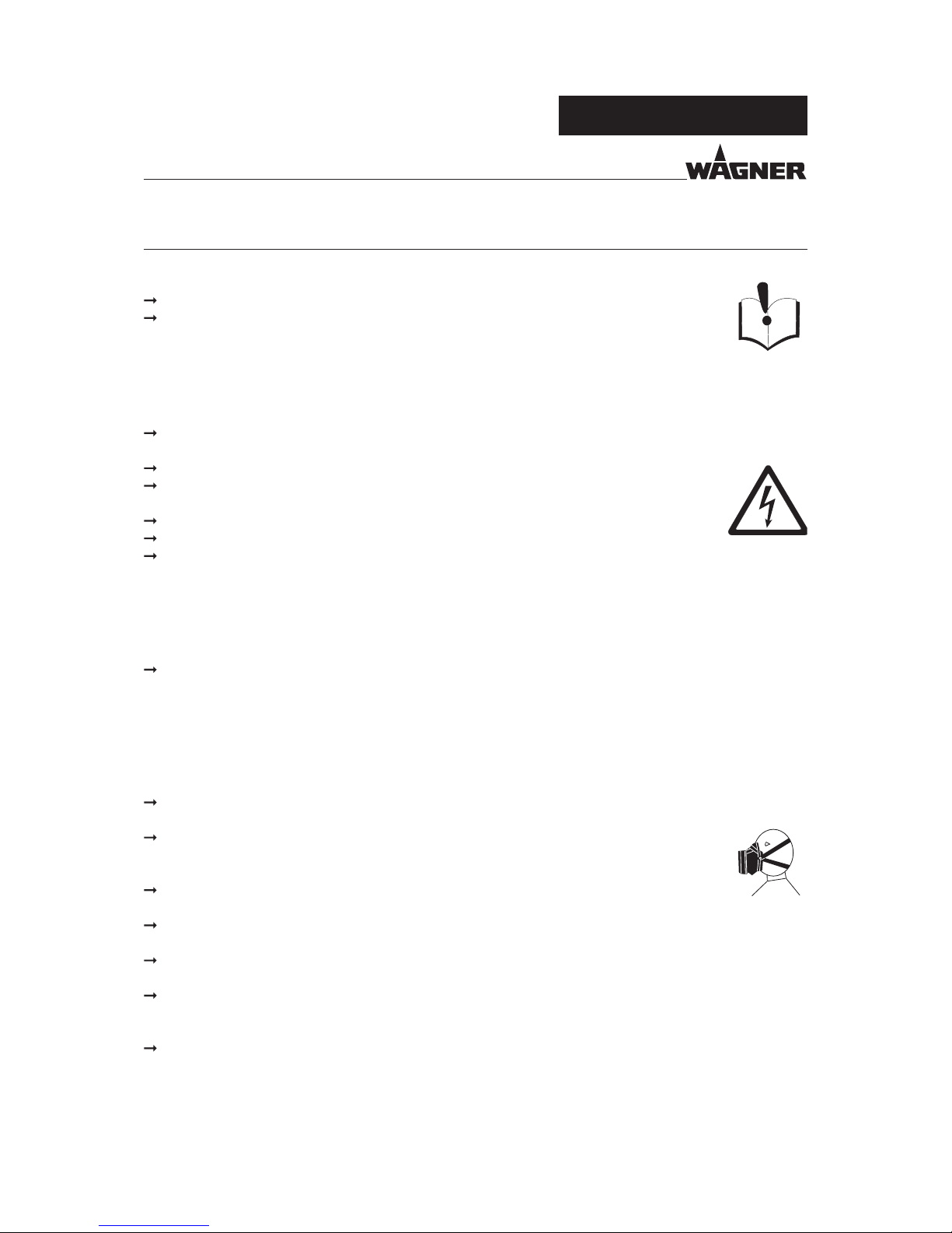
1.2 WARNINGS, NOTICES AND SYMBOLS IN THESE INSTRUCTIONS
Warning instructions in this operating manual highlight particular dangers to users and to
the device and state measures for avoiding the hazard. These warning instructions fall into
the following categories:
Danger - immediate risk of danger.
Non-observance will result in death or serious injury.
Warning - possible imminent danger.
Non-observance may result in death or serious injury.
Caution - a possibly hazardous situation.
Non-observance may result in minor injury.
Notice - a possibly hazardous situation.
Non-observance may result in damage to property.
Note - provides information about particular characteristics and how to proceed.
This notice warns you of a hazard!
Possible consequences of not observing the warning instructions.
The signal word indicates the hazard level.
The measures for preventing the danger and its
consequences.
DANGER
This notice warns you of a hazard!
Possible consequences of not observing the warning instructions.
The signal word indicates the hazard level.
The measures for preventing the danger and its
consequences.
WARNING
This notice warns you of a hazard!
Possible consequences of not observing the warning instructions.
The signal word indicates the hazard level.
The measures for preventing the danger and its
consequences.
CAUTION
This notice warns you of a hazard!
Possible consequences of not observing the warning instructions. The signal word
indicates the hazard level.
The measures for preventing the danger and its consequences.
NOTICE
1.3 LANGUAGES
The operating manual is available in the following languages:
Language: Order No. Language: Order No. Language: Order No.
German 2348756 English 2349369 French 2355489
Italian 2355491 Spanish 2355493 Russian 2356564
Chinese 2356565 Swedish 2356566 Polish 2356567
Norwegian 2356568 Dutch 2356570 Finnish 2356571
Czech 2356572
The service manual is available in the following languages:
Language: Order No. Language: Order No.
German 2355505 English 2355506
Additional languages on request or at:
Page 5
5
GM 1-350/530
OPERATING MANUAL
VERSION 02/2015 ORDER NUMBER DOC2349369
2 CORRECT USE
2.1 SAFETY PARAMETERS
WAGNER accepts no liability for any damage arising from incorrect use.
Use the device only to work with the products recommended by WAGNER.
Only operate the device as a whole.
Do not deactivate safety xtures.
Use only WAGNER original spare parts and accessories.
The device may only be operated under the following conditions:
The operating sta must be trained on the basis of this operating manual.
The safety regulations listed in this operating manual must be observed.
The operating, maintenance and repair information in this operating manual must be observed.
The statutory requirements and accident prevention regulation standards in the country of use must be
observed.
2.2 REASONABLY FORESEEABLE MISUSE
The forms of misuse listed below may result in physical injury or property damage:
coating work pieces which are not grounded;
unauthorized conversions or modi cations to the system;
processing dry or similar coating products, e.g., powder;
using defective components, spare parts or accessories other than those described in
the "Accessories" chapter of this operating manual;
continuing work with a defective or kinked product hose;
working with incorrectly set values;
processing food.
2.3 RESIDUAL RISKS
Residual risks are risks which cannot be ruled out even in the event of correct use.
If necessary, warning and prohibition signs at the relevant points of risk indicate residual risks.
Residual risk Source Consequences Speci c measures Lifecycle phase
Skin contact with
lacquers and
cleaning agents
Handling of
lacquers and
cleaning agents
Skin irritations, Wear protective
clothing,
operation,
allergies observe safety data
sheets
maintenance,
disassembly
Lacquer in air
outside the de ned
working area
Lacquering outside
the de ned
working area
Inhalation of
substances
hazardous to health
Observe work
and operation
instructions
operation,
maintenance
Page 6
6
GM 1-350/530
Serial-No. XXXXX
J. Wagner AG
9450 Altstaetten
SWISS MADE
WARNING
SKIN INJECTION HAZARD
READ INSTRUCTION MANUAL
II 2G X
1
6
5
B_5041
GM 1-530
MAX WPR
530 bar
7687 psi
MAX TEMP
85 °C
185 °F
3
4
2
FIRE AND EXPLOSION HAZARD
READ INSTRUCTION MANUAL
7
8
OPERATING MANUAL
VERSION 02/2015 ORDER NUMBER DOC2349369
3 IDENTIFICATION
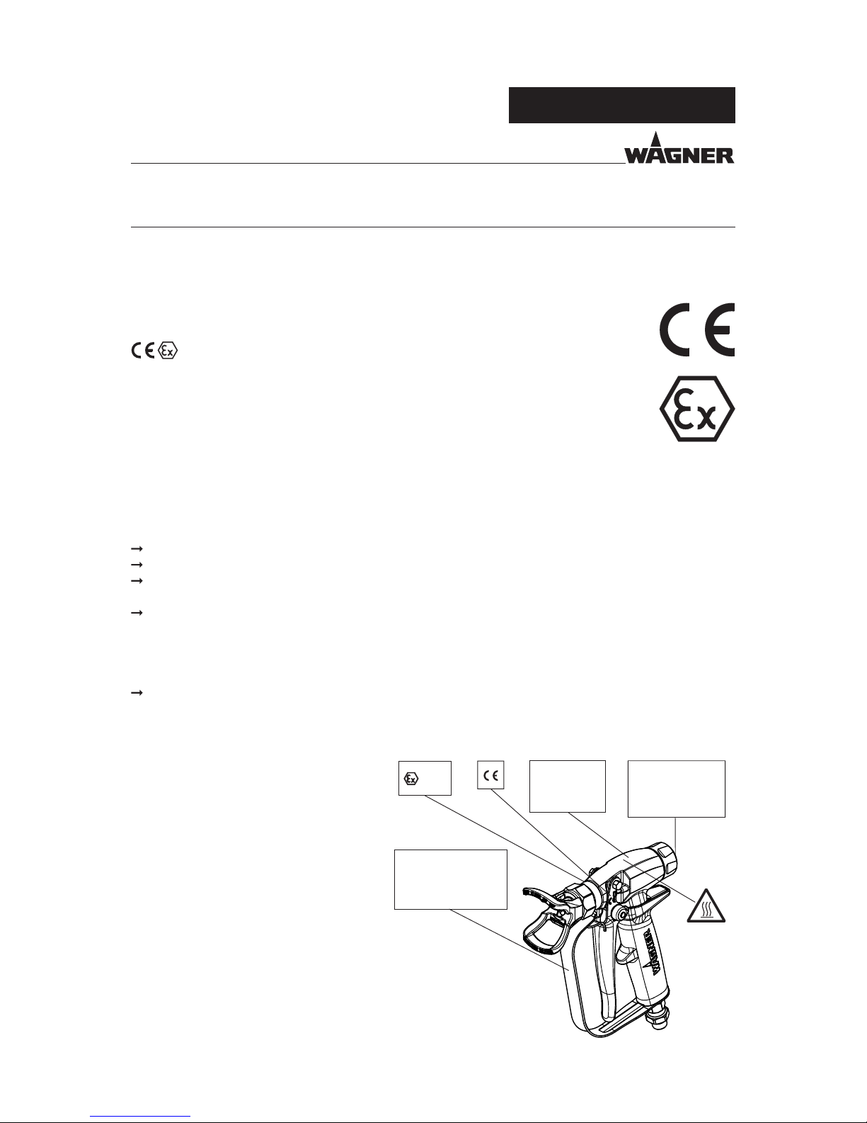
3.1 CE EXPLOSION PROTECTION IDENTIFICATION
The device is compliant with Ex II 2G X regulations and is suitable for use in potentially
explosive areas (zone 1) in accordance with Directive 94/9/EC (ATEX).
Device type: Airless manual gun
Manufacturer: J. Wagner AG, CH - 9450 Altstätten
II 2G X
3.2 IDENTIFICATION "X"
X: The maximum surface temperature corresponds to the permissible product temperature.
This and the permissible ambient temperature can be found in the "Technical Data" chapter.
Safe handling of WAGNER spray devices
Mechanical sparks can form if the device comes into contact with metal.
In an explosive atmosphere:
Do not knock or push the device against steel or rusty iron.
Do not drop the spray gun.
Use only tools that are made of a permitted material.
Ignition temperature of the coating material
Ensure that the ignition temperature of the coating product is above the maximum
surface temperature.
Cleaning
If there are deposits on the surfaces, the device may form electrostatic charges. Flames or
sparks can form during discharge.
Remove deposits from the surfaces to maintain conductivity.
3.3 TYPE PLATE
3.3.1 GM 1530 EXAMPLE TYPE PLATE
1 Serial number
2 Spray gun designation
3 Maximum product pressure
4 Maximum product temperature
5 Warning
6 Danger of injury from injection/read operating manual
7 Fire and explosion hazard/read operating manual
8 "Warning – Hot surface!"
CE European Communities 2 Category 2 (Zone 1)
Ex Symbol for explosion protection G Ex-atmosphere gas
II Device class II X Special Notice
Page 7
7
GM 1-350/530
OPERATING MANUAL
VERSION 02/2015 ORDER NUMBER DOC2349369
4 GENERAL SAFETY INSTRUCTIONS
4.1 SAFETY INSTRUCTIONS FOR THE OPERATOR
4.1.1 ELECTRICAL EQUIPMENT
4.1.2 PERSONNEL QUALIFICATIONS
4.1.3 SAFE WORK ENVIRONMENT
Keep this operating manual at hand near the device at all times.
Always follow local regulations concerning occupational safety and accident
prevention.
Electrical devices and equipment
To be provided in accordance with the local safety requirements with regard to the
operating mode and ambient in uences.
May only be maintained by skilled electricians or under their supervision.
Must be operated in accordance with the safety regulations and electrotechnical
regulations.
Must be repaired immediately in the event of problems.
Must be decommissioned if they pose a hazard.
Must be de-energized before work is commenced on active parts. Inform sta about
planned work. Observe electrical safety regulations.
Ensure that the device is operated and repaired only by trained persons.
Ensure that the oor in the working area is static dissipative in accordance with
EN61340-4-1 (resistance must not exceed 100 megohms).
Ensure that all persons within the working area wear static dissipative shoes. Footwear
must comply with EN 20344. The measured insulation resistance must not exceed
100megohms.
Ensure that during spraying, persons wear static dissipative gloves. The grounding
takes place via the gun's bow guard.
If protective clothing is worn, including gloves, it has to comply with EN 1149-5. The
measured insulation resistance must not exceed 100 megohms.
Paint mist extraction systems/ventilation systems must be tted on site according to
local regulations.
Ensure that the following components of a safe working environment are available:
- Product/air hoses adapted to the working pressure.
- Personal safety equipment (breathing and skin protection).
Ensure that there are no ignition sources such as naked ames, sparks, glowing wires,
or hot surfaces in the vicinity. Do not smoke.
Page 8

8
GM 1-350/530
OPERATING MANUAL
VERSION 02/2015 ORDER NUMBER DOC2349369
4.2.1 SAFE HANDLING OF WAGNER SPRAY DEVICES
The spray jet is under pressure and can cause dangerous injuries.
Avoid injection of paint or ushing agents:
Never point the spray gun at people.
Never reach into the spray jet.
Before all work on the device, in the event of work interruptions and functional faults:
- Switch o the energy/compressed air supply.
- Relieve the pressure from the spray gun and device.
- Secure the spray gun against actuation.
- In the event of functional faults, remedy the fault as described in the "Troubleshooting"
chapter.
If necessary or at least every 12 months, the liquid ejection devices should be checked
for safe working conditions by an expert (e.g., Wagner Service Technician) in accordance
with the guidelines for liquid ejection devices (ZH1/406 and BGR500 Part2 Chapter2.29
and 2.36).
- For shut down devices, the examination can be suspended until the next start-up.
Carry out the work steps as described in the "Pressure Relief" chapter:
- If pressure relief is required.
- If the spraying work is interrupted or stopped.
- Before the device is cleaned on the outside, checked or serviced.
- Before the spray nozzle is installed or cleaned.
In the event of skin injuries caused by paint or ushing agents:
Note the paint or ushing agent that you have been using.
Consult a doctor immediately.
Avoid risk of injury from recoil forces:
Ensure that you have firm footing when operating the spray gun.
Only hold the spray gun brie y in a position.
4.2 SAFETY INSTRUCTIONS FOR STAFF
Always follow the information in this manual, particularly the general safety instructions
and the warning instructions.
Always follow local regulations concerning occupational safety and accident
prevention.
4.2.2 GROUNDING THE DEVICE
In order to avoid electrostatic charging of the device, the device must be grounded.
Friction, owing liquids and air or electrostatic coating processes create charges. Flames
or sparks can form during discharge.
Ensure that the device is grounded for every spraying operation.
Ground the work pieces to be coated.
Ensure that all persons inside the working area are grounded, e.g., that they are
wearing static dissipative shoes.
Wear static dissipative gloves when spraying. The grounding takes place via the gun's
bow guard.
Page 9

9
GM 1-350/530
OPERATING MANUAL
VERSION 02/2015 ORDER NUMBER DOC2349369
4.2.3 PRODUCT HOSES
Ensure that the hose material is chemically resistant to the sprayed products and the
used ushing agents.
Ensure that the product hose is suitable for the pressure generated.
Ensure that the following information can be seen on the high pressure hose:
- Manufacturer
- Permissible operating pressure
- Date of manufacture
Make sure that the hoses are laid only in suitable places. Hoses should not be laid in the
following places under any circumstances:
- In high-traffic areas
- At sharp edges
- On moving parts
- On hot surfaces
Ensure that the hoses are never run over by vehicles (e.g. fork lifts), or that the hoses are
never put under pressure from the outside in any other way.
Ensure that the hoses are never kinked. Observe maximum bending radii.
Make sure that the hoses are never used to pull or move the equipment.
The electrical resistance of the product hose, measured at both valves, must be less
than 1 megohm.
Suction hoses may not be subjected to pressure.
Several liquids have a high expansion coe cient. In some cases their volume can rise with
consequent damage to pipes, ttings, etc. and cause uid leakage.
When the pump sucks liquid from a closed tank, ensure that air or a suitable gas can enter
the tank. Thus a negative pressure is avoided. The vacuum could implode the container
(squeeze) and can cause it to break. The container would leak and the liquid would ow
out. The pressure created by the pump is a multiplication of the inlet air pressure.
4.2.4 CLEANING AND FLUSHING
Relieve the pressure from the device.
De-energize the device electrically.
Preference should be given to non- ammable cleaning and ushing agents.
Observe the speci cations of the paint manufacturer.
Ensure that the ash point of the cleaning agent is at least 15 K above the ambient
temperature or that cleaning is undertaken at a cleaning station with technical
ventilation.
Take measures for workplace safety (see Chapter 4.1.3).
When commissioning or emptying the device, please note that an explosive mixture
may temporarily exist inside the lines and components of equipment:
- depending on the coating product used,
- depending on the ushing agent (solvent) used,
explosive mixture inside the lines and items of equipment.
Page 10
10
GM 1-350/530
OPERATING MANUAL
VERSION 02/2015 ORDER NUMBER DOC2349369
4.2.5 HANDLING HAZARDOUS LIQUIDS, VARNISHES AND PAINTS
When preparing or working with lacquer and when cleaning the device, follow the
working instructions of the manufacturer of the lacquers, solvents and cleaning agents
being used.
Take the speci ed protective measures, in particular wear safety goggles, protective
clothing and gloves, as well as skin protection cream if necessary.
Use a mask or breathing apparatus if necessary.
For su cient health and environmental safety: Operate the device in a spray booth or
on a spraying wall with the ventilation (extraction) switched on.
Wear suitable protective clothing when working with hot products.
Only electrically conductive tanks may be used for cleaning and ushing agents.
The containers must be grounded.
An explosive gas/air mixture forms in closed containers.
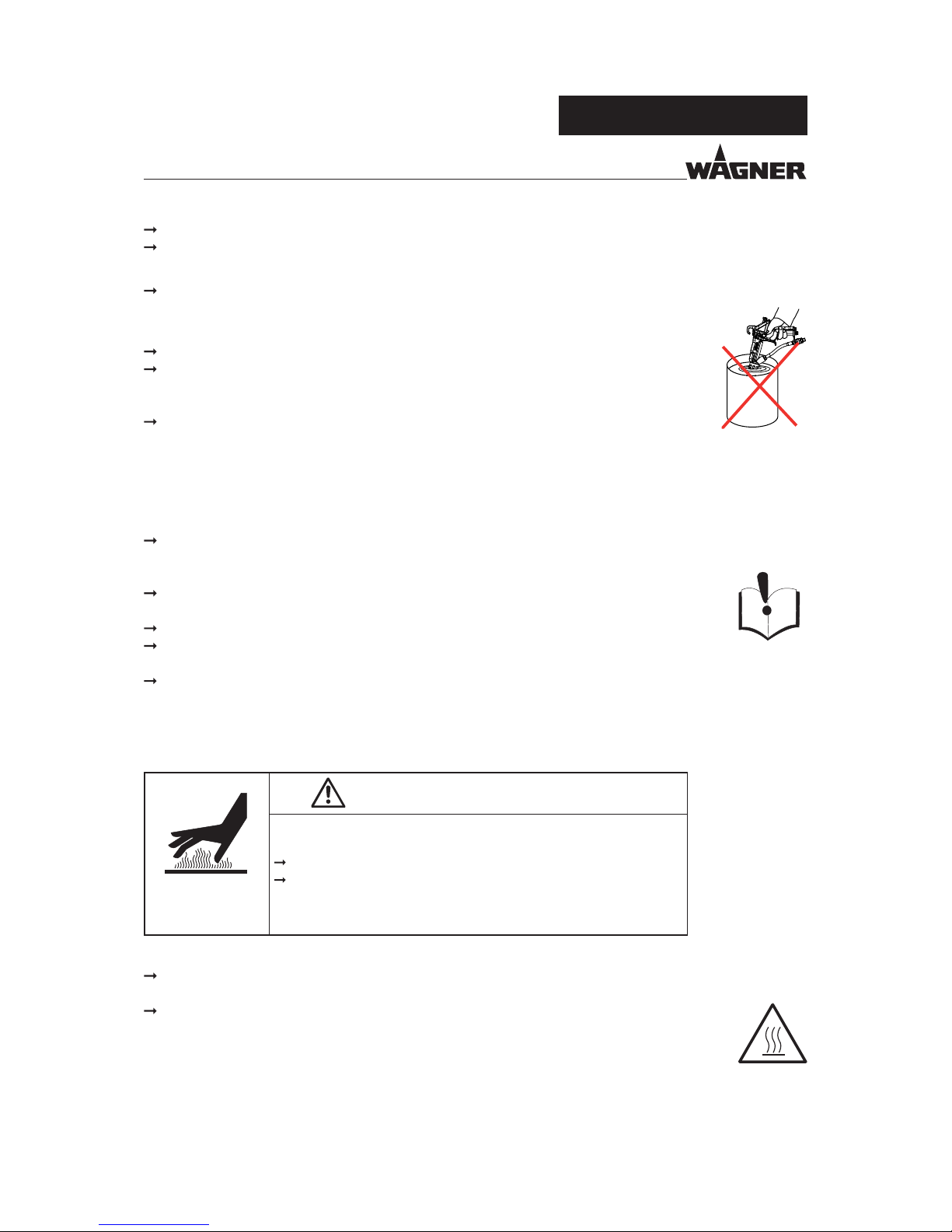
Never spray into a closed tank when using solvents for ushing.
External cleaning
When cleaning the exterior of the device or its parts, also observe the following:
Disconnect the pneumatic supply line.
Use only moistened cloths and brushes. Never use abrasive agents or hard objects, and
never spray cleaning agents with a spray gun. Cleaning the device must not damage it
in any way.
Ensure that no electrical component is cleaned with nor even immersed into solvent.
4.2.6 TOUCHING HOT SURFACES
Only touch hot surfaces (temperature > 43 °C; 109 °F) if you are wearing protective
gloves.
When operating the device with a coating product with a temperature of > 43 °C;
109.4°F:
- Identify the device with a warning label, "Warning – Hot surface".
Order No.
9998910 Instruction label
9998911 Protection label
Note: Order the two stickers together.
WARNING
Hot coating products!
Burns
Wear antistatic protective gloves.
When operating the device with a coating product with a
temperature of > 43 °C;109.4 °F, identify the device with a
warning label that says "Warning - hot surface".
Page 11

11
GM 1-350/530
A
D
B
C
E
F
G
B_5042
A
D
B
C
E
F
G
B
B_5302
E
OPERATING MANUAL
VERSION 02/2015 ORDER NUMBER DOC2349369
5 DESCRIPTION
Designation Designation
A Preload nut E Nozzle holder
B Trigger locking device F Reversible nozzle (not included in scope of delivery)
C Product connection with swivel joint G Gun housing
D Trigger
5.1 DESIGN
5.2 DEVICE TYPE
Airless manual gun for manually coating work pieces.
5.3 TYPE OF USE
The spray gun is intended for atomizing liquid coating products under pressure (airless process).
A high-pressure pump sucks in the coating product and conveys it under pressure to the nozzle in the spray
gun. The coating product atomizes as it is pressed through the nozzle at high pressure. The product valve
opens if the trigger (D) is operated with the locking device (B) released. The spray pro le changes depending
on the nozzle selection.
5.4 MODE OF OPERATION
Secure the spray gun with the locking device (B).
The nozzle holder (E) has an anti-contact guard.
5.5 PROTECTIVE AND MONITORING EQUIPMENT
This Airless manual gun is available in two di erent variants (350 bar, 530 bar). The choice of nozzle depends
on the application, therefore these components are not included in the scope of delivery. A selection guide for
gun accessories can be found in Chapter 12.
5.6 SCOPE OF DELIVERY
Order No.
Designation
Field of application
1 2349286 GM 1-350 35 MPa; 350 bar; 5076 psi, NPSM1/4" product connection, nishing
1 2349287 GM 1-530
53 MPa; 530 bar; 7687 psi, NPSM1/4" product connection, protective coating
Page 12

12
GM 1-350/530
OPERATING MANUAL
VERSION 02/2015 ORDER NUMBER DOC2349369
Metals Plastics
Carbide Stainless steel 1.4305 Aluminum UHMW-PE
Stainless steel 1.4301 Stainless steel 1.4104
5.7.1 MATERIALS OF PAINTWETTED PARTS
5.7 DATA
5.7.2 PROCESSIBLE MATERIALS
Top-coat paints, primer paints, corrosion protection, textured lacquers, lyes, staining solvents, clear lacquers,
separating agents, etc. with a solvent or water base. If you want to spray working materials other than the
aforementioned, please contact a WAGNER representative.
Note:
Please contact your local WAGNER dealer and the lacquer manufacturer if you encounter application problems.
Order No. Designation
1 2355332 CE Declaration of Conformity
1 2348756 Operating manual, German
1 See Chapter 1.3 Operating manual in local language
For special versions the delivery note applies.
The standard equipment for spray guns includes:
Airless manual gun
Description Devices GM 1-350 GM 1-530
Maximum product pressure MPa; bar; psi 35; 350; 5076 53; 530; 7687
Fluid inlet inch NPSM 1/4"
Filter * Mesh 50, 100, 150, 200
Weight g; oz 511 g; 18.0 oz 581 g; 20.5 oz
pH range of the product pH 3.5 – 9.0
Maximum product temperature °C; °F 85; 185
Sound level at 12 MPa; 120 bar;
1,740psi product pressure**
dB(A) 75
Storage conditions °C; °F
-20 – 60 ; -4 – 140
Installation conditions °C; °F 0 – 40; 32 – 132
Relative humidity at the storage or
assembly location
% 10 – 95
Dimensions mm; inch Length: 163; 6.42
Height: 195; 7.68
Width: 39; 1.54
* For lter sizes, see Chapter 13.2
** A-rated sound pressure level of emissions measured at a distance of 0.5 m, Lpa0.5m, in accordance with
DIN EN 14462: 2005.
5.7.3 TECHNICAL DATA
Page 13

13
GM 1-350/530
A
B
C
D
E
G
H
J
I
K
B_05044
F
OPERATING MANUAL
VERSION 02/2015 ORDER NUMBER DOC2349369
6.2.1 TYPICAL AIRLESS SPRAYING SYSTEM
A Material pump
B Pressure air shut-o valve
C Pressure regulator
D Grounding cable
E High-pressure paint hose,
electrically conductive
The Airless manual gun GM 1-350/530 must be combined with various components to
make up a spraying system. The system shown in the gure is only one example of an
Airless spraying system. Your Wagner distributor would be happy to assist you in creating
a spraying system solution that meets your individual needs.
You must familiarize yourself with the operating manuals and the safety regulations for all
additional system components required before starting with commissioning.
6.2 ASSEMBLY AND INSTALLATION
F Airless manual gun
G High-pressure lter/ uid pressure release
H Return line
I Pump mounting trolley
J Suction system
K Compressed air main
6 ASSEMBLY AND COMMISSIONING
6.1 TRAINING ASSEMBLY/COMMISSIONING STAFF
A skilled person must check to ensure that the device is in a reliable state after it is installed
and commissioned.
The assembly and commissioning sta must have the technical skills to safely undertake
commissioning.
When assembling, commissioning and carrying out all work, read and follow the
operating manuals and safety regulations for the additionally required system
components.
Page 14

14
GM 1-350/530
OPERATING MANUAL
VERSION 02/2015 ORDER NUMBER DOC2349369
6.2.2 VENTILATION OF THE SPRAY BOOTH
6.2.3 PRODUCT SUPPLY
NOTICE
Impurities in the spraying system!
Spray gun blockage, materials harden in the spraying system
Flush the spray gun and paint supply with a suitable ushing agent.
6.3 GROUNDING
A conductive connection (potential equalization cable) must be established between
original bundles and the equipment.
Daily: Check the grounding (see Chapter 6.3) and hoses (see Chapter 8.2.3.1).
6.4 SAFETY CHECKS
The viscosity of the lacquer is of great importance. The best spraying results are obtained
with values between 80 and 260 millipascals x sec (mPa∙s).
6.5 PREPARATION OF LACQUER
6.3.1 GROUNDING CHECK
Daily: Before starting work, carry out a visual inspection to ensure that the system is
grounded.
Operate the device in a spray booth approved for the working materials.
-or Operate the device on an appropriate spraying wall with the ventilation (extraction)
switched on.
Observe national and local regulations for the outgoing air speed.
Observe the safety instructions in Chapter 4.1.3.
Observe the safety instructions in Chapter 4.2.2.
Please also read the technical data sheet of the lacquer for optimal processing, viscosity
adjustment and intermixing of the product.
WARNING
Discharge of electrostatically charged components in
atmospheres containing solvents!
Explosion hazard from electrostatic sparks or ames.
Ground all device components.
Ground the work pieces to be coated.
Page 15

15
GM 1-350/530
OPERATING MANUAL
VERSION 02/2015 ORDER NUMBER DOC2349369
1. Secure the spray gun.
2. Connect the product hose to the spray gun and product supply system.
3. For spray guns with lters insert a suitable lter ( lter insert, see Chapter 13.2).
4. Insert the saddle and seal into the nozzle holder. Push in the Pro Tip nozzle. Screw
the entire nozzle holder onto the spray gun. Tighten nozzle holder using an openend wrench (size 30).
5. Visually check the permissible pressures for all the system components.
6. Make sure that the device and all other conductive parts within the work area are
grounded.
7. To perform a leak test on the entire installation, the pressure is slowly increased
using a suitable medium, step by step, until the maximum pressure indicated on the
type plate is reached.
Note:
Set the operating pressure to 100 bar; 10 MPa; 1450 psi.
Pull the trigger and check whether the gun closes cleanly upon release.
8. Relieve the pressure of the spray gun and product pressure generator and secure
the spray gun.
6.6.2 PREPARATION FOR COMMISSIONING
Impurities in the spraying system!
Clogging of the spray gun
Flush the spray gun and paint supply with a suitable ushing agent before
commissioning.
NOTICE
6.6.3 COMMISSIONING
A skilled person must check to ensure that the device is in a reliable state after it is installed
and commissioned.
This includes:
- Carry out a safety check in accordance with Chapter 8.2.3.
6.6.4 VERIFYING A SAFE OPERATIONAL CONDITION
6.6 COMMISSIONING
6.6.1 SAFETY INSTRUCTIONS
Observe safety instructions in Chapter 4.
Page 16

16
GM 1-350/530
OPERATING MANUAL
VERSION 02/2015 ORDER NUMBER DOC2349369
7 OPERATION
7.1 TRAINING THE OPERATING STAFF
7.2 SAFETY INSTRUCTIONS
Observe the safety instructions in Chapters 4.1, 4.1.3, 4.2, and 4.2.1.
7.3 WORK
Ensure that:
the regular safety checks are carried out in accordance with Chapter 8.2.3,
commissioning is carried out in accordance with Chapter 6.6.
The operating sta must be quali ed and t to operate the entire system.
The operating sta must be familiar with the potential risks associated with improper
behavior as well as the necessary protective devices and measures.
Before work commences, the operating sta must receive appropriate system training.
7.3.1 STARTING TO SPRAY WITH THE AIRLESS
WARNING
High pressure spray jet!
Danger to life from injecting paint or solvent
Never reach into the spray jet.
Never point the spray gun at people.
Consult a doctor immediately in the event of skin injuries caused
by paint or solvent. Inform the doctor about the paint or solvent
used.
Never seal defective high pressure parts, instead relieve the
pressure from them and replace them.
Wear the appropriate protective clothing, gloves, eyewear and
respiratory protection.
1. Start up with product supply set to approx. 10 MPa; 100 bar; 1450 psi operating
pressure.
2. Spray (release locking device and pull trigger) and at the same time observe how
the product is atomizing.
3. Set the uid pressure on the material pump to a point where good product
atomization is achieved.
Note:
-
Adjust the nozzle, product pressure and product temperature until you nd the
optimum setting.
- The amount of product can be adjusted by changing the product pressure and
temperature or by inserting another nozzle (see Chapter 7.3.3 and Chapter 12.1).
Page 17

17
GM 1-350/530
OPERATING MANUAL
VERSION 02/2015 ORDER NUMBER DOC2349369
7.3.2 PRESSURE RELIEF / WORK INTERRUPTION
The pressure must always be relieved:
- when the spraying tasks are nished,
- before carrying out maintenance work on the spraying system,
- before carrying out cleaning tasks on the spraying system,
- before moving the spraying system to another location,
- if something must be checked on the spraying system,
- if the nozzle or the lter is removed from the spray gun.
The components for pressure relief on a CE-compliant spray system include:
- Air cock with pressure relief hole mounted between compressed air source and
pneumatic pump.
- Product pressure relief valve mounted between pump and spray gun.
Please read the general safety instructions in Chapter 4.
Pressure relief procedure:
1. Secure the spray gun with the locking device.
2. Close air supply to pump and relieve air pressure in air motor.
3. Release the locking device on the spray gun.
4. Press the electrically conductive part of the spray gun against grounded metal tank
for return product and open the spray gun using the trigger guard; keep it open
until no further overpressure is detected.
5. Secure the spray gun with the locking device.
6. Open product pressure relief valve (see system description) and leave open.
If the pressure is still not completely relieved after this:
- If nozzle is clogged: slowly and carefully loosen the union nut to release the
remaining pressure.
- If product hose is obstructed: slowly loosen the hose connections to release the
remaining pressure.
Note:
Always follow the procedure described above if pressure relief is speci ed in the
instructions.
Page 18

18
GM 1-350/530
B_5049
OPERATING MANUAL
VERSION 02/2015 ORDER NUMBER DOC2349369
7.3.3 CHANGING THE AIRLESS NOZZLE
Defective Airless nozzle!
Insu cient paint application quality
Do not use sharp-edged objects on the carbide on the Airless nozzle.
Nozzles can be easily removed and replaced without
having to take apart the Airless spray gun.
1. Relieve the pressure on the spray gun and product
pressure generator in accordance with Chapter 7.3.2.
2. Secure the spray gun with the locking device.
3. Remove the nozzle from the opening at the nozzle
holder. Attention: when removing the reversing nozzle,
always aim the spray gun at the oor, as product can still
come out due to product being trapped between the
reversing nozzle and the valve seat.
4. Insert the new nozzle into the opening at the nozzle
holder. The tip on the reversing nozzle has to point
forward in the direction of spray.
NOTICE
For disassembly and assembly of Airless nozzles, see Chapter 7.3.3.
The Airless nozzle can be placed into a cleaning solution recommended by the paint
manufacturer.
7.3.4 CLEANING THE AIRLESS NOZZLE
Page 19

19
GM 1-350/530
B_5054
B_5303
OPERATING MANUAL
VERSION 02/2015 ORDER NUMBER DOC2349369
7.3.5 ELIMINATE NOZZLE CLOGGING
1.
Relieve the pressure on the spray gun and product pressure generator in accordance with Chapter 7.3.2.
2. Secure the spray gun with the locking device.
3. Rotate the reversing nozzle 180° so that its tip is pointing opposite the direction of spray.
Attention: when rotating the reversing nozzle, always aim the spray gun at the oor, as product can still
come out due to product being trapped between the reversing nozzle and the valve seat.
4. Brie y trigger the spray gun so that the pressure eliminates the clog.
Note:
Only activate the trigger brie y if the nozzle is installed in the reversed direction.
7.3.6 HORIZONTAL/VERTICAL SPRAYING
1. Secure the spray gun with the locking device.
2. Turn the nozzle holder to the desired position.
Attention: always turn the nozzle holder clockwise (see illustration) so that the threaded connection
cannot become loose. After turning, check whether the nozzle holder is tight. If not, tighten.
Horizontal sprayingVertical spraying
Page 20

20
GM 1-350/530
OPERATING MANUAL
VERSION 02/2015 ORDER NUMBER DOC2349369
8 CLEANING AND MAINTENANCE
Cleaning work should be undertaken regularly and carefully by quali ed and trained sta .
They should be informed of speci c hazards during their training.
The following hazards may arise during cleaning work:
Health hazard from inhaling solvent vapors
Use of unsuitable cleaning tools and aids
8.1 CLEANING
8.1.2 SAFETY INSTRUCTIONS
8.1.1 CLEANING STAFF
DANGER
Exploding gas / air mixture!
Danger to life from ying parts and burns
Never spray into a closed tank.
Ground the tank.
WARNING
Explosive atmosphere!
Explosive gases are produced when aluminum comes into contact
with halogenated hydrocarbons
To clean aluminum, do not use liquids containing halogenated
hydrocarbons.
WARNING
Discharge of electrostatically charged components in
atmospheres containing solvents!
Explosion hazard from electrostatic sparks or ames.
Ground all device components.
Ground the work pieces to be coated.
Page 21

21
GM 1-350/530
B_5045
OPERATING MANUAL
VERSION 02/2015 ORDER NUMBER DOC2349369
8.1.3 FLUSHING AND CLEANING THE SPRAY GUN
Observe safety instructions in Chapter 4.
The spray gun and the device must be cleaned and ushed daily. The cleaning/ ushing
agents used for cleaning or ushing must correspond with the working material.
Product
Locking device in secured
position
Note:
Methylene chloride is not recommended as an agent for ushing or cleaning the spray
gun or other system components.
1. Relieve the pressure on the spray gun and product pressure generator in
accordance with Chapter 7.3.2.
2. Secure the spray gun with the locking device.
3. Connect the solvent supply.
4. Disassemble the Airless nozzle and clean it separately (see Chapter 7.3.3 and 7.3.4).
5. Raise the pressure of the rinsing agent supply to a maximum of 4 MPa; 40 bar;
580psi, unlock the spray gun and thoroughly rinse it.
6. Relieve the pressure on the spray gun and product pressure generator.
7. Secure the spray gun with the locking device.
8. Clean the spray gun body with a cleaning agent recommended by the lacquer
manufacturer and dry with a cloth or blow gun.
Page 22

22
GM 1-350/530
OPERATING MANUAL
VERSION 02/2015 ORDER NUMBER DOC2349369
8.2 MAINTENANCE
8.2.1 MAINTENANCE STAFF
Maintenance work should be undertaken regularly and carefully by quali ed and trained
sta . They should be informed of speci c hazards during their training.
The following hazards may arise during maintenance work:
- Health hazard from inhaling solvent vapors
- Use of unsuitable tools and aids
An authorized person must ensure that the device is checked for being in a reliable state
after maintenance work is completed.
8.2.2 SAFETY INSTRUCTIONS
Observe the safety instructions in Chapter 4 and Chapter 8.1.2.
Prior to maintenance
- Flush and clean the system. Chapter 8.1.3.
After maintenance
- Carry out a safety check in accordance with Chapter 8.2.3.
- Put the system into operation and check for leaks as described in Chapter 6.6.
In accordance with the guideline for liquid ejection devices (ZH1/406 and BGR 500
Part2 Chapter 2.29 and Chapter 2.36):
- The liquid ejection devices should be checked by an expert (e.g. Wagner service
technician) for their safe working conditions as required and at least every
12months.
- For shut down devices, the examination can be suspended until the next start-up.
DANGER
Incorrect maintenance/repair!
Danger to life and equipment damage.
Only a WAGNER service center or a suitably trained person may
carry out repairs and replace parts.
Only repair and replace parts that are listed in the Chapter
"Spare parts" and that are assigned to the unit.
Before all work on the device and in the event of work
interruptions:
- Switch o the energy and compressed air supply.
- Relieve the pressure from the spray gun and device.
- Secure the spray gun against actuation.
Observe the operating manual and service manuals at all times
when carrying out work.
Page 23

23
GM 1-350/530
OPERATING MANUAL
VERSION 02/2015 ORDER NUMBER DOC2349369
The service life of the complete hoses between product pressure generator and application
device is reduced due to environmental in uences even when handled correctly.
Check hoses, pipes, and couplings every day and replace if necessary.
Before every commissioning, check all connections for leaks.
Additionally, the operator must regularly check the complete hoses for wear and tear
as well as for damage at intervals that he/she has set. Records of these checks must
be kept.
The complete hose is to be replaced as soon as one of the two following intervals has
been exceeded:
- 6 years from the date of the hose crimping (see tting embossing).
- 10 years from the date of the hose imprinting.
Fitting
embossing
Meaning
xxx bar Pressure
yymm
Crimping date
(year/month)
XX Internal code
Hose imprinting Meaning
Wagner
Name /
Manufacturer
yymm
Date of
manufacture (year/
month)
xxx bar (xx MPa)
Pressure
e.g. 270 bar (27MPa)
XX Internal code
DNxx (e.g. DN10) Nominal diameter
8.2.3.1 PRODUCT HOSES, TUBES AND COUPLINGS
Bursting hose, bursting threaded joints!
Danger to life from injection of product and from ying parts.
Ensure that the hose material is chemically resistant to the
sprayed products and the used ushing agents.
Ensure that the spray gun, threaded joints, and product hose
between the device and the spray gun are suitable for the
generated pressure.
Ensure that the following information can be seen on the hose:
- Manufacturer
- Permissible operating pressure
- Date of manufacture.
DANGER
8.2.3 SAFETY CHECKS
Daily: Check the grounding (see Chapter 6.3) and hoses (see Chapter 8.2.3.1).
Page 24

24
GM 1-350/530
B_5048
B
A
B_5051
A
B
D
C
OPERATING MANUAL
VERSION 02/2015 ORDER NUMBER DOC2349369
1. Flush and clean the spray gun as described in
Chapter8.1.3.
2. Relieve the pressure on the spray gun and product
pressure generator in accordance with Chapter 7.3.2.
3. Secure the spray gun with the locking device.
Product hose
4. Place the size B open-end wrench on the lower wrench
size across ats of the product connection and hold it in
place.
5. Unscrew the product hose nut using the size A openend wrench.
Assembly:
1. Fit product hose by hand and tighten with 2 openended wrenches.
Description Wrench A Wrench B
wrench size wrench size
GM 1 350 / 530 with lter NPS1/4"
17 mm 19 mm
0.67 inch 0.75 inch
8.3 REPLACING THE PRODUCT HOSE
8.4 REPLACING THE NOZZLE SEAL
1. Flush and clean the spray gun as described in
Chapter 8.1.3.
2. Relieve the pressure on the spray gun and
product pressure generator in accordance with
Chapter 7.3.2.
3. Secure the spray gun with the locking device.
4. Remove reversing nozzle (A).
5. Unscrew nozzle holder (B).
6. Carefully release saddle (C) and nozzle sealing (D)
using a screwdriver.
7. Insert a new nozzle seal (D) and saddle (C) into
the nozzle holder noting the installation position
(see illustration).
8. Screw the nozzle holder onto the spray gun and
push the reversing nozzle (A) into the opening.
Note:
The tip of the reversing nozzle must point forward in
the direction of spray.
Page 25

25
GM 1-350/530
B_5047
A
B
C
D
C
F
E
OPERATING MANUAL
VERSION 02/2015 ORDER NUMBER DOC2349369
1. Flush and clean the spray gun as described in Chapter 8.1.3.
2. Relieve the pressure on the spray gun and product pressure generator in accordance
with Chapter 7.3.2.
3. Secure the spray gun with the locking device.
4. Use the guard bracket (B) with integrated hex tool to loosen and unscrew the lter
housing (A).
5. Remove the lter insert (C) from the lter housing (A).
6. Thoroughly clean the lter housing and gun handle with cleaning agent.
Assembly:
7. Insert a new lter insert (C) with opening downwards into the lter housing (A).
Check the seal (F) to make sure it is in good condition and positioned correctly.
Notice: if the seal (F) becomes damaged, it must also be replaced (order no. 364340).
8. Use the guard bracket to screw in and tighten the lter housing (A).
Note: If the lter insert (C) gets stuck in the lter socket (E), pull o the gun handle (D)
and carefully remove the lter insert (C).
8.5 CHANGING OR CLEANING FILTER INSERT
Disassembly
Installation
position
seal (F)
Page 26

26
GM 1-350/530
OPERATING MANUAL
VERSION 02/2015 ORDER NUMBER DOC2349369
Functional fault Cause Remedy See Chapter
Insu cient product
output.
Nozzle too small. Select larger nozzle. 12
Product pressure too low. Increase product pressure.
Spray gun lter or high-pressure
lter clogged at pump.
Clean or replace lter. 8.4
Nozzle is clogged. Nozzle cleaning. 7.3.4/7.3.5
The valve rod path is too short. Replace the valve rod. See service
manual
Poor spray pattern Nozzle worn. Replace nozzle. 7.3.3
Product pressure too low. Increase the product pressure at
pump.
The product viscosity is too
high.
Dilute the spray product
in accordance with the
manufacturer's instructions.
The nozzle is partially clogged.
Nozzle cleaning. 7.3.4 / 7.3.5
Valve rod leaks The seals on the valve rod are
damaged or the valve rod itself
is damaged.
Completely replace valve rod. See service
manual
Gun will not shut o
correctly
The valve seat or the valve ball
is damaged.
Completely replace valve rod. See service
manual
9 TROUBLESHOOTING AND RECTIFICATION
10 REPAIR WORK
10.1 REPAIR STAFF
Repair work must be carried out carefully by quali ed and trained sta . They should be
informed of speci c hazards during their training. The repairs must be carried out in
accordance with the corresponding service manual.
The following hazards may arise during repair work:
- Health hazard from inhaling solvent vapors
- Use of unsuitable tools and aids
A skilled person must ensure that the device is checked for being in a reliable state after
repair work is completed.
11 DISPOSAL
When the equipment must be scrapped, please di erentiate the disposal of the waste
materials.
The following materials have been used:
Stainless steel Aluminum Plastics Carbide
Consumable products (lacquers, adhesives, ushing and cleaning agents) must be
disposed of in accordance with all applicable legal requirements.
Page 27

27
GM 1-350/530
10° 20° 30° 40° 50° 60°
inch (mm) l/min (gal/min)
07 407
200
0,007 (0,18) 0,23 (0,061)
09 209 309 409 509 609 0,009 (0,23) 0,26 (0,069)
11 111 211 311 411 511 611
50
0,011 (0,28) 0,38 (0,100)
13 113 213 313 413 513 613 813
150
0,013 (0,33) 0,55 (0,145)
15 115 215 315 415 515 615 815 0,015 (0,38) 0,75 (0,198)
17 217 317 417 517 617 0,017 (0,43) 0,96 (0,254)
19 219 319 419 519 619 819
100
0,019 (0,48) 1,20 (0,317)
21 221 421 521 621 821 0,021 (0,53) 1,45 (0,383)
23 423 623 823 0,023 (0,58) 1,62 (0,428)
51
(2,0)
104
(4,0)
152
(6,0)
203
(8,0)
254
(10,0)
305
(12,0)
356
(14,0)
B_05058
80°70°
25 425 525 625
27 427 527 627 827
29
523
629
825
31 431 531 631
33 433
552
35 435 535 635
43
223
543
52
406
(16,0)
223
223
223
223
223
715
717
719
723
0,025 (0,64) 1,92 (0,507)
0,027 (0,69) 2,25 (0,594)
0,029 (0,75) 2,57 (0,679)
0,031 (0,79) 2,95 (0,779)
0,033 (0,83) 3,35 (0,885)
0,035 (0,90) 3,80 (1,004)
0,043 (1,10) 5,89 (1,556)
0,052 (1,30) 6,14 (1,622)
B_05300
OPERATING MANUAL
VERSION 02/2015 ORDER NUMBER DOC2349369
12 ACCESSORIES
12.1 NOZZLES
Wagner Pro Tip HP nozzle chart
Article No. 1006xxx
In order to determine the article number of a nozzle, please
select the number from the table and replace the three xxx.
Example: This means nozzle 411 has article number: 1006411
Size Spray angle
***
***
Material lter
(in mesh)
Drilled hole
Material ow*
Spray pattern width (inch)**
* Speci cation in l/min, tested with water and 100 bar pressure
** Spray width at approx. 30 cm distance from the sprayed object
and 110 bar (11 MPa) of pressure with lacquer 56 DIN/4 seconds
*** Possible deviations in the spray jet width
13 SPARE PARTS
13.1 HOW CAN SPARE PARTS BE ORDERED?
Order No. Designation
2353547 Intermediate piece "F" 11/16-16-UN
12.2 INTERMEDIATE PIECE
Always supply the following information to ensure delivery of the right spare part:
Order number, designation and quantity
The unit quantity does not have to be identical with the numbers in the " " columns of the lists.
This number merely indicates how many of the respective parts are used in each component.
The following information is also required to ensure smooth processing of your order:
- Address for the invoice - Address for delivery
- Name of the person to be contacted in the
event of any queries
- Type of delivery (normal mail, express delivery, air
freight, courier, etc.)
Page 28

28
GM 1-350/530
OPERATING MANUAL
VERSION 02/2015 ORDER NUMBER DOC2349369
DANGER
Incorrect maintenance/repair!
Danger to life and equipment damage.
Only a WAGNER service center or a suitably trained person may
carry out repairs and replace parts.
Only repair and replace parts that are listed in the Chapter
"Spare parts" and that are assigned to the unit.
Before all work on the device and in the event of work
interruptions:
- Switch o the energy and compressed air supply.
- Relieve the pressure from the spray gun and device.
- Secure the spray gun against actuation.
Observe the operating manual and service manuals at all times
when carrying out work.
13.2 SPARE PARTS LIST GM 1350/530
Spare parts list GM 1
35 MPa
Order No.
53 MPa
Order No.
Designation
1 1 2347536 2346856 GM1
2 1 2346614 2346614 Handle
3 1 2353559 2353559 Filter housing with guard bracket
4 1 - 2353599 Trigger guard 4F, complete
4 1 2353600 - Trigger guard 2F, complete
5 1 347335 347335 Pressure spring
6 1 - 2353606 Preload nut, 530bar
6 1 2353607 - Preload nut, 350bar
7 1 2353556 2353556 Valve rod unit
8 1 2353546 2353546 Intermediate piece "G" 7/8-14-UNF
9 2 9910403 9910403 Cap nut
10 1 2343085 2343085 Bolt
11 1 2353611 2353611 Filter socket with seal
12 1 2353613 2353613 Spray gun body
13 2 43411 43411 Actuating pins
14
1 364340 364340 Seal, lter
15 1 - - Filter insert, yellow (middle), 100 mesh per inch *
1 2315723 2315723 * Filter insert, red ( ne), 200 mesh per inch – 10 pieces
1 2315724 2315724 * Filter insert, blue (middle), 150 mesh per inch – 10 pieces
1 2315725 2315725 * Filter insert, yellow (middle), 100 mesh per inch – 10 pieces
1 2315726 2315726 * Filter insert, white (coarse), 50 mesh per inch – 10 pieces
Identi cation in spare parts lists.
Explanation of column "K" (labeling) in the following spare parts lists:
Wearing parts
Note: These parts are not covered by warranty terms.
Not part of standard equipment, available, however, as additional extra.
Page 29

29
GM 1-350/530
1
2
3
14
15
11
4
4
13
12
8
16
17
9
18
10
9
19
16 Nm ;
11.8 lbft
70 Nm;
51.6 lbft
6
5
7
6
3 Nm;
2.2 lbft
B_5304
OPERATING MANUAL
VERSION 02/2015 ORDER NUMBER DOC2349369
16 1 2353548 2353548 Seal kit PT-HD GM1 – 5 pieces
17 1 2353549 2353549 Nozzle holder PT-HD GM1
18 1 9992590 9992590 Loctite 222
19 1 9992804 9992804 Loctite 648
20 1 2353551 2353551 Service set GM1
Wearing parts
= Included in service set
Not part of the standard equipment, but available as a special accessory
Page 30

30
GM 1-350/530
OPERATING MANUAL
VERSION 02/2015 ORDER NUMBER DOC2349369
14.1 IMPORTANT NOTES REGARDING PRODUCT LIABILITY
14.2 WARRANTY CLAIM
14 WARRANTY AND CONFORMITY DECLARATIONS
As a result of an EC regulation e ective from January 1, 1990, the manufacturer shall only
be liable for his product if all parts originate from him or are approved by him, and if the
devices are properly mounted, operated and maintained.
The manufacturer will not be held liable or will only be held partially liable if third-party
accessories or spare parts have been used.
With genuine WAGNER accessories and spare parts, you have the guarantee that all safety
regulations are complied with.
Full warranty is provided for this device:
We will at our discretion repair or replace free of charge all parts which within 24 months
in single-shift, 12 months in 2-shift or 6 months in 3-shift operation from date of receipt by
the purchaser are found to be wholly or substantially unusable due to causes prior to the
sale, in particular faulty design, defective materials or poor workmanship.
The type of warranty provided is such that the device or individual components of the
device are either replaced or repaired as we see t. The resulting costs, in particular
shipping charges, road tolls, labour and material costs will be borne by us except where
these costs are increased due to the subsequent shipment of the device to a location other
than the address of the purchaser.
We do not provide warranty for damage that has been caused or contributed to for the
following reasons:
Unsuitable or improper use, faulty assembly or commissioning by the purchaser or a
third party, normal wear, negligent handling, defective maintenance, unsuitable coating
products, substitute products and the in uence of chemical, electrochemical or electrical
agents, except when the damage is attributable to us.
Abrasive coating products such as red lead, emulsions, glazes, liquid abrasives, zinc
dust paints and so forth reduce the service life of valves, packaging, spray guns, nozzles,
cylinders, pistons etc. Wear and tear due to such causes are not covered by this warranty.
Components that have not been manufactured by WAGNER are subject to the original
warranty of the manufacturer.
Replacement of a component does not extend the period of warranty of the device.
The device should be inspected immediately upon receipt. To avoid losing the warranty,
we or the supplier company are to be informed in writing about obvious faults within
14days upon receipt of the device.
We reserve the right to have the warranty compliance met by a contracting company.
The services provided by this warranty are dependent on evidence being provided in the
form of an invoice or delivery note. If the examination discovers that no warranty claim
exists, the costs of repairs are charged to the purchaser.
It is clearly stipulated that this warranty claim does not represent any constraint on statutory
regulations or regulations agreed to contractually in our general terms and conditions.
J. Wagner AG
Page 31

31
GM 1-350/530
OPERATING MANUAL
VERSION 02/2015 ORDER NUMBER DOC2349369
14.3 CE DECLARATION OF CONFORMITY
Herewith we declare that the supplied version of
GM 1-350
GM 1-530
comply with the following guidelines:
2006/42/EC
94/9/EC
Applied standards, in particular:
DIN EN ISO 12100: 2010 DIN EN ISO 14462: 2005 + A1: 2009
DIN EN 1127-1: 2011 DIN EN 13463-1: 2009
DIN EN 1953: 2013 DIN EN 13463-5: 2011
DIN EN ISO 9001: 2009 DIN EN ISO 13732-1: 2008
DIN EN ISO/IEC 80079-34: 2012 DIN EN ISO 4413: 2010
Applied national technical standards and speci cations, in particular:
EC Certi cate of Conformity
The CE certi cate of conformity is enclosed with this product. If needed, further copies
can be ordered through your WAGNER dealer by specifying the product name and serial
number.
Order number: 2355332
Part 2, Chapter 2.36
Part 2, Chapter 2.29
Note: All titles can be ordered from Heymanns Publishing House in Cologne, or they
can be found on the Internet.
14.4 NOTES ON NATIONAL REGULATIONS AND GUIDELINES
Part 2, Chapter 2.36 "Working with Liquid Ejection Devices"
Part 2, Chapter 2.29 "Working with Coating Products"
Guidelines for equipment cleaning work pieces
with solvents
Avoiding ignition risks
Painting rooms and equipment
Guidelines for liquid ejection devices
Note: All titles can be ordered from Heymanns Publishing House in Cologne, or they
can be found on the Internet.
Page 32

C
E
R
T
I
F
I
E
D
Order No. 2349369
Edition 02/2015
Germany
Phone
Telefax
E-mail
Switzerland
Phone
Telefax
More contact addresses on the internet at:
Company/Locations/WAGNER worldwide
Subject to changes without notice
Document No. 11165362
Version -
 Loading...