

Page 1

Translation of the Original
Operating Manual
GA 5000EACIC
GA 5000EACEC
Version 09/2016
Electrostatic Air Spray Gun
for automatic operation
for at or round jet nozzles
B_05738
II 2 G 0.24mJ X
Page 2

Page 3

VERSION 09/2016 ORDER NUMBER DOC2360922
GA 5000EAC
OPERATING MANUAL
Contents
1 ABOUT THESE INSTRUCTIONS 7
1.1 Preface 7
1.2 Warnings, Notices and Symbols in these Instructions 7
1.3 Languages 8
1.4 Abbreviations 8
1.5 Terminology for the Purpose of this Manual 9
2 CORRECT USE 10
2.1 Device Type 10
2.2 Type of Use 10
2.3 Use in an Explosion Hazard Area 10
2.4 Safety Parameters 10
2.5 Processible Working Materials 11
2.6 Reasonably Foreseeable Misuse 12
2.7 Residual Risks 12
3 IDENTIFICATION 13
3.1 CE Explosion Protection Identi cation 13
3.2 Special Notice "X" 13
3.3 Identi cation "X" (Type Examination Certi cate) 14
3.4 Type Plate 15
4 GENERAL SAFETY INSTRUCTIONS 16
4.1 Safety Instructions for the Operator 16
4.1.1 Electrical Equipment 16
4.1.2 Personnel Quali cations 16
4.1.3 Safe Work Environment 16
4.2 Safety Instructions for Sta 17
4.2.1 Safe Handling of WAGNER Spray Devices 17
4.2.2 Grounding the Device 18
4.2.3 Product Hoses 18
4.2.4 Cleaning and Flushing 19
4.2.5 Handling Hazardous Liquids, Varnishes and Paints 20
4.2.6 Touching Hot Surfaces 20
4.3 Protective and Monitoring Equipment 20
4.4 Use in Areas Subject to Explosion Hazards 21
4.4.1 Safety Regulations 21
4.5 Setting up Stationary Electrostatic Systems 21
4.6 Safety-Relevant Information about Discharges 22
5 DESCRIPTION 23
5.1 Structure (Standard Variant) 23
5.1.1 GA 5000EACIC Design 23
5.1.2 GA 5000EACEC Design 24
5.2 Mode of Operation 25
5.2.1 GA 5000EACIC Mode of Operation 25
5.2.2 GA 5000EACEC Mode of Operation 26
5.3 Protective and Monitoring Equipment 27
5.4 Scope of Delivery 27
3
Page 4

VERSION 09/2016 ORDER NUMBER DOC2360922
GA 5000EAC
OPERATING MANUAL
Table of Contents
5.5 Technical Data 28
5.5.1 GA 5000EAC Dimensions 29
5.6 The WAGNER Electrostatic AirCoat Spraying System 30
5.6.1 Spraying Procedure for AirCoat Round Jet 31
5.6.2 Spraying Procedure for AirCoat Flat Jet 31
5.6.3 Electrostatic E ect 32
6 ASSEMBLY AND COMMISSIONING 33
6.1 Training Assembly/Commissioning Sta 33
6.2 Storage Conditions 33
6.3 Installation Conditions 33
6.4 Assembly and Installation 34
6.4.1 Typical Electrostatic Spraying System 34
6.4.2 Connecting GA 5000EACIC 36
6.4.3 Connecting GA 5000EACEC 37
6.4.4 Ventilation of the Spray Booth 38
6.4.5 Air Supply 39
6.4.6 Product Supply 39
6.4.7 Grounding 40
6.5 Preparation of Lacquer 42
6.5.1 Viscosity Conversion Table 42
6.6 Commissioning 43
6.6.1 Safety Instructions 43
6.6.2 Preparation for Commissioning 43
6.6.3 Commissioning 43
6.7 Verifying a Safe Operational Condition 44
7 OPERATION 45
7.1 Training the Operating Sta 45
7.2 Safety Instructions 45
7.2.1 Emergency Deactivation 46
7.2.2 General Rules for Making Adjustments to the Spray Gun 46
7.3 Working 47
7.3.1 Setting the Spray Pattern Using the Air Pressure Regulator 47
7.3.2 Spraying 48
7.3.3 Pressure Relief/Work Interruption 49
7.3.4 Dismantling the Gun Cover 50
7.3.5 Flushing Out Clogged Round Jet Nozzles 51
7.3.6 Replacing Round Jet Nozzle's Nozzle Insert 51
7.3.7 Changing from AirCoat Round Jet to AirCoat Flat Jet 52
7.3.8 Replacing the AirCoat Flat Jet Nozzles 54
7.3.9 Cleaning of the Nozzle Parts 55
7.3.10 Eliminate Nozzle Clogging 56
7.3.11 Changing the Valve Housing 58
4
Page 5

VERSION 09/2016 ORDER NUMBER DOC2360922
GA 5000EAC
OPERATING MANUAL
Table of Contents
8 CLEANING AND MAINTENANCE 59
8.1 Cleaning 59
8.1.1 Cleaning Sta 59
8.1.2 Safety Instructions 59
8.1.3 Cleaning and Flushing the Device 61
8.2 Maintenance 63
8.2.1 Maintenance Sta 63
8.2.2 Safety Instructions 63
8.2.3 Safety Checks 64
8.2.4 Product Hoses, Tubes and Couplings 65
9 TROUBLE SHOOTING AND RECTIFICATION 66
10 REPAIR WORK 67
10.1 Repair Sta 67
10.2 Safety Instructions 67
10.3 Spray Gun 68
10.3.1 Tools 68
10.3.2 Dismantling of the Spray Gun 69
10.3.3 Cleaning the Parts After Disassembly 74
10.3.4 Assembling the Spray Gun 75
11 FUNCTION TEST AFTER THE REPAIR 82
11.1 Checking the High Voltage 82
11.2 Air Test 84
11.3 Product Pressure Test 84
11.4 Test of Spray Pattern 84
12 DISPOSAL 85
13 ACCESSORIES 86
13.1 Round Jet Nozzles 86
13.1.1 ACR 5000 Round Jet Nozzle Attachment 86
13.1.2 AirCoat Round Jet Nozzle Inserts 86
13.2 Flat Jet Nozzles 86
13.2.1 ACF 5000 Air Caps (Flat Jet) 86
13.2.2 ACF5000 AirCoat Flat Jet Nozzles 87
13.3 Filter 89
13.4 Electric Cables and Hoses 89
13.4.1 Gun Cable 89
13.4.2 Extension Cable for Gun Cable 89
13.4.3 Product Hoses, Standard 90
13.4.4 Product Hoses, LowR 90
13.4.5 Product Hose, 1.5 mm 90
13.4.6 Air Hoses 91
13.5 Miscellaneous 92
5
Page 6

VERSION 09/2016 ORDER NUMBER DOC2360922
OPERATING MANUAL
GA 5000EAC
Table of Contents
14 SPARE PARTS 94
14.1 How Can Spare Parts Be Ordered? 94
14.2 GA 5000EACIC Spray Gun 95
14.2.1 GA 5000EAC – Adapter 98
14.3 GA 5000EACEC Spray Gun 100
14.4 Accessories Spare Parts Lists 102
14.4.1 Flat Jet Nozzles 102
14.4.2 ACR 5000 Round Jet Nozzle Attachment 103
15 WARRANTY AND CONFORMITY DECLARATIONS 104
15.1 Important Notes Regarding Product Liability 104
15.2 Warranty Claim 104
15.3 EU Declaration of Conformity 105
6
Page 7
VERSION 09/2016 ORDER NUMBER DOC2360922
GA 5000EAC
OPERATING MANUAL
1 ABOUT THESE INSTRUCTIONS
1.1 PREFACE
The operating manual contains information about safely operating, maintaining, cleaning
and repairing the device.
The operating manual is part of the device and must be available to the operating and
service personnel.
The device may only be operated by trained personnel and in compliance with this
operating manual. Operating and service personnel should be instructed according to the
safety instructions.
This equipment can be dangerous if it is not operated according to the instructions in this
operating manual.
1.2 WARNINGS, NOTICES AND SYMBOLS IN THESE INSTRUCTIONS
Warning instructions in this operating manual highlight particular dangers to users and to
the device and state measures for avoiding the hazard. These warning instructions fall into
the following categories:
Danger - immediate risk of danger.
Non-observance will result in death or serious injury.
Warning - possible imminent danger.
Non-observance may result in death or serious injury.
Caution - a possibly hazardous situation.
Non-observance may result in minor injury.
Notice - a possibly hazardous situation.
Non-observance may result in damage to property.
This notice warns you of a hazard!
Possible consequences of not observing the warning instructions. The signal word
indicates the hazard level.
The measures for preventing the hazard and its consequences.
DANGER
This notice warns you of a hazard!
Possible consequences of not observing the warning instructions.
The signal word indicates the hazard level.
The measures for preventing the hazard and its consequences.
WARNING
This notice warns you of a hazard!
Possible consequences of not observing the warning instructions.
The signal word indicates the hazard level.
The measures for preventing the hazard and its consequences.
CAUTION
This notice warns you of a hazard!
Possible consequences of not observing the warning instructions.
The signal word indicates the hazard level.
The measures for preventing the hazard and its consequences.
NOTICE
Note - provides information about particular characteristics and how to proceed.
7
Page 8
VERSION 09/2016 ORDER NUMBER DOC2360922
OPERATING MANUAL
1.3 LANGUAGES
The GA 5000EAC operating manual is available in the following languages:
Language Order No. Language Order No.
German 2360921 English 2360922
French 2367694 Italian 2367695
Spanish 2367696
Additional languages on request or at:
1.4 ABBREVIATIONS
Order No. Order number
Spare part
Marking in the spare parts lists
Automatic gun
C Electrostatics Air Coat
Shaping and atomizing air controlled via valve within gun
Shaping and atomizing air controlled via valve outside of gun
Low R Low-resistance
Stainless steel
Position
Number of pieces
Wrench size
GA 5000EAC
8
Page 9

VERSION 09/2016 ORDER NUMBER DOC2360922
GA 5000EAC
OPERATING MANUAL
1.5 TERMINOLOGY FOR THE PURPOSE OF THIS MANUAL
Cleaning Manual cleaning of devices and device parts with cleaning
agent
Flushing Internal ushing of paint-wetted parts with ushing agent
Sta quali cations
Trained person Is instructed in the tasks assigned to him/her, the potential risks
associated with improper behavior as well as the necessary
protective devices and measures.
Electrically trained
person
Electrician Can assess the work assigned to him/her and detect possible
Skilled person
in the context of
DGUV209-052
Is instructed by an electrician about the tasks assigned to him/
her, the potential risks associated with improper behavior as
well as the necessary protective devices and measures.
hazards based on his/her technical training, knowledge and
experience in relevant provisions.
A person who, based on his/her technical training, experience
and recent vocational experience, has su cient technical
knowledge in the area of electrostatic coating and is familiar
with the relevant and generally accepted rules of technology
so that he/she can inspect and assess the status of devices and
coating systems based on workplace safety.
Additional requirements for skilled persons are given in the
TRBS1203 (2010/Revision2012): Expert knowledge in the areas
of protection against excessive pressure, electrical hazards, and
explosion protection (where applicable).
9
Page 10
VERSION 09/2016 ORDER NUMBER DOC2360922
GA 5000EAC
OPERATING MANUAL
2 CORRECT USE
2.1 DEVICE TYPE
Electrostatic automatic spray gun for coating of grounded work pieces in automatic
coating systems.
2.2 TYPE OF USE
The GA 5000EAC electrostatic automatic spray gun is suitable for spraying liquid products,
particularly coating products. Coating products which contain ingredients of explosion
class IIA and IIB substances (maximum ignition energy 0.24 mJ) may be used.
WAGNER forbids any other use!
2.3 USE IN AN EXPLOSION HAZARD AREA
The GA 5000EAC electrostatic automatic spray gun is suitable for coating electrically
conductive objects with liquid coating products and can be used in potentially explosive
areas. Explosion Protection Identi cation (see Chapter 3)
2.4 SAFETY PARAMETERS
WAGNER accepts no liability for any damage arising from incorrect use.
Use the device only to work with the products recommended by WAGNER.
Only operate the device as a whole.
Do not deactivate safety xtures.
Use only WAGNER original spare parts and accessories.
The device may only be operated under the following conditions:
The operating personnel must be trained on the basis of this operating manual.
The safety regulations listed in this operating manual must be observed.
The operating, maintenance and repair information in this operating manual must be
observed.
The statutory requirements and accident prevention regulation standards in the
country of use must be observed.
The electrostatic automatic spray gun may only be operated if all parameters are set and
all measurements/safety checks are carried out correctly.
10
Page 11
VERSION 09/2016 ORDER NUMBER DOC2360922
GA 5000EAC
OPERATING MANUAL
2.5 PROCESSIBLE WORKING MATERIALS
Lacquers which contain ingredients of explosion class IIA and IIB substances (maximum
ignition energy 0.24 mJ) can be processed with the GA 5000EAC spray gun.
The spray gun basic version is suitable for processing sprayed substances with an
electrical resistance of > 150 kΩ (according to the WAGNER scale).
Equipped with a special product hose for low-resistance sprayed substances (available
as an accessory), you can also successfully process sprayed substances with an
electrical resistance > 50 kΩ (according to the WAGNER scale).
The application e ectiveness is always dependant on the composition of the product
being used, e.g., pigments or resin.
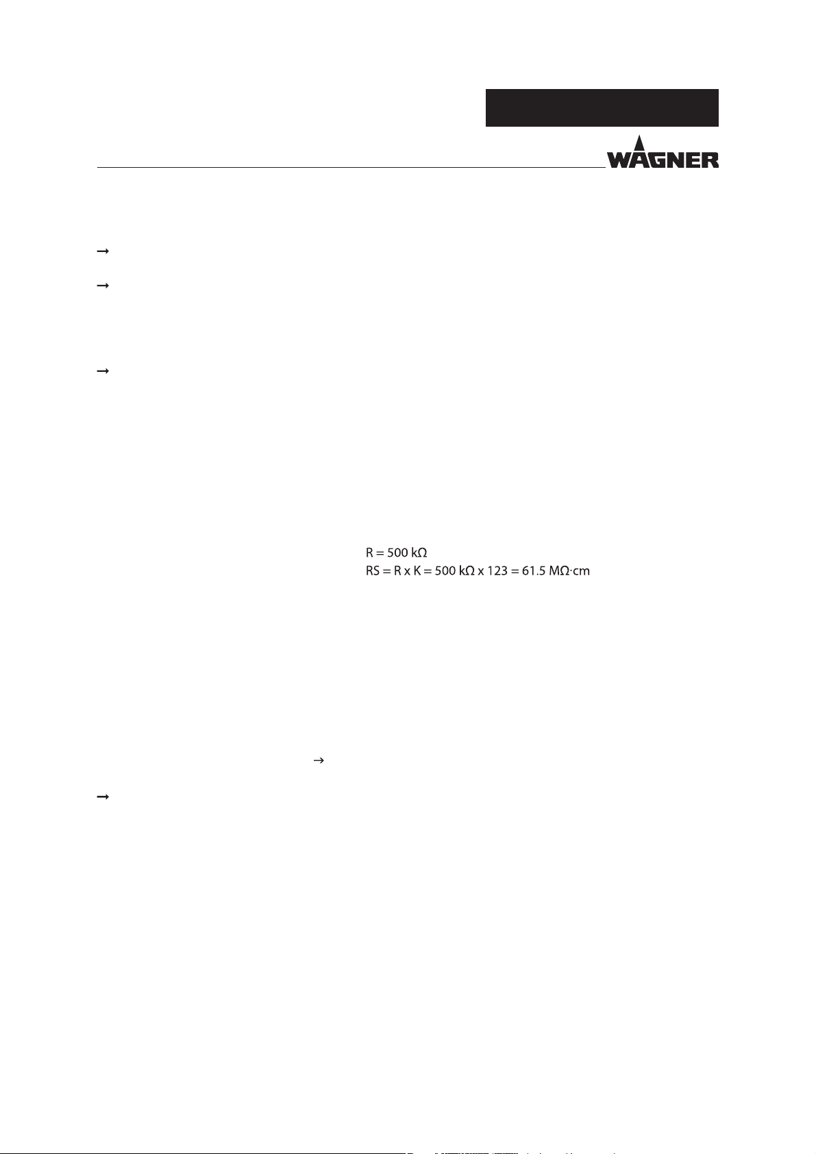
Conversion of Paint Resistance
There are paint resistance measuring devices available on the market that do not directly
measure the speci c paint resistance.
Multiplying the result of the measurement with the device-speci c cell constant (K), we
obtain the speci c resistance value of the product.
Example:
With WAGNER's paint resistance measuring device the cell constant is K =123.
Measured value according to the WAGNER scale
Speci c resistance (RS)
Note:
Using sprayed substances with too low an electrical resistance, the application of
electrostatics does not show any e ect, i.e. there is no "paint wrap around" on the object
to be sprayed.
The suitability of the spray product with regard to the charging ability can be read from the
actual values for high voltage (kV) and for the spray current (μA) shown in the illuminated
displays on the EPG 5000 control unit.
High kV value, low μA value = ok
Low kV value, high μA value = excessive conductivity of the paint
No wrap-around
Please contact your local WAGNER dealer and the lacquer manufacturer if you encounter
application problems.
11
Page 12
VERSION 09/2016 ORDER NUMBER DOC2360922
OPERATING MANUAL
2.6 REASONABLY FORESEEABLE MISUSE
The forms of misuse listed below may result in physical injury or property damage:
use with non-authorized control units;
coating work pieces which are not grounded;
working with an ungrounded lacquer supply system;
performing unauthorized conversions or modi cations to the device;
processing inadmissible coating products;
processing dry or similar coating products, e.g., powder;
using defective components, spare parts or accessories other than those described in
the "Accessories" chapter of this operating manual;
continuing work with a defective or kinked product hose;
working with incorrectly set values;
processing food.
GA 5000EAC
2.7 RESIDUAL RISKS
Residual risks are risks which cannot be ruled out even in the event of correct use.
If necessary, warning and prohibition signs at the relevant points of risk indicate residual
risks.
Residual risk Source Consequences Speci c measures Lifecycle phase
Skin contact with
lacquers and
cleaning agents
Lacquer in air
outside the de ned
working area
Handling of
lacquers and
cleaning agents
Lacquering outside
the de ned working
area
Skin irritations, Wear protective
allergies maintenance,
Inhalation of
substances
hazardous to health
clothing
Observe safety data
sheets
Observe work and
operation instructions
Operation,
disassembly
Operation,
maintenance
12
Page 13
VERSION 09/2016 ORDER NUMBER DOC2360922
GA 5000EAC
OPERATING MANUAL
3 IDENTIFICATION
3.1 CE EXPLOSION PROTECTION IDENTIFICATION
As de ned in the Directive 2014/34/EU (ATEX), the device is suitable for use in potentially
explosive areas.
Device type: GA 5000EAC electrostatic automatic spray gun
Manufacturer: Wagner International AG
CH-9450 Altstätten, Switzerland
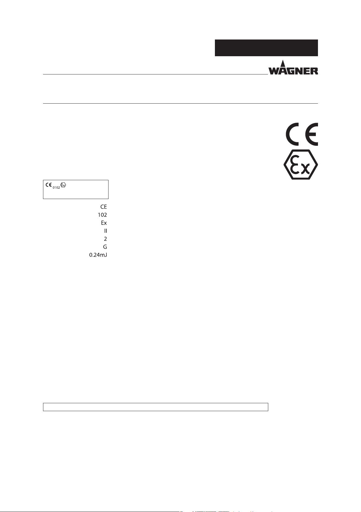
II 2 G 0.24mJ X
SIRA 16 ATEX5290X
European Communities
Noti ed body: PTB
Explosion-proof equipment
Device class II (not mining)
Category 2 device (suitable for zone 1)
Ex-atmosphere gas
Maximum ignition energy
X Special Notes (see Chapter 3.2)
SIRA 16 ATEX 5290X Number of type examination certi cate
3.2 SPECIAL NOTICE "X"
Temperature notes
- Maximum surface temperature: 85 °C; 185 °F
- Maximum permissible product temperature: 50 °C; 122 °F
- Permissible ambient temperature: 0 to +40 °C; +32 to +104 °F
Cable connections
Only cable assigned to the device may be used (see Chapter 13).
Permissible Device Combinations
The GA 5000EAC automatic spray gun may only be connected to the control units listed
below:
- EPG 5000 control unit
13
Page 14

VERSION 09/2016 ORDER NUMBER DOC2360922
OPERATING MANUAL
WARNING
Incorrect use!
Risk of injury and damage to the device.
Connect the GA 5000EAC automatic spray gun only to original
WAGNER control units.
3.3 IDENTIFICATION "X" (TYPE EXAMINATION CERTIFICATE)
Note:
The EC Type Examination Certi cate from SIRA covers the following:
- use of the spray gun in Zone 1;
- use of the EPG 5000 control unit as related equipment for the spray gun.
GA 5000EAC
14
Page 15
VERSION 09/2016 ORDER NUMBER DOC2360922
OPERATING MANUAL
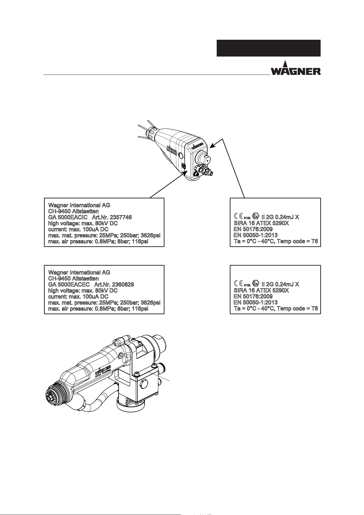
3.4 TYPE PLATE
GA 5000EACIC
GA 5000EAC
B_05768
Serial No.
YY-XXX
GA 5000EACEC
Serial number
15
Page 16
VERSION 09/2016 ORDER NUMBER DOC2360922
OPERATING MANUAL
4 GENERAL SAFETY INSTRUCTIONS
4.1 SAFETY INSTRUCTIONS FOR THE OPERATOR
Keep this operating manual at hand near the device at all times.
Always follow local regulations concerning occupational safety and accident prevention.
4.1.1 ELECTRICAL EQUIPMENT
Electrical devices and equipment
To be provided in accordance with the local safety requirements with regard to the
operating mode and ambient in uences.
May only be maintained by skilled electricians or under their supervision. With open
housings, there is a danger from line voltage.
Must be operated in accordance with the safety regulations and electrotechnical regulations.
Must be repaired immediately in the event of problems.
Must be decommissioned if they pose a hazard or are damaged.
Must be de-energized before work is commenced on active parts. Inform sta about
planned work. Observe electrical safety regulations.
Connect all devices to a common grounding point.
Only operate the device with a properly installed socket with a protective ground wire
connection.
Keep liquids away from electrical devices.
GA 5000EAC
4.1.2 PERSONNEL QUALIFICATIONS
Ensure that the device is only operated, maintained and repaired by trained persons.
4.1.3 SAFE WORK ENVIRONMENT
Ensure that the oor in the working area is static dissipative in accordance with
EN61340-4-1 (resistance must not exceed 100 megohms).
Ensure that all persons within the working area wear static dissipative shoes.
Footwear must comply with EN 20344. The measured insulation resistance must not
exceed 100 megohms.
If protective clothing is worn, including gloves, it has to comply with EN 1149-5.
The measured insulation resistance must not exceed 100 megohms.
Paint mist extraction systems/ventilation systems must be tted on site according to
local regulations.
Ensure that the following components of a safe working environment are available:
- Product/air hoses adapted to the working pressure.
- Personal safety equipment (breathing and skin protection).
16
Page 17
VERSION 09/2016 ORDER NUMBER DOC2360922
OPERATING MANUAL
Ensure that there are no ignition sources such as naked ames, sparks, glowing wires,
or hot surfaces in the vicinity. No smoking.
Ensure that the pipe joints, hoses, equipment parts and connections are permanently,
technically leak-proof:
- Periodic preventative maintenance and service (replacing hoses, checking tightness
strength and connections etc.).
- Regular monitoring of leaks and defects via visual inspection and odor testing, e.g.,
daily before commissioning, at the end of work or weekly.
In the event of defects, immediately bring the device or system to a stop and arrange
to have repairs carried out immediately.
4.2 SAFETY INSTRUCTIONS FOR STAFF
Always follow the information in this manual, particularly the general safety instructions
and the warning instructions.
Always follow local regulations concerning occupational safety and accident prevention.
Anyone tted with a pacemaker must not enter the high-voltage area!
GA 5000EAC
4.2.1 SAFE HANDLING OF WAGNER SPRAY DEVICES
The spray jet is under pressure and can cause dangerous injuries.
Avoid injection of paint or ushing agents:
Never point the spray gun at people.
Never reach into the spray jet.
Before all work on the device, in the event of work interruptions and functional faults:
- Switch o the energy/compressed air supply.
- Relieve the pressure from the spray gun and device.
- Secure the spray gun against actuation.
- In the event of functional faults, remedy the fault as described in the "Troubleshooting"
chapter.
If necessary or at least every 12 months, the liquid ejection devices should be checked for
safe working conditions by an expert (e.g., WAGNER Service Technician) in accordance
with the guidelines for liquid ejection devices (DGUV regulation 100-500).
- For shut down devices, the examination can be suspended until the next start-up.
Carry out the work steps as described in the "Pressure relief" chapter:
- If pressure relief is required.
- If the spraying work is interrupted or stopped.
- Before the device is cleaned on the outside, checked or serviced.
- Before the spray nozzle is installed or cleaned.
In the event of skin injuries caused by paint or ushing agents:
Note the paint or ushing agent that you have been using.
Consult a doctor immediately.
17
Page 18
VERSION 09/2016 ORDER NUMBER DOC2360922
GA 5000EAC
OPERATING MANUAL
4.2.2 GROUNDING THE DEVICE
Friction, owing liquids and air or electrostatic coating processes create charges. Flames or
sparks can form during discharge. Grounding prevents electrostatic charging.
Ensure that the device is grounded. See Chapter "Grounding".
Ground the work pieces to be coated.
Ensure that all persons inside the working area are grounded, e.g., that they are wearing
static dissipative shoes.
The spray substance supply (spray substance tank, pump, etc.) must be grounded.
4.2.3 PRODUCT HOSES
Ensure that the hose material is chemically resistant to the sprayed products and the
used ushing agents.
Ensure that the product hose is suitable for the pressure generated.
Ensure that the following information can be seen on the high-pressure hose:
- Manufacturer
- Permissible operating pressure
- Date of manufacture
Make sure that the hoses are laid only in suitable places. Hoses should not be laid in the
following places under any circumstances:
- in high-traffic areas,
- on sharp edges,
- on moving parts or
- on hot surfaces.
Ensure that the hoses are never run over by vehicles (e.g., fork lifts), or that the hoses are
never put under pressure from the outside in any other way.
Ensure that the hoses are never kinked. Observe maximum bending radii.
Make sure that the hoses are never used to pull or move the equipment.
Suction hoses may not be subjected to pressure.
Several liquids have a high expansion coe cient. In some cases their volume can rise with
consequent damage to pipes, ttings, etc. and cause uid leakage.
When the pump sucks liquid from a closed tank, ensure that air or a suitable gas can
enter the tank. Thus a negative pressure is avoided. The vacuum could implode the tank
(squeeze) and can cause it to break. The tank would leak and the liquid would ow out.
The pressure created by the pump is a multiplication of the inlet air pressure.
18
Page 19

VERSION 09/2016 ORDER NUMBER DOC2360922
OPERATING MANUAL
4.2.4 CLEANING AND FLUSHING
Relieve the pressure from the device.
De-energize the device electrically.
Preference should be given to non- ammable cleaning and ushing agents.
Observe the speci cations of the lacquer manufacturer.
Ensure that the ash point of the cleaning agent is at least 15 K above the ambient
temperature or that cleaning is undertaken at a cleaning station with technical
ventilation.
Take measures for workplace safety (see Chapter 4.1.3).
When commissioning or emptying the device, please note that an explosive mixture
may temporarily exist inside the lines and components of equipment:
- depending on the coating product used,
- depending on the ushing agent (solvent) used,
explosive mixture inside the lines and items of equipment.
Only electrically conductive tanks may be used for cleaning and ushing agents.
The tanks must be grounded.
GA 5000EAC
An explosive gas/air mixture forms in closed tanks.
Never spray into a closed tank when using solvents for ushing.
External cleaning
When cleaning the exterior of the device or its parts, also observe the following:
Disconnect the pneumatic supply line.
Use only moistened cloths and brushes. Never use abrasive agents or hard objects and
never spray cleaning agents with a gun. Cleaning the device must not damage it in any
way.
Ensure that no electrical component is cleaned with nor even immersed into solvent.
Which cleaning agent is used to clean the spray gun depends on which parts of the
spray gun have to be cleaned and which product has to be removed. When cleaning the
spray gun, only use non-polar cleaning agents to prevent conductive residues on the
surface of the spray gun. Should it however, be necessary to use a polar cleaning agent,
all residues of this cleaning agent have to be removed by using a non-conductive and
non-polar cleaning agent, once the cleaning is nished.
19
Page 20
VERSION 09/2016 ORDER NUMBER DOC2360922
OPERATING MANUAL
4.2.5 HANDLING HAZARDOUS LIQUIDS, VARNISHES AND PAINTS
When preparing or working with lacquer and when cleaning the device, follow the
working instructions of the manufacturer of the lacquers, solvents and cleaning agents
being used.
Take the speci ed protective measures, in particular wear safety goggles, protective
clothing and gloves, as well as skin protection cream if necessary.
Use a mask or breathing apparatus if necessary.
For su cient health and environmental safety: Operate the device in a spray booth or
on a spraying wall with the ventilation (extraction) switched on.
Wear suitable protective clothing when working with hot products.
4.2.6 TOUCHING HOT SURFACES
Only touch hot surfaces if you are wearing protective gloves.
When operating the device with a coating product with a temperature of > 43 °C; 109.4 °F:
- Identify the device with a warning label "Warning - hot surface".
Order No.
9998910 Instruction label
9998911 Protection label
Note: Order the two stickers together.
GA 5000EAC
4.3 PROTECTIVE AND MONITORING EQUIPMENT
Protective and monitoring equipment must not be removed, modi ed or rendered
unusable.
Regularly check for perfect functioning.
If defects are detected on protective and monitoring equipment, the system must not
be operated until these defects are remedied.
20
Page 21
VERSION 09/2016 ORDER NUMBER DOC2360922
GA 5000EAC
OPERATING MANUAL
4.4 USE IN AREAS SUBJECT TO EXPLOSION HAZARDS
The spray gun may be used in potentially explosive areas. The following safety regulations
must be observed and followed.
4.4.1 SAFETY REGULATIONS
Observe safety instructions in Chapter 3.2.
Safe handling of WAGNER spray devices
Mechanical sparks can form if the device comes into contact with metal.
In an explosive atmosphere:
Do not knock or push the device against steel or rusty iron.
Do not drop the spray gun.
Use only tools that are made of a permitted material.
Ignition temperature of the coating product
Ensure that the ignition temperature of the coating product is above the maximum
surface temperature.
Surface spraying, electrostatics
Never spray device parts using electrostatic equipment (electrostatic spray gun!).
Medium supporting atomizing
To atomize the product, use only weakly oxidizing gases, e.g., air.
Cleaning
If there are deposits on the surfaces, the device may form electrostatic charges. Flames or
sparks can form during discharge.
Remove deposits from the surfaces to maintain conductivity.
Use only a damp cloth to clean the device.
4.5 SETTING UP STATIONARY ELECTROSTATIC SYSTEMS
The spray gun is a component of a stationary coating system. When setting up stationary
coating systems, comply strictly with EN 50176. One of the requirements is that activation
of the high voltage is only possible by using a key. But it must be possible to switch o the
high voltage without a key.
21
Page 22

VERSION 09/2016 ORDER NUMBER DOC2360922
OPERATING MANUAL
GA 5000EAC
4.6 SAFETYRELEVANT INFORMATION ABOUT DISCHARGES
The plastic parts of the spray gun are charged electrostatically by the high-voltage eld
of the spray gun. Contact with plastic parts harmless discharges (brush discharges) may
occur. They are completely non-hazardous for human health.
When keeping a distance of 4 to 10 mm; 0.15 to 0.4 inches between spray gun and object
to be sprayed, the corona discharge at the end of the electrode is visible in the dark.
22
Page 23

VERSION 09/2016 ORDER NUMBER DOC2360922
OPERATING MANUAL
5 DESCRIPTION
5.1 STRUCTURE STANDARD VARIANT
5.1.1 GA 5000EACIC DESIGN
5
4
3
2
1
GA 5000EAC
6
7
B_05739
1 Front cover
2 Union nut with nozzle protection
3 Air cap
4 Flat jet nozzle
5 Gun adapter
6 Piston housing
7 Rear cover
8 Air di user housing
Connections on the rear side:
5
4
1
2
15
11
12
13
14
9 Shaping air setting
10 Gun holder
11 Product hose
12 Sealing tting
13 Nozzle screw joint
14 Nozzle attachment
15 Round jet nozzle
1 Connection closed with dummy plug
2 Product connection NPSM 1/4"
3 Control air connection (D6/red)
4 Gun cable connection
5 Shaping air or atomizing air connection (D10/blue)
10
8
9
B_05740
3
23
Page 24

VERSION 09/2016 ORDER NUMBER DOC2360922
OPERATING MANUAL
5.1.2 GA 5000EACEC DESIGN
6
5
4
3
2
1
9
10
11
12
B_05740
13
14
GA 5000EAC
7
8
1 Front cover
2 Union nut with nozzle protection
3 Air cap
4 Flat jet nozzle
5 Gun adapter
6 Piston housing
7 Rear cover
Connections on the rear side:
5
4
B_05742
3
1
2
8 Air di user housing
9 Gun holder
10 Product hose
11 Sealing tting
12 Nozzle screw joint
13 Nozzle attachment
14 Round jet nozzle
1 Atomizing air connection (D10/blue)
2 Product connection, G1/4"
3 Control air connection (D6/red)
4 Gun cable connection
5 Shaping air connection (D8/green)
24
Page 25

VERSION 09/2016 ORDER NUMBER DOC2360922
GA 5000EAC
OPERATING MANUAL
5.2 MODE OF OPERATION
Note:
Operation of the spray gun in conjunction with the EPG 5000 control unit is described in
this operating manual.
➞ The high voltage for the GA 5000EAC spray gun is activated directly on the EPG5000
control unit or by a signal from the superordinate controller.
➞ The high voltage for the spray gun can be adapted via the voltage regulator on the
EPG 5000 control unit and can be adjusted to the paint or to the spraying object.
➞ Secure gun:
1. Switch o the mains at the EPG 5000
2. Switch o the air supply at the EPG 5000
3. Relieve the pressure of the spray gun and system
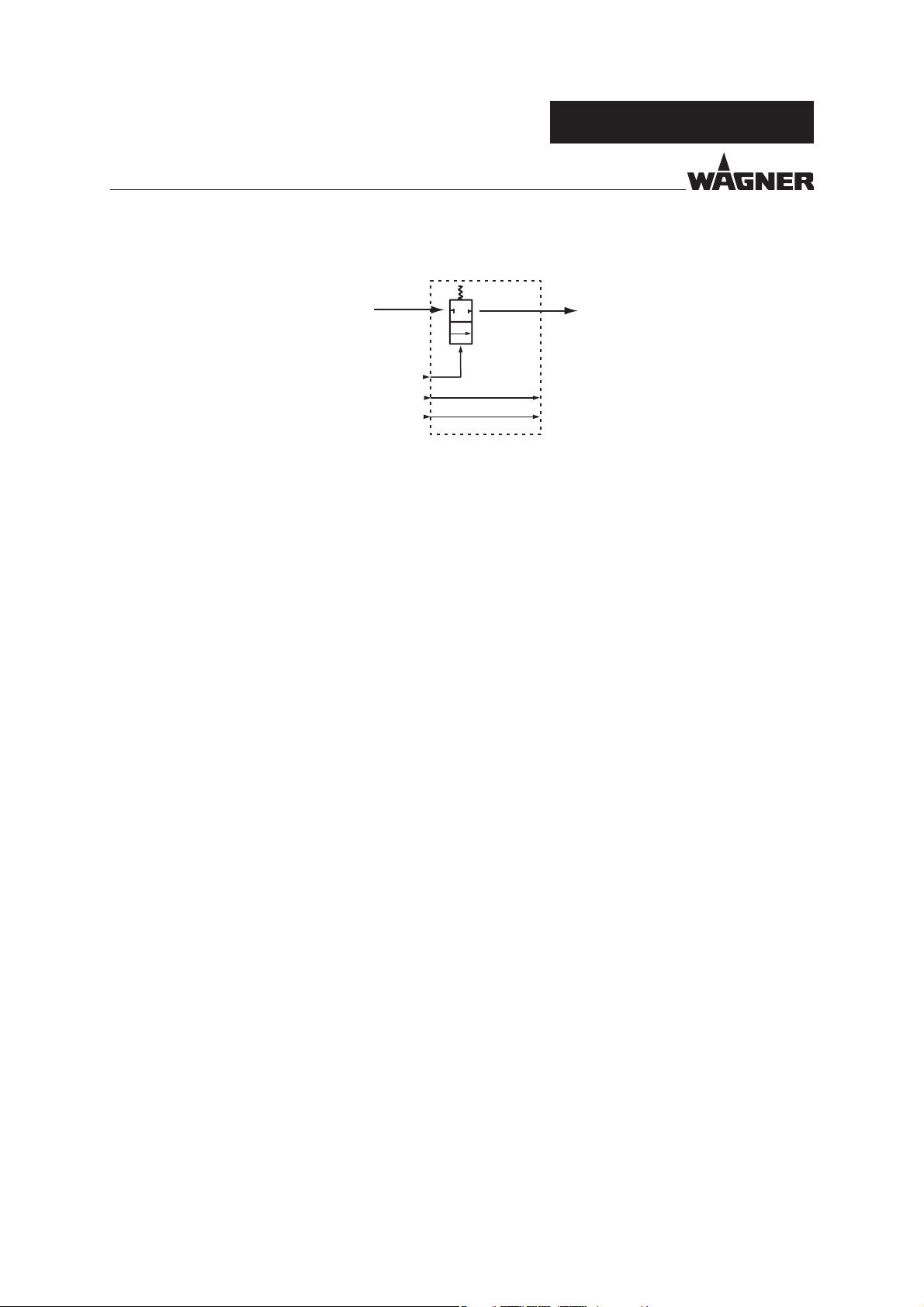
5.2.1 GA 5000EACIC MODE OF OPERATION
Pneumatic diagram:
SA = Shaping air
AA = Atomizing air
CA = Control air
M = Product
Open:
The piston in the drive is charged with control air and moves toward the rear. This ensures
that the air valve which releases the shaping and atomizing air is opened rst. The product
valve is then opened with a mechanical delay. In this position, the pressurized coating
product is applied to the work piece.
Close:
The piston is relieved, and the product valve closes due to the pressure spring which
presses against the product valve tappet. The air valve is then closed, again with a spring
force and mechanical delay.
Additional functions:
The shaping air throttle is used to regulate the shaping air volume, while the atomizing air is
adjusted via an external pressure regulator. The two air streams do not ow separately until
downstream of the air valve, so that the pressure of the shaping air corresponds roughly to
that of the atomizing air and so that they in uence each other during adjustment.
M
AA / SA
CA
B_06007
Nozzle
SA
AA
25
Page 26
VERSION 09/2016 ORDER NUMBER DOC2360922
GA 5000EAC
OPERATING MANUAL
5.2.2 GA 5000EACEC MODE OF OPERATION
Pneumatic diagram:
M
SA = Shaping air
AA = Atomizing air
CA = Control air
M = Product
Open:
First, the external air valve, which enables the shaping and atomizing air, is opened.
The diaphragm in the drive is then charged with control air and moves toward the rear,
opening the product valve. In this position, the pressurized coating product is applied to
the work piece.
CA
SA
AA
B_06008
Nozzle
SA
AA
Close:
If the control air is deactivated, the product valve closes due to the pressure spring.
The air valve is then closed externally.
Additional functions:
The shaping air pressure and the atomizing air pressure are set externally via separate
pressure regulators. Both air ows are supplied separately, which allows them to be set
separately.
26
Page 27
VERSION 09/2016 ORDER NUMBER DOC2360922
GA 5000EAC
OPERATING MANUAL
5.3 PROTECTIVE AND MONITORING EQUIPMENT
The following functions are provided for safety:
- Electrical monitoring of high voltage and spray current (maximum ignition energy 0.24 mJ)
No ignition danger and personnel danger
- Electrical monitoring of the spray gun
- Anti-contact guard for at jet nozzle
WARNING
Protective and monitoring equipment!
Risk of injury and damage to the device.
Protective and monitoring equipment must not be removed,
modi ed or rendered unusable.
Regularly check for perfect functioning.
If defects are detected on protective and monitoring equipment,
the system must not be operated until these defects are remedied.
5.4 SCOPE OF DELIVERY
Order No. Description
2360898 GA 5000EACIC spray gun
2360899 GA 5000EACEC spray gun
The spray guns are delivered without control unit, product and air hose,
electric cable, air cap and nozzle.
Each spray gun includes the following as standard equipment:
Order No. Description
2309368 Valve needle assembly tool
2325263 Clamping screw assembly tool
2360925 Declaration of Conformity for ES 5000 Automatic
2360921 Operating manual German
see Chapter 1.3 Operating manual in local language
The spray gun basic version can be adapted optimally to any application depending upon
the requirements and the desired accessories with the help of spray gun con guration.
The delivery note shows the exact scope of delivery.
27
Page 28
VERSION 09/2016 ORDER NUMBER DOC2360922
GA 5000EAC
OPERATING MANUAL
5.5 TECHNICAL DATA
Control air pressure (open product valve) 0.4–0.8 MPa; 4–8 bar; 58–116 psi
Maximum atomizing air pressure 8 bar; 0.8 MPa; 116 psi
Maximum shaping air pressure 0.8 MPa; 8 bar; 116 psi
Maximum product pressure 250 bar; 25 MPa; 3626 psi
Input voltage maximum 20 Vpp
Input current maximum 1.0 A AC
Maximum output voltage 80 kV
Maximum output current 100 µA
Polarity Negative
Maximum discharge energy 0.24 mJ
Product connection NPSM 1/4"-18
Atomizer air connection D10
Shaping air connection (only for GA 5000EACEC) D8
Control air connection D6
Weight (without houses) 1.0 kg; 2.2 lb
Flow rate
Ambient temperature 0 °C - 40 °C; 32 °F - 104 °F
Maximum product temperature 50 °C; 122 °F
Maximum surface temperature 85 °C; 185 °F
Compressed air quality: free from oil and water
Sound level at 0.3 MPa; 3 bar; 43.5 psi air pressure
and 0.3 MPa; 3 bar; 43.5 psi product pressure *
* A-rated sound pressure level measured at 1 m distance, LpA1m, in accordance with DIN EN 14462: 2005.
according to nozzle size
(see nozzle table in "Accessories" chapter)
Quality standard 6.5.2 according to ISO 8573.1, 2010
6: Particle density ≤ 5mg/m
5: Humidity: pressure dew point ≤ +7°C
2: Oil content ≤ 0.1mg/m
76 dB(A)
28
Page 29
VERSION 09/2016 ORDER NUMBER DOC2360922
OPERATING MANUAL
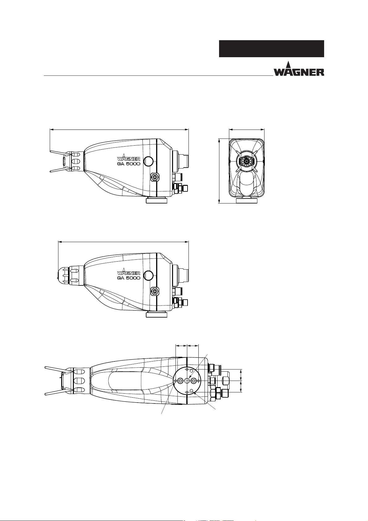
5.5.1 GA 5000EAC DIMENSIONS
GA 5000EAC with at jet nozzle
GA 5000EAC
291
GA 5000EAC with round jet nozzle
274
74
135
B_05748
Connecting dimensions of the connection plate:
B_05761
4x ∅ 3.2
18 18
M8
18 18
2x M5
29
Page 30
VERSION 09/2016 ORDER NUMBER DOC2360922
GA 5000EAC
OPERATING MANUAL
5.6 THE WAGNER ELECTROSTATIC AIRCOAT SPRAYING SYSTEM
The nozzle range (chapter 13) provided by WAGNER allows optimum coating results for
any application.
General criteria for selection of nozzles
Flat jet
Round jet for smaller delicate parts
Options for in uencing the jet spray / spray pattern:
Description Modi cation
Product pressure
Atomizing air pressure + or -
Shaping air regulation from open to closed
for large-surface parts
+ or -
Nozzle sizes
Flow rate
Electrostatics + or - or o
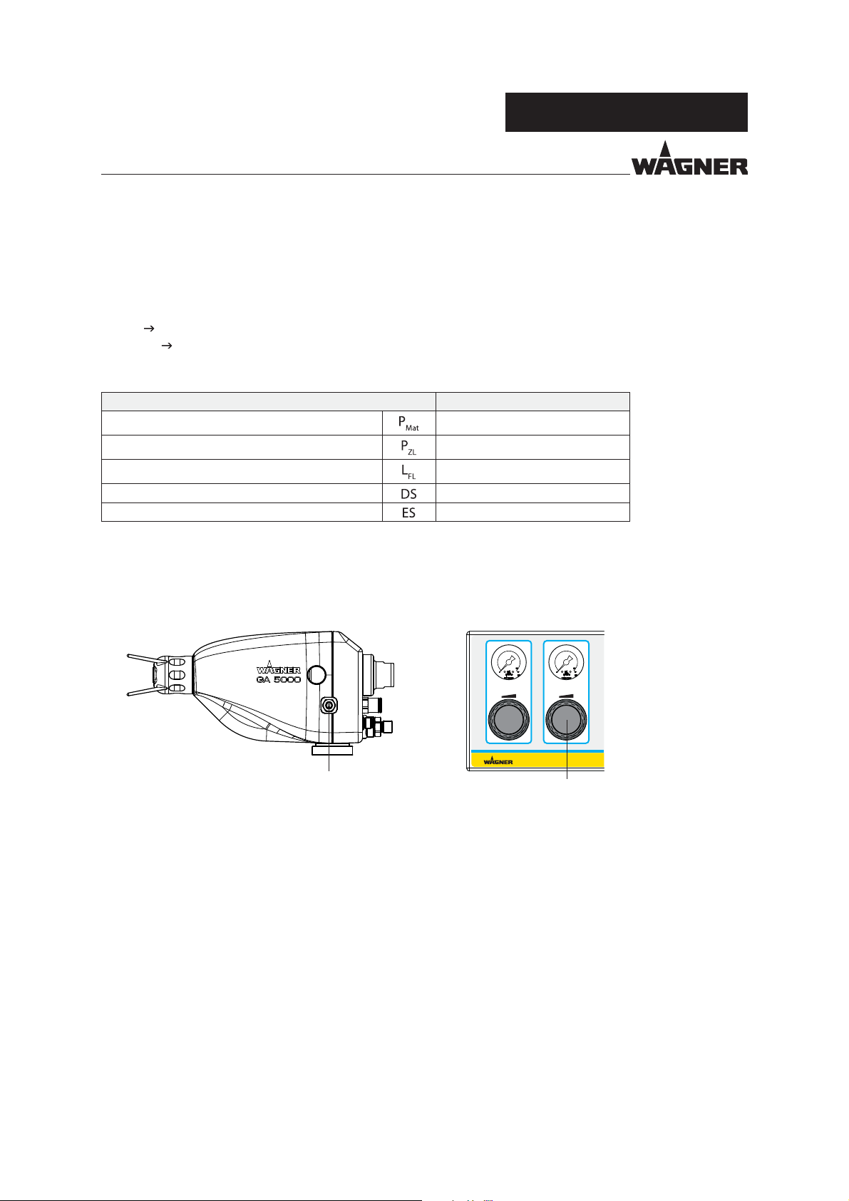
The spray jet width by GA 5000EACIC spray gun is adjusted via the shaping air regulation
(A) on the gun and on the GA 5000EACEC spray gun via the air control knob (B) on the
EPG 5000 control unit in the case of at jet spraying.
GA 5000EACECGA 5000EACIC
Atomizing air
Zerstäuberluft
A
B_05769
Fan air
Formluft
B
30
Page 31

VERSION 09/2016 ORDER NUMBER DOC2360922
GA 5000EAC
OPERATING MANUAL
5.6.1 SPRAYING PROCEDURE FOR AIRCOAT ROUND JET
In the AirCoat process, the spray product is atomized under a pressure of 3-15 MPa; 30-150 bar; 435-2176 psi.
With the help of an air pressure of 0-0.25 MPa; 0-2.5 bar; 0-36 psi, a soft, spray jet is produced. The spray jet
diameter can be adjusted by turning the nozzle nut.
AirCoat air
Advantages
- Large application volume
- Low fogging tendency
- Good nish
- High viscosity products can easily be applied
- High endurance of the nozzles
- Jet width adjustment
Spray product
AirCoat air
"?
Multi-channel swirl nozzle
Nozzle nut
5.6.2 SPRAYING PROCEDURE FOR AIRCOAT FLAT JET
In the AirCoat process, the spray product is atomized under a pressure of 3-15 MPa;
30-150 bar; 435-2176 psi With the help of the AirCoat air, with a pressure of 0-0.25 MPa;
0-2.5 bar; 0-36 psi, a soft, at spray jet is produced which largely eliminates the problem of
overlapping in the peripheral zones. With shaping air, there is the possibility of reducing
the width of the spray jet.
Shaping air
Advantages
- Large application volume
- Low fogging tendency
- Good nish
- High viscosity products can easily be applied
- High endurance of the nozzles
- Jet width adjustment
Variable spray jet width
Spray jet
Air cap
Atomizing air
B_00020
31
Page 32

VERSION 09/2016 ORDER NUMBER DOC2360922
GA 5000EAC
OPERATING MANUAL
5.6.3 ELECTROSTATIC EFFECT
The spray gun produces an electrostatic eld by means of the high-voltage electrode.
As a result, the paint particles atomized by the spray gun are carried to the grounded work
piece by kinetic and electrostatic energy, where they adhere nely dispersed to the object
to be sprayed.
Paint particle
Object to be sprayed is
grounded
Advantages
- Very high application e ectiveness
- Low over spray
- Coating of entire circumferences due to the electrostatic e ect
- Savings in working time
Electrode
"?
32
Page 33

VERSION 09/2016 ORDER NUMBER DOC2360922
OPERATING MANUAL
6 ASSEMBLY AND COMMISSIONING
6.1 TRAINING ASSEMBLY/COMMISSIONING STAFF
WARNING
Incorrect installation/operation!
Risk of injury and damage to the device.
The assembly and commissioning sta must have the technical
skills to safely commission the device.
When assembling, commissioning and carrying out all work,
read and follow the operating manuals and safety regulations
for the additionally required system components.
GA 5000EAC
A skilled person must check to ensure that the device is in a reliable state after it is installed
and commissioned.
6.2 STORAGE CONDITIONS
Until the point of assembly, the device must be stored in a dry location, free from vibrations
and with a minimum of dust. The device must be stored in closed rooms.
The air temperature at the storage location must be between -20 °C and +60 °C (-4 °F and
+140 °F).
The relative air humidity at the storage location must be between 10 and 95% (without
condensation).
6.3 INSTALLATION CONDITIONS
The air temperature at the installation site must be in a range between 0 °C and 40 °C; 32 °F
and 132 °F.
The relative air humidity at the installation site must be between 10 and 95% (without
condensation).
33
Page 34

VERSION 09/2016 ORDER NUMBER DOC2360922
OPERATING MANUAL
GA 5000EAC
6.4 ASSEMBLY AND INSTALLATION
6.4.1 TYPICAL ELECTROSTATIC SPRAYING SYSTEM
The GA 5000EAC spray gun must be combined with various components to make up a
spraying system. The system shown in the gure is only one example of an electrostatic
AirCoat spraying system. Your WAGNER distributor would be happy to assist you in
creating a spraying system solution that meets your individual needs. You must familiarize
yourself with the operating manuals and the safety regulations of all additional system
components before starting commissioning.
WARNING
Incorrect installation/operation!
Risk of injury and damage to the device.
When commissioning and for all work, read and follow the
operating manual and safety regulations for the additionally
required system components.
34
Page 35

VERSION 09/2016 ORDER NUMBER DOC2360922
OPERATING MANUAL
F
GA 5000EAC
A
B_05775
A Spray booth
B Controller
C Reciprocator
D Electrostatic spray gun
E Work piece
f Conveyor
D
E
C
B
35
Page 36

VERSION 09/2016 ORDER NUMBER DOC2360922
OPERATING MANUAL
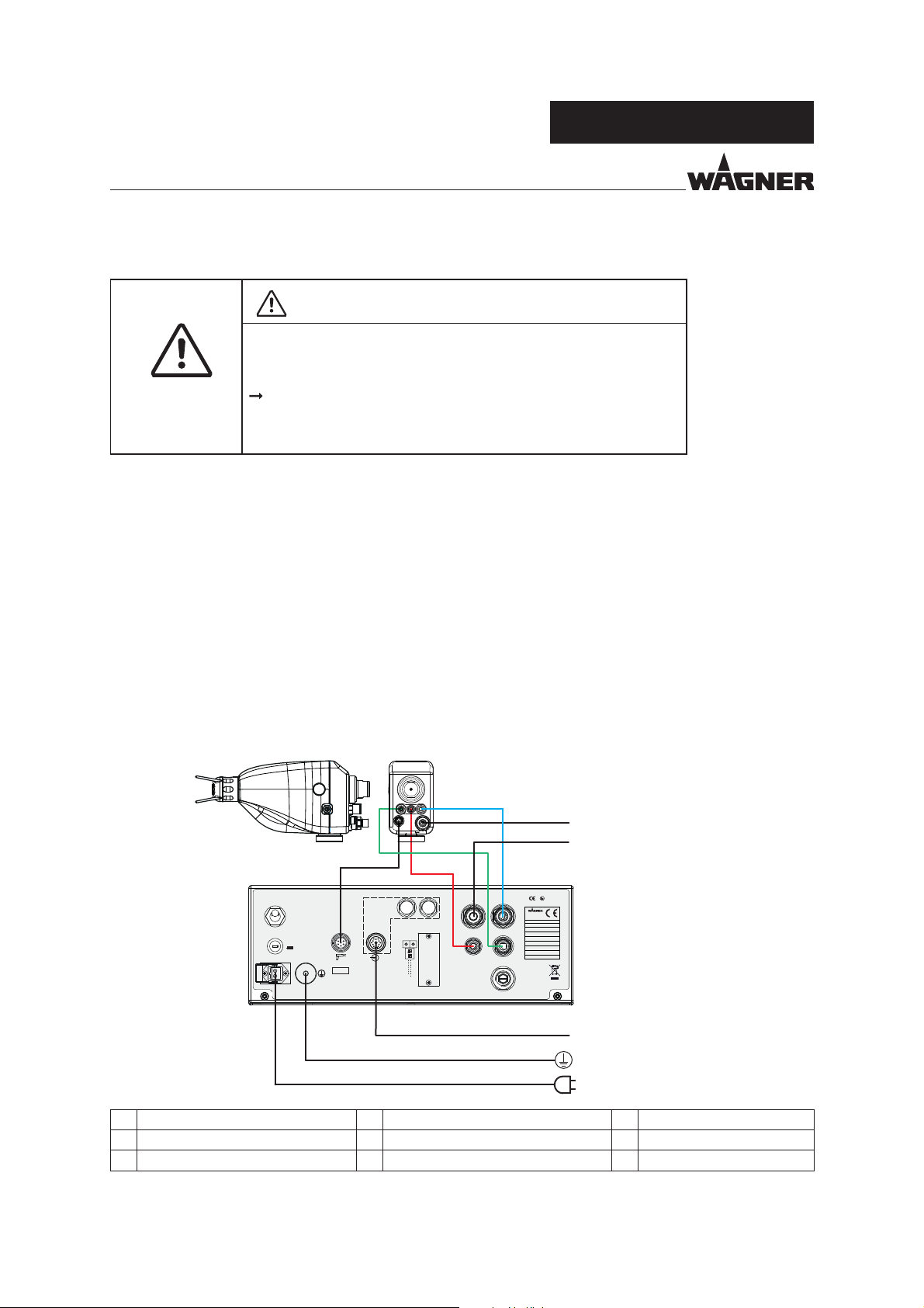
6.4.2 CONNECTING GA 5000EACIC
WARNING
Incorrect installation/operation!
Risk of injury and damage to the device.
When commissioning and for all work, read and follow the
operating manual and safety regulations for the additionally
required system components.
Procedure:
1. Place the control unit outside the explosion zone.
2. Mount spray gun to an grounded gun mounting.
3. Connect the grounding cable to the control unit and the signal ground.
4. Connect the gun connection cable to the control unit.
5. Connect the control unit to the higher-level controller (if available).
6. Connect the air hoses to the control unit and the spray gun in accordance with the
gure below.
7. Set all airs to "0" using the regulator on the front side of the control unit.
8. Connect the control unit to the compressed air supply.
9. Connect the spray gun to the product supply system.
10. Connect the control unit to the power supply.
GA 5000EAC
GA 5000
1
5
II (2) G
0102
2359451
115VAC - 230VAC
50Hz / 60Hz
max. 40W
max. 0.5A
IP 40
EN 50176:2009
EN 50050-1:2013
EPG 5000
Main Switch
Hauptschalter
I
0
Prim. Fuse
Sicherung
1.0 AT
Mains power IN
Netz Eingang
Spraygun
Sprühpistole
Umax. = 20Vpp
Imax. = 1.0A
4
Interface
Schnittstelle
IN CAN Bus OUT
Data and Interlock
Daten und Verriegelung
CAN
Address
5
5
6
6
4
4
7
7
3
3
8
8
2
2
9
9
1
1
0
0
Service
Port
3
Air input
Atomizing air
Lufteingang
Zerstäuberluft
SIRA 16 ATEX 5290X
Wagner International AG
Industriestrasse 22
CH - 9450 Altstätten
Made in Switzerland
Typ / Type: EPG 5000
Artikel Nr.:
Article No.:
Serie Nr.:
Serial No.:
Fan air
Control air
Steuerluft
Air input
6 - 8bar
87-116 psi
Clean and dry air
Saubere und trockene Luft
6.5.2 (ISO 8573-1:2010)
Restrictor for air during cleaning
Drossel für Luft während dem Spülen
Formluft
B_05743
Baujahr:
Year of manufacture:
Spannung:
Voltage:
Eingangsleistung:
Input Power:
Eingangsstrom:
Input Current:
Schutzart:
IP Code:
Norm:
Standard:
2
6
7
8
1 for the product supply system 4 Gun cable 7 Grounding cable
2 Shaping air and atomizing air hose 5 for the compressed air supply 8 Mains cable
3 Control air hose 6 Control cable
36
Page 37
VERSION 09/2016 ORDER NUMBER DOC2360922
OPERATING MANUAL
6.4.3 CONNECTING GA 5000EACEC
WARNING
Incorrect installation/operation!
Risk of injury and damage to the device.
When commissioning and for all work, read and follow the
operating manual and safety regulations for the additionally
required system components.
Procedure:
1. Place the control unit outside the explosion zone.
2. Mount spray gun to an grounded gun mounting.
3. Connect the grounding cable to the control unit and the signal ground.
4. Connect the gun connection cable to the control unit.
5. Connect the control unit to the higher-level controller (if available).
6. Connect the air hoses to the control unit and the spray gun in accordance with the
gure below.
7. Set all airs to "0" using the regulator on the front side of the control unit.
8. Connect the control unit to the compressed air supply.
9. Connect the spray gun to the product supply system.
10. Connect the control unit to the power supply.
GA 5000EAC
GA 5000
2
1
6
II (2) G
0102
2359451
115VAC - 230VAC
50Hz / 60Hz
max. 40W
max. 0.5A
IP 40
EN 50176:2009
EN 50050-1:2013
EPG 5000
Main Switch
Hauptschalter
I
0
Prim. Fuse
Sicherung
1.0 AT
Mains power IN
Netz Eingang
Spraygun
Sprühpistole
Umax. = 20Vpp
Imax. = 1.0A
5
Interface
Schnittstelle
IN CAN Bus OUT
Data and Interlock
Daten und Verriegelung
CAN
Address
5
5
6
6
4
4
7
7
3
3
8
8
2
2
9
9
1
1
0
0
Service
Port
4
Air input
Atomizing air
Lufteingang
Zerstäuberluft
SIRA 16 ATEX 5290X
Wagner International AG
Industriestrasse 22
CH - 9450 Altstätten
Made in Switzerland
Typ / Type: EPG 5000
Artikel Nr.:
Article No.:
Serie Nr.:
Serial No.:
Fan air
Control air
Steuerluft
Air input
6 - 8bar
87-116 psi
Clean and dry air
Saubere und trockene Luft
6.5.2 (ISO 8573-1:2010)
Restrictor for air during cleaning
Drossel für Luft während dem Spülen
Formluft
B_05727
Baujahr:
Year of manufacture:
Spannung:
Voltage:
Eingangsleistung:
Input Power:
Eingangsstrom:
Input Current:
Schutzart:
IP Code:
Norm:
Standard:
3
7
8
9
1 for the product supply system 4 Control air hose 7 Control cable
2 Shaping air hose 5 Gun cable 8 Grounding cable
3 Atomizing air hose 6 for the compressed air supply 9 Mains cable
37
Page 38

VERSION 09/2016 ORDER NUMBER DOC2360922
GA 5000EAC
OPERATING MANUAL
6.4.4 VENTILATION OF THE SPRAY BOOTH
The electrostatic spraying equipment may only be operated in de ned spraying areas and
in accordance with the EN 12215 standard or under comparable ventilation conditions.
The electrostatic spraying equipment must be locked to the technical ventilation so that
the coating product supply and the high voltage are not e ective as long as the technical
ventilation is not operated with the minimum exhaust air volume ow or a larger exhaust
air volume ow.
Ensure that the excess coating product (overspray) will be collected up safely.
WARNING
Toxic and/or ammable vapor mixtures!
Risk of poisoning and burns.
Operate the device in a spray booth approved for the working
materials.
-or Operate the device on an appropriate spraying wall with the
ventilation (extraction) switched on.
Observe national and local regulations for the exhaust air speed.
38
Page 39
VERSION 09/2016 ORDER NUMBER DOC2360922
OPERATING MANUAL
GA 5000EAC
6.4.5 AIR SUPPLY
The use of an air lter with air regulator ensures that only dry, clean atomizing air gets into
the spray gun. Dirt and moisture in the atomizing air worsens the spraying quality and
spray pattern.
WARNING
Hose connections!
Risk of injury and damage to the device.
Do not exchange hose connections of product hose and air hose.
6.4.6 PRODUCT SUPPLY
NOTICE
Impurities in the spraying system!
Spray gun blockage, products harden in the spraying system.
Flush the spray gun and paint supply with a suitable ushing agent.
DANGER
Bursting hose, bursting threaded joints!
Danger to life from injection of product.
Ensure that the hose material is chemically resistant to the
sprayed products.
Ensure that the spray gun, threaded joints and product hose
between the device and the spray gun are suitable for the
pressure generated in the device.
Ensure that the following information can be seen on the high-
pressure hose:
- Manufacturer
- Permissible operating pressure
- Date of manufacture.
39
Page 40

VERSION 09/2016 ORDER NUMBER DOC2360922
GA 5000EAC
OPERATING MANUAL
6.4.7 GROUNDING
Perfect grounding of all conductive parts such as oors, walls, roofs, barriers, work pieces,
transport devices, coating product tank, coating product supply or construction parts
in the spray area with exception of the high-voltage parts during normal operation is
important for optimum coating and safety.
Parts of the booth must be grounded in accordance with EN 12215.
WARNING
Discharge of electrostatically charged components in
atmospheres containing solvents!
Explosion hazard from electrostatic sparks or ames.
Ground all device components.
Ground the work pieces to be coated.
WARNING
Heavy paint mist if grounding is insu cient!
Danger of poisoning.
Insu cient paint application quality.
Ground all device components.
Ground the work pieces to be coated.
A poorly grounded work piece causes:
- very bad wrap around,
- uneven coating,
- back spraying to the spray gun (contamination) and coater.
Prerequisites for perfect grounding and coating are:
- Clean work piece suspension.
- Grounding of spray booth, conveyor system and suspension on the building side in
accordance with the operating manuals or the manufacturer's information.
- Grounding of all conductive parts within the working area.
- The grounding resistance of the work piece must not exceed 1 MΩ (megohm).
(Resistance to ground measured at 500 V or 1000 V).
- Connect the control unit to the signal ground.
- Mount spray gun to an grounded gun mounting.
- Connect all ground cables using a short and direct route.
- Safety shoes must be static dissipative.
40
Page 41
VERSION 09/2016 ORDER NUMBER DOC2360922
OPERATING MANUAL
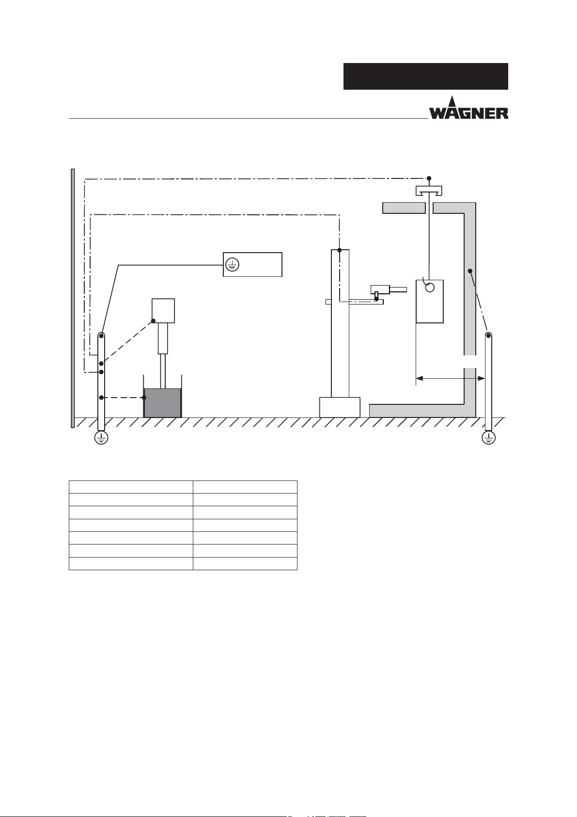
Grounding scheme (example)
Control unit
Grounding cable
Pump
GA 5000EAC
Conveyor
Work piece
Paint tank
B_00137
Minimum cable cross-section
Control unit 4 mm² (AWG 12)
Pump 4 mm² (AWG 12)
Paint tank 4 mm² (AWG 12)
Reciprocator 16 mm² (AWG 6)
Conveyor 16 mm² (AWG 6)
Booth 16 mm² (AWG 6)
Spraying stand 16 mm² (AWG 6)
Signal ground Signal ground
Floor, static dissipative
Spraying stand
Rmax < 1MΩ
41
Page 42

VERSION 09/2016 ORDER NUMBER DOC2360922
GA 5000EAC
OPERATING MANUAL
6.5 PREPARATION OF LACQUER
The viscosity of the lacquer is of great importance. The best spraying results are obtained
with values between 25 and 40 DIN/4 seconds (measured in immersion ow cup DIN 4 mm;
0.16 inches).
Processing of up to 60 DIN/4 seconds is generally possible without problem if high coating
thicknesses are required.
With the WAGNER AirCoat at jet spraying process, the di erent viscosities of the lacquer
are optimally covered by two air cap types. These can be found in "Accessories".
In the case of application problems contact the lacquer manufacturer.
6.5.1 VISCOSITY CONVERSION TABLE
mPa s
10 10 0.1 5 16
15 15 0.15 8 17
20 20 0.2 10 18
25 25 0.25 14 12 19
30 30 0.3 15 14 20
40 40 0.4 17 18 22
50 50 0.5 19 22 24
60 60 0.6 21 26 27
70 70 0.7 23 28 30
80 80 0.8 25 31 34
90 90 0.9 28 32 37
100 100 1 30 34 41
120 120 1.2 33 41 49
140 140 1.4 37 45 58
160 160 1.6 43 50 66
180 180 1.8 46 54 74
200 200 2 49 58 82
220 220 2.2 52 62
240 240 2.4 56 65
260 260 2.6 62 68
280 280 2.8 65 70
300 300 3 70 74
320 320 3.2
340 340 3.4
360 360 3.6 80
380 380 3.8
400 400 4 90
42
Page 43

VERSION 09/2016 ORDER NUMBER DOC2360922
OPERATING MANUAL
6.6 COMMISSIONING
6.6.1 SAFETY INSTRUCTIONS
Observe the safety instructions in Chapter 4 and Chapter 7.2.
Observe the general rules for making adjustments to the spray gun Chapter 7.2.2.
6.6.2 PREPARATION FOR COMMISSIONING
NOTICE
Impurities in the spraying system!
Spray gun blockage.
Flush the spray gun and paint supply with a suitable ushing agent before
commissioning.
GA 5000EAC
6.6.3 COMMISSIONING
The following points should be noted before commissioning:
Make sure that all other conductive parts within the work area are grounded.
Lock the external release with the exhaust air unit.
Lock the external release with an appropriate tool (e.g., key switch) (the high-voltage
supply must be secured to prevent unauthorized persons from switching it on).
Check that all product-conveying connections are correctly connected.
Check that all air-conveying connections are correctly connected.
Visually check the permissible pressures for all the system components.
Check the level of the separating agent in the pump and ll up if necessary.
Provide product tank, tanks for ushing agent and an empty tank for return ow.
The interface on the rear of the control unit must be protected with a cover.
Connect the system to the air supply.
When rst commissioning the unit Flush the system in accordance with the operating
manuals for the other components.
43
Page 44

VERSION 09/2016 ORDER NUMBER DOC2360922
OPERATING MANUAL
GA 5000EAC
6.7 VERIFYING A SAFE OPERATIONAL CONDITION
A skilled person must check to ensure that the device and the spraying system are in a safe
state after they are installed and commissioned.
This includes:
– Carry out a safety checks in accordance with Chapter 8.2.3.
– Function test in accordance with Chapter 11.
44
Page 45

VERSION 09/2016 ORDER NUMBER DOC2360922
OPERATING MANUAL
7 OPERATION
7.1 TRAINING THE OPERATING STAFF
WARNING
Incorrect operation!
Risk of injury and damage to the device.
The operating sta must be quali ed to operate the entire
system.
The operating sta must be familiar with the potential risks
associated with improper behavior as well as the necessary
protective devices and measures.
Before work commences, the operating sta must receive
appropriate system training.
GA 5000EAC
7.2 SAFETY INSTRUCTIONS
Observe safety instructions in Chapter 4.
WARNING
Incorrect operation!
Risk of injury and damage to the device.
If contact with lacquers or cleaning agents causes skin irritation,
appropriate precautionary measures must be taken, e.g.,
wearing protective clothing.
The footwear worn by operating sta must comply with
EN ISO 20344. The measured insulation resistance must not
exceed 100megohms.
The protective clothing, including gloves, must comply with
EN ISO 1149-5. The measured insulation resistance must not
exceed 100 megohms.
WARNING
Unintentional putting into operation!
Risk of injury.
Before any work on the device, in the event of work interruptions
and malfunctions:
Switch o the energy/compressed air supply.
Relieve the pressure from the spray gun and unit.
Secure the spray gun against actuation.
In the event of functional faults: remedy the fault as described in
the "Troubleshooting" chapter.
45
Page 46

VERSION 09/2016 ORDER NUMBER DOC2360922
OPERATING MANUAL
GA 5000EAC
WARNING
Discharge of electrostatically charged components in
atmospheres containing solvents!
Explosion hazard from electrostatic spark-over.
Use gun only with tted nozzle, air cap and union nut.
Tighten the union nut, especially with nozzle in the cleaning
position.
7.2.1 EMERGENCY DEACTIVATION
In the case of unforeseen occurrences, proceed as follows:
1. Switch o control unit.
2. Close the compressed air supply.
3. Relieve pressure according to the operating manual of the product pressure generator.
7.2.2 GENERAL RULES FOR MAKING ADJUSTMENTS TO THE SPRAY GUN
DANGER
High-voltage eld!
Danger to life from malfunction of heart pacemakers.
Make sure that persons with pacemakers:
Do not work with the electrostatic spray gun.
Do not enter the high-voltage area.
WARNING
High-pressure spray jet!
Danger to life from injecting paint or solvent.
Never reach into the spray jet.
Never point the spray gun at people.
Consult a doctor immediately in the event of skin injuries caused
by paint or solvent. Inform the doctor about the paint or solvent
used.
Never seal defective high-pressure parts; instead relieve the pressure
from them and replace them immediately.
Wear the appropriate protective clothing, gloves, eyewear and
respiratory protection.
46
Page 47

VERSION 09/2016 ORDER NUMBER DOC2360922
OPERATING MANUAL
GA 5000EAC
7.3 WORKING
7.3.1 SETTING THE SPRAY PATTERN USING THE AIR PRESSURE REGULATOR
The air pressure regulator regulates the air supply (shaping and atomizing air) to the gun.
B_00071
No air Correct amount of airNot enough air
Spray pattern and air regulation
When IC variant the air regulation regulates the ratio of shaping/atomizing air.
When IC variant the shaping and atomizing air are set individually.
The spray pattern can then be adjusted to suit the object being sprayed. The illustration
shows the in uence of the regulator on the spray pattern.
Other nozzle sizes can be used to obtain larger or smaller spray patterns.
+-
Air regulation fully opened
= maximum shaping air
Changing the Flow Rate
Adapt product pressure
Use a di erent nozzle (see Chapter 13)
Changing the Spray Jet Width
Use a di erent nozzle (see Chapter 13)
B_05762
Air regulation closed
= minimum shaping air
47
Page 48

VERSION 09/2016 ORDER NUMBER DOC2360922
GA 5000EAC
OPERATING MANUAL
7.3.2 SPRAYING
1. Secure gun (switch o controller) and insert the desired nozzle.
2. Turn on the control unit.
3. Start up with product supply set to approx. 8 MPa; 80 bar; 1160 psi operating pressure.
See corresponding operating manual.
AirLess spraying
4. Turn both air pressure regulators at the control unit all the way down.
5. Spray on a test object (switch on the controller).
6. Adjust the product pressure and gun air in accordance with the nozzle and object.
AirCoat spraying
7. When IC variant open the air pressure regulator (approx. 0.05–0.25 MPa; 0.5–2.5 bar;
7–36 psi) and adjust for optimal atomization.
When EC variant set shaping and atomizing air on the pressure regulators.
Flat-jet method: Changing the spray jet width
8. Change the spray jet width by selecting the appropriate nozzle.
By turning the air regulation (1), the spray jet can additionally be adjusted
(IC variant).
Increase or decrease shaping air (EC variant)
See corresponding operating manual.
Round-jet method
8. By gently turning the nozzle nut (2), the atomizing air jet can additionally
be adjusted.
Do not fully tighten the nozzle nut:
Do not turn the nozzle nut (2) until it is ush with the nozzle body (3).
There must be play for the atomizing air between the nozzle nut and
the nozzle body.
Flow rate
9. The ow rate can be reduced by:
- Minimizing the product pressure.
- Use a di erent nozzle (see Chapter 13).
B_05776
1
2
3
B_05777
48
Page 49

VERSION 09/2016 ORDER NUMBER DOC2360922
OPERATING MANUAL
7.3.3 PRESSURE RELIEF/WORK INTERRUPTION
The pressure must always be relieved when:
- The spraying tasks are nished.
- The spraying system is maintained.
- Cleaning tasks are carried out on the spraying system.
- The spraying system is moved to another location.
- Something must be checked on the spraying system.
- The valve seat is replaced on the gun.
Observe general safety instructions in Chapter 4.
WARNING
High-pressure spray jet!
Danger to life from injecting paint or solvent.
GA 5000EAC
Never reach into the spray jet.
Never point the spray gun at people.
Consult a doctor immediately in the event of skin injuries caused
by paint or solvent. Inform the doctor about the paint or solvent
used.
Never seal defective high-pressure parts; instead relieve the pressure
from them and replace them.
Wear the appropriate protective clothing, gloves, eyewear and
respiratory protection.
Process for relieving pressure
1. Switch o high voltage at the control unit.
2. Turn compressed air supply for shaping and atomizing air on the EPG 5000 to "0".
3. Close the compressed air supply on the material side upon the product pressure
generator.
4. Relieve the pressure of gun and system, e.g., by switching on gun without high voltage.
5. Filling ushing agent.
6. Thoroughly ush out the spray gun.
7. Relieve the pressure on the gun and the system.
8. Clean gun and dry it with a cloth or a blow gun.
49
Page 50
VERSION 09/2016 ORDER NUMBER DOC2360922
OPERATING MANUAL
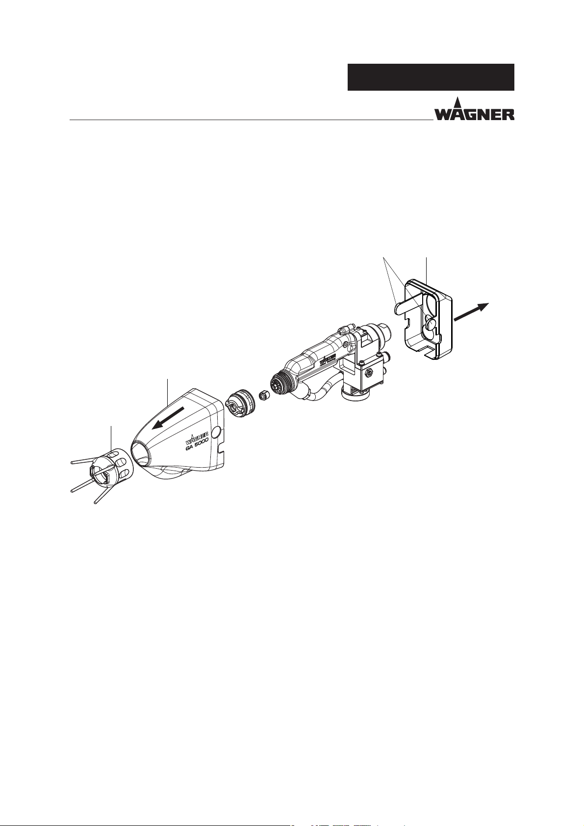
7.3.4 DISMANTLING THE GUN COVER
Note:
For changing nozzles, the cover does not have to be removed!
1. Press the snap t (2) together and pull o the rear cover (1) to the back.
2. Unscrew union nut (3) and pull o front cover (4) to the front.
GA 5000EAC
12
4
3
B_06006
50
Page 51
VERSION 09/2016 ORDER NUMBER DOC2360922
OPERATING MANUAL
7.3.5 FLUSHING OUT CLOGGED ROUND JET NOZZLES
DANGER
Exploding gas / air mixture!
Danger to life from ying parts and burns.
Never spray into a closed tank.
Ground the tank.
1. Remove nozzle insert (1) completely using nozzle
spanner (2).
2. Actuate spray gun brie y.
3. Blow out and clean nozzle opposite the spraying
direction.
4. After ushing, re-tighten the nozzle insert.
GA 5000EAC
1/2
7.3.6 REPLACING ROUND JET NOZZLE'S NOZZLE INSERT
1. Remove nozzle insert (1) using nozzle spanner (2).
2. Assembling new nozzle insert.
1
2
1
2
B_05772
B_05773
51
Page 52

VERSION 09/2016 ORDER NUMBER DOC2360922
GA 5000EAC
OPERATING MANUAL
7.3.7 CHANGING FROM AIRCOAT ROUND JET TO AIRCOAT FLAT JET
Flush spray gun
1. Switch o control unit.
2. Relieve pressure
3. Connect the system to the ushing agent supply.
4. Set product pressure. Close air pressure regulator.
5. Thoroughly ush out the spray gun.
6. Relieve pressure
Changing from round jet to at jet
7. Unscrew round jet nozzle attachment (2) incl. nozzle insert (3).
8. Unscrew nozzle insert (3) using nozzle spanner (4).
9. Unscrew nozzle nut (5). Remove nozzle screw joint (7) and sealing tting (8) from the
nozzle body (6). Thoroughly clean all parts.
10. Insert desired ACF5000 nozzle (11) into the valve housing.
11. Put the air cap (10) on the nozzle (11) and pay attention to the position of the guide
surfaces.
12. Screw union nut with attached nozzle guard (9) to the gun body and make sure that
the air cap horns lie in the designated recess (Y).
13. Before tightening with the air cap horns (Y), set the desired jet level and then tighten
the union nut to stop by hand.
Chapter 7.3.3.
Chapter 7.3.3.
Changing from at jet to round jet
7. Unscrew union nut (9) with air cap (10) and ACF5000 nozzle (11).
8. Remove air cap (10).
9. Press ACF5000 nozzle (11) out of air cap (10) by hand. Thoroughly clean all parts.
10. Insert nozzle screw connection (7) and sealing tting (8) into nozzle body (6).
11. Screw nozzle nut (5) onto nozzle body (6).
Do not screw on nozzle nut completely. There must be play for the atomizing air
between the nozzle nut and the nozzle body.
12. Screw on nozzle insert (3) using nozzle spanner (4).
13. Screw round jet nozzle attachment (2) with nozzle insert (3) onto spray gun and tighten
by hand.
52
Page 53

VERSION 09/2016 ORDER NUMBER DOC2360922
OPERATING MANUAL
1
2
GA 5000EAC
4
3
8
7
6
5
1
11
10
9
Y
B_05754
53
Page 54

VERSION 09/2016 ORDER NUMBER DOC2360922
GA 5000EAC
OPERATING MANUAL
7.3.8 REPLACING THE AIRCOAT FLAT JET NOZZLES
1. Switch o control unit.
2. Unscrew union nut completely (12) and remove air cap (10).
3. Remove and clean the ACF 5000 AirCoat nozzle (11).
NOTICE
Defective AirCoat nozzle!
Insu cient paint application quality.
Do not use sharp-edged objects to treat carbide on the AirCoat nozzle.
4. Insert new ACF5000 nozzle (11) into the valve housing.
5. Put the air cap (10) on the nozzle (11) and pay attention to the position of the guide
surfaces.
6. Screw union nut with attached nozzle guard (9) to the gun body and make sure that
the air cap horns lie in the designated recess (Y).
7. Before tightening with the air cap horns (Y), set the desired jet level and then tighten
the union nut to stop by hand.
1
11
Y
9
10
12
B_05755
54
Page 55

VERSION 09/2016 ORDER NUMBER DOC2360922
OPERATING MANUAL
GA 5000EAC
7.3.9 CLEANING OF THE NOZZLE PARTS
The nozzle parts may only be immersed into a cleaning solvent recommended by the
manufacturer and must be removed again immediately. They may only remain in a
cleaning solvent for a short time.
Clean these parts with a brush and dry them with a cloth or a blow gun.
55
Page 56

VERSION 09/2016 ORDER NUMBER DOC2360922
GA 5000EAC
OPERATING MANUAL
7.3.10 ELIMINATE NOZZLE CLOGGING
1. Switch control unit to standby operation.
2. Unscrew union nut completely (12) and remove air cap (10).
3. Push ACF 5000 nozzle (11) out of air cap (10) by hand, reverse it and put it into the air
cap (10) with the nozzle tip towards the rear.
Pay attention to the position of the guide surfaces (X).
4. Insert air cap (10) with integrated ACF5000 nozzle (11) into the union nut (9).
Make sure that the air cap horns (Y) lie in the recess of the nozzle guard.
5. Screw preassembled union nut (12) to gun (1) and tighten by hand.
6. Switch on gun without high voltage and ush gun.
7. When the blockage has been ushed out, switch control unit back to standby operation.
8. Unscrew union nut (12) completely.
9. Remove air cap (10) and push ACF5000 nozzle (11) out of the air cap by hand.
Clean ACF5000 nozzle and insert it in the spraying position into the valve housing.
10. Put the air cap (10) on the nozzle (11) and pay attention to the position of the guide
surfaces (X).
11. Screw union nut with attached nozzle guard (9) to the gun body and make sure that
the air cap horns lie in the designated recess (Y).
12. Before tightening with the air cap horns (Y), set the desired jet level and then tighten
the union nut to stop by hand.
13. Switch control unit to the required operating mode.
56
Page 57

VERSION 09/2016 ORDER NUMBER DOC2360922
OPERATING MANUAL
1
X
Y
11
GA 5000EAC
Y
9
ACF5000 nozzle in
spray position
ACF5000 nozzle in
cleaning position
10
B_05774
12
12
57
Page 58

VERSION 09/2016 ORDER NUMBER DOC2360922
OPERATING MANUAL
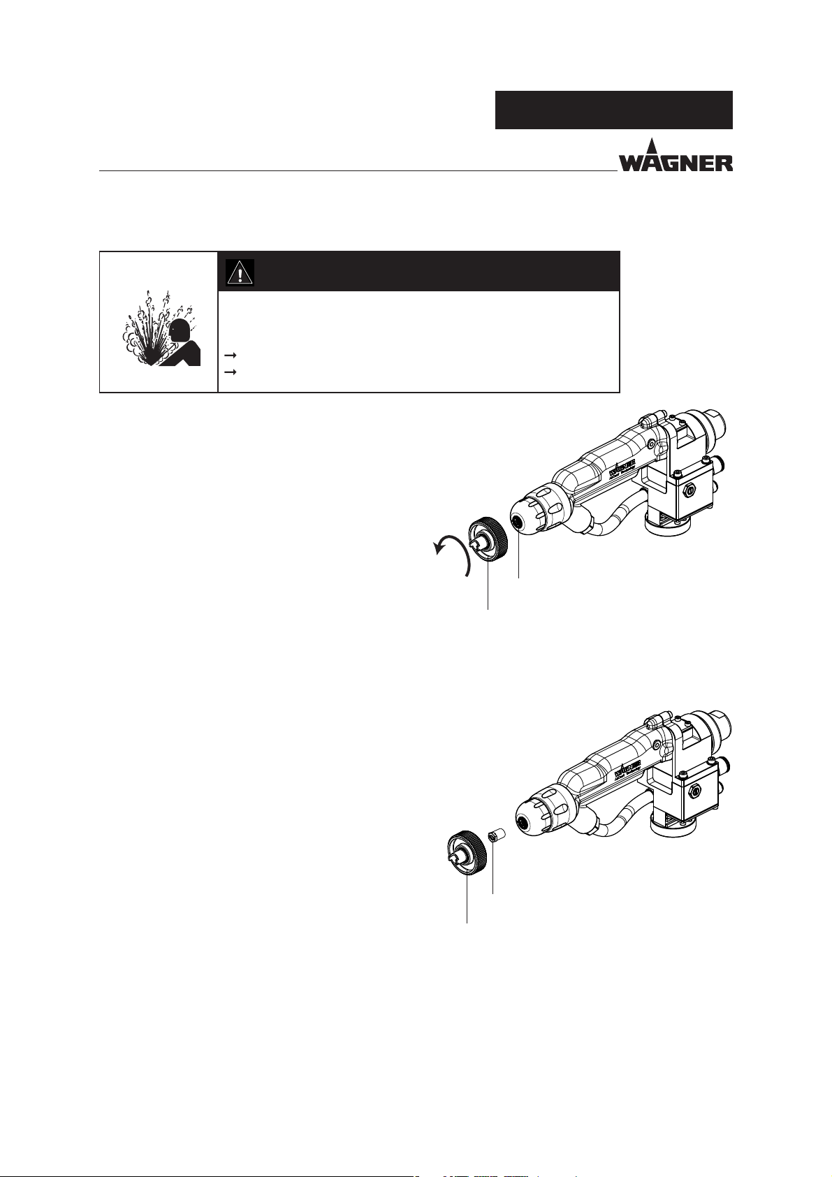
7.3.11 CHANGING THE VALVE HOUSING
GA 5000EAC
Relieve pressure prior changing the valve housing.
Use socket or ring spanner (no wrench)
to tighten the valve housing.
SW9
1.8 Nm
1.32 lb ft
Chapter 7.3.3
B_06426
58
Page 59
VERSION 09/2016 ORDER NUMBER DOC2360922
OPERATING MANUAL
GA 5000EAC
8 CLEANING AND MAINTENANCE
8.1 CLEANING
8.1.1 CLEANING STAFF
Cleaning work should be undertaken regularly and carefully by quali ed and trained sta .
They should be informed of speci c hazards during their training.
The following hazards may arise during cleaning work:
- Health hazard from inhaling solvent vapors
- Use of unsuitable cleaning tools and aids
8.1.2 SAFETY INSTRUCTIONS
Observe safety instructions in Chapter 4.
DANGER
Incorrect maintenance/repair!
Danger to life and equipment damage.
Only a WAGNER service center or a suitably trained person may
carry out repairs and replace parts.
Only repair and replace parts that are listed in the "Spare parts"
chapter and that are assigned to the unit.
Before all work on the device and in the event of work interruptions:
- Switch o the energy supply and the compressed air supply.
- Relieve the pressure from the spray gun and device.
- Secure the spray gun against actuation.
Observe the operating and service manual for all work.
59
Page 60

VERSION 09/2016 ORDER NUMBER DOC2360922
OPERATING MANUAL
DANGER
Explosive powder/air mixes!
Danger to life and equipment damage.
Before starting cleaning, rinsing, or other manual work, the high
voltage must be shut down and locked to prevent it from being
switched back on!
The spray gun must be separated from the high-voltage supply
before any cleaning work is started!
Only electrically conductive tanks may be used for cleaning and
ushing agents. Ground the tank.
Which cleaning agent is used to clean the spray gun depends
on which parts of the spray gun have to be cleaned and which
product has to be removed. When cleaning the spray gun, only
use non-polar cleaning agents to prevent conductive residues
on the surface of the spray gun. Should it however, be necessary
to use a polar cleaning agent, all residues of this cleaning agent
have to be removed by using a non-conductive and non-polar
cleaning agent, once the cleaning is nished.
Preference should be given to non- ammable cleaning and
ushing agents.
Only cleaning and ushing agents which contain ingredients
of explosion classes IIA and IIB may be used (maximum ignition
energy 0.24 mJ).
The cleaning and ushing agent's ash point must be at least 15 K
above the ambient temperature.
Ensure that no electric component is cleaned with or immersed
into solvent.
GA 5000EAC
60
Page 61

VERSION 09/2016 ORDER NUMBER DOC2360922
OPERATING MANUAL
GA 5000EAC
8.1.3 CLEANING AND FLUSHING THE DEVICE
The spraying system and the spray gun must be cleaned and ushed daily. The cleaning
and ushing agents used must be compatible with the working material.
WARNING
Incompatibility of cleaning/ ushing agent and working
medium!
Risk of explosion and danger of poisoning by toxic gases.
Examine the compatibility of the cleaning and ushing agents
and working media on the basis of the safety data sheets.
NOTICE
Damage to electrical devices!
Never immerse the spray gun in cleaning agent.
NOTICE
Liquid in air tube!
Functional faults caused by swollen seals.
Discharge current to ground No high voltage.
Always point the spray gun down when cleaning.
Ensure that neither lacquers nor cleaning or ushing agent enters the air duct.
When taking a break from work or when stored for a longer period, the spray gun
should be positioned with the adapter pointing downwards.
61
Page 62

VERSION 09/2016 ORDER NUMBER DOC2360922
GA 5000EAC
OPERATING MANUAL
DANGER
Exploding gas / air mixture!
Danger to life from ying parts and burns.
Never spray into a closed tank.
Ground the tank.
Clean nozzle
1. Switch o control unit.
2. Dismount nozzle and clean separately Chapter 7.3.
Flush spraying system and spray gun
3. Connect spraying system to ushing agent supply in accordance with operating
manual for the product pressure generator.
4. Point the spray gun toward the collection tray and switch it on. Switch o gun as
soon as clean ushing agent emerges.
5. Remove ushing agent supply.
Blowing out the air passages of the spray gun
6. Close pump pressure regulator. Switch on compressed air supply on the control unit,
open air pressure regulator for shaping and atomizing air.
7. Actuate the spray gun without activated high voltage and thoroughly blow out the
air passages.
8. For switching off the shaping and atomizing air press the "Standby" button on the
control unit.
9. Switch o the compressed air supply.
Clean the outside of the spray gun
10. Clean the spray gun body and other components of the spraying system with a
cleaning agent recommended by the lacquer manufacturer and dry with a cloth or
blow gun.
Cleaning the nozzle parts
Eliminating nozzle clogging see Chapter 7.3.10
see Chapter 7.3.9
62
Page 63

VERSION 09/2016 ORDER NUMBER DOC2360922
GA 5000EAC
OPERATING MANUAL
8.2 MAINTENANCE
8.2.1 MAINTENANCE STAFF
Maintenance work should be undertaken regularly and carefully by quali ed and trained
sta . They should be informed of speci c hazards during their training.
The following hazards may arise during maintenance work:
- Health hazard from inhaling solvent vapors
- Use of unsuitable tools and aids
An authorized person must ensure that the device is checked for being in a reliable state
after maintenance work is completed.
8.2.2 SAFETY INSTRUCTIONS
Observe the safety instructions in Chapter 4 and Chapter 8.1.2.
Prior to maintenance
- Flush and clean the system
After maintenance
- Carry out a safety checks in accordance with Chapter 8.2.3.
- Put the system into operation (Chapter 6.6) and check for leaks.
- Carry out a function test, if required, in accordance with Chapter 11.
In accordance with the guideline for liquid ejection devices (DGUV regulation 100-500):
- The liquid ejection devices should be checked by an expert (e.g., WAGNER service
technician) for their safe working conditions as required and at least every 12 months.
- For shut down devices, the examination can be suspended until the next start-up.
Chapter 8.1.3.
DANGER
Incorrect maintenance/repair!
Danger to life and equipment damage.
Repair or replacement of devices or parts of devices are only
allowed to be performed outside the hazard area by quali ed
personnel.
63
Page 64

VERSION 09/2016 ORDER NUMBER DOC2360922
OPERATING MANUAL
DANGER
Incorrect maintenance/repair!
Danger to life and equipment damage.
Only a WAGNER service center or a suitably trained person may
carry out repairs and replace parts.
Only repair and replace parts that are listed in the "Spare parts"
chapter and that are assigned to the unit.
Before all work on the device and in the event of work interruptions:
- Switch o the energy supply and the compressed air supply.
- Relieve the pressure from the spray gun and device.
- Secure the spray gun against actuation.
Observe the operating and service manual for all work.
GA 5000EAC
8.2.3 SAFETY CHECKS
For the safe operation of stationary electrostatic spraying equipment for ammable liquid coating products,
intervals for periodical inspections are de ned as follows:
Inspection point Inspection interval Remarks
Gun cleaning, gun ushing daily Chapter 4.2.4, Chapter 8.1
Hoses, tubes, couplings daily Chapter 8.2.4
Grounding weekly Chapter 4.2.2, Chapter 6.4.7
Inspection for damage weekly Chapter 8.1.3, 8.2, 10
Locking of the technical ventilation with the
electrostatic spraying equipment
The above recommended intervals are maximum values and may be modi ed by the operator depending on
the local and operational conditions and the contamination.
Damaged devices must be decommissioned and repaired immediately.
annually Chapter 6.4.4
64
Page 65

VERSION 09/2016 ORDER NUMBER DOC2360922
OPERATING MANUAL
8.2.4 PRODUCT HOSES, TUBES AND COUPLINGS
DANGER
Bursting hose, bursting threaded joints!
Danger to life from injection of product and from ying parts.
Ensure that the hose material is chemically resistant to the
sprayed products and the used ushing agents.
Ensure that the spray gun, threaded joints, and product hose
between the device and the spray gun are suitable for the
generated pressure.
Ensure that the following information can be seen on the hose:
- Manufacturer
- Permissible operating pressure
- Date of manufacture
GA 5000EAC
The service life of the complete hoses between product pressure generator and application
device is reduced due to environmental in uences even when handled correctly.
Check hoses, pipes, and couplings every day and replace if necessary.
Before every commissioning, check all connections for leaks.
Additionally, the operator must regularly check the complete hoses for wear and tear
as well as for damage at intervals that he/she has set. Records of these checks must
be kept.
Undamaged complete hoses are to be replaced when one of the two following
intervals has been exceeded:
– 6 years from the date of the hose crimping (see tting embossing).
– 10 years from the date of the hose imprinting.
Fitting
embossing
(if present)
xxx bar Pressure
yymm
XX Internal code
Meaning
Crimping date
(year/month)
Hose imprinting Meaning
WAGNER Name/Manufacturer
yymm
xxx bar (xx MPa)
e.g., 270 bar (27 MPa)
XX Internal code
DNxx (e.g., DN10) Nominal diameter
Date of manufacture
(year/month)
Pressure
65
Page 66

VERSION 09/2016 ORDER NUMBER DOC2360922
GA 5000EAC
OPERATING MANUAL
9 TROUBLE SHOOTING AND RECTIFICATION
Functional fault Cause Remedy
Insu cient product output Nozzle too small Select larger nozzle
(see "Accessories" chapter).
Product pressure too low Increase product pressure.
Product pressure generator blocked Clean or replace lter.
Nozzle is clogged Clean or replace nozzle.
Poor spray pattern Wrongly adjusted atomizing air Readjust the atomizing air.
Unfavorable nozzle size Select a di erent nozzle (see
"Accessories" chapter).
Product pressure too high/too low Adapt product pressure.
Spray product viscosity too high Thin product in accordance with the
manufacturer's instructions.
Damaged nozzle Attach new nozzle.
Poor wrap-around Poor grounding at object Check grounding of object or hanger
with ohmmeter.
Lacquer resistance too high/too low Check paint resistance (see Chapter 2.5)
Spraying pressure too high Readjust spraying pressure.
No wrap-around No high voltage Switch on high voltage at the control
unit. / Repair malfunction as explained
in the control unit operating manuals.
Connect gun and gun cable/check for
defect.
Check paint resistance (see Chapter 2.5)
Seal in end piece defective Repair by WAGNER Service Department.
Air-passages damp Clean and dry air passages.
Back-spray Poor grounding at object Check grounding.
Distance between spray gun and
object too large
High voltage set wrongly (too high) Adapt high voltage to product.
Loosen the nozzle union nut for
round jet method
Valve seat leaks Valve seat or valve tip worn Replace valve seat or valve tip.
Reduce distance between spray gun
and work piece.
Tighten union nut by hand.
66
Page 67

VERSION 09/2016 ORDER NUMBER DOC2360922
GA 5000EAC
OPERATING MANUAL
10 REPAIR WORK
10.1 REPAIR STAFF
Repair work should be undertaken carefully by quali ed and trained personnel.
They should be informed of speci c hazards during their training.
The following hazards may arise during repair work:
- Health hazard from inhaling solvent vapors
- Use of unsuitable tools and aids
A skilled person must check to ensure that the device is in a reliable state after it is repaired.
Carry out function test in accordance with Chapter 11.
10.2 SAFETY INSTRUCTIONS
Observe the safety instructions in Chapter 4 and Chapter 8.1.2.
Before a Repair
- Flush and clean the system Chapter 8.1.3.
After a Repair
- Carry out a safety checks in accordance with Chapter 8.2.3.
- Put the system into operation (Chapter 6.7) and check for leaks.
- Function test in accordance with Chapter 11.
In accordance with the guideline for liquid ejection devices (DGUV regulation 100-500):
- The liquid ejection devices should be checked by an expert (e.g., WAGNER service
technician) for their safe working conditions as required and at least every 12 months.
- For shut down devices, the examination can be suspended until the next start-up.
DANGER
Incorrect maintenance/repair!
Danger to life and equipment damage.
Only a WAGNER service center or a suitably trained person may
carry out repairs and replace parts.
Only repair and replace parts that are listed in the "Spare parts"
chapter and that are assigned to the unit.
Before all work on the device and in the event of work interruptions:
- Switch o the energy supply and the compressed air supply.
- Relieve the pressure from the spray gun and device.
- Secure the spray gun against actuation.
Observe the operating and service manual for all work.
67
Page 68

VERSION 09/2016 ORDER NUMBER DOC2360922
OPERATING MANUAL
10.3 SPRAY GUN
Plastic parts
Gently handle all plastic parts.
10.3.1 TOOLS
For disassembling and assembling the spray gun, the following tools are required:
- Allen wrench, SW 3
- Wrench, SW 5
- Wrench, SW 7
- Wrench, SW 8
- Wrench, SW 19
- Wrench, SW 22
- Ring spanner, SW 9
- Slide gauge
- Valve needle assembly tool, Order No. 2309368
- Clamping screw assembly tool, Order No. 2325263
GA 5000EAC
Brand notice:
The brands speci ed in this document are property of the respective owners. Loctite®, for
example, is a registered brand of Henkel.
68
Page 69

VERSION 09/2016 ORDER NUMBER DOC2360922
OPERATING MANUAL
10.3.2 DISMANTLING OF THE SPRAY GUN
1
B_05779
GA 5000EAC
2
2.
B_05780
1.
69
Page 70

VERSION 09/2016 ORDER NUMBER DOC2360922
OPERATING MANUAL
3
GA 5000EAC
SW3
SW22
SW19
Product hose:
Do not tilt, but pull it straight out in direction indicated by arrow. At the same time, execute
slight rotational movements.
Fitting (25), if tting has any leaks:
If the tting (25) does not come out with the product hose, it must be removed from the
gun adapter as follows:
- Screw the wood screw (
max. 6 mm deep.
- Pull out straight with suitable pliers. Possibly rotate clockwise simultaneously.
- Thereafter, the tting must be replaced.
If the tting is broken in the gun adapter, WAGNER Service Department must be contacted.
3 mm; 0.12 inches, length 40 mm; 1.6 inches) into the tting (25),
B_05781
SW19
25
4
B_05782
70
Page 71

VERSION 09/2016 ORDER NUMBER DOC2360922
OPERATING MANUAL
5
SW7
SW8
GA 5000EAC
B_05783
Unscrew the collet chuck:
When unscrewing the collet chuck, a
second size 7 wrench must be used for
bracing.
6
Carefully release the cascade
without pliers
SW3
B_05784
71
Page 72

VERSION 09/2016 ORDER NUMBER DOC2360922
OPERATING MANUAL
GA 5000EAC
7
Clamping screw
assembly tool,
Order No. 2325263
Valve needle assembly tool,
Order No. 2309368
27
B_04786
SW9
Valve housing: Use an assembly tool or socket or ring spanner
(not a wrench).
Valve tip (27)
Loosen valve tip by hand using the valve needle assembly tool
(Order No. 2309368).
8
The gold contact sleeve (10) remains in adapter (11) or
sits on resistance (12). Do not lose!
(The other gold contact sleeve is in the contacting (13)).
10
11
12
13
o
n
9
Do not pull out on contact wire.
O-ring (8):
1. Use screwdriver no. 1 to
press under the O-ring.
2. Lever up the O-ring and
remove it.
8
Air manifold ring (9):
1. Locate the start of the thread for recessed internal threading.
2. Lever under the air distribution ring directly in front of the start of the
thread using screwdriver no. 1.
3. As soon as the ring disengages, carefully undo it on all sides.
B_04377
o
n
p
72
Page 73

VERSION 09/2016 ORDER NUMBER DOC2360922
OPERATING MANUAL
10
B_05785
1
9
5
SW5
GA 5000EAC
1. Loosen clamping screw (1) with
assembly tool (5).
2. Remove valve rod unit (2, 3, 4, 6).
3. Only as required:
Remove rod seal (10).
Do not damage the housing in
the process.
3
4
SW7
SW7
SW8
2
6
7
73
Page 74

VERSION 09/2016 ORDER NUMBER DOC2360922
OPERATING MANUAL
10.3.3 CLEANING THE PARTS AFTER DISASSEMBLY
ATTENTION
Please note:
All reusable parts (except for the parts conducting high voltage such as cascade,
adapter, plug compl. etc.) should be cleaned thoroughly using a suitable cleaning
agent.
The adapter, plug and all dismantled parts must be clean and dry after cleaning.
Care should be taken that these parts remain free of solvents, grease or sweat from
the hands (salt water). Clean and mount wearing gloves.
Spare parts may have safety-relevant properties.
Only repair and replace parts that are listed in the "Spare parts" chapter and that are
assigned to the unit.
Defective parts, O-rings and seal sets must always be re-placed.
GA 5000EAC
WARNING
Incompatibility of cleaning agent and working medium!
Risk of explosion and danger of poisoning by toxic gases.
Examine the compatibility of the cleaning agents and working
media on the basis of the safety data sheets.
In Chapter 14 the part numbers for gun spare parts can be found as well as for wearing
parts such as seals.
74
Page 75

VERSION 09/2016 ORDER NUMBER DOC2360922
OPERATING MANUAL
10.3.4 ASSEMBLING THE SPRAY GUN
Assembly aids:
Pos Order No. Description
2 * 9992698 Vaseline white, PHHV II
4 9992511 Loctite® 243
* Use Vaseline sparingly
Valve rod unit:
1
Set length adjusting measure X with collet chuck (6)
and lock with a hexagon nut (2).
GA 5000EAC
2Nm; 1.48 lbft
3
2
2
2
Coat the hollow section with a brush.
Note: avoid the pin and hexagon.
B_05786
4
2
(sparingly)
B_06042
X = 130 ±0.1 mm
X = 5.12 ±0.004 inch
SW7
SW7
6
2
75
Page 76
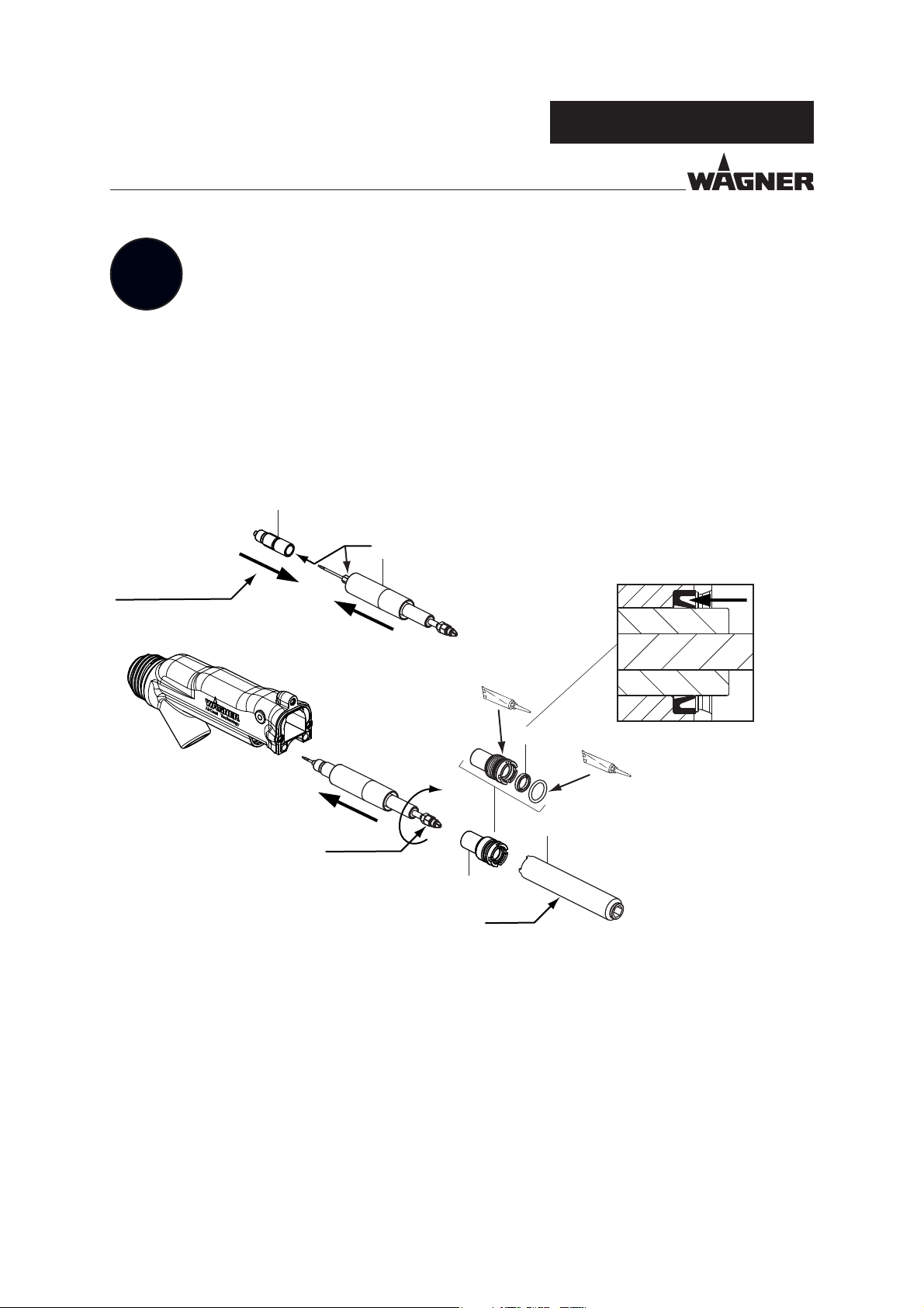
VERSION 09/2016 ORDER NUMBER DOC2360922
OPERATING MANUAL
GA 5000EAC
2
Wear gloves!
The outside thread of the packing (3) must be free of lacquer.
Valve rod unit (4) and packing (3):
- grease,
- slide together,
- screw together
Grease clamping screw (1) and mount using assembly tool (5).
0.8 Nm + 0.1 Nm;
0.6 + 0.07 lbft
3
SW5
4
2
Only as required (if the rod seal was
removed): Press in rod seal (10). In the
process, press only on the lowest area
of the rod seal.
B_05787
SW7
0.4 - 0.5 Nm
0.3 - 0.37 lb ft
1
0.5 Nm
0.37 lb ft
10
2
5
76
Page 77

VERSION 09/2016 ORDER NUMBER DOC2360922
OPERATING MANUAL
Gold contact sleeve (10)
Check whether the gold contact sleeve is
located in the end piece (11). Otherwise,
insert the sleeve onto the resistance (12).
GA 5000EAC
Ensure the correct
insertion position and
installation direction.
3
Valve needle assembly tool,
Order No. 2309368
10
11
12
Ensure the correct
insertion position.
(1)
(4)
B_04379
4
2
3
0.1 Nm; 0.07 lb ft
SW9
1.8 Nm; 1.33 lb ft
Clamping screw assembly tool,
Order No. 2325263
B_04793
1. Move the valve rod to the rear position
so that the sealing area does not become
scratched (1).
2. Slightly tighten AC valve tip (2) by hand
(3 ngers) using an assembly tool.
3. Use socket or ring spanner (no wrench) to
tighten the valve housing (3).
4. Slide the valve rod to the forward position
(at the valve seat) (4).
77
Page 78

VERSION 09/2016 ORDER NUMBER DOC2360922
OPERATING MANUAL
GA 5000EAC
5
2
B_05788
Clean and degrease the inside of the adapter
and the outside of the cascade, then grease
the cascade surface with Vaseline.
4
SW3
0.8 Nm; 0.6 lb ft
B_06083
1.3±0.1mm
A
Set dimension 1.3 mm:
Via setting the dimension, soiling of air
cap will be decreased.
78
Page 79

VERSION 09/2016 ORDER NUMBER DOC2360922
OPERATING MANUAL
6
SW7
SW8
GA 5000EAC
B_05783
Assembling the collet chuck:
When assembling the collet chuck, a
second size 7 wrench must be used for
bracing.
7
SW26
10 Nm;
7.37 lb ft
B_05789
79
Page 80

VERSION 09/2016 ORDER NUMBER DOC2360922
OPERATING MANUAL
GA 5000EAC
8
SW3
5 Nm;
3.69 lb ft
SW19
10 Nm;
7.37 lb ft
4
2
SW19
2.5 Nm;
1.84 lb ft
SW22
5
B_05790
Fitting (25)
Before assembling the product hose, check
that no tting (25) is in the gun adapter!
Check the tting for damage and replace
if necessary (Order No. 2338853).
25
9
1.
B_05791
2.
80
Page 81

VERSION 09/2016 ORDER NUMBER DOC2360922
OPERATING MANUAL
Flat jet nozzle
10
Round jet nozzle
Assembly, see Chapter 14.4.2
Diverse nozzle sizes, see Chapter 13.1
Assembly, see Chapter 14.4.1
Diverse nozzle sizes, see Chapter 13.2
GA 5000EAC
B_05792
81
Page 82

VERSION 09/2016 ORDER NUMBER DOC2360922
GA 5000EAC
OPERATING MANUAL
11 FUNCTION TEST AFTER THE REPAIR
After all repairs, the device must be checked for safe condition before recommissioning.
The necessary scope of inspection and testing depends on the repair carried out and must
be documented by the repair sta .
11.1 CHECKING THE HIGH VOLTAGE
Necessary test equipment:
EPG 5000 control unit and HV 200 high-voltage tester.
High-voltage measurement on spraying gun.
Connect gun cable to control unit. Mount spray gun to grounded gun mounting.
Switch on the control unit.
The high voltage should be 60 to 65 kV in dry ambient air. The value can be checked with
the display on the control unit (EPG 5000).
Note:
The gun must be clean and dry and must not have any paint or cleaning agent residues.
In the case of ambient air with a high air humidity, the measured value can reduce to
50 to 55 kV.
High-voltage measurement with high-voltage tester
Place the ball of the high-voltage tester on the gun electrode and turn on the high voltage.
The measured value should be 70 to 80 kV.
Notes:
- When measuring the high voltage the measuring device should be held at arms length
as far from the body as possible.
- There should be no chargeable objects within a radius of 1 m; 3.28 ft of the place where
the measurements are taken.
- The placing of the measuring ball of the high-voltage measuring device reduces the
spraying of the high-voltage electrode. As a result the high-voltage value increases
compared to the spraying in the free space.
82
Page 83

VERSION 09/2016 ORDER NUMBER DOC2360922
OPERATING MANUAL
Disruptive discharge test
Check the gun against ground with the grounding rod. No sparks should be formed.
Note: in the vicinity of the electrode harmless corona discharges can occur.
Grounding rod
Order No. 175519
GA 5000EAC
B_06049
83
Page 84

VERSION 09/2016 ORDER NUMBER DOC2360922
OPERATING MANUAL
GA 5000EAC
11.2 AIR TEST
GA 5000EAC
Switch o the atomizing and shaping air, switch on control air.
1. 0.4MPa; 4bar; 58psi: The air valve must switch on correctly.
2. 0.8MPa; 8bar; 116psi: Test for air seal.
3. Switch o control air: The air valve must switch o correctly.
11.3 PRODUCT PRESSURE TEST
Connect high-pressure hose to the spray gun.
Test the seal of the spray gun with suitable medium (e.g., ushing agent or Marcol 52) and
a maximum pressure of 25 MPa; 250 bar; 3626 psi. Increase the pressure gradually while
doing so.
Observe the following gun components:
Product connection, nozzle body, product valve (no post-spraying).
DANGER
Exploding gas / air mixture!
Danger to life from ying parts and burns.
Never spray into a closed tank.
Ground the tank.
11.4 TEST OF SPRAY PATTERN
Check spray pattern in accordance with Chapter 7.3.1
84
Page 85

VERSION 09/2016 ORDER NUMBER DOC2360922
OPERATING MANUAL
GA 5000EAC
12 DISPOSAL
NOTICE
Do not dispose of used electrical equipment with household
refuse!
In accordance with European Directive 2002/96/EC on the disposal
of used electrical equipment and its implementation in national
law, this product may not be disposed of with the household refuse,
but must be recycled in an environmentally correct manner.
WAGNER or one of our dealers will take back your used WAGNER
electric or electronic equipment and will dispose of it for you in an
environmentally-friendly way. Please contact one of our service
points, one of our representatives or us directly to arrange this.
Consumable products
Consumable products (lacquers, adhesives, ushing and cleaning agents) must be disposed
of in accordance with all applicable legal requirements.
85
Page 86

VERSION 09/2016 ORDER NUMBER DOC2360922
GA 5000EAC
OPERATING MANUAL
13 ACCESSORIES
13.1 ROUND JET NOZZLES
13.1.1 ACR 5000 ROUND JET NOZZLE ATTACHMENT
Order No. Designation
2309883 ACR 5000 round jet nozzle attachment
(with nozzle spanner, without AC round jet nozzle insert)
13.1.2 AIRCOAT ROUND JET NOZZLE INSERTS
The round jet nozzles are especially suitable for spraying delicate parts, tubes, pro les and
complex work pieces.
Order No. Marking Jet width Recommended edge lter
mm; inch
132720 11 approx. 250; 10 yellow
132721 12 approx. 250; 10 200 mesh
132722 13 approx. 250; 10
132723 14 approx. 250; 10
132724 * 15 approx. 250; 10
132725 16 approx. 250; 10 black
132726 17 approx. 250; 10 100 mesh
132727 18 approx. 250; 10
132728 19 approx. 250; 10
132729 20 approx. 250; 10 white
132730 21 approx. 250; 10 60 mesh
132731 22 approx. 250; 10
* Standard version
Jet width in mm; inches at a distance of 30 cm; 11.8 inches from the object and at a pressure
of 10 MPa; 100 bar; 1450 psi.
B_03210
"?
13.2 FLAT JET NOZZLES
13.2.1 ACF 5000 AIR CAPS FLAT JET
Order No. Designation
2309882 Air cap ACF 5000 - LV suitable for low viscosity products (marked red).
2314203 ACF 5000 air cap - HV suitable for high viscosity products (marked blue).
B_03454
B_03209
86
Page 87

VERSION 09/2016 ORDER NUMBER DOC2360922
OPERATING MANUAL
13.2.2 ACF5000 AIRCOAT FLAT JET NOZZLES
GA 5000EAC
Order No.
395107 07/10 0.18; 0.007 10° Natural lacquer
395207 07/20 20°
395407 07/40 40°
395109 09/10 0.23; 0.009 10° Clear lacquer
395209 09/20 20° Oils
395309 09/30 30°
395409 09/40 40°
395509 09/50 50°
395609 09/60 60°
395111 11/10 0.28; 0.011 10° Synthetic resin lacquer
395211 11/20 20° PVC lacquer
395311 11/30 30°
395411 11/40 40°
395511 11/50 50°
395611 11/60 60°
395811 11/80 80°
395113 13/10 0.33; 0.013 10° Lacquers
395213 13/20 20° Base coat
395313 13/30 30° Primer
395413 13/40 40° Filler
395513 13/50 50°
395613 13/60 60°
395813 13/80 80°
395115 15/10 0.38; 0.015 10° Filler
395215 15/20 20° Rust proo ng paints
395315 15/30 30°
395415 15/40 40°
395515 15/50 50°
395615 15/60 60°
395815 15/80 80°
395217 17/20 0.43; 0.017 20° Rust proo ng paints
395317 17/30 30° Latex paints
395417 17/40 40°
395517 17/50 50°
395617 17/60 60°
395817 17/80 80°
Marking
Drilled hole
mm; inch
Application
Spray angle
B_03163
87
Page 88

VERSION 09/2016 ORDER NUMBER DOC2360922
OPERATING MANUAL
GA 5000EAC
Order No.
395219 19/20 0.48; 0.019 20° Rust proo ng paints
395319 19/30 30° Latex paints
395419 19/40 40°
395519 19/50 50°
395619 19/60 60°
395819 19/80 80°
395221 21/20 0.53; 0.021 20° Mica paints
395421 21/40 40° Zinc rich paints
395521 21/50 50° Rust proo ng paints
395621 21/60 60° Glue paints
395821 21/80 80°
395423 23/40 0.58; 0.023 40°
395623 23/60 60°
395823 23/80 80°
395425 25/40 0.64; 0.025 40°
395625 25/60 60°
395825 25/80 80°
395427 27/40 0.69; 0.027 40°
395627 27/60 60°
395827 27/80 80°
395429 29/40 0.75; 0.029 40°
395629 29/60 60°
395829 29/80 80°
395431 31/40 0.79; 0.031 40°
395631 31/60 60°
395831 31/80 80°
395435 35/40 0.90; 0.035 40°
395635 35/60 60°
395835 35/80 80°
Marking
mm; inch
Drilled hole
Application
Spray angle
B_03163
88
Page 89

VERSION 09/2016 ORDER NUMBER DOC2360922
OPERATING MANUAL
13.3 FILTER
Order No. Designation
3204604 Edge lter, 60 mesh (white)
3204605 Edge lter, 100 mesh (black)
9999002 Edge lter, 200 mesh (yellow)
13.4 ELECTRIC CABLES AND HOSES
13.4.1 GUN CABLE
Order No. Designation
2339157 Gun cable, 10 m; 32.8 ft
GA 5000EAC
B_00019
239158 Gun cable, 15 m; 49.2 ft
2339159 Gun cable, 20 m; 65.6 ft
2339160 Gun cable, 25 m; 82.0 ft
13.4.2 EXTENSION CABLE FOR GUN CABLE
Order No. Designation
2339161 Extension cable, 10 m; 32.8 ft
2339162 Extension cable, 20 m; 65.6 ft
B_03218
B_03218
89
Page 90

VERSION 09/2016 ORDER NUMBER DOC2360922
OPERATING MANUAL
13.4.3 PRODUCT HOSES, STANDARD
Order No. Designation
9984573 High-pressure hose-DN4-PN270-¼"NPS-7.5 m-PA
2302374 High-pressure hose DN4-PN270-¼"NPS-10.0m-PA
GA 5000EAC
9984573-15 High-pressure hose-DN4-PN270-¼"NPS-15.0 m-PA
9984573-20 High-pressure hose-DN4-PN270-¼"NPS-20.0 m-PA
13.4.4 PRODUCT HOSES, LOWR
Order No. Designation
2367212 Product hose, GA EAC LowR 7.5 m
2367213 Product hose, GA EAC LowR 10 m
2367214 Product hose, GA EAC LowR 15 m
2367215 Product hose, GA EAC LowR 20 m
B_06421
B_06031
13.4.5 PRODUCT HOSE, 1.5 MM
Order No. Designation
2367217 Product hose (ID = 1.5 mm)
B_06036
90
Page 91

VERSION 09/2016 ORDER NUMBER DOC2360922
OPERATING MANUAL
13.4.6 AIR HOSES
Order No. Designation
9982035 Air hose, red 6 mm, per meter
9982077 Air hose, green 8 mm, per meter
9987095 Air hose, blue 10 mm, per meter
GA 5000EAC
91
Page 92
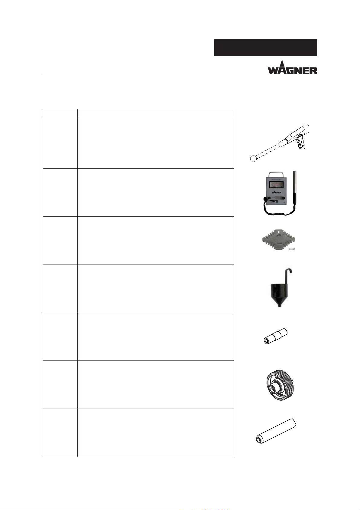
VERSION 09/2016 ORDER NUMBER DOC2360922
OPERATING MANUAL
13.5 MISCELLANEOUS
Order No. Designation
259010 High-voltage tester, HV 200 N
2326041 Paint resistance meter
GA 5000EAC
P_00265
B_03692
999080 Wet lm thickness gauge
50342 Viscosity cup, DIN 4 mm; 0.16 inches
2309368 Valve needle assembly tool
128901 Nozzle spanner, ACR
B_03224
B_03451
"?
2325263 Clamping screw assembly tool
B_03681
92
Page 93

VERSION 09/2016 ORDER NUMBER DOC2360922
OPERATING MANUAL
Order No. Designation
380941 Standard gun holder, 180 mm; Ø 16 mm, 7.1 inches; Ø 0.63 inches
2314079 Ce a adapter plate
380942 Rotary gun holder (standard)
GA 5000EAC
"?
B_03099
380945 Rotary holder, 40/40/5
380943 Complete swivel drive
380944 Cross clamp for swivel drive
2370869 Robot connection, GA 5000
"?
"?
"?
B_06075
B_06076
93
Page 94

VERSION 09/2016 ORDER NUMBER DOC2360922
GA 5000EAC
OPERATING MANUAL
14 SPARE PARTS
14.1 HOW CAN SPARE PARTS BE ORDERED?
Always supply the following information to ensure delivery of the right spare part:
Order number, designation and quantity
The quantity need not be the same as the number given in the quantity column "Stk" on
the list. This number merely indicates how many of the respective parts are used in each
component.
The following information is also required to ensure smooth processing of your order:
Address for the invoice
Address for delivery
Name of the person to be contacted in the event of any queries
Type of delivery (normal mail, express delivery, air freight, courier, etc.)
Identi cation in spare parts lists.
Explanation of column "K" (labeling) in the following spare parts lists:
Wearing parts
Note: These parts are not covered by warranty terms.
Not part of standard equipment, available, however, as additional extra.
DANGER
Incorrect maintenance/repair!
Danger to life and equipment damage.
Only a WAGNER service center or a suitably trained person may
carry out repairs and replace parts.
Only repair and replace parts that are listed in the "Spare parts"
chapter and that are assigned to the unit.
Before all work on the device and in the event of work interruptions:
- Switch o the energy supply and the compressed air supply.
- Relieve the pressure from the spray gun and device.
- Secure the spray gun against actuation.
Observe the operating and service manual for all work.
94
Page 95

VERSION 09/2016 ORDER NUMBER DOC2360922
OPERATING MANUAL
14.2 GA 5000EACIC SPRAY GUN
Spare parts list for GA 5000EACIC
Pos K Stk Order No. Designation
1 1 2360898 GA 5000EACIC
2 1 2315775 Union nut AC, complete
31-
4 1 2307232 Adapter seal
= Wearing part
Adapter, complete GA 5000EAC
(For details, see Chapter 14.2.1)
GA 5000EAC
95
Page 96

VERSION 09/2016 ORDER NUMBER DOC2360922
OPERATING MANUAL
43
2
50
GA 5000EAC
44
SW3
5 Nm;
3.68 lb ft
32
33
3
4
1
15
50
SW14
12 Nm;
8.85 lb ft
16
8
9
10
17 18
45
22
19
11
13
14
5
6
7
12
30
22
34
35
36
23
22
27
24 25
21
20
37
31
SW2.5
0.6 Nm;
0.44 lb ft
38
29
28
26
SW2.5
0.6 Nm;
0.44 lb ft
39
50
40
SW14
12 Nm;
8.85 lb ft
50
41
42
50
B_06039
50
20
SW4
7 Nm;
5.16 lb ft
96
Page 97

VERSION 09/2016 ORDER NUMBER DOC2360922
OPERATING MANUAL
Spare parts list for GA 5000EACIC
Pos K Stk Order No. Designation
5 2 9930128 Parallel pin
6
7 1 2360689 Seal
8 1 2360813 Cable, complete
9 1 2357712 Locknut
10 1 2307739 Mounting nut
11
12 1 2307868 Round spray jet reduction
13
14 1 2357739 Cover
15 1 2386373 Product hose, complete GA AC
16
17 2 9900353 Hexagon socket cylinder head screw
18 1 3204605 Edge lter, 100 mesh
19 1 2308764 Filter socket AC
20 2 9900329 Hexagon socket cylinder head screw
21
22 9 9906029 Hexagon socket cylinder head screw
23 1 9998090 Straight screw-in tting
24 1 9998987 Straight threaded tting
25 1 9998770 Coding ring blue, d10
26 1 9998274 Threaded plug, G1/4"
27 1 9998995 Coding ring red, d6
28
29 1 2358895 Sealing plug
30 2 2360690 Plug
31 1 2313501 Complete piston IC
32 7 9900308 Hexagon socket cylinder head screw
33 4 9920104 Washer
34 1 2357167 Lock plate
35 1 2357166 Seal
36 1 2357164 Contact holder
37
38 1 9971025 O-ring
39 1 2371130 Pull rod
40
41 1 9998991 Cylindrical helical spring
42 1 2307741 End cap short
43 1 2365237 Cover, labeled
44 1 2365238 Lid labeled, EACIC
45 1 2338526 Contact spacer
50 1 9992511 Loctite® 243
5 9974265 O-ring
(only for WAGNER Service Department)
1 9971388 O-ring
1 2357738 Seal
1 2338853 Connecting tting AC
1 2357737 Mounting bracket
1 9974089 O-ring
1 248314 O-ring
1 2309945 Cylindrical helical spring
GA 5000EAC
1 2369320 Service set Air/Controller, GA 5000E
= Wearing part
97
Page 98

VERSION 09/2016 ORDER NUMBER DOC2360922
OPERATING MANUAL
14.2.1 GA 5000EAC ADAPTER
2
5
6
3
7
8
4
9
1
GA 5000EAC
10
For setting, see Chapter 10.
19
130±0.1 mm
5.12±0.004 inch
15
16
17
18
11
12
13
14
20
B_06046
98
Page 99
VERSION 09/2016 ORDER NUMBER DOC2360922
OPERATING MANUAL
Spare parts list for adapter
Pos K Stk Order No. Designation
1 1 - Adapter, complete GA 5000EAC
2 1 2312175 Valve housing AC, complete
3 1 2312186 Valve needle AC, complete
4 1 2357170 Adapter, GA 5000EAC
5 1 2313314 Air manifold ring, AC
6
7 1 2314283 Contacting, AC
8 1 9952777 High resistance, bare
9 1 9960808 Socket contact component (gold contact sleeve)
10 1 2312181 Cascade, complete
11 1 2357665 Clamping screw valve rod, complete
12 1 2307062 Clamping screw valve rod
13
14 1 9974166 O-ring
15 1 2369017 Valve rod unit, AC
16 1 9910108 Hexagon nut
17 1 2357740 Collet chuck
18 1 2357741 Tension nut
19 1 2357106 Packing, complete
20 1 2325263 Clamping screw assembly tool
1 2307180 O-ring, sheathed
1 2311562 Rod seal
GA 5000EAC
1 2369015 Service set, GA 5000EAC adapter
= Wearing part
= Included in service set
= Not part of the standard equipment but available as a special accessory.
99
Page 100

VERSION 09/2016 ORDER NUMBER DOC2360922
OPERATING MANUAL
14.3 GA 5000EACEC SPRAY GUN
41
2
50
GA 5000EAC
42
SW3
5 Nm;
3.68 lb ft
30
31
3
4
1
14
50
SW14
12 Nm;
8.85 lb ft
15
8
9
10
11
16 17
5
6
7
44
21
12
13
18
28
21
32
33
34
21
22
20
20
35
29
23 24
SW2.5
0.6 Nm;
0.44 lb ft
36
2627
25
SW2.5
0.6 Nm;
0.44 lb ft
50
37
38
39
40
50
B_06040
50
19
SW4
7 Nm;
5.16 lb ft
100
 Loading...