

Page 1

FINECOAT 9900 PLUS
GB
D
F
I
HVLP SPRAY SYSTEM
owner‘s manual • betriebsanleitung • mode d’emploi •
istruzioni per l’uso • MANUAL DE OPERAÇÕES • instrucciones de uso
wagner-group.com
RFB
0618 • Form No. 0276799B
E
Page 2

original operating manual / contents
FC9900 Plus
GB ________________________________________ 2
D _______________________________________ 16
F _______________________________________ 30
I _______________________________________ 44
RFB _______________________________________ 58
E _______________________________________ 72
1 SAFETY REGULATIONS ___________________ 3
1.1 Explanation of symbols used _____________________3
1.2 Safety hazards ________________________________3
1.3 Electrical safety _______________________________4
2 INTRODUCTION _________________________ 5
2.1 Technical data ________________________________5
3 USING AN HVLP SPRAYER ________________ 6
3.1 Setup _______________________________________6
3.2 Dual ltration system ___________________________ 6
3.3 Filter warning system __________________________6
4 STARTING OPERATION ___________________ 7
4.1 Setting the FC9900 Plus spray gun ________________7
5 SPRAYING TECHNIQUE ___________________ 9
5.1 Breaks in work ________________________________9
6 FINISHING WORK AND CLEANING
THE UNIT ______________________________ 10
7 MAINTENANCE _________________________11
7.1 Cleaning/replacing the lters ___________________11
7.2 Cleaning the air hoses _________________________11
8 CHOOSING A PROJECTOR SET ____________ 12
8.1 Changing a projector set _______________________ 12
9 MATERIAL REDUCTION/PROJECTOR SET
CHART ________________________________ 13
10 REMEDY IN CASE OF FAULTS _____________ 13
10.1 Servicing ____________________________________ 13
11 SPECIAL ACCESSORIES __________________ 14
IMPORTANT NOTES ON PRODUCT LIABILITY ___15
3+2 YEARS GUARANTEE FOR PROFESSIONAL
FINISHING _________________________________ 15
SPARE PARTS LISTS __________________________86
Spare parts list for main assembly _____________________ 86
Spare parts list for turbine assembly ___________________88
Spare parts list for upper housing assembly _____________ 90
Spare parts list for lower housing assembly _____________92
WIRING DIAGRAM ________________________ 94/95
CE DECLARATION OF CONFORMITY ________ 96/97
SALES AND SERVICE COMPANIES _________99/100
2
Page 3

safety regulations
At
i
i
FC9900 Plus
1 SAFETY REGULATIONS
1.1
This manual contains information that must be read and
understood before using the equipment. When you come to
an area that has one of the following symbols, pay particular
attention and make certain to heed the safeguard.
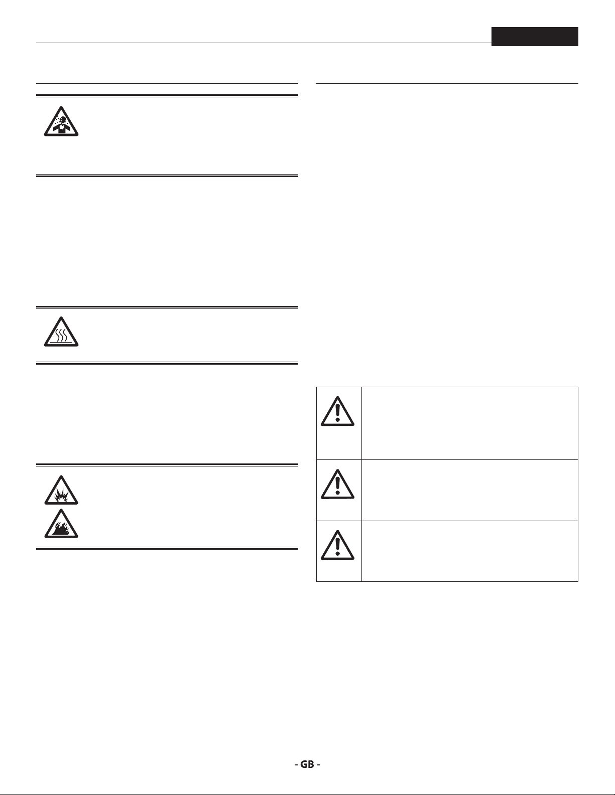
EXPLANATION OF SYMBOLS USED
This symbol indicates a potential hazard
that may cause serious injury or loss of life.
Important safety information will follow.
This symbol indicates a potential hazard
to you or to the equipment. Important
tention
information that tells how to prevent
damage to the equipment or how to avoid
causes of minor injuries will follow.
Danger of skin burn injury
Danger of re from solvent and paint fumes
Danger of explosion from solvent, paint
fumes and incompatible materials
Danger of injury from inhalation of harmful
vapors
1.2 SAFETY HAZARDS
HAZARD: EXPLOSION HAZARD DUE
TO INCOMPATIBLE MATERIALS
Will cause severe injury or property damage.
PREVENTION:
• Do not use materials containing bleach or chlorine.
• Do not use halogenated hydrocarbon solvents such as
methylene chloride and 1,1,1 - trichloroethane. They
are not compatible with aluminum and may cause an
explosion. If you are unsure of a material’s compatibility
with aluminum, contact your coating’s supplier.
A list of the materials used in the construction of
the equipment will be made available on request
to validate compatibility with the coating
materials to be used.
HAZARD: GENERAL
This product can cause severe injury or property
damage.
Ear protection must be worn
Eye protection must be worn
Notes give important information which
should be given special attention.
PREVENTION:
• Read all instructions and safety precautions before
operating equipment.
• Follow all appropriate local, state, and national codes
governing ventilation, re prevention, and operation.
• Use only manufacturer authorized parts. User assumes all
risks and liabilities when using parts that do not meet the
minimum specications and safety devices of the pump
manufacturer.
• Before each use, check all hoses for cuts, leaks, abrasion
or bulging of cover. Check for damage or movement of
couplings. Immediately replace the hose if any of these
conditions exist. Never repair a hose. Replace it with an
identical replacement hose.
• NEVER aim the gun at any part of the body.
• Wear clothing to keep paint o skin and hair.
• Wear ear protection.
• Do not spray outdoors on windy days.
• Never leave this equipment unattended. Keep away from
children or anyone not familiar with the operation of HVLP
equipment.
3
Page 4
safety regulations
can be harmful if inhaled or come in contact with
HAZARD: HAZARDOUS VAPORS
Paints, solvents, insecticides, and other materials
body. Vapors can cause severe nausea, fainting,
or poisoning.
PREVENTION:
• Use a respirator or mask if vapors can be inhaled. Read
all instructions supplied with the mask to be sure it will
provide the necessary protection.
• Wear protective eyewear.
• Wear protective clothing as required by coating
manufacturer.
HAZARD: SKIN BURN INJURY
Heated parts can cause severe skin burn injury.
PREVENTION:
• Quick disconnect ttings on the hose and spray gun become
hot during use. Avoid skin contact with quick disconnect
ttings when they are hot. Allow quick disconnect ttings
to cool before disconnecting the spray gun from the hose.
FC9900 Plus
• Power cord must be connected to a grounded circuit
(electric units only).
• Follow material and solvent manufacturer’s warnings and
instructions. Be familiar with the coating material’s MSDS
sheet and technical information to ensure safe use.
• Use extreme caution when using materials with a ashpoint
below 70° F (21º C). Flashpoint is the temperature that a
uid can produce enough vapors to ignite.
• The object to be coated must be earthed.
• Before working on the device, remove the power plug from
the socket.
1.3 ELECTRIC SAFETY
Electric models must be grounded/earthed. In the event
of an electrical short circuit, grounding/earthing reduces
the risk of electric shock by providing an escape wire for the
electric current. This product is equipped with a cord having
an grounding/earthing wire with an appropriate grounding/
earthing plug. Connection to the power cord only through a
special feed point, e.g. through an error protection insallation
with INF < 30 mA.
DANGER — Work or repairs at the electrical
equipment may only be carried out by a skilled
electrician. No liability is assumed for incorrect
installation. Switch the unit o. Before all repair
work, unplug the power plug from the outlet.
HAZARD: EXPLOSION OR FIRE
Solvent and paint fumes can explode or ignite.
Severe injury and/or property damage can occur.
PREVENTION:
• Provide extensive exhaust and fresh air introduction to
keep the air within the spray area free from accumulation
of ammable vapors.
• Avoid all ignition sources such as static electricity sparks,
electrical appliances, ames, pilot lights, hot objects, and
sparks from connecting and disconnecting power cords or
working light switches.
• Plastic can cause static sparks. Never hang plastic to
enclose spray area. Do not use plastic drop cloths when
spraying ammable materials.
• Do not smoke in spray area.
• Fire extinguisher must be present and in good working
order.
4
Danger of short-circuits caused by water
ingressing into the electrical equipment. Never
spray down the unit with high-pressure or highpressure steam cleaners.
Caution – The power cord for this equipment
acts as an supply circuit connector. The power
cord must be placed near an easily accessible,
unobstructed socket-outlet.
Page 5

introduction
FC9900 Plus
2 INTRODUCTION
This High Volume/Low Pressure (HVLP) spray system is designed
for applying coatings to surfaces that can be sprayed faster
than brushing or rolling and are too small for traditional airless
sprayers. Components of this system include a power switch, a
power cord, a lter warning light, a circuit breaker switch, a dual
ltration system, a cup holder, an air hose, and an air outlet.
The turbine is also equipped with a tool box. It is located on the
reverse side of the turbine and can be used to store projector
sets or any other small spare parts.
1
2
4
3
5
6
7
8
1. Circuit breaker switch
2. Filter warning light
3. Filter
4. Air inlet
5. Cup holder
6. Filter (in the end of can)
7. Power switch
8. Air outlet
* Air hose not pictured.
2.1 TECHNICAL DATA
Voltage 100-110V~, 50/60 Hz or
220V-240V~, 50/60 Hz
Power consumption P1 1836 W
Max. current comsumption
100-110V~
220V-240V~
Max. air ram pressure 0,72 bar (10,5 psi)
Rpm 21 000 rpm
Turbine weight 15 kg
Mains cable 3 m
Container capacity 1 liter
Air hose 9,1 m
Whip hose length 1,5 m
Nozzle set (standard) No. 4 (1.8 mm)
Max. permissible coating
temperature
Typical coating ow rate 0,35 l/min
Max. noise level
turbo-blower 75 dB (A) *
paint spray gun 76 dB (A)
* Measuring location: 1 m in distance from the unit 1.60 m
above the oor, reverberant oor.
** Measuring location: 2.5 m distance from the unit 1.60 m
above the oor.
13,4A
9,0A
43ºC
With this HVLP spray system, you can achieve the highest
quality professional nish possible with little or no preparation
or setup time. Please review all the information contained in
this manual before operating the system.
5
Page 6

using an HVlp spray system
i
i
5
At
i
i
At
3 USING AN HVLP SPRAY SYSTEM
Refer to the following information to operate and
understand your HVLP spray system.
FC9900 Plus
4. Plug the turbine power cord into a grounded receptacle.
5. Turn on the turbine and begin spraying.
Your system may include a short air (“whip”)
hose. The short hose should be connected to the
longer hose or a remote spraying system (sold
separately) and NOT directly to the turbine. See
your spray gun instruction manual for complete
instructions.
1
1. Turbine
2. Air hose
3. Whip hose
4. Coupling
5. Spray gun
Do not attach the short air whip hose directly to
the turbine, as the hose will become damaged.
3.2 DUAL FILTRATION SYSTEM
The turbine has two dierent air lters— one for atomizing air
and one for cooling air. The atomizing air lter (1) is a two-stage,
ne mesh lter designed to trap particles that may damage
your nish. The atomizing air is discharged through the nozzle
of the spray gun where it atomizes the coating material (2). The
cooling air lter (3) is a coarse mesh lter designed to allow
the proper amount of air ow through the turbine for cooling
purposes. Cooling air is exhausted through the cooling air
4
2
3
discharge on the front of the turbine (4).
2
1
3
4
tention
3.3 FILTER WARNING SYSTEM
The lter warning system on your turbine consists of a red lter
3.1 SETUP
Use the following procedure to set up your HVLP
spray system for operation.
Keep the turbine at the maximum possible
distance from the spray area to safeguard against
explosion or re that may be caused by sparking
electrical parts.
1. Prepare your spray gun for operation. Refer to your spray
gun manual for material preparation, setup, and spraying
information.
2. Attach the air hose to the air outlet on the turbine.
3. Attach the air hose to the air inlet on your spray gun.
warning light on the front control panel and an air ow switch
inside the turbine. When the air ow switch does not detect
the appropriate amount of air owing through the turbine, the
lter warning light will come on to indicate that it is time to
clean or change the lters.
The lter warning system does not shut down
the turbine.
Clean lters regularly. Clogged lters can cause
excessive heat and possibly damage the turbine.
tention
6
Page 7

starting operation
i
At
FC9900 Plus
4 STARTING OPERATION
Before connecting to the mains supply make
sure that the mains voltage corresponds to the
operating voltage on the rating plate. The unit
must be connected with a properly earthed
shockproof socket.
1. Screw air hose end (anti-kink spring) onto the turboblower.
Couple air hose to the paint spray gun.
2. Open closing lever on the paint container, remove paint
container.
3. Fill paint container with coating material.
4. Check that the paint container seal is clean and is seated
correctly.
5. Clip the container onto the spray gun and secure with the
closing lever.
6. Switch the turbo-blower on.
7. Point the paint spray gun at the object to be sprayed.
8. Determine the settings for the spray pattern, spray jet
width, amount of material, amount of air and ascending
feed pipe settings, see g. 4 - 10 and the description page
7/8.
9. Operate trigger on the paint spray gun.
4.1 SETTING THE FC9900 PLUS SPRAY GUN
SPRAY PATTERN SELECTION FIG. 4
A = vertical at jet for horizontal surfaces
B = horizontal at jet for vertical surfaces
C = Round jet for corners and edges and places dicult to
access.
ABC
SETTING THE REQUIRED SPRAY PATTERN FIG. 5
Turn the air cap (1) to the required spray pattern position.
tention
Never pull trigger while adjusting the air cap
settings.
1
7
Page 8

starting operation
i
FC9900 Plus
SETTING THE SPRAY JET WIDTH FIG. 6
Adjusting ring
Turn to the right = wider spray jet
Turn to the left = narrower spray jet
The adjusting ring does not fasten the air cap!
SETTING THE AMOUNT OF MATERIAL FIG. 7
Set the amount of material by turning the material adjustment
knob.
Turn to the left = more material
Turn to the right = less material
SETTING THE ASCENDING FEED PIPE
SPRAYING OBJECT LYING ON FLOOR FIG. 9
Turn rotating lever clockwise as far as it will go.
SPRAYING OBJECT OVER HEAD FIG. 10
Turn rotating lever anti-clockwise as far as it will go.
SETTING THE AMOUNT OF AIR FIG. 8
The correct setting for the amount of air is decisive for the
atomization and formation of paint mist.
Maximum
Minimum Minimum
8
Page 9

spraying tecHnique
i
FC9900 Plus
5 SPRAYING TECHNIQUE
Hold the paint spray gun upright and maintain a constant
distance of about 3 - 20 cm to the object being sprayed.
Move the paint spray gun evenly either from side to side or up
and down. If the gun is moved evenly, it will produce an even
surface nish. No runs will occur if the speed is correct.
Always start spraying away from the object and avoid stopping
spraying whilst still on the object.
If the round jet setting is used, the distance may
be increased according to the size of the object
being sprayed.
• In case of excessive paint mist formation, adjust the air and
material ow respectively and alter the distance from the
object.
RIGHT
3 - 20 cm
5.1 BREAKS IN WORK
1. Turn the material regulating knob to the right as far as it
will go (g. 13).
This will secure the paint spray gun against unintentional
operation.
2. Switch the unit o.
WRONG
Excessive paint mist formation, uneven surface nish.
9
Page 10

finisHing work and cleaning tHe unit
i
i
6 FINISHING WORK AND CLEANING THE
UNIT
1. Switch the unit o.
2. Hold the paint spray gun in the original container. Press the
trigger to release the pressure in the spray gun container.
3. Undo the paint container closing lever and remove the
container.
4. Empty the remaining coating material into the original
container.
5. Fill the spray gun container with solvent or water and t
onto the spray gun.
Only use solvents with a ash point above 21 °C.
6. Shake the paint spray gun well.
7. Switch the unit on and spray the solvent or water into an
open container.
FC9900 Plus
Never use sharp metal objects to clean the
nozzles or air channels of the FC9900 Plus spray
gun.
12. Apply a ne coat of silicone-free oil to the marked areas
(g 14).
Never spray into a container with only a small
opening (bunghole)!
8. Repeat this procedure until the solvent or water coming
out of the tip is clear.
Then empty the paint container completely.
Never leave solvents in the spray gun container;
this may cause pressure to build up in the
container.
Always keep the paint container seal clean of left over
coating material and check regularly for signs of damage.
9. Switch the unit o.
10. Clean the outer surfaces of the paint container and paint
spray gun with a cloth soaked in solvent or water.
Do not leave the FineCoat 9900 Plus spray gun
immersed in solvent for extended periods! (The
seals and air pipe on non-return valve may swell,
preventing them from functioning properly.)
13. If the paint spray gun is not used for any length of time, it
should be cleaned and protected by applying a ne coat of
silicone-free oil.
11. Unscrew adjusting ring, remove air cap and spring plate.
Unscrew nozzle. Clean air cap, tip and needle with brush
and solvent or water.
10
Page 11

maintenance
i
At
i
At
i
i
At
FC9900 Plus
7 MAINTENANCE
Use the following procedures to keep your HVLP
spray system running properly.
7.1 CLEANING / REPLACING THE FILTERS
Make sure the turbine is unplugged before
changing the lters.
tention
1. Remove the lter covers (1) on each side of the turbine by
turning them counterclockwise.
1
Do not use highly ammable solvents, such as
lacquer thinner, to clean the lters.
Do not soak paper pleated lter in solvents. Only
tap the lter or use compressed air directed at
tention
3. Clean the lters. Either tap the lters to knock out the
4. Insert each lter back into its corresponding lter can.
5. Replace the lter covers on each side of the turbine by
the inside (the clean side).
contaminants or use pressurized air to blow out the
contaminants. For material that is not blown or knocked
loose easily, soak the lters in soapy water or mineral
spirits. Allow the lters to dry completely before placing
them back in the turbine.
Make sure the white pleated lter is tted securely
to the spokes of the lter can. Turn clockwise to
secure in place.
turning them clockwise.
2. Remove each lter set (pre-lter [2] and lter [3]) from the
lter housing on each side of the turbine.
The white pleated lter (4) is removed from the
turbine in the same manner as the lter cover.
Turn counterclockwise to unlock and remove.
2
3
4
2
After several cleanings, it may become necessary
to replace the lters. Refer to the parts list near
the end of this manual for the lter replacement
kit part number.
7.2 CLEANING THE AIR HOSES
1. Periodically wipe the outer surface of the air hose with a
damp cloth to keep clean.
DO NOT submerge into or ush the air hose with
water or any chemical.
tention
DO NOT use methylethylketon (MEK), naphtha,
mineral spirits, paint thinner, xylol/xylene, or
toluel/toluene to clean the air hose. Exposure
over time could cause damage to the hose.
Store indoors with the cord wrapped around the
handle.
11
Page 12

cHoosing a projector set
i
At
8 CHOOSING A PROJECTOR SET
FC9900 Plus
Your HVLP spray gun should be tted with the
proper projector set for the type of work you
will be performing. A projector set consists of a
needle assembly (Fig. 17, item 1), a uid nozzle
(2), and an air cap (3).
1
2
You should choose a projector set based on two things: the
type of material to be sprayed and the nish desired.
The chart on the following page should help you to make the
right choice.
3
8.1 CHANGING A PROJECTOR SET
3. Remove the material ow adjustment knob (Fig. 19, item
1) and spring (2).
2
1
4. Remove the needle (Fig. 20, item 1).
If the needle does not slide out easily, loosen the
packing nut to prevent the needle or packing
tention
from being damaged.
1. Remove the air cap ring (Fig. 18, item 1), air cap (2), and
spring plate (3).
3
2
1
2. Remove the uid nozzle.
1
5. Install the new projector set in reverse order.
12
Page 13

material reduction/projector set cHart / remedy in case of faults
i
FC9900 Plus
9 MATERIAL REDUCTION/PROJECTOR SET CHART
Before spraying, the material being used must be thinned with an appropriate solvent and the proper projector set must be installed.
It is always best to follow the material manufacturers recommendations and thinning procedures.
There are two simple methods of measuring the proper thickness of a material:
1. Dip a paint stick into the material and remove it, watching carefully as the material runs o. When the material begins to form
drops, the drops should fall about 1 second apart.
2. Use a viscosity cup (P/N 0153165). Dip the cup into the material and remove it. Use a watch or clock to time how long the
material drains from the cup in a continuous stream. Once the continuous stream breaks, stop timing and refer to the table
below. Add the appropriate solvent and continue testing until the proper thickness is reached for the type of material you are
using.
MATERIAL VISCOSITY DINS 4 MM DIN CUP PROJECTOR SET
Solvent-based lacquer paints 15 - 45 3 - 4
Water-soluble lacquer paints observe manufacturer’s instructions 4 - 5
Wood preservatives (scumble, mordants, etc). undiluted 2 - 3
Multi-color eect materials, multi-color paint observe manufacturer’s instructions 6 - 7
Texture and eect paints observe manufacturer’s instructions 5 - 6
10 REMEDY IN CASE OF FAULTS
Type of malfunction
A. Restricted air ow or no air ow
B. Filter warning light is on
C. The turbine has no power
D. Excessive arcing/sparking in the
turbine
The turbine motor can be damaged if not serviced properly. Have the brushes (P/N 0276878) checked for wear by an
authorized service center every 400 hours.
Clean lters regularly. Clogged lters can cause excessive heat and possibly damage the unit.
For additional troubleshooting information, see the manual that came with your gun.
Possible cause
1. Air ow adjustment knob on the spray
gun is turned o
2. Air lters are clogged
1. Air lters are clogged
1. No power at the power supply
2. Circuit breaker has been tripped.
3. Worn turbine brushes
1. Worn turbine brushes
2. Damaged commutator
Measures for eliminating the malfunction
1. Adjust the air ow adjustment knob
2. Clean or replace the lters
1. Clean or replace the lters
1. Check the power supply
2. Reset the breaker. If problem persists, have turbine
inspected at an authorized Wagner service center.
3. Have the brushes replaced at an authorized Wagner
service center
1. Have the brushes replaced at an authorized Wagner
service center
2. Replace the turbine (contact a Wagner service technician)
10.1 SERVICE
Should your spray system need service during the warranty period, return your unit and the proof of purchase to the distributor
where it was purchased. At our option, the unit will be repaired or replaced. In a continued commitment to improve quality, we
reserve the right to make component or design changes when necessary.
13
Page 14

special accessories
11 SPECIAL ACCESSORIES
FC9900 Plus
RN 30 EXTENSION TIP FIG. 22
for ribbed radiators, length 30cm.
Part No. 0261 020
WSL 50 SPRAY LANCE FIG. 23
Area of application
Removating and repair work
For ceilings and walls
Material supply by means of a commercially available pressure
tank.
Part No. 0261 023
WSL 60 SPRAY LANCE FIG. 24
When coating materials can be used?
Coating materials which, due to their properties, cannot be
used with a paint spray gun, e.g., liquid wood chip, multi-color
eect coating, ornamental plaster, texture and spray ller, etc.
Part No. 0261 024
POWER CART
Part No. 0524 001
1.9 L REMOTE PRESSURE TANK FIG. 25
Part No. 0524 230
14
Page 15

FC9900 Plus
IMPORTANT NOTES ON PRODUCT LIABILITY
As a result of an EC regulation being eective as from January 1, 1990, the
manufacturer shall only be liable for his product if all parts come from him or
are released by him, and if the devices are properly mounted and operated.
If the user applies outside accessories and spare parts, the manufacturer´s
liability can fully or partially be inapplicable; in extreme cases usage of the
entire device can be prohibited by the competent authorities (employer´s
liability insurance association and factory inspectorate division).
Only the usage of original WAGNER accessories and spare parts guarantees that
all safety regulations are observed.
3+2 YEARS GUARANTEE FOR PROFESSIONAL FINISHING
Wagner professional guarantee
(Status 01.02.2009)
1. Scope of guarantee
All Wagner professional colour application devices (hereafter referred to as
products) are carefully inspected, tested and are subject to strict checks under
Wagner quality assurance. Wagner exclusively issues extended guarantees to
commercial or professional users (hereafter referred to as “customer”) who
have purchased the product in an authorised specialist shop, and which relate
to the products listed for that customer on the Internet under www.wagnergroup.com/pro-guarantee.
The buyer’s claim for liability for defects from the purchase agreement with the
seller as well as statutory rights are not impaired by this guarantee.
We provide a guarantee in that we decide whether to replace or repair the
product or individual parts, or take the device back and reimburse the purchase
price. The costs for materials and working hours are our responsibility. Replaced
products or parts become our property.
2. Guarantee period and registration
The guarantee period amounts to 36 months. For industrial use or equal wear,
such as shift operations in particular, or in the event of rentals it amounts to 12
months.
Systems driven by petrol or air are also guaranteed for a 12 month period.
The guarantee period begins with the day of delivery by the authorised
specialist shop. The date on the original purchase document is authoritative.
For all products bought in authorised specialist shops from 01.02.2009 the
guarantee period is extended to 24 months providing the buyer of these
devices registers in accordance with the following conditions within 4 weeks of
the day of delivery by the authorised specialist shop.
Registration can be completed on the Internet under www.wagner-group.
com/pro-guarantee. The guarantee certicate is valid as conrmation, as is the
original purchase document that carries the date of the purchase. Registration
is only possible if the buyer is in agreement with having the data being stored
that is entered during registration.
When services are carried out under guarantee the guarantee period for the
product is neither extended nor renewed.
Once the guarantee period has expired, claims made against the guarantee or
from the guarantee can no longer be enforced.
3. Handling
If defects can be seen in the materials, processing or performance of the device
during the guarantee period, guarantee claims must be made immediately, or
at the latest within a period of 2 weeks.
The authorised specialist shop that delivered the device is entitled to accept
guarantee claims. Guarantee claims may also be made to the service centres
named in our operating instructions. The product has to be sent without charge
or presented together with the original purchase document that includes
details of the purchase date and the name of the product. In order to claim
for an extension to the guarantee, the guarantee certicate must be included.
The costs as well as the risk of loss or damage to the product in transit or by the
centre that accepts the guarantee claims or who delivers the repaired product,
are the responsibility of the customer.
4. Exclusion of guarantee
Guarantee claims cannot be considered
- for parts that are subject to wear and tear due to use or other natural
wear and tear, as well as defects in the product that are a result of
natural wear and tear, or wear and tear due to use. This includes in
particular cables, valves, packaging, jets, cylinders, pistons, meanscarrying housing components, lters, pipes, seals, rotors, stators, etc.
Damage due to wear and tear that is caused in particular by sanded
coating materials, such as dispersions, plaster, putty, adhesives, glazes,
quartz foundation.
- in the event of errors in devices that are due to non-compliance with
the operating instructions, unsuitable or unprofessional use, incorrect
assembly and/or commissioning by the buyer or by a third party,
or utilisation other than is intended, abnormal ambient conditions,
unsuitable coating materials, unsuitable operating conditions,
operation with the incorrect mains voltage supply/frequency, overoperation or defective servicing or care and/or cleaning.
- for errors in the device that have been caused by using accessory parts,
additional components or spare parts that are not original Wagner
parts.
- for products to which modications or additions have been carried out.
- for products where the serial number has been removed or is illegible
- for products to which attempts at repairs have been carried out by
unauthorised persons.
- for products with slight deviations from the target properties, which are
negligible with regard to the value and usability of the device.
- for products that have been partially or fully taken apart.
5. Additional regulations.
The above guarantees apply exclusively to products that have been bought
by authorised specialist shops in the EU, CIS, Australia and are used within the
reference country.
If the check shows that the case is not a guarantee case, repairs are carried out
at the expense of the buyer.
The above regulations manage the legal relationship to us concludingly.
Additional claims, in particular for damages and losses of any type, which occur
as a result of the product or its use, are excluded from the product liability act
except with regard to the area of application.
Claims for liability for defects to the specialist trader remain unaected.
German law applies to this guarantee. The contractual language is German. In
the event that the meaning of the German and a foreign text of this guarantee
deviate from one another, the meaning of the German text has priority.
J. Wagner GmbH
Division Professional Finishing
Otto Lilienthal Strasse 18
88677 Markdorf
Federal Republic of Germany
15
Page 16

SPARE PARTS DIAGRAM ERSATZTEILBILD
10
ILLUSTRATION DES PIÈCES DE RECHANGE
GB MAIN ASSEMBLY D HAUPTBAUGRUPPE
F ENSEMBLE PRINCIPAL I ASSEMBLAGGIO PRINCIPALE
RFB CONJUNTO PRINCIPAL E CONJUNTO PRINCIPAL
7
1
FC9900 Plus
10
9
9
# FC9900
Plus
--------
1
--------
2
--------
0524927
3
0524593A
4
0524524
5
0524948A
6
0293395
7
0524523A
8
0524526A
9
0524949A
10
--------
11
2
16
3
4
5
3
14
6
7
8
16
13
16
11
12
Description Benennung Désignation
Upper housing assembly (see separate
listing)
5-Stage turbine assembly, 100V-110V~ (see
separate listing)
5-Stage turbine assembly, 220V-240V~ (see
separate listing)
Sidewall silencer Schalldämpfer Seitenwand Silencieux
Silencer assembly Schalldämpfer-Baugruppe Ensemble silencieux
Sealing foam Dichtungsschaum Mousse d'étanchéité
Filter can Filterbehälter Carters de ltre
Screw Schraube Vis
Filter Filter Filtre
Pre-lter Vorlter Préltre
Filter cover Filterabdeckung Couvercle de ltre
Lower housing assembly (see separate
listing)
Obere Gehäuseeinheit (siehe separates
Verzeichnis)
5-stuge Turbinenanordnung, 100V-110V~
(siehe separates Verzeichnis)
5-stuge Turbinenanordnung, 220V-240V~
(siehe separates Verzeichnis)
Untere Gehäuseeinheit (siehe separates
Verzeichnis)
Ensemble boîtier supérieur (voir la liste
séparée)
Ensemble turbine à 5 étapes, 100V-110V~
(voir la liste séparée)
Ensemble turbine à 5 étapes, 220V-240V~
(voir la liste séparée)
Ensemble boîtier inférieur (voir la liste
séparée)
6
15
86
Page 17

FC9900 Plus
ELENCO DEI RICAMBI DIAGRAMA DE PEÇAS SOBRESSALENTES
CUADRO DE PIEZAS DE RECAMBIO
# FC9900
Plus
858-634
12
0524596
13
0524926
14
0524528A
15
0524594
16
0277337
0153165
0275625
0524405A
0524041
# FC9900
Plus
--------
1
--------
2
--------
0524927
3
0524593A
4
0524524
5
0524948A
6
0293395
7
0524523A
8
0524526A
9
0524949A
10
--------
11
858-634
12
0524596
13
0524926
14
0524528A
15
0524594
16
Description Benennung Désignation
Screw Schraube Vis
Exhaust ring Entlüftungsring Anneau d'échappement
Silencer assembly Schalldämpfer-Baugruppe Ensemble silencieux
Filter Filter Filtre
Foam tape Schaumband Bande de mousse
Air hose (not pictured) Luftschlauch (nicht dargestellt) Tuyau à air (non illustré)
Viscosity cup (not pictured) Viskositätsbecher (nicht dargestellt) Godet de viscosimètre (non illustré)
Quick-disconnect, female (not pictured) Schnellanschlussbuchse (nicht abgebildet) Dégagement rapide, femelle (non illustré)
Air hose, whip (not pictured) Luftschlauch, Schlauchpeitsche (nicht
Spray gun, FC9900 Plus (not pictured) Spritzpistole, FC9900 Plus (nicht dargestellt) Pistolet de pulvérisation, FC9900 Plus (non
Denominazione Descrição Denominación
Assemblaggio del vano di alloggiamento
superiore (vedere l’elenco separato)
Assemblaggio della turbina a 5 stadi,
100V-110V~ (vedere l’elenco separato)
Assemblaggio della turbina a 5 stadi,
220V-240V~ (vedere l’elenco separato)
Silenziatore lato parete Silenciador lateral Silenciador de la pared lateral
Assemblaggio del silenziatore Conjunto do silenciador Conjunto de silenciador
Schiuma sigillante Espuma de vedação Espuma de sellado
Scatola del ltro Lata do ltro Recipiente del ltro
Vite Parafuso Tornillo
Filtro Filtro Filtro
Preltro Pré-ltro Preltro
Coperchio del ltro Tampa do ltro Tapa del ltro
Assemblaggio del vano di alloggiamento
inferiore (vedere l’elenco separato)
Vite Parafuso Tornillo
Anello di spurgo Anel de exaustão Anillo de escape
Assemblaggio del silenziatore Conjunto do silenciador Conjunto de silenciador
Filtro Filtro Filtro
Nastro in schiuma Fita de espuma Cinta de espuma
dargestellt)
Conjunto do compartimento superior
(consulte a lista avulsa)
Conjunto da turbina de 5 estágios,
100V-110V~ (consulte a lista avulsa)
Conjunto da turbina de 5 estágios,
220V-240V~ (consulte a lista avulsa)
Conjunto do compartimento inferior
(consulte a lista avulsa)
Tuyau à air, exible (non illustré)
illustré)
Conjunto de la carcasa superior (consulte la
lista separada)
Conjunto de turbina de 5 etapas,
100V-110V~ (consulte la lista separada)
Conjunto de turbina de 5 etapas,
220V-240V~ (consulte la lista separada)
Conjunto de la carcasa inferior (consulte la
lista separada)
0277337
0153165
0275625
0524405A
0524041
87
Flessibile dell’aria (non incluso
nell’illustrazione)
Coppa di viscosità (non inclusa
nell’illustrazione)
Raccordo a scollegamento rapido, femmina
(non incluso nell’illustrazione)
Flessibile dell’aria, a frusta (non incluso
nell’illustrazione)
Pistola spray, FC9900 Plus (non inclusa
nell’illustrazione)
Mangueira de ar (não exibida) Manguera de aire (no se muestra)
Copo de viscosidade (não exibido) Depósito de viscosidad (no se muestra)
Desconexão rápida, fêmea (não exibida) Desconexión rápida, hembra (no se muestra)
Mangueira de ar, chicote (não exibida) Manguera de aire, conexión exible (no se
Pistola de pulverização, FC9900 Plus (não
exibida)
muestra)
Pistola pulverizadora, FC9900 Plus (no se
muestra)
Page 18

SPARE PARTS DIAGRAM ERSATZTEILBILD
1
ILLUSTRATION DES PIÈCES DE RECHANGE
GB TURBINE ASSEMBLY D TURBINENANORDNUNG
F ENSEMBLE TURBINE I ASSEMBLAGGIO DELLA TURBINA
RFB CONJUNTO DA TURBINA E CONJUNTO DE TURBINA
8
FC9900 Plus
9
7
6
5
4
3
2
88
Page 19

FC9900 Plus
ELENCO DEI RICAMBI DIAGRAMA DE PEÇAS SOBRESSALENTES
CUADRO DE PIEZAS DE RECAMBIO
# FC9900
Plus
1 9810108 Nut Mutter Écrou
2 9821503 Lock washer Unterlegscheibe Rondelle Grower
3 0524998 Can cover Behälterabdeckung Couvercle de carter
4 0524590 Spacer Abstandshalter Entretoise
5 0277469 Foam disk Schaumstoscheibe Disque en mousse
6 0524280A 5-Stage turbine assembly, 100V-110V~ 5-stuge Turbinenanordnung, 100V-110V~ Ensemble turbine de 5 étapes, 100V-110V~
0276133A 5-Stage turbine assembly, 220V-240V~ 5-stuge Turbinenanordnung, 220V-240V~ Ensemble turbine de 5 étapes, 220V-240V~
7 0524591 Spacer Abstandshalter Entretoise
8 0524971A Can cover Behälterabdeckung Couvercle de carter
9 0524687 Motor shroud seal Motor-Dichtleiste Joint d’étanchéité de carénage de moteur
0276878 Motor brush kit Motor-Bürstensatz Trousse de brosse à moteur
# FC9900
Plus
1 9810108 Dado Porca Tuerca
2 9821503 Fermadado Arruela de xação Arandela de seguridad
3 0524998 Coperchio della scatola del ltro Tampa da lata Tapa del recipiente
4 0524590 Distanziatore Espaçador Separador
5 0277469 Disco in schiuma Disco de espuma Disco de espuma
6 0524280A Assemblaggio della turbina a 5 stadi,
0276133A Assemblaggio della turbina a 5 stadi,
7 0524591 Distanziatore Espaçador Separador
8 0524971A Coperchio della scatola del ltro Tampa da lata Tapa del recipiente
9 0524687 Guarnizione della copertura protettiva del
Description Benennung Désignation
Denominazione Descrição Denominación
100V-110V~
220V-240V~
motore
Conjunto da turbina de 5 estágios,
100V-110V~
Conjunto da turbina de 5 estágios,
220V-240V~
Vedação do envoltório do motor Junta de la carcasa del motor
Conjunto de turbina de 5 etapas, 100V-110V~
Conjunto de turbina de 5 etapas, 220V-240V~
0276878 Kit per le spazzole del motore Kit de escova do motor Kit de escobillas del motor
89
Page 20

SPARE PARTS DIAGRAM ERSATZTEILBILD
FC9900 Plus
ILLUSTRATION DES PIÈCES DE RECHANGE
GB UPPER HOUSING ASSEMBLY D OBERE GEHÄUSEANORDNUNG
F ENSEMBLE BOÎTIER SUPÉRIEUR I
RFB CONJUNTO DO COMPARTIMENTO SUPERIOR E CONJUNTO DE LA CARCASA SUPERIOR
1
2
ASSEMBLAGGIO DEL VANO DI
ALLOGGIAMENTO SUPERIORE
3
4
5
6
7
14
17
18
15
16
# FC9900
Plus
1 0524537 Tool box door Zugang Werkzeugkasten Porte de la boîte d’outils
2 0524538 Tool box Werkzeugkasten Boîte d’outils
3 0524557 Top handle Oberer Gri Poignée supérieure
4 0524531A Upper housing Oberes Gehäuse Boîtier supérieur
5 0524558 Lower handle Unterer Gri Poignée inférieure
6 9802266 Screw Schraube Vis
7 0524963 Lock washer Unterlegscheibe Rondelle Grower
8 0524553 Switch Schalter Commutateur
9 0529549 Circuit breaker switch kit, 15A (100V-110V~) Satz Trennschalter, 15A (100V-110V~) Trousse de l'interrupteur du disjoncteur, 15
0276877 Circuit breaker switch kit, 8A (220V-240V~) Satz Trennschalter, 8A (220V-240V~) Trousse de l'interrupteur du disjoncteur, 8 A
10 0524547 Warning light assembly (100V-110V~) Anordnung für Warnleuchten (100V-110V~) Ensemble témoin (100V-110V~)
0276795 Warning light assembly (220V-240V~) Anordnung für Warnleuchten (220V-240V~) Ensemble témoin (220V-240V~)
11 0524996 Electrical cover assembly Stromabdeckung Ensemble couvercle électrique
Description Benennung Désignation
19
20
21
22
13
12
A (100V-110V~)
(220V-240V~)
8
9
10
11
13
90
Page 21

FC9900 Plus
ELENCO DEI RICAMBI DIAGRAMA DE PEÇAS SOBRESSALENTES
CUADRO DE PIEZAS DE RECAMBIO
# FC9900
Plus
12 9803104 Screw Schraube Vis
13 0524536 Cup holder Becherhalter Porte-gobelet
14 9805386 Screw Schraube Vis
15 9802265 Screw Schraube Vis
16 0524566 Cable clamp Kabelschelle Collier de câble
17 0277475 Tube Rohr Tuyau
18 0277472 Air ow switch Schalter Luftdurchsatz Interrupteur de débit d'air
19 9802905 Screw Schraube Vis
20 0524625 Wire assembly Kabelsatz Ensemble câbles
21 9805287 Ground screw Erdungsschraube Vis de borne de terre
22 9822106 Lock washer Unterlegscheibe Rondelle Grower
# FC9900
Plus
1 0524537 Sportello del portautensili Porta da caixa de ferramentas Puerta de la caja de herramientas
2 0524538 Portautensili Caixa de ferramentas Caja de herramientas
3 0524557 Maniglia superiore Maçaneta superior Manilla superior
4 0524531A Vano di alloggiamento superiore Compartimento superior Carcasa superior
5 0524558 Maniglia inferiore Maçaneta inferior Manilla inferior
6 9802266 Vite Parafuso Tornillo
7 0524963 Fermadado Arruela de xação Arandela de seguridad
8 0524553 Commutatore Interruptor Interruptor
9 0524549 Kit per l’interruttore di circuito, 15 A
0276877 Kit per l’interruttore di circuito, 8 A
10 0524547 Assemblaggio della spia di allarme
0276795 Assemblaggio della spia di allarme
11 0524996 Assemblaggio del coperchio elettrico Conjunto da tampa elétrica Conjunto de la cubierta eléctrica
12 9803104 Vite Parafuso Tornillo
13 0524536 Reggicoppa Suporte do copo Soporte del depósito
14 9805386 Vite Parafuso Tornillo
15 9802265 Vite Parafuso Tornillo
16 0524566 Morsetto del cavo Braçadeira de cabo Abrazadera de cable
17 0277475 Tubo Tubo Tubo
18 0277472 Commutatore del usso d’aria Interruptor de uxo de ar Interruptor del ujo de aire
19 9802905 Vite Parafuso Tornillo
20 0524625 Assemblaggio del cavo Conjunto do o Conjunto de cables
21 9805287 Vite di messa a terra Parafuso de conexão à terra Tornillo de conexión a tierra
22 9822106 Fermadado Arruela de xação Arandela de seguridad
Description Benennung Désignation
Denominazione Descrição Denominación
(100V-110V~)
(220V-240V~)
(100V-110V~)
(220V-240V~)
Kit do interruptor do disjuntor, 15 A
(100V-110V~)
Kit do interruptor do disjuntor, 8 A
(220V-240V~)
Conjunto de luz de aviso (100V-110V~) Conjunto de luz de advertencia
Conjunto de luz de aviso (220V-240V~) Conjunto de luz de advertencia
Kit del conmutador del interruptor
automático, 15 V (100V-110V~)
Kit del conmutador del interruptor
automático, 8 V (220V-240V~)
(100V-110V~)
(220V-240V~)
91
Page 22

SPARE PARTS DIAGRAM ERSATZTEILBILD
FC9900 Plus
ILLUSTRATION DES PIÈCES DE RECHANGE
GB LOWER HOUSING ASSEMBLY D UNTERE GEHÄUSEANORDNUNG
F ENSEMBLE BOÎTIER INFÉRIEUR I
RFB CONJUNTO DO COMPARTIMENTO INFERIOR E CONJUNTO DE LA CARCASA INFERIOR
ASSEMBLAGGIO DEL VANO DI
ALLOGGIAMENTO INFERIORE
1
2
3
4
10
11
12
9
5
6
7
8
92
Page 23

FC9900 Plus
CEE 7/7
AS-3112
BS4343
ELENCO DEI RICAMBI DIAGRAMA DE PEÇAS SOBRESSALENTES
CUADRO DE PIEZAS DE RECAMBIO
# FC9900
Plus
1 0277278 Water guard Wasserschutz Protecteur d'eau
2 9805387 Screw Schraube Vis
3 0277443 Bleeder box cover Abdeckung Entlüfter Couvercle de boîte de purge
4 0277442 Bleeder box base Sockel Entlüfter Base de boîte de purge
5 9881911 Exhaust hose Abgasschlauch Tuyau d'évacuation
6 0276512 Hose clamp Schlauchschelle Collier de serrage pour tuyaux exibles
7 0276511 Exhaust hose tting Armatur Abgasschlauch Raccord du tuyau d'évacuation
8 0524532A Lower housing Unteres Gehäuse Boîtier inférieur
9 9802213 Screw Schraube Vis
10 ------- Cord / strain relief Schnur / Zugentlastung Cordon / serre-câble
11 0090628 Foot pad Fuß-Auage Coussin charnu
12 9802222 Screw Schraube Vis
# FC9900
Plus
1 0277278 Protezione dell'acqua Protetor de água Protector de agua
2 9805387 Vite Parafuso Tornillo
3 0277443 Coperchio della cassetta di spurgo Tampa da caixa de sangria Tapa de la caja del purgador
4 0277442 Base della cassetta di spurgo Base da caixa de sangria Base de la caja del purgador
5 9881911 Flessibile di scarico Mangueira de exaustão Manguera de escape
6 0276512 Morsetto del essibile Braçadeira da mangueira Abrazadera de la manguera
7 0276511 Raccordo del essibile di scarico Encaixe da mangueira de exaustão Acople de la manguera de escape
8 0524532A Vano di alloggiamento inferiore Compartimento inferior Carcasa inferior
9 9802213 Vite Parafuso Tornillo
10 ------- Cavo/Serracavo Cabo/dispositivo de alívio de tensão Cable / protección contra tirones
11 0090628 Poggiapiedi Apoio de pé Almohadilla de la base
12 9802222 Vite Parafuso Tornillo
Description Benennung Désignation
Denominazione Descrição Denominación
0276 595
230V
3 m
93
0279 180
220V~240V
3 m
0277207
~110V
3 m
Page 24

GB WIRING DIAGRAM D SCHALTPLAN
2
F DIAGRAMME DU CÂBLAGE I SCHEMA DI CABLAGGIO
RFB DIAGRAMA DE CONEXÕES E DIAGRAMA DE CABLEADO
FC9900 Plus
1
0276862
3
0276863
0276861
4
(0524598)
9850577
0276860
6
0276859
5
94
Page 25

FC9900 Plus
# FC9900
Plus
1 0524547 Warning light assembly (100V-110V~) Anordnung für Warnleuchten (100V-110V~) Ensemble témoin (100V-110V~)
0276795 Warning light assembly (220V-240V~) Anordnung für Warnleuchten (220V-240V~) Ensemble témoin (220V-240V~)
2 0524549 Circuit breaker (100V-110V~) Leistungsschalter (100V-110V~) Disjoncteur (100V-110V~)
0276877 Circuit breaker (220V-240V~) Leistungsschalter (220V-240V~) Disjoncteur (220V-240V~)
3 0524553 ON/OFF switch EIN/AUS-Schalter Commutateur
4 0277472 Air ow switch Schalter Luftdurchsatz Interrupteur de débit d'air
5 ------- Power cord Stromkabel Cordon d'alimentation
6 ------- Turbine Turbine Turbine
# FC9900
Plus
1 0524547 Assemblaggio della spia di allarme
0276795 Assemblaggio della spia di allarme
2 0524549 Interruttore di circuito (100V-110V~) Disjuntor (100V-110V~) Interruptor automático (100V-110V~)
0276877 Interruttore di circuito (220V-240V~) Disjuntor (220V-240V~) Interruptor automático (220V-240V~)
3 0524553 Commutatore di accensione/spegnimento Chave de posição ON/OFF Interruptor ON/OFF
4 0277472 Commutatore del usso d’aria Interruptor de uxo de ar Interruptor del ujo de aire
5 ------- Cavo di alimentazione Cabo de energia Cable de alimentación
6 ------- Turbina Turbina Turbina
Description Benennung Désignation
Denominazione Descrição Denominación
(100V-110V~)
(220V-240V~)
Conjunto de luz de aviso (100V-110V~) Conjunto de luz de advertencia
(100V-110V~)
Conjunto de luz de aviso (220V-240V~) Conjunto de luz de advertencia
(220V-240V~)
95
Page 26

GB
D
F
I
EU Declaration of conformity
We declare under sole responsibility that this product conforms to the following relevant stipulations:
2006/42/EC, 2014/30/EU, 2011/65/EU, 2012/19/EU
Applied harmonised norms:
EN ISO 12100, EN 1953, EN 60204-1, EN 61000-3-2, EN 61000-3-3, EN 61000-6-1, EN 61000-6-3
The EU declaration of conformity is enclosed with the product.
If required, it can be re-ordered using order number 2389561.
EU Konformitätserklärung
Wir erklären in alleiniger Verantwortung, dass dieses Produkt den folgenden einschlägigen Bestimmungen entspricht:
2006/42/EG, 2014/30/EU, 2011/65/EU, 2012/19/EU
Angewandte harmonisierte Normen:
EN ISO 12100, EN 1953, EN 60204-1, EN 61000-3-2, EN 61000-3-3, EN 61000-6-1, EN 61000-6-3
Die EU Konformitätserklärung liegt dem Produkt bei.
Sie kann bei Bedarf mit der Bestellnummer 2389561 nachbestellt werden.
Déclaration de conformité UE
Nous déclarons sous notre responsabilité que ce produit est en conformité avec les réglementations suivantes:
2006/42/CE, 2014/30/UE, 2011/65/UE, 2012/19/UE
Conforme aux normes et documents normalisés:
EN ISO 12100, EN 1953, EN 60204-1, EN 61000-3-2, EN 61000-3-3, EN 61000-6-1, EN 61000-6-3
La déclaration de conformité UE est jointe à ce produit.
Elle peut être commandée au besoin sous le numéro de commande 2389561.
Dichiarazione di conformità UE
E
NL
Dichiariamo sotto la nostra esclusiva responsabilità, che il presente prodotto corrisponde alle relative disposizioni
seguenti:
2006/42/CE, 2014/30/UE, 2011/65/UE, 2012/19/UE
Norme armonizzate:
EN ISO 12100, EN 1953, EN 60204-1, EN 61000-3-2, EN 61000-3-3, EN 61000-6-1, EN 61000-6-3
La dichiarazione di conformità UE è allegata al prodotto.
Se necessario, può esserne richiesta una copia con il numero d’ordine 2389561.
Declaración UE de conformidad
Mediante la presente garantizamos, bajo nuestra exclusiva responsabilidad,
que este producto cumple con las correspondientes disposiciones:
2006/42/CE, 2014/30/UE, 2011/65/UE, 2012/19/UE
Normas armonizadas aplicadas:
EN ISO 12100, EN 1953, EN 60204-1, EN 61000-3-2, EN 61000-3-3, EN 61000-6-1, EN 61000-6-3
El producto viene acompañado de la declaración UE de conformidad. Si lo necesita, puede pedirla adicionalmente
por el número de pedido 2389561.
EU-conformiteitsverklaring
Wij verklaren dat dit product voldoet aan de volgende normen:
2006/42/EG, 2014/30/EU, 2011/65/EU, 2012/19/EU
En normatieve dokumenten:
EN ISO 12100, EN 1953, EN 60204-1, EN 61000-3-2, EN 61000-3-3, EN 61000-6-1, EN 61000-6-3
De EU-conformiteitsverklaring wordt met het product meegeleverd.
Indien nodig kan de verklaring met bestelnummer 2389561 worden nabesteld.
96
Page 27

DK
S
P
EU Overensstemmelseserklæring
Vi erklærer under almindeligt ansvar, at dette produkt er i overensstemmelse med følgende bestemmelser:
2006/42/EF, 2014/30/EU, 2011/65/EU, 2012/19/EU
Anvendte harmoniserede normer:
EN ISO 12100, EN 1953, EN 60204-1, EN 61000-3-2, EN 61000-3-3, EN 61000-6-1, EN 61000-6-3
EU Overensstemmelseserklæringen er vedlagt produktet.
Om nødvendigt kan den efterbestilles med bestillingsnummer 2389561.
EU Konformitetsförklaring
Vi intygar och ansvarer för, att denna produkt överensstämmer med följande norm och dokument:
2006/42/EG, 2014/30/EU, 2011/65/EU, 2012/19/EU
Använta harmoniserade normer:
EN ISO 12100, EN 1953, EN 60204-1, EN 61000-3-2, EN 61000-3-3, EN 61000-6-1, EN 61000-6-3
EU-konformitetsförklaringen medföljer produkten. Den kan vid behov beställas genom ordernummer 2389561.
Declaração de Conformidade UE
Pela presente garantimos, soba nossa exclusiva responsabilidade, que este produto cumpre com as correspondentes disposições:
2006/42/CE, 2014/30/UE, 2011/65/UE, 2012/19/UE
Normas harmonizadas aplicadas:
EN ISO 12100, EN 1953, EN 60204-1, EN 61000-3-2, EN 61000-3-3, EN 61000-6-1, EN 61000-6-3
A Declaração de Conformidade EU é fornecida juntamente com o produto.
Se necessário, pode ser pedido novo exemplar desta declaração com o número de encomenda 2389561.
97
Page 28

GB D
Note on disposal:
In observance of the European Directive
2002/96/EC on waste electrical and electronic
equipment and implementation in accordance
with national law, this product is not to
be disposed of together with household
waste material but must be recycled in an
environmentally friendly way!
Wagner or one of our dealers will take back your used Wagner
waste electrical or electronic equipment and will dispose of it
for you in an environmentally friendly way. Please ask your
local Wagner service centre or dealer for details or contact
us direct.
F I
Consignes d’élimination:
Selon la directive européenne 2002/96/CE sur
l’élimination des vieux appareils électriques et
sa conversion en droit national, ce produit ne
peut pas être jeté dans les ordures ménagères,
mais est à amener à un point de recyclage
en vue d’une élimination dans le respect de
l’environnement!
Wagner, resp. nos représentations commerciales reprennent
votre vieil appareil Wagner pour l’éliminer dans le respect
de l’environnement. Adressez-vous donc directement à nos
points de service resp. représentations commerciales ou
directement à nous.
Entsorgungshinweis:
Gemäß der europäischen Richtlinie 2002/96/
EG zur Entsorgung von Elektro-Altgeräten,
und deren Umsetzung in nationales Recht, ist
dieses Produkt nicht über den Hausmüll zu
entsorgen, sondern muss der umweltgerechten
Wiederverwertung zugeführt werden!
Ihr Wagner-Altgerät wird von uns, bzw. unseren
Handelsvertretungen zurückgenommen und für Sie
umweltgerecht entsorgt. Wenden Sie sich in diesem
Fall an einen unserer Service-Stützpunkte, bzw.
Handelsvetretungen oder direkt an uns.
Indicazione per lo smaltimento:
Secondo la direttiva europea 2002/96/CE per
lo smaltimento di vecchi apparecchi elettrici
e la sua conversione nel diritto nazionale,
questo prodotto non va smaltito attraverso i
riuti domestici, bensì va smaltito portandolo
al riutilizzo in conformità della tutela ambiente!
Il Vs. apparecchio vecchio Wagner verrà preso indietro da
noi risp. dalle nostre rappresentanze commerciali e smaltito
per Voi in conformità della tutela ambiente. In questo caso
rivolgetevi ad uno dei nostri punti di servizio per l’assistenza
clienti, risp. ad una delle nostre rappresentanze commerciali
oppure direttamente a noi.
RFB E
Note on disposal:
Em observância à Diretiva Europeia 2002/96/
EC sobre equipamentos elétricos e eletrônicos
descartados e implementação conforme a
legislação nacional, este produto não deve ser
descartado junto ao lixo doméstico, devendo
ser reciclado de forma ambiental!
A Wagner ou um dos nossos revendedores receberá
seu equipamento elétrico ou eletrônico Wagner usado
e o descartará de forma ambiental. Solicite detalhes ao
seu centro de serviço local Wagner ou entre em contato
diretamente conosco.
Observación sobre la eliminación de residuos:
De acuerdo con la directriz europea 2002/96/CE
referente a la eliminación de aparatos eléctricos
usados y su puesta en la práctica en el derecho
nacional, este producto no se deberá eliminar
en la basura doméstica, ¡sino que se deberá
llevar a una planta de reciclaje ecológico!
Su aparato usado de Wagner nos lo puede entregar a
nosotros o a una de nuestras agencias comerciales, del resto
nos ocupamos nosotros, es decir, de la eliminación ecológica
de los residuos. Diríjase en este caso a uno de nuestros
centros de asistencia técnica o a una de nuestras agencias
comerciales o bien directamente a nosotros.
98
Page 29

Berlin
J. Wagner GmbH
Service-Stützpunkt
Flottenstraße 28–42
13407 Berlin
Tel. 0 30/ 41 10 93 86
Telefax 0 30 / 41 10 93 87
Grünstadt
J. Wagner GmbH
Service-Stützpunkt
Dieselstraße 1
67269 Grünstadt
Tel. 0 63 59/ 87 27 55 0
Telefax 0 63 59/ 80 74 80
Ratingen
J. Wagner GmbH
Service-Stützpunkt
Siemensstraße 6-10
40885 Ratingen
Tel. 0 21 02 / 3 10 37
Telefax 0 21 02 / 3 43 95
Hannover
J. Wagner GmbH
Servicestützpunkt
Kornstraße 20
31535 Neustadt
T el. 0 50 32-8 00 06 23
Telefax 0 50 32-8 00 06 24
München
Jahnke GmbH
Hochstraße 7
82024 Taufkirchen
Tel. 0 89 /6 14 00 22
Telefax 0 89 / 6 14 04 33
email: info@airless.de
www.airless.de
Nürnberg
Grimmer GmbH
Starenweg 28
91126 Schwabach
Tel. 0 91 22 / 7 94 73
Telefax 0 91 22 / 7 94 75 0
email: info@grimmer-sc.de
www.grimmer-sc.de
Markdorf – Zentrale
J. WAGNER GmbH
Otto-Lilienthal-Straße 18
88677 Markdorf
Postfach 11 20
88669 Markdorf
Tel. 0 75 44 / 505-0
Telefax 0 75 44 / 505-1200
www.wagner-group.com
Kundenzentrum
Tel. 0 75 44 / 505-1666
Telefax 0 75 44 / 505-1155
email: kundenzentrum@wagner-group.com
Technischer Service
Tel. 0180 5 59 24 637
(14 Cent/Minute aus dem deutschen
Festnetz, Mobilfunk max. 42 Cent/Min)
Heidersdorf in Sachsen
J. Wagner GmbH
Service-Stützpunkt
Olbernhauer Straße 11
09526 Heidersdorf
Tel. 03 73 61 / 1 57 07
Telefax 03 73 61 / 1 57 08
WAGNER KONTAKTNETZ DEUTSCHLAND, IM INTERNET ZU FINDEN UNTER: WWW.WAGNERGROUP.COM/PROFI
99
Page 30

A J. Wagner Ges.m.b.H.
Ottogasse 2/20
2333 Leopoldsdorf
Österreich
Tel. +43/ 2235 / 44 158
Telefax +43/ 2235 / 44 163
oce@wagner-group.at
DK Wagner Spraytech
Scandinavia A/S
Helgeshøj Allé 28
2630 Taastrup
Denmark
Tel. +45 43 27 18 18
Telefax +45 43 43 05 28
wagner@wagner-group.dk
GB Wagner Spraytech (UK) Limited
The Coach House
2 Main Road
Middleton Cheney OX17 2ND
Great Britain
UK-Helpline 01295 714200
Fax 01295 710100
enquiries@wagnerspraytech.co.uk
B WSB Finishing Equipment
Veilinglaan 56-58
1861 Meise-Wolvertem
Belgium
Tel. +32/2/269 46 75
Telefax +32/2/269 78 45
info@wagner-wsb.nl
CH Wagner International AG
Industriestrasse 22
9450 Altstätten
Schweiz
Tel. +41/71 / 7 57 22 11
Telefax +41/71 / 7 57 22 22
wagner@wagner-group.ch
D J. Wagner GmbH
Otto-Lilienthal-Straße 18
D-88677 Markdorf
Postfach 11 20
D-88669 Markdorf
Deutschland
Tel.: +49 / 75 44 / 505 -1664
Fax: +49 / 75 44 / 505 -1155
wagner@wagner-group.com
www.wagner-group.com
E Makimport Herramientas, S.L.
C/ Méjico nº 6
Pol. El Descubrimiento
28806 Alcalá de Henares (Madrid)
Tel. 902 199 021/ 91 879 72 00
Telefax 91 883 19 59
ventas@grupo-k.es
info@grupo-k.es
F Euromair Antony
S.A.V. Ile-de-France
12-14, av. F. Sommer
92160 Antony
Tel. 01.55.59.92.42
Telefax +33 (0) 1 69 81 72 57
conseil.paris@euromair.com
F Euromair Distribution
Siège Social / S.A.V. Sud
343, bd. F. Perrin
13106 Rousset Cedex
Tel. 04.42.29.08.96
Telefax 04.42.53.44.36
conseil@euromair.com
I Wagner S.p.A.
23868 Valmadrera (Lc)
Via Santa Vecchia, 109
Italia
Tel./Fax 0341 210100 (centralino)
wagner_it_va@wagner-group.com
NL WSB Finishing Equipment BV
De Heldinnenlaan 200,
3543 MB Utrecht
Netherlands
Tel. +31/ 30/241 41 55
Telefax +31/ 30/241 17 87
info@wagner-wsb.nl
S Wagner Spraytech
Scandinavia A/S
Helgeshøj Allé 28
2630 Taastrup
Denmark
Tel. +45 43 27 18 18
Telefax +45 43 43 05 28
wagner@wagner-group.dk
CZ E-Coreco s.r.o.
Na Roudné 102
301 00 Plzeň
Czechia
Tel. +420 734 792 823
Telefax 420 227 077 364
info@aplikacebarev.cz
100
RU OOO Мефферт Полилюкс
142407 Россия, Московская обл,
Ногинский р-н, территория
«Ногинск-Технопарк» д.14
Tel. +7 495 221 6666
Telefax +7 495 99 55 88 2
2216666@m-p-l.ru
dis@m-p-l.ru
www.wagner-group.com
 Loading...