

Page 1
9
Translation of the Original
Operating and Assembly
Manual
PXM
Powder Center
Version 08 / 2015
P_02519P_0251
Page 2

Page 3

VERSION 08/2015 ORDER NUMBER DOC2350372
OPERATING AND ASSEMBLY MANUAL
Table of Contents
1 ABOUT THESE INSTRUCTIONS 7
1.1 Preface 7
1.2 Warnings, Notices, and Symbols in this Operating Manual 7
1.3 Languages 8
1.4 Abbreviations 8
1.5 Terminology for the Purpose of this Manual 9
2 CORRECT USE 10
2.1 Device Type 10
2.2 Type of Use 10
2.3 Use in Potentially Explosive Areas 10
2.4 Safety Parameters 10
2.5 Processible Working Materials 11
2.6 Reasonably Foreseeable Misuse 11
2.7 Residual Risks 11
PXM
3 IDENTIFICATION 12
3.1 Explosion Protection Identi cation 12
3.2 Permissible Device Combinations 12
3.3 Type Plate 12
3.4 Note on the Ex-Zone Classi cation by the Operator 13
4 GENERAL SAFETY INSTRUCTIONS 14
4.1 Safety Instructions for the Operator 14
4.1.1 Electrical Devices and Equipment 14
4.1.2 Personnel Quali cations 14
4.1.3 Safe Work Environment 14
4.2 Safety Instructions for Sta 15
4.2.1 Safe Handling of WAGNER Powder Spray Devices 15
4.2.2 Grounding the Device 15
4.2.3 Product Hoses 15
4.2.4 Cleaning 16
4.2.5 Handling Powder Lacquers 16
5 DESCRIPTION 17
5.1 Components 17
5.1.1 Version with Integrated Filter 18
5.1.2 Version for Final Filter 19
5.1.2 Version with Ultrasonic Sieve 20
5.2 Mode of Operation 21
5.3 Protective and Monitoring Equipment 21
5.4 Scope of Delivery 22
5.4.1 Design Variants of the PXM Powder Center 22
5.4.2 Type with Ultrasonic Screening Unit 23
5.4.3 Installation Dimensions for Ultrasonic Screening Unit 23
5.5 Technical Data 24
5.6 Controls 25
5.7 Screen Layout of the Touch Screen 26
5.8 Explanation of the Screen Page Numbers 27
5.9 Inputs on the Touch Panel 28
3
Page 4

VERSION 08/2015 ORDER NUMBER DOC2350372
OPERATING AND ASSEMBLY MANUAL
Table of Contents
5.10 Displays on the Warning Lamp 28
5.11 User Rights 29
6 ASSEMBLY AND COMMISSIONING 30
6.1 Training the Assembly Sta 30
6.2 Storage Conditions 30
6.3 Installation Conditions 30
6.4 Transportation 31
6.5 Assembly and Installation 32
6.6 Grounding 37
6.7 Safety Checks 37
6.8 Commissioning 38
6.9 Standard Settings 39
6.9.1 Machine Parameters Operation 39
6.9.2 Machine Parameter Cleaning 40
6.9.3 CAN Addresses for MCM System 41
6.9.4 EPG S2 Settings 42
6.10 Function Test 44
PXM
7 OPERATION 46
7.1 Training the Operating Sta 46
7.2 Safety Instructions 46
7.3 Touch Screen Operation Standard Equipment 47
7.3.1 Equipment with Final Filter 47
7.3.2 Equipment with Integrated Exhaust System 48
7.4 Set Language 49
7.5 Logging a User On/O 50
7.6 Starting/Stopping Coating 51
7.6.1 Paint Change Components 52
7.6.2 Cleaning Positions Powder Hoses 53
7.7 Con guring the Powder Center 54
7.7.1 Settings 55
7.7.2 Machine Parameters Operation 56
7.7.3 Machine Parameter Cleaning 62
7.7.4 Machine Parameters Diagnosis 64
7.7.5 System 66
8 CLEANING AND MAINTENANCE 69
8.1 Cleaning 69
8.1.1 Cleaning Sta 69
8.1.2 Safety Instructions 69
8.2 Paint Change 70
8.2.1 Paint Change Components 70
8.2.2 Cleaning Positions Powder Hoses 71
8.2.3 Cleaning Functions 72
8.2.4 Cleaning Parameters 72
8.2.5 Start Cleaning (Example: Pro Tech M) 73
8.2.6 Cleaning/Paint Change on the PXM with Ultrasonic Sieve 82
8.3 Maintenance 85
8.3.1 Maintenance Sta 85
8.3.2 Safety Instructions 85
4
Page 5

VERSION 08/2015 ORDER NUMBER DOC2350372
OPERATING AND ASSEMBLY MANUAL
Table of Contents
8.3.3 Maintenance Procedures 86
8.3.4 Safety Checks 87
8.3.4.1 Grounding Check 87
9 TROUBLESHOOTING AND RECTIFICATION 88
9.1 Fault Messages 88
9.2 Types of Fault Messages 89
9.3 Current 89
9.4 History 90
10 REPAIR 93
10.1 Repair Personnel 93
10.2 Safety Instructions 93
11 FUNCTION TEST AFTER THE REPAIR 95
12 INSPECTIONS IN ACCORDANCE WITH DIN EN 50177: 2010 96
PXM
13 DISASSEMBLY AND DISPOSAL 99
14 ACCESSORIES 100
15 SPARE PARTS 103
15.1 How Can Spare Parts Be Ordered? 103
15.2 Workstation 22 Injectors 104
15.3 Workstation 20 Injectors with Fluidization 106
15.3 Workstation 34 Injectors 108
15.4 Cylinder Workstation (22 Injectors) 110
15.5 Cylinder Workstation (34 Injectors) 111
15.6 Scraper Assembly Intake Tubes 112
15.7 Cleaning System Tank Version (22 Injectors) 114
15.8 Cleaning System Box Version (22 Injectors) 116
15.9 Vibration Table 118
15.10 Feed lance 120
15.11 Vibrating Table Fresh Powder 122
15.12 Compressed Air Tank for 22 Injectors (1 Outlet) 123
15.13 Compressed air tank for 22 injectors 124
15.14 Compressed Air Tank for 34 Injectors 125
15.15 Pressure Regulator, Complete 126
15.12 Powder Tank, Fluidized (22 Injectors) 127
15.13 Final Filter Adapter 128
15.14 Exhaust System Throttle Valve 130
15.15 Exhaust system throttle valve (version with US sieve) 132
15.16 Housing 134
15.17 Control Unit Cabinet (1 IP 5000) 136
15.18 Control Unit Cabinet (2 IP 5000) 138
15.19 Control Unit Cabinet (18 EPG) 140
15.20 Control Unit Cabinet Control Panel 142
15.21 LED Lamp 1500 143
15.22 LED Lamp 700 144
15.23 Final Filter 145
15.24 PI-F1 Powder Injector 147
15.25 PI-P1 Powder Injector 148
5
Page 6

VERSION 08/2015 ORDER NUMBER DOC2350372
OPERATING AND ASSEMBLY MANUAL
Table of Contents
15.26 HiCoat-ED Pump P 149
15.27 HiCoat-ED Pump F 150
15.28 Fresh Powder Feed Unit 151
15.29 Ultrasonic Screening Unit 152
15.30 Level Sensor 153
16 WARRANTY DECLARATION AND DECLARATION OF INCORPORATION 154
16.1 Important Notes Regarding Product Liability 154
16.2 Warranty Claim 154
16.3 Declaration of Incorporation (Statement of Conformity) 155
17 ELECTRICAL CONNECTION PLANS 158
PXM
6
Page 7

VERSION 08/2015 ORDER NUMBER DOC2350372
OPERATING AND ASSEMBLY MANUAL
1 ABOUT THESE INSTRUCTIONS
1.1 PREFACE
The operating manual contains information about safely operating, maintaining, cleaning
and repairing the device.
The operating manual is part of the device and must be available to the operating and
service personnel.
The device may only be operated by trained personnel and in compliance with this
operating manual.
Operating and service personnel should be instructed according to the safety instructions.
This equipment can be dangerous if it is not operated according to the instructions in this
operating manual.
PXM
1.2 WARNINGS, NOTICES, AND SYMBOLS IN THIS OPERATING MANUAL
Warning instructions in this operating manual highlight particular dangers to users and to
the device and state measures for avoiding the hazard. These warning instructions fall into
the following categories:
Danger - immediate risk of danger.
Non-observance will result in death or serious injury.
Warning - possible imminent danger.
Non-observance may result in death or serious injury.
Caution - a possibly hazardous situation.
Non-observance may result in minor injury.
DANGER
This notice warns you of a hazard!
Possible consequences of not observing the warning instructions.
The signal word indicates the hazard level.
The measures for preventing the danger and its consequences.
WARNING
This notice warns you of a hazard!
Possible consequences of not observing the warning instructions.
The signal word indicates the hazard level.
The measures for preventing the danger and its consequences.
CAUTION
This notice warns you of a hazard!
Possible consequences of not observing the warning instructions.
The signal word indicates the hazard level.
The measures for preventing the danger and its consequences.
Notice - a possibly hazardous situation.
Non-observance may result in damage to property.
This notice warns you of a hazard!
Possible consequences of not observing the warning instructions. The signal word
indicates the hazard level.
The measures for preventing the danger and its consequences.
NOTICE
Note - provides information about particular characteristics and how to proceed.
7
Page 8
VERSION 08/2015 ORDER NUMBER DOC2350372
OPERATING AND ASSEMBLY MANUAL
1.3 LANGUAGES
The operating manual is available in the following languages:
Language: Order No. Language: Order No.
German 2350371 English 2350372
French 2361466 Italian 2361468
Spanish 2361471 Russian 2361472
Chinese 2361473
1.4 ABBREVIATIONS
Number of pieces
Position
Marking in the spare parts lists
Order No. Order number
Spare part
FP Fresh powder
RP Reclaimed powder
Version with integrated suction
Version with nal lter
PXM
8
Page 9

VERSION 08/2015 ORDER NUMBER DOC2350372
OPERATING AND ASSEMBLY MANUAL
1.5 TERMINOLOGY FOR THE PURPOSE OF THIS MANUAL
Cleaning Manual cleaning of devices and device parts with cleaning agent
Flushing Internal ushing with compressed air of parts carrying paint
Sta quali cations
Trained person Is instructed in the tasks assigned to him/her, the potential risks
associated with improper behavior as well as the necessary
protective devices and measures.
Electrically trained
person
Electrician Can assess the work assigned to him/her and detect possible
Skilled person A person, who, based on his/her technical training, experience
In accordance with
TRBS 1203 (2010)
Is instructed by an electrician about the tasks assigned to him/her,
the potential risks associated with improper behavior as well as
the necessary protective devices and measures.
hazards based on his/her technical training, knowledge and
experience in relevant provisions.
and recent vocational experience, has su cient technical
knowledge in the areas of explosion protection, protection
from pressure hazards and electric hazards (if applicable) and
is familiar with the relevant and generally accepted rules of
technology so that he/she can inspect and assess the status of
devices and coating systems based on workplace safety.
PXM
9
Page 10

VERSION 08/2015 ORDER NUMBER DOC2350372
OPERATING AND ASSEMBLY MANUAL
2 CORRECT USE
2.1 DEVICE TYPE
Powder center for feeding uidized powder lacquers
2.2 TYPE OF USE
The PXM powder center is used to feed uidized powder lacquers from a powder tank
(including original tank) to several guns at the same time.
PXM
2.3 USE IN POTENTIALLY EXPLOSIVE AREAS
The PXM powder center is intended for construction outside of the dust Ex-zone (Zone 22).
2.4 SAFETY PARAMETERS
WAGNER accepts no liability for any damage arising from incorrect use.
Use the device only to work with the products recommended by WAGNER.
Operate only the device as a whole.
Do not deactivate safety xtures.
Use only WAGNER original spare parts and accessories.
The device may only be operated under the following conditions:
The operating personnel must be trained on the basis of this operating manual.
The safety regulations listed in this operating manual must be observed.
The operating, maintenance and repair information in this operating manual must be
observed.
The statutory requirements and accident prevention regulation standards in the country
of use must be observed.
The powder center may only be used if all parameters are set and all measurements/safety
checks are carried out correctly.
10
Page 11
VERSION 08/2015 ORDER NUMBER DOC2350372
OPERATING AND ASSEMBLY MANUAL
2.5 PROCESSIBLE WORKING MATERIALS
Electrostatically charged powder types
Metallic powder
2.6 REASONABLY FORESEEABLE MISUSE
Use of damp powder lacquer
Working with liquid coating products
Use of defective components and accessories
Use for foodstu s
PXM
2.7 RESIDUAL RISKS
Residual risks are risks which cannot be ruled out even in the event of correct use.
If necessary, warning and prohibition signs at the relevant points of risk indicate residual
risks.
Residual risk Source Consequences Speci c measures Lifecycle phase
Skin contact with
powder lacquers
and cleaning agents
Powder lacquer
in air outside the
de ned working
area
Noise Exhaust system Hearing damage Wear ear protection Operation
Handling powder
lacquers and
cleaning agents
Lacquering outside
the de ned working
area
Blowing-out system Cleaning
Skin irritations, Wear protective
clothing
allergies Observe safety data
sheets
Inhalation of
substances
hazardous to health
Observe work and
operation instructions
Operation,
maintenance,
disassembly
Operation,
maintenance
11
Page 12
VERSION 08/2015 ORDER NUMBER DOC2350372
OPERATING AND ASSEMBLY MANUAL
3 IDENTIFICATION
3.1 EXPLOSION PROTECTION IDENTIFICATION
The PXM powder center is intended for construction outside of the dust Ex-zone (Zone 22).
3.2 PERMISSIBLE DEVICE COMBINATIONS
The following components may be used in the PXM powder center:
PI-F1 injector
Hi-Coat ED injector
Ultrasonic screening device (version for PXM with replaceable lter)
IP 5000 powder pump
EPG S2 control unit
EPG-Sprint X control unit
MCC controller
MCS 1 controller
CPD 1
PXM
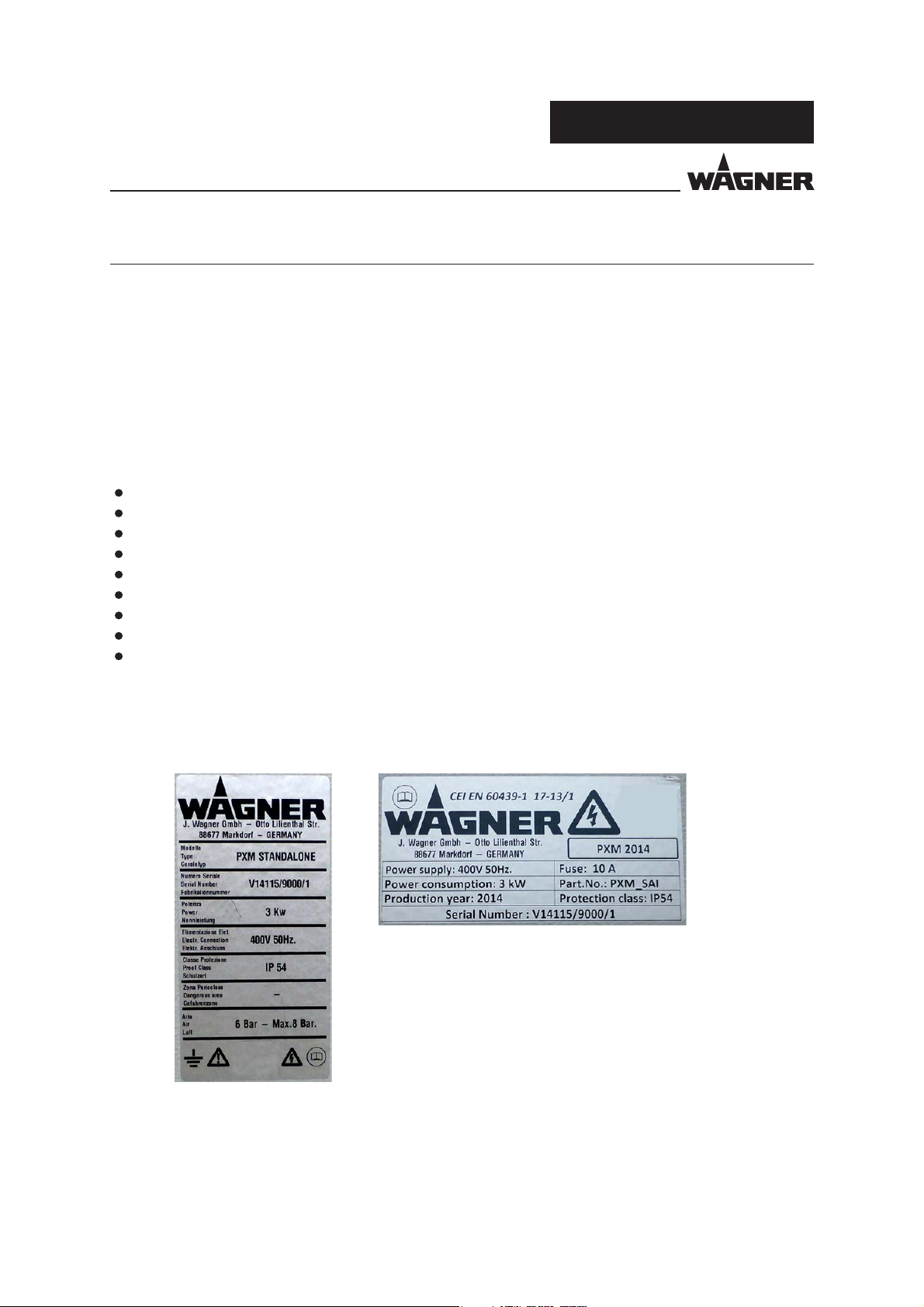
3.3 TYPE PLATE
Powder center Control cabinet
P_02628
P_02627
Note:
The type plate may only be attached with the CE mark if the complete installation
(powder center, controller, add-on parts, etc.) complies with the provisions of the
EC directives.
12
Page 13
VERSION 08/2015 ORDER NUMBER DOC2350372
OPERATING AND ASSEMBLY MANUAL
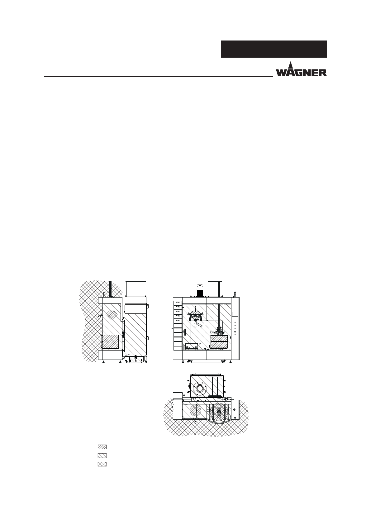
3.4 NOTE ON THE EXZONE CLASSIFICATION BY THE OPERATOR
Decreased intrinsic emission is used by the PXM powder center to create a reduced zone
extension as compared to classi cation and presentation as per EN 12981 (version 2010/06)*
and BGI 764 (version 2009/10, as per 2014/02)*.
The permanent openings are facilitated. It is ensured by design and construction.
Therefore, operation is permitted only upon compliance with all the following requirements:
– The minimum air extraction rate corresponds to the operating manual and is ensured
– The powder center can only be operated when technical ventilation equipment is
active (interlock with exhaust air)
– The open box is not uidized, the uidized box is only operated with "cover for box"
– The uidized tank is closed with "cover for uidized tank"
– The powder hoses and connections are airtight
– Necessary cleaning times are kept short
– The notes in the operating manual on safe operation are being observed.
PXM
Compliance with all the requirements and measures results in no relevant powder
discharge. The zone extension caused by the powder center can be seen in the following
images:
P_02590
Zone 20 in the tank and in the sieve chamber of the ultrasonic sieve
Zone 22 within the powder center
No zone caused by the powder center
* The EU standard and BG information are being revised. The exemptions shall be taken
into account in future versions.
13
Page 14
VERSION 08/2015 ORDER NUMBER DOC2350372
OPERATING AND ASSEMBLY MANUAL
4 GENERAL SAFETY INSTRUCTIONS
4.1 SAFETY INSTRUCTIONS FOR THE OPERATOR
Keep this operating manual on hand near the device at all times.
Always follow local regulations concerning occupational safety and accident prevention.
4.1.1 ELECTRICAL DEVICES AND EQUIPMENT
To be provided in accordance with the local safety requirements with regard to the
operating mode and ambient in uences.
May only be maintained by skilled electricians.
Must be operated in accordance with the safety regulations and electrotechnical
regulations.
Must be repaired immediately in the event of problems.
Must be decommissioned if they pose a hazard.
Must be de-energized before work is commenced on active parts.
Secure the device against being switched back on without authorization. Inform sta
about planned work.
Observe electrical safety regulations.
PXM
4.1.2 PERSONNEL QUALIFICATIONS
Ensure that the device is only operated, maintained and repaired by trained persons.
4.1.3 SAFE WORK ENVIRONMENT
The oor in the working area must be electrostatically conductive (measurements
according to EN 1081).
Make sure that all persons within the working area are wearing electrostatic-conductive
shoes.
Ensure that gloves worn are made of conductive material.
The powder release must be electrically interlocked with the powder spray system's
exhaust air equipment.
Excess coating product (overspray) must be collected up safely.
Ensure that there are no ignition sources such as naked ames, sparks, glowing wires,
or hot surfaces in the vicinity. Do not smoke.
Maintain su cient quantities of suitable re extinguishers and ensure that they are
serviceable.
The operating company must ensure that an average concentration of powder lacquer
in the air does not exceed 50% of the lower explosion limit (LEL = max. permitted
concentration of powder to air). If no reliable LEL value is available, the average
concentration must not exceed 10 g/m³.
14
Page 15
VERSION 08/2015 ORDER NUMBER DOC2350372
OPERATING AND ASSEMBLY MANUAL
4.2 SAFETY INSTRUCTIONS FOR STAFF
Always follow the information in this manual, particularly the general safety instructions
and the warning instructions.
Always follow local regulations concerning occupational safety and accident
prevention.
Under no circumstances may people with pacemakers enter the area where the
high-voltage eld between the spray gun and the work piece to be coated builds up!
4.2.1 SAFE HANDLING OF WAGNER POWDER SPRAY DEVICES
Do not point spray guns at people.
Before all work on the device, in the event of work interruptions and functional faults:
- Switch o the energy/compressed air supply.
- Secure the spray gun against actuation.
- Relieve pressure on spray gun and device.
- In case of functional faults: Identify and correct the problem, proceed as described
in the "Fault Recti cation" chapter.
PXM
4.2.2 GROUNDING THE DEVICE
The electrostatic charge may, in certain cases, give rise to electrostatic charges on the
device. This may result in the formation of sparks or ames when discharging.
Ensure that the device is grounded before each coating process.
Ground the work pieces to be coated.
Make sure that all persons inside the working area are grounded, e.g., that they are
wearing electrostatically conductive shoes.
The functionality of grounding cables must be checked regularly (see EN 60204).
4.2.3 PRODUCT HOSES
Only use an original WAGNER powder hose.
15
Page 16

VERSION 08/2015 ORDER NUMBER DOC2350372
OPERATING AND ASSEMBLY MANUAL
4.2.4 CLEANING
Before starting cleaning or any other manual work, the high-voltage in the spray area
must be shut down and locked to prevent it from being switched back on.
Lock the compressed air supply and decompress the device.
Secure the device against being switched back on without authorization.
Use only electrically conducting and grounded tanks for cleaning uids.
Preference should be given to non- ammable cleaning uids.
Flammable cleaning liquids may only be used if, after switching o the high-voltage,
all high-voltage conducting parts are discharged to a discharge energy of less than
0.24 mJ before they can be accessed.
Most ammable solvents have an ignition energy of around 0.24 mJ or 60 nC.
The cleaning agent's ash point must be at least 15 K above the ambient temperature.
Only mobile industrial vacuum cleaners of design 1 (see EN 60335-2) may be used to
remove dust deposits.
PXM
4.2.5 HANDLING POWDER LACQUERS
When preparing or processing the powder and cleaning the device, take note of the
processing regulations laid down by the manufacturer of the powder lacquers being
used.
Take note of the manufacturer’s instructions and the relevant environmental protection
regulations when disposing of powder lacquers.
Implement the prescribed safety measures, in particular the wearing of safety glasses
and safety clothing as well as the use of protective hand cream.
Use a mask or breathing apparatus if necessary.
To ensure su cient protection of health and the environment, only operate the device
in a powder booth or on a spray wall with activated ventilation (exhaust air).
16
Page 17
VERSION 08/2015 ORDER NUMBER DOC2350372
OPERATING AND ASSEMBLY MANUAL
5 DESCRIPTION
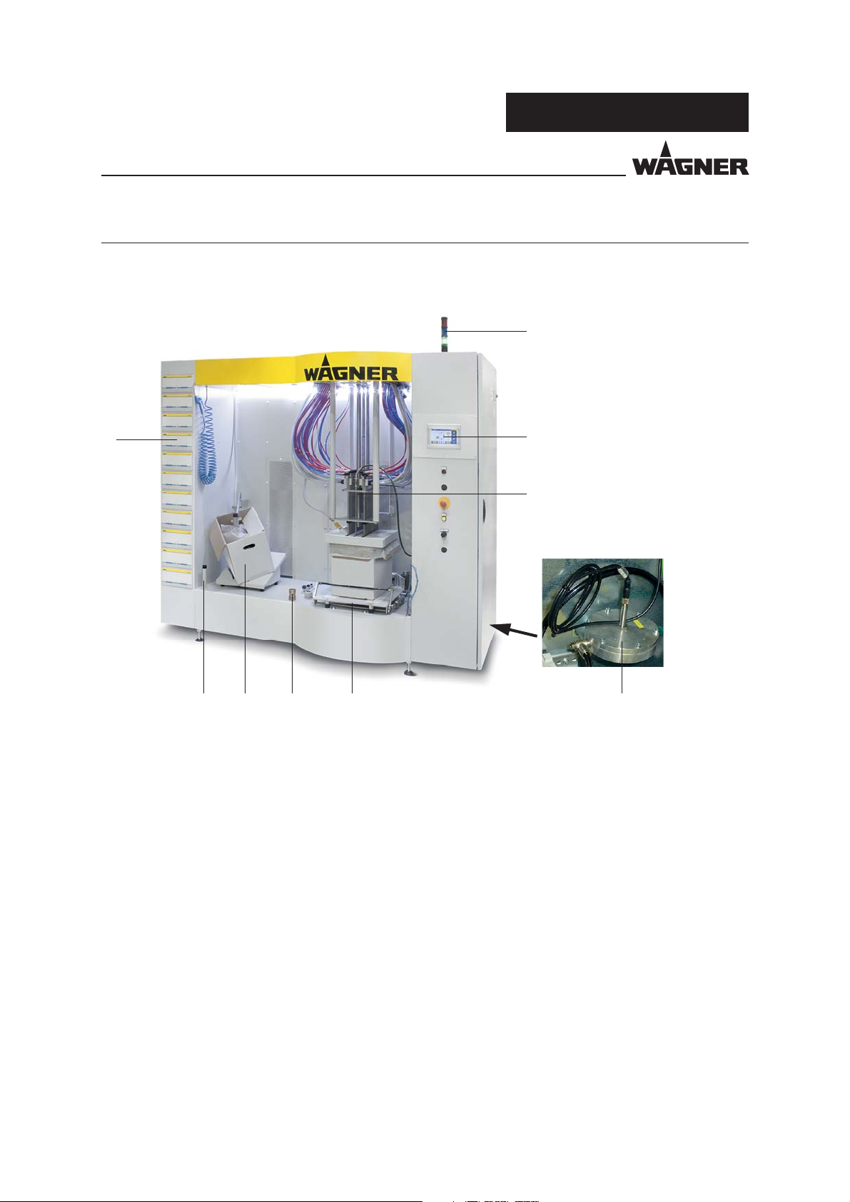
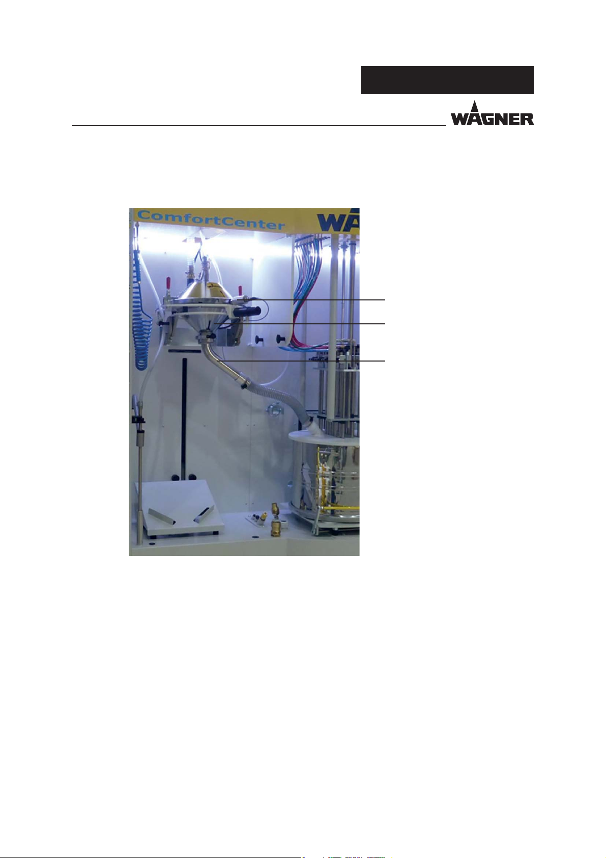
5.1 COMPONENTS
PXM
2
1
P_02520
6789
1 Rack for EPG control units
2 Warning lamp with built-in alarm horn
3 Control cabinet with operating elements
4 Reciprocator with powder injectors and intake systems
5 Level sensor
6 Holder for box or container
7 Cleaning station for reclaimed powder; park station for loss mode of operation
8 Fresh powder supply
9 Cleaning position for fresh powder lance
3
4
5
17
Page 18

VERSION 08/2015 ORDER NUMBER DOC2350372
OPERATING AND ASSEMBLY MANUAL
5.1.1 VERSION WITH INTEGRATED FILTER
10
PXM
11
P_02521
14
10 Filter suction
11 Fresh powder pump
12 Pressure switch for monitoring the mains pressure
13 Adapter for lter suction
Alternatively: Adapter to connect to the nal lter
14 Powder catch basin
13
12
18
Page 19

VERSION 08/2015 ORDER NUMBER DOC2350372
OPERATING AND ASSEMBLY MANUAL
5.1.2 VERSION FOR FINAL FILTER
PXM
P_02674
19
Page 20
VERSION 08/2015 ORDER NUMBER DOC2350372
OPERATING AND ASSEMBLY MANUAL
5.1.2 VERSION WITH ULTRASONIC SIEVE
PXM
1
2
3
P_02675
1 Sieve frame with converter
2 Sieve housing
3 Powder spout
20
Page 21
VERSION 08/2015 ORDER NUMBER DOC2350372
OPERATING AND ASSEMBLY MANUAL
5.2 MODE OF OPERATION
The PXM powder center is a system from which uidized powder is conveyed simultaneously
from a powder tank (option) to several spray guns. Powder consumption is compensated
by the fresh powder feed device (option) in the powder center or by manually re lling.
The linear motion unit suction system is immersed directly into the powder tank.
A homogenous powder/air mixture is created through the uidization and vibration
(option) of the tank. The injectors convey the powdered paint to the guns in the coating
system. A lowered powder level in the tank is detected by the level sensor in conjunction
with sensors on the reciprocator. The level sensor also triggers the lowering of the suction
system and the fresh powder supply (option) when necessary. A warning is triggered
automatically in the event of a powder shortage and the warning lamp lights up yellow.
If the minimum level is not reached after a certain time, the alarm lights up red and the
system registers a malfunction. Powder level monitoring is active only in automatic mode.
PXM
5.3 PROTECTIVE AND MONITORING EQUIPMENT
Protective and monitoring equipment must not be removed, modi ed or rendered
unusable.
Regularly check for perfect functioning.
If defects are detected on protective and monitoring equipment, the system must not
be operated until these defects are remedied.
Safety Device E ect
EMERGENCY STOP button – Powder feed blocked
– Linear motion unit blocked
– Fluidization and vibrator deactivated
21
Page 22
VERSION 08/2015 ORDER NUMBER DOC2350372
OPERATING AND ASSEMBLY MANUAL
5.4 SCOPE OF DELIVERY
Quantity Order No. Designation
1 see Chapter 5.4.1 PXM powder center
The standard equipment includes:
1 Declaration of incorporation
1 2350371 Operating and assembly manual, German
1 see Chapter 1.3 Operating and assembly manual in the local language
5.4.1 DESIGN VARIANTS OF THE PXM POWDER CENTER
Basic Module:
Order No. Designation
2350977 Powder center PXM 20/22 IF standalone, without ultrasonic sieve
2350980 Powder center PXM 20/22 FF standalone, without ultrasonic sieve
2359437 Powder center PXM 34 IF standalone, without ultrasonic sieve
Powder center PXM 34 FF standalone, without ultrasonic sieve
PXM
Expansion Modules*:
Order No. Designation
2350981 Injector set PI-F1
2350982 Injector set HiCoat-ED
2350983 Set EPG S2
2350984 EPG rack 1–11 for PXM 20/22
2359443 EPG rack 1–18 for PXM 34
2350987 Vibration table container/box
2350988 Box uidizing device (only possible for PXM 20/22)
2350990 Box fresh powder addition
2341584 External valve cabinet for single-plug conveyor
2353462 Extension set ultrasonic sieve device 160 μm
2353306 Extension set ultrasonic sieve device 200 μm
2353302 Controller extension bigbag (without bigbag)
2350985 Set connection material for injectors and EPG including installation
* Expansion modules can be used only in conjunction with an order of the basic module.
Product-speci c limitations, e.g., ow rates must be observed and taken into account during the con guration.
22
Page 23
VERSION 08/2015 ORDER NUMBER DOC2350372
OPERATING AND ASSEMBLY MANUAL
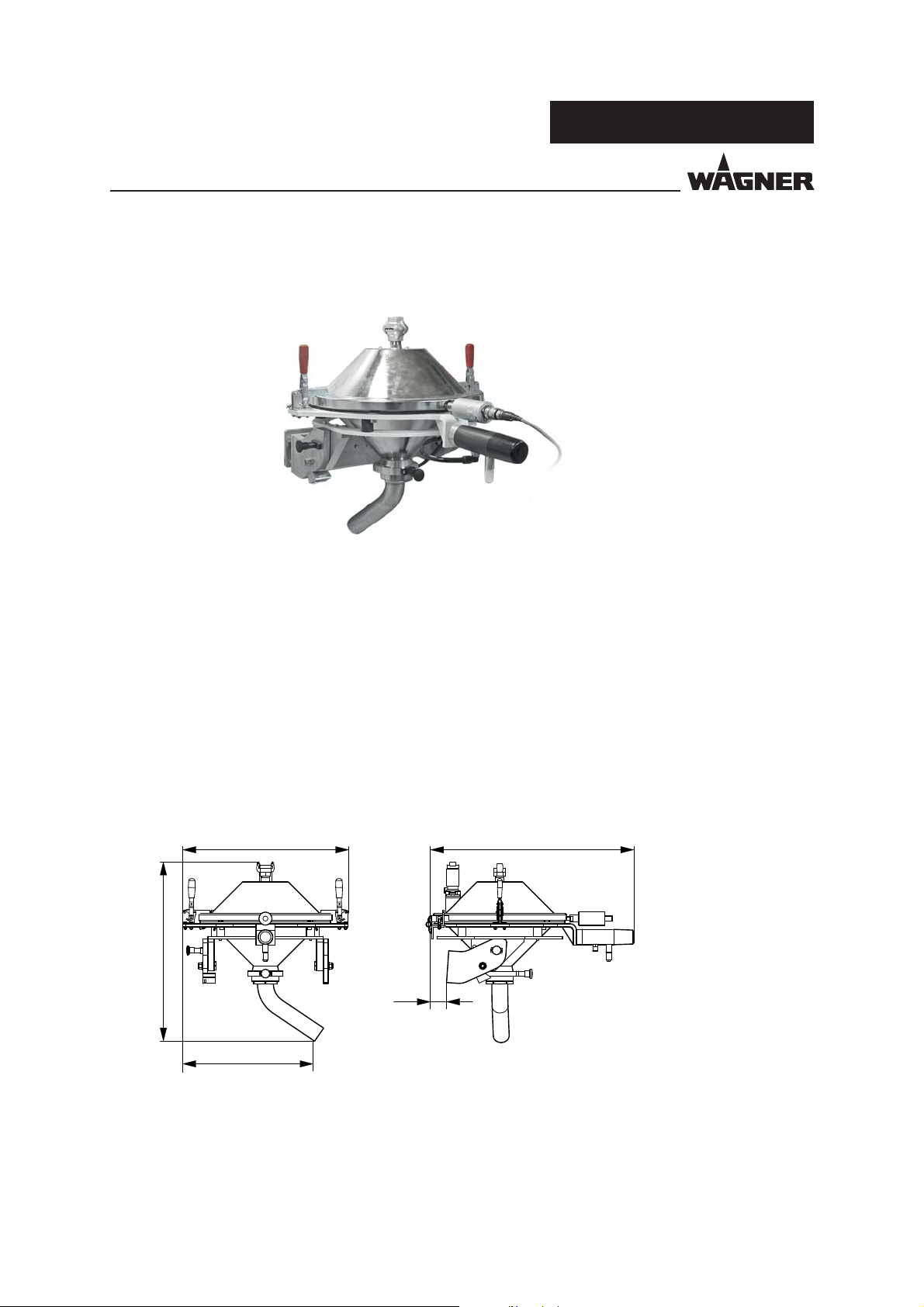
5.4.2 TYPE WITH ULTRASONIC SCREENING UNIT
P_02370
PXM
For more information on the ultrasonic screening unit, see operating manual for ultrasonic
screening unit.
5.4.3 INSTALLATION DIMENSIONS FOR ULTRASONIC SCREENING UNIT
678520
78
P_02561
450
23
Page 24
VERSION 08/2015 ORDER NUMBER DOC2350372
OPERATING AND ASSEMBLY MANUAL
5.5 TECHNICAL DATA
Dimensions:
Maximum height 2,660 mm; 104.72 inches
Maximum width 2,170 mm; 85.43 inches
Maximum depth 1,400 mm; 55.12 inches
Weight Approx. 500 kg + 150 kg lter suction
Electrical:
Three-phase current connection 230/400 V 3P/N/PE 50 Hz
Frequency 50 Hz
Total power consumption 1.5 kW (without lter)/3.7 kW (with lter)
Protection class IP 54
Pneumatic:
Compressed air connection 0.6 – 0.8 MPa; 6 – 8 bar; 87 – 116 psi
Cross-section of compressed air line At least 1.5"
Compressed air quality 6.5.2 according to ISO 8573.1: 2010
Air throughput coating mode 45 Nm³/h; 1,588.88 cf/h
Air throughput cleaning mode 100 – 150 Nm/h in approx. 30 sec.
Suction capacity, exhaust 4,000 m³ at 1,300 Pa; 5,230.86 cubic yards at 0.19psi
Filter surface area (version with lter) 40 m²; 430.55 square foot
Number of lters 2
Filter capacity > 99%
Permanent suction output for version with connection to a nal lter: 1,000 Nm/h; 35,308.34 cf
Equipment:
PXM
WARNING
Exhaust air containing oil!
Risk of poisoning if inhaled.
Provide compressed air free from oil and water
(Quality Standard 7.5.4 as per ISO 8573.1, 2010)
7.5.4 = 5-10mg/m³ / ≤7 °C; 44.6 °F / 5 mg/m³.
Number of injectors PXM 20/22: 20 injectors when feeding from the box
PXM 20/22: 22 injectors when feeding from the uid tank
PXM 34: 34 injectors when feeding from the uid tank
Ambient conditions:
Operating temperature range 5 – 45 °C; 41 – 113 °F
24
Page 25
VERSION 08/2015 ORDER NUMBER DOC2350372
OPERATING AND ASSEMBLY MANUAL
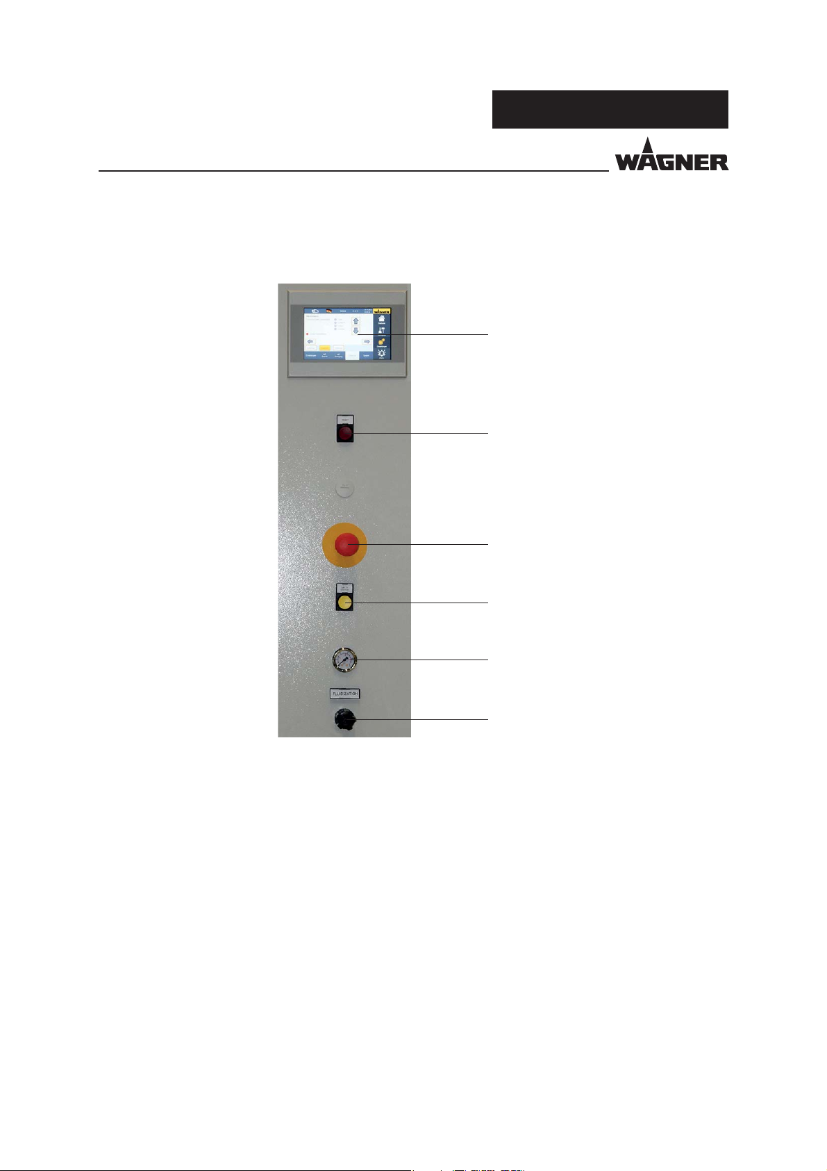
5.6 CONTROLS
PXM
1
2
3
4
5
6
P_02522
1 Touch screen for operating the PXM
2 Fault display: Lights up red when the emergency stop chain is interrupted
Button to reset the EMERGENCY STOP safety relay
3 EMERGENCY STOP switch
4 Safety button for two-hand control function
5 Pressure gauge for uid air
6 Fluid air regulator
25
Page 26
VERSION 08/2015 ORDER NUMBER DOC2350372
OPERATING AND ASSEMBLY MANUAL
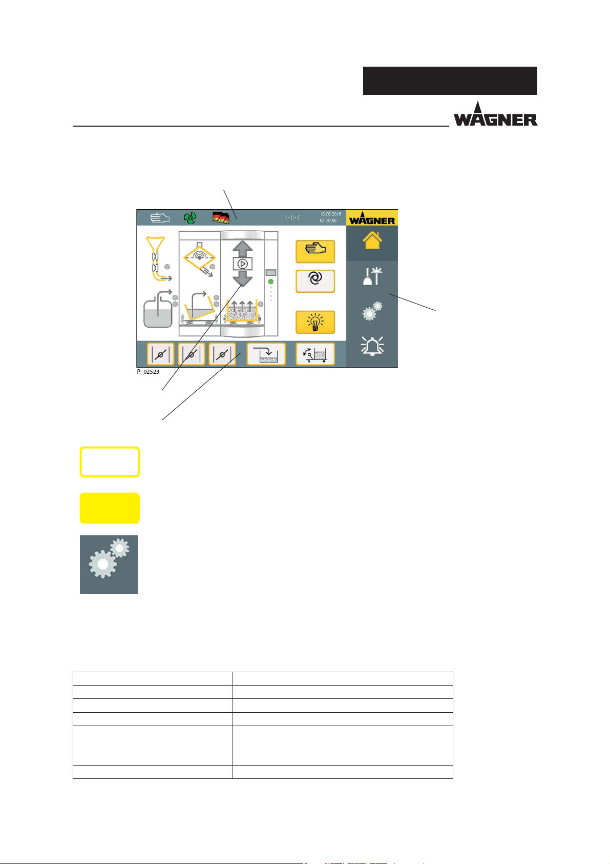
5.7 SCREEN LAYOUT OF THE TOUCH SCREEN
Information bar
Service
PXM
Function graphic
Function bar 1
On
P_02591
On
P_02592
Manual
Auto
Home page
Cleaning
Menu bar
Settings
Alarm
Released functions and components are marked by a yellow frame.
Activated functions and components are depicted by yellow highlighted
icons or buttons.
Non-activatable functions are depicted by a gray font for each function
button and a gray frame.
Settings
P_02593
Tap on the respective component/function on the touch screen to switch things on and o .
The status of the individual components is depicted on the screen by di erent colors of the
points on the respective components:
Status Display Description
Gray Not active
Green Ready
Flashes yellow Warning
Lights up yellow During fresh powder feed in automatic mode:
The fresh powder conveyor is ready to feed powder,
but enough powder is available
Flashes red Malfunction
26
Page 27

VERSION 08/2015 ORDER NUMBER DOC2350372
OPERATING AND ASSEMBLY MANUAL
5.8 EXPLANATION OF THE SCREEN PAGE NUMBERS
The screen pages are numbered from top to bottom (1-4) in the menu bar and from left to
right (1-5) in the function bar.
3 - 2 - 3
Button number in function bar 2
Button number in function bar 1
Button number in the menu bar
PXM
Page number
Service
RP supply
Operating mode
RP feed time [sec]
RP break time [sec]
Message recovery system [sec]
Work station
Settings System
FP
supply
MP
operation
No Yes
Duration Eco
Standard
Standard
RP
supply
MP
cleaning
Exhaust
system
Diagnosis
SAT
Function bar 1
Function bar 2
"Scroll forwards/backwards" buttons
Home page
Cleaning
Settings
Alarm
Menu bar
27
Page 28

VERSION 08/2015 ORDER NUMBER DOC2350372
OPERATING AND ASSEMBLY MANUAL
5.9 INPUTS ON THE TOUCH PANEL
Pulse time [sec]
Exhaust system
PXM
Home page
Filter cleaning
Filter cleaning
Work station
Settings System
MP
operation
MP
cleaning
Diagnosis
Cleaning
Settings
Alarm
To modify number values, touch the value that is to be modi ed and the keypad shown
above appears.
The minimum and maximum setting values are displayed on the right; lower or higher values
are not applied.
Button assignment:
BACK Cancel: the entered value is not applied.
EXIT The input eld is left without applying the set value.
ENTER The entered value is applied.
5.10 DISPLAYS ON THE WARNING LAMP
Illuminated Display Description
Green
Flashes red brie y Warning
Flashes red at regular intervals Malfunction
Blue Cleaning is active
Alarm horn sounds Malfunction
Powder center ok ➔ No malfunction
– Exhaust air OK
– Ventilator is running
28
Page 29
VERSION 08/2015 ORDER NUMBER DOC2350372
PXM
OPERATING AND ASSEMBLY MANUAL
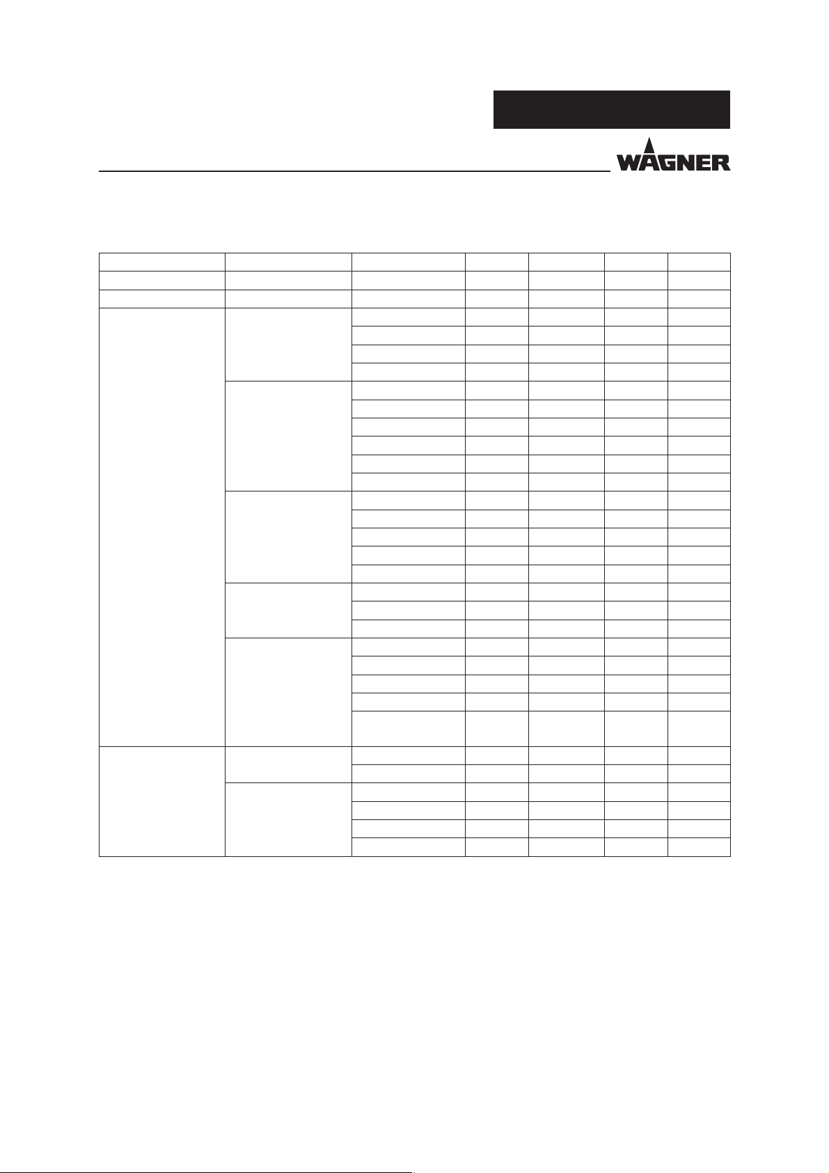
5.11 USER RIGHTS
Main menu Sub-menu Function Worker Supervisor Service Facility
Home page x x x x
Cleaning x x x x
Settings Settings Workstation x x x x
Powder supply x x x x
US Sieve x x x x
Test x
MP operation Workstation x x x
FP supply x x x
RP supply x x x
Exhaust system x x x
US Sieve x x x
Hardware x x x
MP cleaning Interface x x x
Injectors x x x
FP supply x x x
RP supply x x x
US Sieve x x x
Diagnosis LogView x x
Diagnosis x x
Maintenance x x
System Password x x x
Data backup x x x
Backup x x x
IP setting x x
Exit visualization
software
Alarm Current View x x x x
Con rm x x x x
History View x x x x
Save as *.csv x x x
Save as *.xml x x x
Delete x
xx
29
Page 30
VERSION 08/2015 ORDER NUMBER DOC2350372
OPERATING AND ASSEMBLY MANUAL
6 ASSEMBLY AND COMMISSIONING
6.1 TRAINING THE ASSEMBLY STAFF
WARNING
Incorrect installation/operation!
Risk of injury and damage to the device.
The assembly and commissioning sta must have the technical
skills to safely commission the device.
When assembling, commissioning and performing all work,
please read and observe the operating manual and safety
regulations of the additionally required system components.
PXM
A skilled person must check to ensure that the device is in a reliable state after it is installed
and commissioned.
6.2 STORAGE CONDITIONS
Until the point of assembly, the powder center must be stored in a dry location, free from
vibrations and with a minimum of dust. The powder center must be stored in closed rooms.
The air temperature at the storage location must be between +10 °C and +20 °C
(+50 °F and +68 °F).
The relative air humidity at the storage location must be between 20 and 70%
(without condensation).
6.3 INSTALLATION CONDITIONS
The air temperature at the installation site must lie between +10 °C and +30 °C
(+50 °F and +86 °F).
The relative air humidity at the installation site must be between 20 and 70%
(without condensation).
30
Page 31

VERSION 08/2015 ORDER NUMBER DOC2350372
OPERATING AND ASSEMBLY MANUAL
6.4 TRANSPORTATION
WARNING
Parts have high weights and centers of gravity!
Risk of injury and damage to the device.
Only use appropriate lifting tackle (crane, fork lift) for assembly.
Secure the parts against tipping during transport.
Cordon o assembly area to keep out unauthorized persons.
The powder center is delivered completely mounted to the site of installation. This may be
supplied separately for a version with its own lter suction.
Final assembly is performed on-site.
PXM
Transportation and warehouse operations may only be performed by quali ed personnel,
especially in the use of industrial trucks, ladders and cranes.
The selected means of transport must be suitable and permissible for the respective
component weights.
For the insertion of parts at the installation site, an opening width of at least 2,000 mm
(6.56 ft.) must exist, and an opening height of 2,000 mm (6.56 ft.).
The PXM powder center is delivered upright.
P_02571
Support with wooden beams on the truck Loading/unloading with forklift
P_02572
31
Page 32

VERSION 08/2015 ORDER NUMBER DOC2350372
OPERATING AND ASSEMBLY MANUAL
PXM
P_02573
Transport in the factory workshop Support with wooden beams on the
P_02574
lter module
6.5 ASSEMBLY AND INSTALLATION
WARNING
Danger from electric current!
Risk of injury and damage to the device.
Before connecting the device, ensure that the external controller
is switched o and the EMERGENCY STOP button is actuated.
The device may only be put into operation if it complies with the essential requirements of
Directive 2006/42/EC after installation.
The requirements of the relevant paragraphs must be met in particular:
– 1.1.4 Illumination
– 1.2.4.1 Normal shutdown
– 1.2.4.3 Emergency shutdown
– 1.2.4.4 Assemblies of machinery
– 1.2.5 Selecting the control or operating modes
– 1.2.6 Power supply malfunction
– 1.3.7 Risks from moving parts
– 1.3.8 Selection of protective equipment against risks from moving parts
– 1.5.6 Fire
– 1.5.16 Lightning
– 1.7.1.2 Warning devices
32
Page 33

VERSION 08/2015 ORDER NUMBER DOC2350372
OPERATING AND ASSEMBLY MANUAL
P_02575
PXM
1. Fasten lter module (if available) to the powder center housing.
It is fastened with 12 screws from the back; two screws must have contact disks for
proper grounding.
P_02576
2. Connect the compressed air supply to the air connection point (air connection point1";
supply at least 1.5"; pressure regulator setting 6 bar).
3. Introduce the electrical cables from the top or from the back and connect these to
the main terminal.
33
Page 34

VERSION 08/2015 ORDER NUMBER DOC2350372
OPERATING AND ASSEMBLY MANUAL
PXM
P_02577
P_02578
4. Erect the piston cylinder and guide the piston through the roof.
The limit switches must be located on the left side (seen from the front).
5. Use 4 screws to fasten piston cylinder onto the roof.
Workstation
Position switch of linear motion
unit
Powder level sensor
LogView Diagnosis Maintenance
Settings System
MP
operation
at the top
Warning
Minimum
Cleaning
MP
cleaning
Diagnosis
Home page
Cleaning
Settings
Alarm
6. Connect the compressed air and power supply.
7. Move the cylinder downwards via the touch screen (diagnostic page) and screw into place.
34
Page 35

VERSION 08/2015 ORDER NUMBER DOC2350372
OPERATING AND ASSEMBLY MANUAL
P_02581
8. Align the ange by hand and use 3 screws to fasten onto the injector retaining plate.
PXM
Workstation
Position switch of linear motion
unit
Powder level sensor
LogView Diagnosis Maintenance
Settings System
MP
operation
at the top
Warning
Minimum
Cleaning
MP
cleaning
Diagnosis
Home page
Cleaning
Settings
Alarm
9. Move the piston cylinder via the diagnostic side to adjust the limit switches.
35
Page 36

VERSION 08/2015 ORDER NUMBER DOC2350372
OPERATING AND ASSEMBLY MANUAL
2
3
1
4
P_02622
PXM
Limit switch 1: Top = Cylinder moved all the way up.
Setting: Uppermost cylinder position
Limit switch 2: Warning = Advance warning that the powder level will be reached soon.
Setting: 2 cm above limit switch 3
Limit switch 3: Minimum = Powder level minimum; cylinder does not move further
downwards.
Setting: Fluid tubes 1 cm from the uid oor of the tank; use tank
Order No. 3304505.
Limit switch 4: Cleaning = Intake tubes dip into blowout nozzles.
Setting: Intake tube 1 cm in blowout nozzle
P_02583
10. Horizontally align the PXM using the leveling feet on the frame.
11. Align the intake tubes so that they meet centrally in the blowout nozzles.
To do this, rst align the PXM with the leveling feet.
If necessary, loosen the four screws from the mounting plate of the blowout nozzles
and bring the nozzles into position.
36
Page 37

VERSION 08/2015 ORDER NUMBER DOC2350372
OPERATING AND ASSEMBLY MANUAL
6.6 GROUNDING
For safety reasons the system must be properly grounded. WAGNER recommends the use
of a copper cable of at least 16 mm² with su cient mechanical resistance for connection
to the signal ground.
Good grounding of the work piece is also necessary for optimum powder coating.
A poorly grounded work piece causes:
dangerous electric charging of the work piece,
very poor wrap-around,
uneven coating,
back spraying to the gun, i.e., contamination
Prerequisites for perfect grounding and coating are:
Conducting suspension for the work piece that is to be coated.
Grounding of the powder coating booth, transport and suspension equipment to
be provided on site in accordance with the corresponding operating manuals or the
de nitions laid down by the manufacturer.
Regular cleaning of hangers from powder residues.
Grounding resistance for the work piece of a maximum of 1 MΩ (megaohm).
Grounding cable connected to the controller module or control cabinet.
PXM
Sparks between work piece and conveyor hooks (hangers) can occur if hooks or
other hanger parts are not completely cleaned! These sparks can cause heavy radio
frequency interference.
6.7 SAFETY CHECKS
Perform safety checks in accordance with Chapter 8.2.3.
37
Page 38

VERSION 08/2015 ORDER NUMBER DOC2350372
OPERATING AND ASSEMBLY MANUAL
6.8 COMMISSIONING
The tank mounting and injector mounting plate must be horizontally aligned in all
directions.
The hose for the uid air must either be connected to the terminal for the box- uidizing
device ( oor) or on the powder tank.
PXM
P_02589
NOTICE
Positioning of powder tank and tank cover!
Danger of damage to the device.
Align the powder tank or powder box on the vibrator table so that the suction system
can move in and out unimpeded.
Only insert the cover into the guides and push it back to the limit stop after lowering
the suction tubes.
Remove cover before powering up the intake tubes.
38
Page 39

VERSION 08/2015 ORDER NUMBER DOC2350372
OPERATING AND ASSEMBLY MANUAL
6.9 STANDARD SETTINGS
The most important settings for speedy commissioning of the powder center have already
been carried out by the manufacturer.
You can, however, change standard settings to suit your needs. The changes remain saved
even if the powder center is switched o with the main switch.
The following standard settings are made in the factory.
6.9.1 MACHINE PARAMETERS OPERATION
Workstation
Alarm delay powder shortage: 30 sec.
FP supply
FP station: 1
FP bigbag: 1
Bigbag type: IP 5000
FP redosing time manual: 30 sec.
FP redosing time automatic: 30 sec.
RP supply
RP supply: Yes
Operating mode: Eco
RP feed time: 50 sec.
RP break time: 10 sec.
Message recovery system: 60 sec.
RP supply: Cycle 1: 2.5 sec.
Cycle 2: 0.3 sec.
Cycle 3: 2.5 sec.
Cycle 4: 0.3 sec.
US sieve
US sieve: No
After-run time if US sieve available: 30 sec.
Dirt discharge: 3 pulses
After-run time before: 12 sec.
Wait time: 10 min.
Pulse time: 1.0 sec.
Break time: 5.0 sec.
Exhaust system
Exhaust system: Integrated
Filter cleaning pulse time: 0.2 sec.
Filter cleaning break time: 60 sec.
Final lter, automatic closing: 10 sec.
PXM
39
Page 40

VERSION 08/2015 ORDER NUMBER DOC2350372
OPERATING AND ASSEMBLY MANUAL
6.9.2 MACHINE PARAMETER CLEANING
Interface
Communication with the application controller: No
Injectors
Preliminary cleaning Block 1
Number of pulses: 2
Pulse time: 0.2 secs
Break time: 1 secs
Preliminary cleaning Block 2
Number of pulses: 2
Pulse time: 0.2 secs
Break time: 1 secs
Cleaning Block 1
Number of pulses: 8
Pulse time: 0.5 secs
Break time: 2 secs
Cleaning Block 2
Number of pulses: 8
Pulse time: 0.5 secs
Break time: 2 secs
Dynamics: O
FP supply
Pre-cleaning
Number of pulses: 2
Pulse time: 0.5 secs
Break time: 2.0 secs
Cleaning
Pulse time: 1.0 secs
Break time: 2.0 secs
RP supply
Cleaning
Number of pulses: 10
Pulse time: 1.0 secs
Break time: 2.0 secs
US sieve
Pre-cleaning
Number of pulses: 5
Pulse time: 0.2 secs
Break time: 2.0 secs
Cleaning
Number of pulses: 5
Pulse time: 0.5 secs
Break time: 2.0 secs
PXM
40
Page 41

VERSION 08/2015 ORDER NUMBER DOC2350372
OPERATING AND ASSEMBLY MANUAL
6.9.3 CAN ADDRESSES FOR MCM SYSTEM
CAN Node Module Type Application
0 CAN Diagnosis Do not use
1 CAN Open Master 1 MCM CAN 1
2 CAN Open Master 2 MCM CAN 2
3 I/O Module MCM CPS
11 HU1 No. 1 Sliding table 1
12 HU1 No. 2 Sliding table 2
13 HU1 No. 3 Sliding table 3
14 HU1 No. 4 Sliding table 4
21 VU1 No. 1 Reciprocator 1
22 VU1 No. 2 Reciprocator 2
23 VU1 No. 3 Reciprocator 3
24 VU1 No. 4 Reciprocator 4
PXM
31 EPG S2 No. 1 Guns 1 and 2
32 EPG S2 No. 2 Guns 3 and 4
33 EPG S2 No. 3 Guns 5 and 6
34 EPG S2 No. 4 Guns 7 and 8
35 EPG S2 No. 5 Guns 9 and 10
36 EPG S2 No. 6 Guns 11 and 12
37 EPG S2 No. 7 Guns 13 and 14
38 EPG S2 No. 8 Guns 15 and 16
39 EPG S2 No. 9 Guns 17 and 18
40 EPG S2 No. 10 Guns 19 and 20
41 EPG S2 No. 11 Guns 21 and 22
42 EPG S2 No. 12 Guns 23 and 24
43 EPG S2 No. 13 Guns 25 and 26
44 EPG S2 No. 14 Guns 27 and 28
45 EPG S2 No. 15 Guns 29 and 30
46 EPG S2 No. 16 Guns 31 and 32
61 Light curtain portal Kontur 2, with Quattro CAN Open
62 CML 720 light curtain CML 720i height light curtain
63 CML 720 light curtain CML 720i depth light curtain, right
64 CML 720 light curtain CML 720i depth light curtain, left
65 CML 720 light curtain CML 720i code catching
81 Extension module for recipe selection (11 bit)
82 … 127 not de ned free application
41
Page 42

VERSION 08/2015 ORDER NUMBER DOC2350372
OPERATING AND ASSEMBLY MANUAL
6.9.4 EPG S2 SETTINGS
Normally, these settings have been made prior to shipment. The description is for reference
purposes only and when an error message is displayed.
PXM
Mains power IN / OUT
Netz EIn / Ausgang
P_02714
Prim. Fuse
Sicherung
1.0 AT
(slow blow)
Feeding air
Förderluft
Air input
Lufteingang
Dosage air
Dosierluft
Made in Switzerland
J. Wagner AG
CH 9450 Altstätten
0102
Type / Typ:
EPG S2 FM
Voltage:
90-250 VAC 47-63 Hz
Spannung:
Line Power:
Eingangsleistung:
FM approved for CL II, Div 2 Grps E, F, & G
Ambient temp range 5C to 45C T5
Use in accordance with
control document:
Serial No.:
Serie Nr.:
max. 65 W
2309729
Do NOT connect or disconnect
when ENERGIZED !
Controller is suitable for Class II,
Division 2, Hazardous (Classified)
locations.
For operation all ports must be fitted
with a plug or the protection cap.
Overvoltage Category II
and pollution Degree 2
IN CAN Bus OUT
Data and Interlock
Daten und Verriegelung
B
Spraygun
Sprühpistole
A
Output to gun
Ausgang zur Pistole
U max. 22 Vpp
I max. 0,9 A
AABB
Atomizing air
Zerstäuberluft
Feeding air
Förderluft
Dosage air
Dosierluft
Atomizing air
Zerstäuberluft
CAN bus node ID setting
CAN bus baud rate setting/emergency operation mode
42
Page 43

VERSION 08/2015 ORDER NUMBER DOC2350372
OPERATING AND ASSEMBLY MANUAL
Switch CAN baud rate Maximum
1234
0 0 0 X 1,000 kBit/s 25 m
10
1 2 3 4
Baud rate
P_01509
Shown example: Factory setting 250 kBit/s
Setting address of each EPG S2, starting from 31 for the rst EPG S2 (from top to bottom)
0 0 1 X 800 kBit/s 50 m
ON
0 1 0 X 500 kBit/s 100 m
0 1 1 X 250 kBit/s 250 m
1 0 0 X 125 kBit/s 500 m
1 0 1 X 100 kBit/s 1,000 m
1 1 0 X 50 kBit/s 1,000 m
1 1 1 X 20 kBit/s 1,000 m
cable length
PXM
CAN Node Module Type Application
31 EPG S2 No. 1 Guns 1 and 2
32 EPG S2 No. 2 Guns 3 and 4
33 EPG S2 No. 3 Guns 5 and 6
34 EPG S2 No. 4 Guns 7 and 8
35 EPG S2 No. 5 Guns 9 and 10
36 EPG S2 No. 6 Guns 11 and 12
37 EPG S2 No. 7 Guns 13 and 14
38 EPG S2 No. 8 Guns 15 and 16
39 EPG S2 No. 9 Guns 17 and 18
40 EPG S2 No. 10 Guns 19 and 20
41 EPG S2 No. 11 Guns 21 and 22
42 EPG S2 No. 12 Guns 23 and 24
43 EPG S2 No. 13 Guns 25 and 26
44 EPG S2 No. 14 Guns 27 and 28
45 EPG S2 No. 15 Guns 29 and 30
46 EPG S2 No. 16 Guns 31 and 32
3
4
2
5
1
6
0
7
9
8
3
4
2
5
1
6
0
7
9
8
Node ID 01 (0/1)
1
0
P_02715
3
4
2
5
6
7
9
8
3
4
2
5
1
6
0
7
9
8
Node ID 23 (2/3)
43
Page 44

VERSION 08/2015 ORDER NUMBER DOC2350372
OPERATING AND ASSEMBLY MANUAL
6.10 FUNCTION TEST
The function test is performed after the system has been con gured.
Test all the functions on the touch screen in manual mode
Test the cleaning process
Test uidization
Test fresh powder pump
Test automatic operation
PXM
44
Page 45

VERSION 08/2015 ORDER NUMBER DOC2350372
OPERATING AND ASSEMBLY MANUAL
PXM
45
Page 46

VERSION 08/2015 ORDER NUMBER DOC2350372
OPERATING AND ASSEMBLY MANUAL
7 OPERATION
7.1 TRAINING THE OPERATING STAFF
WARNING
Incorrect operation!
Risk of injury and damage to the device.
The operating sta must be quali ed to operate the entire system.
The operating sta must be familiar with the potential risks
associated with improper behavior as well as the necessary
protective devices and measures.
Before work commences, the operating sta must receive
appropriate system training.
PXM
7.2 SAFETY INSTRUCTIONS
Observe safety instructions in Chapter 4.
WARNING
Incorrect operation!
Risk of injury and damage to the device.
Take appropriate precautionary measures, e.g. wear protective
clothing, if contact with powder products or cleaning agents
causes skin irritation.
The footwear worn by operating sta must comply with
EN ISO 20344. The measured insulation resistance must not
exceed 100 megohms.
The protective clothing, including gloves, must comply with
EN ISO 1149-5. The measured insulation resistance must not
exceed 100 megohms.
46
Page 47

VERSION 08/2015 ORDER NUMBER DOC2350372
OPERATING AND ASSEMBLY MANUAL
7.3 TOUCH SCREEN OPERATION STANDARD EQUIPMENT
7.3.1 EQUIPMENT WITH FINAL FILTER
PXM
1 4 5 6
13 10
3
2
Manual
Auto
891112
Home page
Cleaning
Settings
Alarm
P_02524
7
1 Peristaltic pump On/O
2 Exhaust system status
3 Ultrasonic sieve device On/O
4 Language selection
5 Reciprocator Up/Down
6 Manual/automatic mode
7 Illumination On/O
8 Button for clamping the tank (box, powder container)*
9 Replenishing fresh powder (manual, time-controlled) On/O
10 Workstation/vibrator uidization On/O
11 Automatic fresh powder supply On/O (only in automatic mode)
12 Throttle valve Open/Closed
13 BigBag fresh powder On/O , as an alternative to the fresh powder supply from the box
* Additional actuation of the safety switch for two-handed operation below the touch
screen required
47
Page 48

VERSION 08/2015 ORDER NUMBER DOC2350372
OPERATING AND ASSEMBLY MANUAL
7.3.2 EQUIPMENT WITH INTEGRATED EXHAUST SYSTEM
PXM
1 4 5 6
1 Peristaltic pump On/O
2 Exhaust system status
3 Ultrasonic sieve device On/O
4 Language selection
5 Reciprocator Up/Down
6 Manual/automatic mode
7 Illumination On/O
8 Button for clamping the tank (box, powder container)*
9 Replenishing fresh powder (manual, time-controlled) On/O
10 Workstation/vibrator uidization On/O
11 Automatic lter cleaning On/O
12 Automatic fresh powder supply On/O (only in automatic mode)
13 Exhaust system On/O // Switchover frequency
Press the button brie y: Switch on suction
Press the button brie y when suction is switched on: Switchover frequency ventilator
Press and hold the button: Switch o suction
14 Bigbag fresh powder On/O , as an alternative to the fresh powder supply from the
box
3
2
P_02529
8912
1114 13
10
7
* Additional actuation of the safety switch for two-handed operation below the touch
screen required
48
Page 49

VERSION 08/2015 ORDER NUMBER DOC2350372
OPERATING AND ASSEMBLY MANUAL
7.4 SET LANGUAGE
Language
PXM
1. Tap "Flag" button in the information bar.
The depicted screen appears.
2. Select the desired language by tapping on the corresponding ag button.
The screen is now displayed in the selected language.
49
Page 50

VERSION 08/2015 ORDER NUMBER DOC2350372
OPERATING AND ASSEMBLY MANUAL
7.5 LOGGING A USER ON/OFF
The currently logged in user is displayed in the information bar, in the example "Factory".
Press the button to change the user; the following display appears.
Factory
Set authorization
Log on user Log o user
PXM
Press the "Log in user" button; the following display appears.
Factory
Password
Enter the password for the desired user level and press the "Enter" button.
It is switched to the desired user level.
Press the "Log off user" button to go back to the lowest level (operator level).
50
Page 51

VERSION 08/2015 ORDER NUMBER DOC2350372
OPERATING AND ASSEMBLY MANUAL
7.6 STARTING/STOPPING COATING
1. Switch the system on.
2. Move the reciprocator all the way to the top (reference).
3. Set the powder tank. For boxes, loosen powder beforehand.
4. When feeding from the powder box: Pull the foil over the box rim until it lies at on
the box walls.
5. Insert uidization and check pressure (start with 0.5 bar setting).
6. Plug the peristaltic pump tube and fresh powder hose onto the loss position.
7. Select the "Automatic" button; the retractor then moves downwards and determines
the powder level.
When using boxes, ensure that the uid device moves past the foil and does not
press it down.
If necessary, retighten the foil.
8. Check uidization and set if necessary.
When using a uid tank, the powder should ow like water without generating
larger bubbles.
When using powder boxes, the powder should be owable in the uid rod area
without generating larger bubbles or dust.
Note: An excessive uid air setting leads to a greater loss of powder.
9. Insert tank cover.
10. Plug the fresh powder hose*
11. Start coating.
12. First switch o the peristaltic pump on the touch screen according to an arbitrary
time, plug the hose *
13. For longer breaks and at the end of production, switch to manual mode and move
the suction system from the tank to the top in reverse order.
Attention: Remove the cover rst.
14. At the end of production, WAGNER recommends you rough clean the system and
ush the injectors, powder hoses and guns (via application controller) and perform
a normal cleaning for the IP 5000 fresh powder pump.
Move the suction device completely up before turning o the system.
Remove tank or box or close with a dummy cover so that no debris can fall into it.
Note: If the PXM is connected to the nal lter, the throttle valves can only be opened
if no coating is applied.
, **
, **
onto the tank cover.
on the tank cover and switch the peristaltic pump on again.
PXM
* When an automatic fresh powder supply is available
** When using an ultrasonic sieve, plug the fresh powder hose directly onto the
connection on the sieve and the peristaltic pump tube on the feedthrough socket
on the base plate of the powder center
51
Page 52

VERSION 08/2015 ORDER NUMBER DOC2350372
OPERATING AND ASSEMBLY MANUAL
7.6.1 PAINT CHANGE COMPONENTS
PXM
P_02676
12345
1 Blowout nozzles for intake tubes
2 Blowout nozzle for the fresh powder hose and peristaltic pump tube
3 Parking station peristaltic pump tube during loss operation
4 Parking station, fresh powder hose
5 Cleaning position, fresh powder lance
52
Page 53

VERSION 08/2015 ORDER NUMBER DOC2350372
OPERATING AND ASSEMBLY MANUAL
7.6.2 CLEANING POSITIONS POWDER HOSES
P_02679
P_02677
Cleaning fresh powder, standard
Loss position, reclaimed powder
PXM
P_02678
Cleaning fresh powder, intensive
P_02680
Cleaning, reclaimed powder
53
Page 54

VERSION 08/2015 ORDER NUMBER DOC2350372
OPERATING AND ASSEMBLY MANUAL
7.7 CONFIGURING THE POWDER CENTER
The con guration of the powder center must be adjusted when rst commissioning or in
special cases.
Con guration is performed in the "Settings" menu item.
Different configuration settings are displayed depending on the user level selected.
Icon explanation:
Button for scrolling to the next screen page
Button for scrolling back to the previous screen page
PXM
P_02621
Number of pulses
Pulse time (duration)
Break time (duration)
54
Page 55

VERSION 08/2015 ORDER NUMBER DOC2350372
OPERATING AND ASSEMBLY MANUAL
7.7.1 SETTINGS
The settings can be temporarily changed and adapted to the speci c work situation.
The maximum con guration is displayed below, i.e. the switches become visible depending
on the con guration.
Meaning of a deselection:
- Icon is nevertheless displayed on the home page (gray)
- Fresh powder feed cannot be switched on (manual mode)
- Deselected components do not work in automatic mode
Workstation
Home page
PXM
Vibrator
Work-
station
Settings
Powder
supply
MP
operation
Yes No
US sieve
MP
cleaning
Diagnosis
System
Cleaning
Settings
Alarm
Parameter: Explanation:
Vibrator Yes: Vibrator available at the workstation
No: No vibrator available at the workstation
Fresh powder supply
Home page
Internal
FP 1
Bigbag 1External Bigbag 2
Cleaning
Work-
station
Settings
Powder
supply
MP
operation
US sieve
MP
cleaning
Diagnosis
System
Settings
Alarm
Parameter: Explanation:
FP 1 Fresh powder pump 1 is active (selected)
55
Page 56

VERSION 08/2015 ORDER NUMBER DOC2350372
OPERATING AND ASSEMBLY MANUAL
7.7.2 MACHINE PARAMETERS OPERATION
The settings in the "Operation" machine parameters are normally not changed since they
are defined by the installed hardware.
PXM
Fault trigger delay powder
shortage
WS cylinder lowering
Feeding rate [sec]
WS cylinder lowering
Break time [sec]
Time setting for level
controller [sec]
Work-
station
Settings System
FP
supply
MP
operation
RP
supply
MP
cleaning
Parameter: Explanation:
Fault trigger delay powder
shortage
WS cylinder lowering
Feeding rate [sec]
WS cylinder lowering
Break time [sec]
Time setting for level
controller [sec]
Delay time after which an error message is triggered in
the case of powder shortage
Period of time in which the workstation cylinder is
supplied with compressed air during raising and lowering
Period of time in which the workstation cylinder is not
supplied with compressed air during raising and lowering
Delay time after which the linear motion unit lowered
during a powder shortage and the fresh powder pump
is switched on
Exhaust
system
Diagnosis
Standard
Home page
Cleaning
Settings
Alarm
56
Page 57

VERSION 08/2015 ORDER NUMBER DOC2350372
OPERATING AND ASSEMBLY MANUAL
PXM
FP station
FP bigbag
Bigbag type
FP redosing time man. [sec]
FP redosing time auto [sec]
Work-
station
Settings System
FP
supply
MP
operation
No
No
RP
supply
MP
cleaning
Standard
Exhaust
system
Diagnosis
Home page
Cleaning
Settings
Alarm
Parameter: Explanation:
FP station No: No fresh powder pump available
1: A fresh powder pump is available (installed)
2: Two fresh powder pumps are available (installed)
FP Bigbag No: No fresh powder pump available on the bigbag
1: An external fresh powder pump is available (installed)
2: Two external fresh powder pumps are available (installed)
Bigbag type
FP redosing time man. [sec] Redosing time of the fresh powder pump in manual mode
FP redosing time auto [sec] Redosing time of the fresh powder pump in automatic mode
If the "FP bigbag" parameter is set to 1 or 2, then the "Bigbag type" parameter is displayed.
57
Page 58

VERSION 08/2015 ORDER NUMBER DOC2350372
OPERATING AND ASSEMBLY MANUAL
PXM
RP supply
Operating mode
Message recovery system [sec]
Work-
station
Settings System
FP
supply
MP
operation
Yes
Duration
RP
supply
MP
cleaning
No
Eco
Standard
Exhaust
system
Diagnosis
Home page
Cleaning
Settings
Alarm
Parameter: Explanation:
RP supply Yes: Reclaimed powder pump available
No: No reclaimed powder pump available
SAT: Speci c con guration for the SAT system
Operating mode Duration: Peristaltic pump operates continuously
Eco: Peristaltic pump works per cycle, that is, it
works during the "Feed time" adjustable time and
subsequently switches off for the "Break time"
adjustable time (power saving mode)
Message recovery system [sec] A timer runs at the speci ed time after the initial
feed after cleaning. After this time expires, a note is
displayed on the screen to plug the recovery hose
from the loss position to the recovery position.
58
Page 59

VERSION 08/2015 ORDER NUMBER DOC2350372
OPERATING AND ASSEMBLY MANUAL
PXM
RP supply
Operating mode
RP feed time [sec]
RP break time [sec]
Message recovery system [sec]
Work-
station
FP
supply
MP
operation
Yes
Duration Eco
RP
supply
MP
cleaning
No
Standard
Standard
Exhaust
system
DiagnosisSettings System
Home page
Cleaning
Settings
Alarm
Parameter: Explanation:
RP supply Yes: Reclaimed powder pump available
No: No reclaimed powder pump available
SAT: Speci c con guration for the SAT system
Operating mode Duration: Peristaltic pump operates continuously
Eco: Peristaltic pump works per cycle, that is, it works
during the "Feed time" adjustable time and subsequently
switches off for the "Break time" adjustable time (power
saving mode)
RP feed time [sec] Period in which the reclaimed powder pump is running
RP break time [sec] Time in which the reclaimed powder pump is at a standstill
Message recovery system [sec] A timer runs at the speci ed time after the initial feed
after cleaning. After this time expires, a note is displayed
on the screen to plug the recovery hose from the loss
position to the recovery position.
Cycle 3
Exhaust
system
DiagnosisSettings System
Standard
Work-
station
Cycle 1 Cycle 4Cycle 2
FP
supply
MP
operation
cleaning
RP
supply
MP
Parameter: Explanation:
Cycle 1 – 4 Duration of the cycle 1 - 4
Home page
Cleaning
Settings
Alarm
59
Page 60

VERSION 08/2015 ORDER NUMBER DOC2350372
OPERATING AND ASSEMBLY MANUAL
PXM
Integrated
Standard
Exhaust
system
DiagnosisSettings System
Home page
Cleaning
Settings
Alarm
Automatic closing [sec]
Fault trigger delay
ECO input [sec]
Work-
station
operation
FP
supply
MP
Final lterExhaust system
RP
supply
MP
cleaning
Parameter: Explanation:
Exhaust system Final lter: Final lter available
Integrated: Filter module available
Automatic closing [sec] Time in which the throttle valves are automatically closed
after the time expires
Fault trigger delay
ECO input [sec]
Integrated
Standard
Exhaust
system
DiagnosisSettings System
Home page
Cleaning
Settings
Alarm
Filter cleaning pulse time [sec]
Filter cleaning break time [sec]
Fault trigger delay
ECO input [sec]
Work-
station
FP
supply
MP
operation
Final lterExhaust system
RP
supply
MP
cleaning
Parameter: Explanation:
Exhaust system Final lter: Final lter available
Integrated: Filter module available
Filter cleaning pulse time [sec] Duration of the cleaning pulses
Filter cleaning break time [sec] Time in which no lter cleaning takes place
Fault trigger delay
ECO input [sec]
60
Page 61

VERSION 08/2015 ORDER NUMBER DOC2350372
OPERATING AND ASSEMBLY MANUAL
No StandardYesUS Sieve
PXM
After-run time [sec]
Dirt discharge:
After-run time before [sec]
Wait time [min]
US sieve Hardware
MP
operation
MP
cleaning
DiagnosisSettings System
Home page
Cleaning
Settings
Alarm
Parameter: Explanation:
US Sieve Yes: Ultrasonic screening device available
No: No ultrasonic screening device available
After-run time [sec] Sieve continues to run during each switch-o power
signal so that no residual powder remains on the fabric
(damage while blowing out!)
Dirt discharge Number of suction cycles with pulse and break time
After-run time before [sec] Before activating the dirt discharge, the screen
continues running in order to sieve remnants of
powder on the fabric (reduction of powder loss)
Wait time [sec] Interval for debris discharge cycle
Home page
WAGO I/O assignment
Cleaning
US sieve Hardware
MP
operation
MP
cleaning
DiagnosisSettings System
Settings
Alarm
Parameter: Explanation:
WAGO I/O assignment This parameter is used to parameterize the various
con gurations of the powder center.
Each con guration has a di erent CAN node ID.
1: PXM without bigbag/node ID = 5
2: PXM with bigbag/node ID = 6
3: PXM with 34 injectors/node ID = 7
P_02716
61
Page 62

VERSION 08/2015 ORDER NUMBER DOC2350372
OPERATING AND ASSEMBLY MANUAL
7.7.3 MACHINE PARAMETER CLEANING
The settings in the "Cleaning" machine parameters can be optimized for customer-specific
requirements.
Communication with the application controller
Home page
Yes
No
Cleaning
PXM
InjectorsInterface
Settings System
MP
operation
FP
supply
MP
cleaning
Parameter: Explanation:
Communication with the
application controller
Yes: The powder center controller communicates with the
application controller
In doing so, the following information is exchanged in
conjunction with MCC, Pro Tech M or S Pro Tech:
- Move the guns to the cleaning position for internal cleaning
- Switch on the gun air during internal cleaning
- Switch o the gun air after internal cleaning nishes
No: The powder center controller does not communicate
with the application controller
CleaningPre-cleaning Dynamics
Block 2Block 1
Block 1
RP
supply
Diagnosis
Block 2
US sieve
O
Settings
Alarm
Home page
Standard
Interface Injectors
MP
operation
FP
supply
MP
cleaning
Standard
RP
supply
DiagnosisSettings System
On
US sieve
Cleaning
Settings
Alarm
62
Page 63

VERSION 08/2015 ORDER NUMBER DOC2350372
OPERATING AND ASSEMBLY MANUAL
CleaningPre-cleaning
PXM
Home page
Cleaning
Standard
Interface Injectors
MP
operation
InjectorsInterface
MP
operation
Cleaning
supply
cleaning
Standard
supply
cleaning
FP
MP
FP
MP
Standard
RP
supply
DiagnosisSettings System
RP
supply
DiagnosisSettings System
US sieve
US sieve
Settings
Alarm
Home page
Cleaning
Settings
Alarm
Standard
Interface Injectors
MP
operation
FP
supply
MP
cleaning
CleaningPre-cleaning
Standard
RP
supply
DiagnosisSettings System
US sieve
Home page
Cleaning
Settings
Alarm
63
Page 64

VERSION 08/2015 ORDER NUMBER DOC2350372
OPERATING AND ASSEMBLY MANUAL
7.7.4 MACHINE PARAMETERS DIAGNOSIS
PXM
Time
HW version
SW version
Settings System
I/O node
Device name
HW version
SW version
HW con g
LogView Diagnosis
Area
No. Description
Cycle Time Avg
Cycle Time Max
DiagnosisLogView
operation
MP
Maintenance
cleaning
Set
Maintenance
MP
Visu SW version
Panel hours
Diagnosis
CAN OK
SDO parameterization
Process data OK
Home page
Cleaning
Settings
Alarm
Home page
Cleaning
Settings
MP
operation
Workstation
Position switch of linear motion unit
Powder level sensor
LogView Diagnosis
MP
operation
MP
cleaning
at the top
Warning
Minimum
Cleaning
Maintenance
MP
cleaning
DiagnosisSettings System
DiagnosisSettings System
Alarm
Home page
Cleaning
Settings
Alarm
This side is very helpful for adjusting the position switch on the reciprocators and for
testing the function of the level probe.
64
Page 65

VERSION 08/2015 ORDER NUMBER DOC2350372
OPERATING AND ASSEMBLY MANUAL
Fresh powder pump
Ready
Running
Cleaning
Ready
Running
Cleaning
Ready
Running
Cleaning
PXM
Home page
Cleaning
DiagnosisLogView
operation
Interface
Emergency stop chain OK
Exhaust system OK
Appl. Interface: Cleaning ready
Appl. Interface: Cleaning start
Pressure air OK
Voltage supply OK
LogView Diagnosis
operation
US Sieve
Signal Running
Signal Malfunction
MP
MP
Maintenance
MP
cleaning
Maintenance
MP
cleaning
DiagnosisSettings System
DiagnosisSettings System
Settings
Alarm
Home page
Cleaning
Settings
Alarm
Home page
Ventilator
Signal Malfunction
LogView Diagnosis
operation
MP
Maintenance
MP
cleaning
DiagnosisSettings System
Cleaning
Settings
Alarm
65
Page 66

VERSION 08/2015 ORDER NUMBER DOC2350372
OPERATING AND ASSEMBLY MANUAL
Factory
Maintenance
interval
Internal FP pump
External FP pump Reset
RP pump
US Sieve
DiagnosisLogView Maintenance
Maintenance
[h]
counter
[h]
Reset
Reset
Reset
Operating
hours
[h]
PXM
Home page
Cleaning
Settings
MP
operation
MP
cleaning
7.7.5 SYSTEM
Factory
Change passwords
Supervisor password
Service password
Factory password
Password
Settings System
Data
backup
MP
operation
Backup
MP
cleaning
IP
setting
Diagnosis
DiagnosisSettings System
Set
Exit
visualization
software
Home page
Cleaning
Settings
Alarm
Alarm
1. Press the "Settings" button in the righthand menu bar to call up the page.
2. Press the "System" button to call up the
page
3. The "Change passwords" page is
displayed.
4. Only the password for the current level
can be changed.
To change a password for another
level, the level in question must rst be
activated.
66
Page 67

VERSION 08/2015 ORDER NUMBER DOC2350372
OPERATING AND ASSEMBLY MANUAL
Various functions can be called up on the following pages:
– Backing up and rebooting data
– Creating and booting a backup
– Adapting the IP settings
PXM
Data
backup
MP
operation
Data save / load
Load
Backup
cleaning
Completed
Active
Error
MP
Operating hours
SaveSave Load
IP setting
Diagnosis
Exit
visualization
software
Home page
Cleaning
Settings
Alarm
MP Data
Version
Date
Completed
Active
Error
Password
Settings System
Data backup is a mechanism for the service technician to, for example, secure the set
machine parameters after commissioning.
This mechanism is also required during a software update.
BackUp save/load
Date
Save
Completed
Active
Error
Load
Home page
Cleaning
Password Backup
Data
backup
MP
operation
MP
cleaning
setting
DiagnosisSettings
IP
Exit
visualization
software
System
Settings
Alarm
The backup is created automatically by the system after 24 hours of operation. Only one
le is available, which is always overwritten.
Manually save by pressing the "Save" button.
The time of storage is displayed by pressing the "Load" button.
67
Page 68

VERSION 08/2015 ORDER NUMBER DOC2350372
OPERATING AND ASSEMBLY MANUAL
IP Settings
Obtain an IP address via DHCP
Specify an IP address
IP address:
setting
DiagnosisSettings
GET
SET
IP
Exit
visualization
software
System
Subnet Mask:
Default Gateway:
Password Backup
Data
backup
MP
operation
MP
cleaning
PXM
Home page
Cleaning
Settings
Alarm
68
Page 69

VERSION 08/2015 ORDER NUMBER DOC2350372
OPERATING AND ASSEMBLY MANUAL
8 CLEANING AND MAINTENANCE
8.1 CLEANING
8.1.1 CLEANING STAFF
Cleaning work should be undertaken regularly and carefully by quali ed and trained sta .
They should be informed of speci c hazards during their training.
The following hazards may arise during cleaning work:
Health hazard from inhaling powder lacquer
Use of unsuitable cleaning tools and aids
PXM
8.1.2 SAFETY INSTRUCTIONS
DANGER
Explosive powder/air mixes!
Danger to life and equipment damage.
Before starting cleaning or other manual work, the high-voltage
must be shut down and locked to prevent it from being switched
back on!
The spray gun must be separated from the high-voltage supply
before any cleaning work is started!
Use only electrically conductive tanks for cleaning liquids!
Ground the tank!
Preference should be given to non- ammable cleaning uids.
Flammable cleaning liquids may only be used if, after switching
o the high-voltage, all high-voltage conducting parts are
discharged to a discharge energy of less than 0.24 mJ before
they can be accessed.
Most ammable solvents have an ignition energy of around
0.24 mJ or 60 nC.
The cleaning agent's ash point must be at least 15 K above the
ambient temperature.
Only mobile industrial vacuum cleaners of design 1 (see EN 60335-2)
may be used to remove dust deposits.
69
Page 70

VERSION 08/2015 ORDER NUMBER DOC2350372
OPERATING AND ASSEMBLY MANUAL
DANGER
Incorrect maintenance/repair!
Danger to life and equipment damage.
Only specialist sta or WAGNER Service may carry out
maintenance and repair work.
Before starting work switch o the system and lock to ensure
that other people cannot switch it back on by mistake
(lock main switch on the controller).
Ensure that all system components are grounded properly.
PXM
8.2 PAINT CHANGE
8.2.1 PAINT CHANGE COMPONENTS
P_02676
12345
1 Blowout nozzles for intake tubes
2 Blowout nozzle for the fresh powder hose and peristaltic pump tube
3 Parking station peristaltic pump tube during loss operation
4 Parking station, fresh powder hose
5 Cleaning position, fresh powder lance
70
Page 71

VERSION 08/2015 ORDER NUMBER DOC2350372
OPERATING AND ASSEMBLY MANUAL
8.2.2 CLEANING POSITIONS POWDER HOSES
P_02679
P_02677
Cleaning fresh powder, standard
Loss position, reclaimed powder
PXM
P_02678
Cleaning fresh powder, intensive
P_02680
Cleaning, reclaimed powder
71
Page 72

VERSION 08/2015 ORDER NUMBER DOC2350372
OPERATING AND ASSEMBLY MANUAL
8.2.3 CLEANING FUNCTIONS
Worker
PXM
1
2
3
4
5
Injector On
FP pump standard
FP pump intensive
US Sieve
RP hose
On
On O
On O
On
O
O
End
O
Home page
Cleaning
Settings
Alarm
P_02706
6
1 Perform impulse ushing of the injectors
– Interlock with guns in blowout positions (height and depth) for Pro Tech controllers
2 Clean the IP 5000 with internal cleaning program and/or preliminary clean US sieve
3 Perform pulse ushing of the IP 5000 via the blowout device
4 Perform main cleaning of the US sieve via the blowout device
5 Perform pulse cleaning of the peristaltic pump via blowout device
6 Activate suction gun (pinch valve is opened); only in conjunction with US sieve
8.2.4 CLEANING PARAMETERS
Operate the IP 5000 fresh powder pump in accordance with the IP 5000 operating
manual and "Clean fresh powder (FP)" machine parameter; see Chapter 7.7.3
Perform impulse ushing of the injectors; see "Clean injectors" machine parameter;
see Chapter 7.7.3
Perform impulse ushing of the ultrasonic sieve; see "Clean sieve" machine parameter;
see Chapter 7.7.3
Perform impulse ushing of the peristaltic pump; see "Clean reclaimed powder (RP)"
machine parameter; see Chapter 7.7.3
72
Page 73

VERSION 08/2015 ORDER NUMBER DOC2350372
OPERATING AND ASSEMBLY MANUAL
8.2.5 START CLEANING EXAMPLE: PROFITECH M
Notes for the paint change sequence:
The depicted paint change sequence represents the general principle and the
procedure for a complete paint change.
Detailed steps must must be individually adapted and optimized.
A possible signal exchange between the application controller and the powder
center for greater automation of the paint change sequence depends on the type of
application controller used.
The required intensity of the individual paint change steps and the possible repetition
of individual steps depends on the desired paint change intensity and how the powder
behaves.
If the PXM is connected to a nal lter, then the PXM throttle valves cannot be opened
when powder is introduced into the booth.
Otherwise, paint carryover may result from powder deposits in the booth/tubing.
It is generally recommended to run on loss for some time (e.g. 1 minute) after a paint
change and then switch to recovery.
When using powders with high amounts of pigment and wax, further measures may
be required, which must be speci ed individually.
WAGNER cannot make a forecast in this regard.
PXM
73
Page 74

VERSION 08/2015 ORDER NUMBER DOC2350372
OPERATING AND ASSEMBLY MANUAL
Flat part
1. Preparation: Fresh powder, tank/box
Set powder center in cleaning position
2. Blow-o guns on outside, rough cleaning of booth
3. Move guns to inside cleaning position (rear)
4. Clean the powder center, guns and fesh powder system
5. Clean the booth
6. Clean the recovery system with peristaltic pump
7. Duration [min: sec]
Cancel
Start
Guns On
Guns O
End cycle
PXM
Home page
Preparation
Load recipe
Correction
Cleaning
Recipe editor
Settings
Alarm
1. Before the start of cleaning on the powder center, the application controller must be
switched over to manual or cleaning mode and paint change started there.
Paint change duration is measured from this time.
Worker
Home page
Start cleaning
Cleaning
Settings
Alarm
2. Call up the "Cleaning" menu by pressing the "Cleaning" button in the right menu bar.
3. Call up the cleaning page by pressing the "Cleaning" button.
74
Page 75

VERSION 08/2015 ORDER NUMBER DOC2350372
OPERATING AND ASSEMBLY MANUAL
P_02531
4. Remove the cover from the box or tank.
Injector blowing out can only be started when the enabling signal from the application
controller is cleared (if the signal exchange was activated in the con guration
(Pro Tech M, Pro Tech S)).
PXM
Worker
Injector
FP pump standard
FP pump intensive
US Sieve
RP hose
On
On
On O
On O
On
O
O
End
O
Home page
Cleaning
Settings
Alarm
5. Boot the workstation by pressing the "Up arrow" button.
6. Remove the box from the box receptacle.
7. Move the injector device downwards by pressing the "Down arrow" button on the
blowout nozzles.
To do this, simultaneously press the safety switch for two-handed operation.
The "Blow out injector On" button is outlined in yellow.
8. Start injector cleaning by pressing the "Blow out injector On" button.
The subsequent cleaning procedure depends on whether or not the powder center
communicates with the application controller.
Both versions are described below.
75
Page 76

VERSION 08/2015 ORDER NUMBER DOC2350372
OPERATING AND ASSEMBLY MANUAL
Without Communication with the Application Controller:
PXM: Pressing the "OK" button is used directly as the start command
for the sequence of cleaning steps. No query is made on
whether or not the pulses should begin.
Application: The application controller must be prepared before the start
of the cleaning step:
Bring the guns to the internal cleaning position
(reciprocators and sliding tables)
Switch on reverse air for injectors via dosing and feed air
Example, Pro Tech M:
PXM
3. Move guns to inside cleaning position (rear)
Guns On
PXM: Injector cleaning (pulses)
1. An injector series is ushed rst and subsequently the other
injector series.
Pre- ushing can be set (gentler with short pulses).
Application: Subsequently, if necessary, when controlling the application:
Switch o reverse air for injectors via dosing and feed air
Example, Pro Tech M:
3. Clean the powder center, guns and fesh powder
system
Guns O
76
Page 77

VERSION 08/2015 ORDER NUMBER DOC2350372
OPERATING AND ASSEMBLY MANUAL
With Communication with the Application Controller:
Note:
All steps are carried out without operator intervention.
PXM Exam., MCM
PXM output: "Blow out injectors active"
(terminal X2:15) is set to "HIGH".
After the "PC cleaning ready" signal comes
from the application controller, the PXM
performs injector cleaning.
PXM input: "Release blow out injectors"
(terminal X2:19).
Performing injector cleaning:
An injector series is ushed rst and
subsequently the other injector series.
Pre- ushing can be set (gentler with short
pulses).
PXM output: "Blow out injectors active"
(terminal X2:15) is set to "LOW".
The PXM signals the end of internal cleaning.
The powder center sets the "Request PC
cleaning" MCM input (terminal X20:13) to
"HIGH".
It is advanced by one cleaning step.
The MCM performs pre- ushing (feed and
dosing air of the injector are controlled by
pulses).
The duration can be con gured in the
machine parameters.
The motion technology is also moved to the
cleaning position.
The MCM subsequently switches on the
reverse air for internal cleaning (feed and
dosing air).
The MCM sets the "PC cleaning ready"
output (terminal X20:15) to "HIGH".
The powder center brings the "Request PC
cleaning" MCM input (terminal X20:13) to
"LOW".
The reverse air for internal cleaning (feed
and dosing air) are switched o .
The MCM carries out part 2 of exterior
cleaning.
PXM
77
Page 78

VERSION 08/2015 ORDER NUMBER DOC2350372
OPERATING AND ASSEMBLY MANUAL
Worker
PXM
Injector
FP pump standard
FP pump intensive
US Sieve
RP hose
On
On
On O
On O
On
O
O
End
O
Home page
Cleaning
Settings
Alarm
9. The end of injector cleaning is displayed by a white "Blow out injector On" button
and a yellow "Blow out injector O " button.
10. Clean the ultrasonic sieve if necessary.
P_02535
11. Clean the IP 5000 fresh powder pump.
There is the possibility of normal cleaning here (during tone-in-tone paint changes)
or intensive cleaning.
Note: When connecting the PXM to a nal lter, no powder may be whirled/blown
o in the booth during this time.
12. "Standard" cleaning sequence: Put suction lance in the park position (depicted left)
and snap into the clamp.
13. Plug the feed hose in the park position (pictured right).
14. Press "FP pump Standard On" button; the pump's own cleaning program is running.
78
Page 79

VERSION 08/2015 ORDER NUMBER DOC2350372
OPERATING AND ASSEMBLY MANUAL
Worker
Bring suction lance and FP hose
to park position.
15. A con rmation message appears.
16. "FP-intensive" cleaning sequence: put suction lance, as in workstep 13, in the cleaning
position.
17. Use an adapter to plug the feed hose onto the blowout coupling.
PXM
P_02594
79
Page 80

VERSION 08/2015 ORDER NUMBER DOC2350372
OPERATING AND ASSEMBLY MANUAL
18. Press "FP pump Intensive On" button.
A combined cleaning program with pump and blowout pulses is running according
to the time set in the pump.
Worker
PXM
Injector
FP pump standard
FP pump intensive
US Sieve
RP hose
On
On
On O
On O
On
O
O
End
O
Home page
Cleaning
Settings
Alarm
19. The end of fresh powder pump cleaning is displayed by a white "Clean FP pump On"
button and a yellow "Clean FP pump Off" button.
P_02537
20. Clean the peristaltic pump.
Open cyclone and swivel out sieve (pictured left).
Plug the reclaimed powder hose onto the blowout coupling (pictured right).
80
Page 81

VERSION 08/2015 ORDER NUMBER DOC2350372
OPERATING AND ASSEMBLY MANUAL
Worker
PXM
Injector
FP pump standard
FP pump intensive
US Sieve
RP hose
On
On
On O
On O
On
O
O
End
O
Home page
Cleaning
Settings
Alarm
Press "RP hose cleaning On" button to start cleaning the reclaimed powder hose.
The end of reclaimed powder hose cleaning is displayed by a white "Clean RP hose
On" button and a yellow "Clean RP hose O " button.
21. Press the "End" button to finish cleaning.
22. Blow out the cyclone and the cyclone sieve.
23. Close the cyclone funnel several times, wait 15 seconds, open and blow out to
remove residual dust from the cyclone.
81
Page 82

VERSION 08/2015 ORDER NUMBER DOC2350372
OPERATING AND ASSEMBLY MANUAL
8.2.6 CLEANING/PAINT CHANGE ON THE PXM WITH ULTRASONIC SIEVE
Notes for the paint change sequence:
The ultrasound sieve can be cleaned either manually or using existing cleaning components.
Three steps are planned:
Coarse cleaning using the internal cleaning program of the IP 5000 fresh powder
pump. The screen frame can remain installed.
Main cleaning with blowout device and compressed air pulses (see Cleaning
Parameters, Chapter 6.9.2). The sieve frame must be replaced with a dummy frame to
avoid damage to the sieve fabric.
Perform a manual nal cleaning of the individual components.
PXM
Injector blow out On
P_02682
1. Plug the outlet hose to the park position.
2. Clean IP 5000 internally.
US Sieve
RP hose
Worker
On O FP pump standard
On O FP pump intensive
On O
On
O
Home page
End
Cleaning
O
Settings
Alarm
82
Page 83

VERSION 08/2015 ORDER NUMBER DOC2350372
OPERATING AND ASSEMBLY MANUAL
P_02684
3. Remove the connections from the cover.
4. Put the cover aside.
5. Remove the sieve frame and hang it on the side wall.
6. Insert the dummy frame.
7. Put the cover on again.
PXM
83
Page 84

VERSION 08/2015 ORDER NUMBER DOC2350372
OPERATING AND ASSEMBLY MANUAL
PXM
Worker
P_02685
Injector blow out On
US Sieve
RP hose
On O FP pump standard
On O FP pump intensive
On O
On
O
O
8. Plug the blowout hose onto the peristaltic pump connection.
9. Remove the fresh powder hose and to plug onto the blowout position (below).
10. Plug the dummy plugs onto the fresh powder connection.
11. Select main cleaning of the US sieve.
Home page
End
Cleaning
Settings
Alarm
P_02686
12. Remove all connections from the sieve cover.
13. Blow out the sieve cover.
14. Suction clean the sieve funnel with the suction gun and blow it out with the blow
gun.
15. Remove outlet hose and blow through.
16. Blow o sieve.
17. Mount all components again.
84
Page 85

VERSION 08/2015 ORDER NUMBER DOC2350372
OPERATING AND ASSEMBLY MANUAL
8.3 MAINTENANCE
8.3.1 MAINTENANCE STAFF
Maintenance work should be undertaken regularly and carefully by quali ed and trained
sta . They should be informed of speci c hazards during their training.
The following hazards may arise during maintenance work:
Health hazard from inhaling powder lacquer
Use of unsuitable tools and aids
Danger due to residual pressure in compressed-air lines
Once the maintenance work is complete, the device must be checked by a quali ed person
to ensure a reliable condition.
PXM
8.3.2 SAFETY INSTRUCTIONS
DANGER
Incorrect maintenance/repair!
Danger to life and equipment damage.
Only a WAGNER service center or a suitably trained person may
carry out repairs and replace parts.
Only repair and replace parts that are listed in the Chapter
"Spare parts" and that are assigned to the unit.
Before all work on the device and in the event of work
interruptions:
- Switch o the energy supply and the compressed air supply.
- Relieve spray gun and device pressure.
- Secure the spray gun against actuation.
Observe the operating and service manual for all work.
85
Page 86

VERSION 08/2015 ORDER NUMBER DOC2350372
OPERATING AND ASSEMBLY MANUAL
8.3.3 MAINTENANCE PROCEDURES
The maintenance intervals should be adapted by the operator depending on the level of
use and if necessary the level of soiling.
If in doubt, we recommend contacting J. Wagner AG's specialist personnel.
The valid health and safety speci cations and safety instructions provided in Chapter 4
must be adhered to for all maintenance work.
Maintenance work Time stamp
Check ultrasonic sieve cloth * per shift
Check uid unit per shift
Check the air hose of level probe for blockages per shift
Check that the uid rods of the workstation are not bent weekly
Check that the uid rods uidize evenly weekly
Check injectors weekly
Check integrated IP 5000 fresh powder pump weekly
Check lter cartridges for secure t and retighten if necessary monthly
PXM
* For more information, see ultrasonic sieve operating manual
86
Page 87

VERSION 08/2015 ORDER NUMBER DOC2350372
OPERATING AND ASSEMBLY MANUAL
8.3.4 SAFETY CHECKS
8.3.4.1 GROUNDING CHECK
Every day
Before starting work, carry out a visual check to ensure that the system is grounded.
PXM
87
Page 88

VERSION 08/2015 ORDER NUMBER DOC2350372
OPERATING AND ASSEMBLY MANUAL
9 TROUBLESHOOTING AND RECTIFICATION
DANGER
Incorrect maintenance/repair!
Danger to life and equipment damage.
Only a WAGNER service center or a suitably trained person may
carry out repairs and replace parts.
Only repair and replace parts that are listed in the Chapter
"Spare parts" and that are assigned to the unit.
Before all work on the device and in the event of work
interruptions:
- Switch o the energy supply and the compressed air supply.
- Relieve spray gun and device pressure.
- Secure the spray gun against actuation.
Observe the operating and service manual for all work.
PXM
9.1 FAULT MESSAGES
The "Alarm" function can be used to display the fault messages. Either the fault active at
that time or all fault messages can be displayed.
The date, reset time, module, fault code, and a brief text are displayed.
88
Page 89

VERSION 08/2015 ORDER NUMBER DOC2350372
OPERATING AND ASSEMBLY MANUAL
9.2 TYPES OF FAULT MESSAGES
Warnings:
Warning messages are displayed in yellow in the visualization but do not cause the system
to be stopped. The warning is reset automatically (without acknowledgement) when the
warning state has been resolved.
Faults:
Error messages are displayed in red in the visualization.
Faults cause the system to be stopped.
System stop in the case of faults:
Reaction to a fault in the system:
Faulty devices are switched o and the "Powder center OK" outlet is set to "LOW".
PXM
9.3 CURRENT
Worker
Time No. Description
Wagner bigbag: malfunction
Warning linear motion unit not referenced ==> Move to the top manually
Current History
Con rm
Home page
Cleaning
Settings
Alarm
1. Press the "Alarm" button in the right-hand
menu bar to activate the function.
2. The "Current alarms" page is displayed.
3. To reset the error, press the "Con rm"
button.
89
Page 90

VERSION 08/2015 ORDER NUMBER DOC2350372
OPERATING AND ASSEMBLY MANUAL
9.4 HISTORY
PXM
Worker
Time No. Description
Reset time
I/O module: Changed hardware con guration
I/O module: Changed hardware con guration
Save as
*.csv
Current History
Save as
*.xml
Home page
Cleaning
Settings
Alarm
1. Press the "History" button in the
bottom function bar to activate the
function.
2. The "History" page is displayed.
All fault messages are displayed.
90
Page 91

VERSION 08/2015 ORDER NUMBER DOC2350372
OPERATING AND ASSEMBLY MANUAL
Malfunction Cause Remedy
Warning Powder shortage Powder shortage detected by
the sensor at the workstation in
automatic mode
Warning predetection powder
shortage
Warning linear motion unit not
referenced
motion unit upward manually
Powder shortage
Problems in the linear motion unit Timeout when moving the linear
Problems during position detection
of the linear motion unit
Pulsing powder cloud, spitter
Level detection does not work
properly
Move the linear
Predetection powder shortage
detected at the workstation in
automatic mode
Controller rebooted The
controller does not know in
which segment the linear
motion unit is located; that is
why the upper position switch
must be actuated rst. That is
why the operator must move
the linear motion unit upwards
with the "Up arrow" button.
Powder shortage detected by
the sensor at the workstation in
automatic mode
motion unit
Multiple position switches
deliver a "1" simultaneously
Too low or too high uidization Set uidization
Fluid rods bent/defective Align uid rods horizontally;
Poorly uidizable powder Use another powder
Total air of the injector too low Set the total air on the application
Air sensor tube clogged Disconnect air coupling and
No air ow from the sensor tube Contact the WAGNER Service Team
Limit switch incorrectly set or
defective
Check whether the feed is enabled
and running
Replace fresh powder box
Advance warning Only for
display to the operator
Provide fresh powder box
Move linear motion unit upwards
with the "Up arrow" button
Acknowledge warning
Check whether the feed is enabled
and running
Provide enough fresh powder
Check position switch of the linear
motion unit
Move linear motion unit in jog
mode and check whether the
linear motion unit is running
correctly
Check position of the position
switch
replace if necessary
controller
blow out tube downwards
Check limit switch and adjust
PXM
91
Page 92

VERSION 08/2015 ORDER NUMBER DOC2350372
OPERATING AND ASSEMBLY MANUAL
Malfunction Cause Remedy
Control button on the touch
screen does not respond
Screen performance too low
No release; button must be
outlined in yellow
Mesh width too small Use sieve frame with larger mesh
Sieve mesh is clogged Clean sieve mesh
Sieve mesh damaged Have sieve frame restrung
Sieve mesh has no tension Have sieve frame restrung
Check conditions for release
Function is not performed since
the switching element is defective
in the control cabinet
Too little pressure in the
compressed air supply
width
Have sieve frame restrung
PXM
92
Page 93

VERSION 08/2015 ORDER NUMBER DOC2350372
OPERATING AND ASSEMBLY MANUAL
10 REPAIR
10.1 REPAIR PERSONNEL
Repair work should be undertaken carefully by quali ed and trained personnel.
They should be informed of speci c hazards during their training.
The following hazards may arise during repair work:
- Health hazard from inhaling solvent vapors
- Use of unsuitable tools and aids
A skilled person must check to ensure that the device is in a reliable state after it is repaired.
10.2 SAFETY INSTRUCTIONS
PXM
Observe the safety instructions in Chapter 4 and Chapter 8.1.2.
Before a Repair
- Flush and clean the system.
After a Repair
- Carry out a safety checks in accordance with Chapter 8.2.4.
Chapter 8.1.3.
DANGER
Incorrect maintenance/repair!
Danger to life and equipment damage.
Only a WAGNER service center or a suitably trained person may
carry out repairs and replace parts.
Only repair and replace parts that are listed in the Chapter
"Spare parts" and that are assigned to the unit.
Before all work on the device and in the event of work
interruptions:
- Switch o the energy supply and the compressed air supply.
- Relieve spray gun and device pressure.
- Secure the spray gun against actuation.
Observe the operating and service manual for all work.
93
Page 94

VERSION 08/2015 ORDER NUMBER DOC2350372
OPERATING AND ASSEMBLY MANUAL
The following repairs can be carried out as needed:
Replacing the O-ring on the blowout station for the injectors in case of leaks
P_02586
Replace scraper rings on the guide bushings of the intake tubes
Replace uid tubes
PXM
P_02587
Replace the solenoid valves on the pressure tank of the blowout device
P_02588
Replace the solenoid valves of the lter suction
Replace transvector to the guide tubes of the injector holding plate (mounted on the
roof)
Check the wearing parts on the injectors and replace if necessary in accordance with
the Injectors operating manual
Check the wearing parts of the IP 5000 and replace if necessary in accordance with the
IP 5000 operating manual
94
Page 95

VERSION 08/2015 ORDER NUMBER DOC2350372
OPERATING AND ASSEMBLY MANUAL
11 FUNCTION TEST AFTER THE REPAIR
All functions must be checked in manual and automatic mode.
PXM
95
Page 96

VERSION 08/2015 ORDER NUMBER DOC2350372
OPERATING AND ASSEMBLY MANUAL
12 INSPECTIONS IN ACCORDANCE WITH DIN EN 50177: 2010
If the system is used for electrostatic coating with ammable coating powders, testing
should be undertaken in accordance with DIN EN 50177: 2010-04 as per Table 3 and Table4.
PXM
96
Page 97

VERSION 08/2015 ORDER NUMBER DOC2350372
OPERATING AND ASSEMBLY MANUAL
PXM
Type of inspection Inspection
interval
continuously
ME
by
TP/SP
indicator.
Measurements of air ow speed /
air quantities
Check the di erential pressure
annually
FT
stopped and the product supply,
Test whether the system is safely
SP
supply air and high-voltage are
switched o when the ventilation
is shut down.
weekly
FT
Inspect and test (e.g. by
measuring) whether all high-
result in a discharge that puts
people at risk.
voltage carrying parts do not
SP
FT = Function test
ME = Measurement
OC = Organization check
VI = Visual inspection
CM = Constant monitoring
TT = Technical testing
Section Type of inspection Requirements Inspection
technical ventilation
Checking the e ectiveness of
technical ventilation
1 Checking the e ectiveness of
feed and high-voltage cannot be
interlocked such that the powder
The technical ventilation should be
equipment and high-voltage,
2 Link between technical ventilation
ventilation is not working e ectively.
switched on, while the technical
material supply
compressed air and coating
Parts carrying high-voltage outside
the spray area must be routed such
that discharges which put people at
risk do not occur.
the spray area
3 Parts carrying high-voltage outside
Legend:
ER = Employer
MF = Manufacturer
FPO = Fire prevention o cer
ELT = Electrician
SP = Skilled person
TP = Trained person
97
Page 98

VERSION 08/2015 ORDER NUMBER DOC2350372
OPERATING AND ASSEMBLY MANUAL
PXM
interval
Type of inspection Inspection
by
weekly
VI/ME/CM
Visual check of ground
connections, perform function
SP
test on grounding switch,
measurement of grounding
weekly
Measurement of discharge
resistors.
energy.
SP ME/CM
weekly
Measure resistance to ground
SP ME/CM
potential)
(work piece receiver - ground
max. 1 megohm @ 1000 V.
FT = Function test
ME = Measurement
OC = Organization check
VI = Visual inspection
CM = Constant monitoring
TT = Technical testing
Section Type of inspection Requirements Inspection
transport equipment, work
elements, such as oors, walls,
4E ectiveness of grounding All the system's conductive
pieces, powder tanks, machines or
ceilings, protective grating,
which carry high-voltage during
area, with the exception of parts
construction parts etc. in the spray
the grounding system. Parts of
operation, must be connected to
If su cient grounding of
the booth must be grounded in
accordance with EN 12215.
5 Measures to take if conductive
must not exceed the permissible
conductive parts cannot be
components are insu ciently
value.
ensured, their discharge energy
grounded
The resistance to ground of
6 Ground leaking resistance from the
must not exceed 1 megohm
every work piece's locating point
(measurement voltage must be
workpiece attachment point
remain grounded during coating.
of the workpiece mount must
guarantee that the workpieces
1000 V). The form of construction
Legend:
MF = Manufacturer
ER = Employer
FPO = Fire prevention o cer
SP = Skilled person
ELT = Electrician
TP = Trained person
98
Page 99

VERSION 08/2015 ORDER NUMBER DOC2350372
OPERATING AND ASSEMBLY MANUAL
13 DISASSEMBLY AND DISPOSAL
We recommend having the WAGNER system disassembled by WAGNER or another
specialist.
Before starting disassembly, all supply media (electric current, compressed air) must be
disconnected at the connection points. All powder lacquer lines must be completely
emptied and then rinsed. Lacquer residues must be disposed of in line with statutory
requirements.
Before starting disassembly, check whether the supply lines have actually been interrupted
and have been depressurized and/or de-energized if necessary.
The empty system should be thoroughly cleaned. In particular, re loads, such as unused
lacquers in exhaust air pipes, etc. for example, should be removed to keep the risk of re
during disassembly as low as possible.
PXM
We recommend reporting to the public authorities the fact that systems with mandatory
approval requirements are decommissioned.
Separate all materials encountered during disassembly as clearly as possible in line with
statutory requirements. Take appropriate actions to ensure that no dangerous substances
enter the system during disassembly. All waste produced must be separated and disposed
of in line with local requirements.
Used materials are:
Steel
PVC synthetic material
Cable ...
99
Page 100

8
VERSION 08/2015 ORDER NUMBER DOC2350372
OPERATING AND ASSEMBLY MANUAL
14 ACCESSORIES
Cover for uid tank (without sieve) PXM 20/22
Order No. 2350986
P_02548
PXM
P_02707
P_02549
Cover for uid tank (with sieve) PXM 20/22
Order No. 2357417
Cover for box (without sieve) PXM 20/22
Order No. 2350989
Cover for box (with sieve) PXM 20/22
Order No. 2353300
P_02708P_0270
100
 Loading...