

Page 1
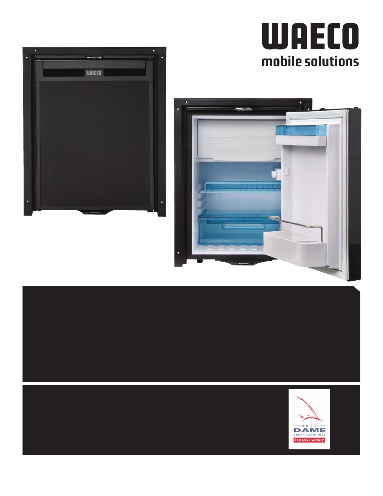
Installing &
Operating Manual
› FRONT LOADING
COMPRESSOR REFRIGERATORS / FREEZERS
CR SERIES
WAECO USA • Clinton, CT • www.waecousa.com
Contents, specifications and availability are subject to change without notice.
Tel. (860) 664-4911 • Fax. (860) 664-4912 • www.waecousa.com
WAECO USA, Inc.
1
Page 2

TABLE OF CONTENTS
Plan for your Installation . . . . . . . . . . . . . . . . . . . . . . . . . . . . . . . . . . . . . . . . 3
Safety Precautions . . . . . . . . . . . . . . . . . . . . . . . . . . . . . . . . . . . . . . . . . . . . . 4
Electrical Requirements . . . . . . . . . . . . . . . . . . . . . . . . . . . . . . . . . . . . . . . . . 5
ABYC Guidelines . . . . . . . . . . . . . . . . . . . . . . . . . . . . . . . . . . . . . . . . . . . . . . 6
Ventilation Requirements . . . . . . . . . . . . . . . . . . . . . . . . . . . . . . . . . . . . . . . 7
Installation . . . . . . . . . . . . . . . . . . . . . . . . . . . . . . . . . . . . . . . . . . . . . . . . 8-10
Changing the Face Panel . . . . . . . . . . . . . . . . . . . . . . . . . . . . . . . . . . . . . . .11
Operation . . . . . . . . . . . . . . . . . . . . . . . . . . . . . . . . . . . . . . . . . . . . . . . . . . 12
Setting the Thermostat . . . . . . . . . . . . . . . . . . . . . . . . . . . . . . . . . . . . . . . . 13
LEDs . . . . . . . . . . . . . . . . . . . . . . . . . . . . . . . . . . . . . . . . . . . . . . . . . . . . . . 13
toc
Troubleshooting . . . . . . . . . . . . . . . . . . . . . . . . . . . . . . . . . . . . . . . . . . . . . . 13
Defrosting . . . . . . . . . . . . . . . . . . . . . . . . . . . . . . . . . . . . . . . . . . . . . . . . . . 14
Cleaning . . . . . . . . . . . . . . . . . . . . . . . . . . . . . . . . . . . . . . . . . . . . . . . . . . . 14
Changing the Lightbulb . . . . . . . . . . . . . . . . . . . . . . . . . . . . . . . . . . . . . . . . 14
Wiring Diagram . . . . . . . . . . . . . . . . . . . . . . . . . . . . . . . . . . . . . . . . . . . . . . 15
Warranty . . . . . . . . . . . . . . . . . . . . . . . . . . . . . . . . . . . . . . . . . . . . . . . . . . . 16
A
US
O
C
AE
W
• P
age
2
Page 3

Thank you for purchasing a WAECO CR series refrigerator. With proper installation,
maintenance, and care your new refrigerator should give you many years of
trouble-free service. WAECO USA would like you to know that, should any
questions or problems arise during installation or operation of your new WAECO
refrigerator, our Technical Support staff is at your service at (860) 664-4911. Our
regular business hours are 8:00AM-5:00PM Eastern Standard (USA) Time.
The WAECO CR series refrigerator should not be modified in any way from its
original form. Modification of the unit may be extremely hazardous and cause
personal injury or property damage.
BEFORE INSTALLATION:
CAREFULLY unpack the box and make sure that your new refrigerator is sitting
upright. Check the packing list and make sure that all parts are included in the
box.
PLAN YOUR INSTALLATION:
There are many variables that make a difference between a good installation
and a problem installation—a refrigerator that will give trouble-free service and
one that will have erratic or short operational life. Many problems that arise with
efrigerators can be traced to improper installation. A little planning can go a
r
long way toward having a reliable source of refrigeration.
ALLATION AND OPERATION MANUAL
AD AND UNDERS
RE
AND THE INS
T
T
COMPLETELY BEFORE ATTEMPTING INSTALLATION.
A
US
O
C
AE
W
• P
age
3
Page 4

CAUTION!!
Hazards associated with working with electricity include electrical shock and
urns. Be extremely careful when working with electricity. Know all hazards
b
involved and observe safe practices to avoid injury.
Be careful when lifting refrigerators. Refrigerators can be heavy objects. Know
how to handle objects of its size and weight and avoid twisting or unusual
positions while supporting it.
Use care when moving and handling the refrigerator. Use gloves to prevent injury
from sharp edges.
Refrigerant lines contain gases. Be very careful when handling. Do not kink,
dent, or bend.
NEVER lift unit by the door or handle.
The refrigerator is not waterproof. Avoid direct contact with water.
Install away from heat sources in a dry and well-ventilated environment.
It is necessary to have a trained technician do the installation in wet areas.
Do not operate the appliance if it is visibly damaged.
DANGER: RISK OF CHILD ENTRAPMENT
Before you throw away your old refrigerator or freezer:
• Take off doors
eave the shelves in place so that children may not easily climb inside.
L
•
A
US
O
C
AE
W
• P
age
4
Page 5

ELECTRICAL REQUIREMENTS
The Danfoss compressor is powered by an internal 12V DC brushless motor. The
C brushless motor operates by a continuous “loop” of information passing
D
between the electronic module and the compressor. Because this operation
requires a “clean” and uninterrupted supply of direct current power, it is
recommended that the refrigerator have a direct connection to the battery.
Wiring it into the fusebox, terminal block, buss bar, or another electrical circuit,
may subject the supply voltage to electrical “noise”, or interference, which may
disrupt the informational loop and render the electronic module inoperative.
Best practice is to wire the unit directly to the battery with an inline fuse on the
positive (+) terminal.
The CR Series refrigerator should be wired on its own circuit. There should be no
other electrical loads on the same circuit. Although 10 amp protection is
sufficient,
The appliance must be wired and grounded in accordance with ABYC guidelines.
Refer to the guidelines on page 5.
Failure to provide a sufficient wire size will result in an unacceptable voltage drop
and inability of the refrigerator to operate.
15 amp is preferable.
A
US
O
C
AE
W
• P
age
5
Page 6

ABYC STANDARD - ABYC GUIDELINES E9 – DIRECT CURRENT
ABYC STANDARD - ABYC GUIDELINES E9 – ALTERNATING CURRENT/AMPERAGE
A
US
O
C
AE
W
• P
age
6
Page 7

VENTILATION REQUIREMENTS
IT IS ABSOLUTELY ESSENTIAL that a refrigerator have adequate
ventilation. It is not possible to have too much ventilation—more
is better. A refrigerator removes heat from the refrigerated space
and gives it off from the coils (condenser) on the back of it. The
heat MUST be removed from the rear of the refrigerator or it
cannot operate correctly.
Inadequate ventilation may lead to premature compressor failure
or inability to cool.
There must be a minimum of 36 square inches of opening to the
outside for ventilation.
wo openings are recommended.
T
Ventilation air must have a clear path in (supply) and a clear path
out (discharge). There must be a minimum of 4” clearance
behind the refrigerator. Use combinations of A1 and A2, B1 and
B2, or C1 and C2 as shown below.
A1
B1
B2
C2
C1
A2
NOTE:
The goal is t
1.
vide as much v
o
o pr
entilation as possible.
ted equal. Vents should be positioned so
a
e
e cr
ents ar
l v
t al
No
2.
that they allow warmer air to escape from the top, and
ooler air entering from the bottom.
y c
ed b
eplac
be r
3. This drawing is not to scale. Vent size is exaggerated
for clarity.
US
O
C
AE
W
A
age
• P
7
Page 8

INSTALLATION
The refrigerator must sit upright for a minimum of 8 hours
prior to installation.
. PREPARE THE SITE
1
The refrigerator should have solid, secure support. Measure
the opening to determine that you have proper clearance for
installation. Do not install in direct sunlight or near a gas stove,
heater, or other heat-generating device. Avoid hot water lines
or warm air ducts.
Make sure that sufficient electrical power is connected per
electrical requirements as outlined. Also be sure that you have
enough length of wire to service the unit outside of the
opening. Ensure that sufficient ventilation is provided per
ventilation requirements. Verify that there is enough room for
the door to swing open with the refrigerator installed.
2. REVERSING THE DOOR SWING.
If the door needs to be reversed, remove the four screws that
hold the top front panel.
Remove the top hinge and panel support by the three screws
that hold them. Lift door off bottom hinge.
Remove the bottom hinge by three screws.
Reinstall the bottom hinge on the opposite side. Install door on
hinge and close door. Reinstall top hinge and panel support on
opposite sides. Reinstall top panel.
3. INSTALL THE FRAME.
Use the screws provided.
A
US
O
C
AE
W
• P
age
8
Page 9

4. MAKE ELECTRICAL CONNECTIONS.
Make sure that polarity (+ and -) is correct on DC circuits.
5. CAREFULLY INSERT UNIT INTO OPENING
until frame is against it.
INSTALLATION
INSERT SCREWS THROUGH SCREW OPENINGS IN FRAME and
6.
screw into cabinet.
A
US
O
C
AE
W
• P
age
9
Page 10

INSTALLATION
. ALLOW REFRIGERATOR TO SIT FOR 1 HOUR BEFORE STARTING.
7
8. START REFRIGERATOR AND CHECK FOR PROPER OPERATION.
If, on the rare chance that your WAECO refrigerator doesn’t
work correctly, verify that the installation was not at fault by
removing refrigerator and allowing it to rest in an open space
for an hour. Connect it directly to a fully charged battery and
turn it on. If the problem persists, contact WAECO at (860)
664-4911 before attempting repair.
AECO cannot be held responsible for any deviation from this set
W
of instructions. We trust that you will enjoy your new WAECO
efrigerator for many years to come.
r
A
US
O
C
AE
W
• P
age
10
Page 11

CHANGING THE FACE PANEL
Unlike most front-loading refrigerators, the CR Series face panel is interchangeable—
while installed in your boat or RV.
1. Remove rubber gasket from the interior door.
2. Unfasten the 4 screws with a Phillips screwdriver.
4. Remove the existing face panel, by sliding it up and out
of the door surround.
{Photo right shows
unit with the face
panel completely
removed.}
3. Remove the door handle by pulling up until the entire
piece is removed.
ed f
err
f
en 4 scr
t
e
ws,
e
5. Slide in pr
e-insert door handle,
R
as
f
-
e
r
apply rubber gasket.
-
e
r
ace panel.
A
US
O
C
AE
W
• P
age
11
Page 12

OPERATION
BEFORE STARTING YOUR NEW REFRIGERATOR:
lean with a mild cleaner to assure cleanliness and proper
1.C
hygiene.
2. Assure that it is only operated within the design parameters.
The design temperature range is 14—110°F (-10—43°C) and
not above 90% relative humidity.
DOOR VENT:
In the VENT position the door will be held open slightly to allow
for air circulation to the inside of the refrigerator. This will help
to inhibit the growth of mold and mildew and avoid odors
A
US
O
C
AE
W
• P
age
12
Page 13

OPERATION
SETTING THE THERMOSTAT:
he thermostat regulates the temperature of the refrigerator. It
T
is calibrated by numbers, “1” being the warmest setting and “7”
eing the coldest setting.
b
Start with the thermostat at a setting midway between the
warmest and coldest setting. After unit has reached a steadystate temperature, adjust as necessary to maintain desired
temperature. Do not make large adjustments. Adjust by small
increments and let cool before readjusting.
Understand that, should you load your refrigerator excessively
with warm food, it may take a very long tome to cool down. To
avoid this “hot pull-down” condition, pre-cool food, or add only
small amounts of warm food at a time. This will avoid
unnecessary work by the cooling system and save on your
energy usage.
LED:
There are TWO LED’S next to the thermostat. One is green during
normal operation. The other flashes a specific number of times
in sequence to indicate a problem that prevents operation. The
number of flashes in a row indicate the fault.
TROUBLESHOOTING LED FLASHES
NUMBER
1 Supply Voltage The supply voltage is outside of the set range.
2 Excessive Fan Current The fan loads the electronics unit with more than 1A.
3 Motor does not Start The rotor is jammed.
4 Speed too Low If the cooling system overloaded, the minimum speed of the
5 Ov
OF FLASHES FAULT POSSIBLE CAUSE
The pressure difference in the cooling system, is too high.
(> 5 bar)
f 1850 RPM can not be maintained.
or o
t
mo
ting of the Electronics Unit If the cooling system is loaded too heavily or the
a
erhe
temperature is set too high, the electronics can overheat.
A
US
O
C
AE
W
• P
age
13
Page 14

OPERATION
DEFROSTING THE REFRIGERATOR:
he CR series refrigerator is not frost-free. When operating over
T
a period of time, the freezer will build-up with ice and requires
eriodic defrosting. Failure to defrost the refrigerator will result
p
in an excessive build-up of ice and a reduced ability to absorb
heat (cool).
Shut off the power at the thermostat and open the door to allow
warm ambient air to melt the ice.
DO NOT add heat to speed defrost as this may distort
components of the refrigerator.
Gather the water in the drip pan, located at the rear bottom of
the unit. Empty pan when full. Alternatively, the drip pan can be
removed and a drain hose connected to the drain (underneath
the rear of the unit) to drain the water.
CLEANING:
Should your refrigerator become dirty, clean with a clean, damp
cloth.
1. DRIP PAN
DO NOT use abrasive cleaners or cleansers as these can damage
the refrigerator.
DO NOT allow electronic components to get wet.
DO NOT use sharp objects or scrapers to loosen stuck objects or
ice.
CHANGING THE LIGHT BULB
urn off power to the unit.
T
:
Pull off the light bulb cover, located behind the thermostat inside
the unit.
emove the light bulb from the two prongs at each end of the
R
.
b
bul
Replace with a new bulb by pushing each end of the bulb
between the two prongs. Snap cover back into place.
A
US
O
C
AE
W
• P
age
14
Page 15

WIRING DIAGRAM
wing diagrams, depending on the compressor
lo
ol
A
US
O
C
AE
the f
The CR Refrigerator/Freezer is wired according to one of
module number located on the face of the module.
W
• P
age
15
Page 16

IMPORTANT INFORMATION • LIMITED WARRANTY
WAECO USA LIMITED WARRANTY
AECO USA, Inc. warrants its products to be
W
free of defects in materials and workmanship
for the periods specified below subject to the
specified conditions and limitations.
WAECO Will Do:
emedy at Company's discretion) goods or parts
r
that prove to be defective in materials or workmanship after examination by a factory representative or authorized service dealer.
How long Coverage Lasts: COMPRESSOR
PRODUCTS
Labor:
from an authorized service agent for one
year from date of purchase or third party
installation. For OEM factory installed products the duration is one year from the date
of purchase of the vehicle (vessel).
Repair or replace (choice of
WAECO will pay for necessary labor
What
Parts:
WAECO will pay for necessary parts for
two years from the date of purchase or third
party installation. For OEM factory installed products the duration is two years from the date of
purchase of the vehicle (vessel).
What is Not Covered:
1. Damages due to accident, misuse, abuse,
normal wear, improper installation, lack of
easonable and necessary maintenance,
r
transportation, corrosion, tampering,
improper repair, unusual physical or electrical stress or recharging of the coolant.
2. Electric light bulbs or replaceable fuses.
3. Failures due to use of the products in
applications for which they are not intended.
4. Warranty coverage following unauthorized
service.
5. Warranty coverage following transfer of
ownership.
How State Law Relates to this Warranty:
This warranty gives you specific legal rights,
and you also have other rights, which vary from
State to State.
THERE ARE NO OTHER WARRANTIES OF
MERCHANTABILITY, FITNESS FOR PURPOSE OR
ANY OTHER KIND. ANY EXPRESSED OR IMPLIED
ARE HEREBY DISCLAIMED AND EXCLUDED. THE
COMPANY SHALL NOT BE LIABLE FOR CONSEQUENTIAL DAMAGES TO YACHTS, EQUIPMENT OR
OTHER PROPERTY OR PERSONS DUE TO ANY FAILURE OF WAECO USA PRODUCTS. THIS WARRANTY
S EXPRESSLY PROVIDED IN LIEU OF ALL OTHER
I
WARRANTIES EITHER EXPRESSED OR IMPLIED.
A
US
O
C
AE
W
• P
age
16
 Loading...