

Page 1
Operator’s Manual
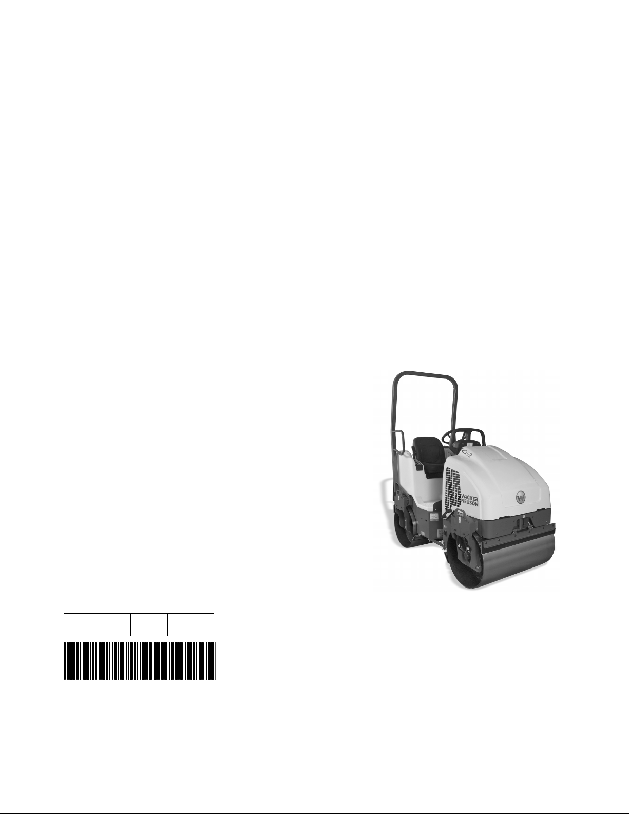
Roller
RD 12A
0182863en 001 0610
0182863EN
Page 2

Copyright
notice
© Copyright 2010 by Wacker Neuson Corporation.
All rights, including copying and distribution rights, are reserved.
This publication may be photocopied by the original purchaser of the machine. Any
other type of reproduction is prohibited without express written permission from
Wacker Neuson Corporation.
Any type of reproduction or distribution not authorized by Wacker Neuson Corporation
represents an infringement of valid copyrights. Violators will be prosecuted.
Trademarks
Manufacturer
All trademarks referenced in this manual are the property of their respective owners.
Wacker Neuson Corporation
N92W15000 Anthony Avenue
Menomonee Falls, WI 53051 U.S.A.
Tel: (262) 255-0500 · Fax: (262) 255-0550 · Tel: (800) 770-0957
www.wackerneuson.com
Original
instructions
This Operator’s Manual presents the original instructions. The original language of this
Operator’s Manual is American English.
Page 3

Foreword
Machines
covered in
this manual
Foreword
Machine Item Number
RD 12A 0620058, rev 211 and higher
0620320, rev 211 and higher
0620369, rev 211 and higher
Machine
documentation
Expectations
for
information in
this manual
Keep a copy of the Operator’s Manual with the machine at all times.
Use the separate Parts Book supplied with the machine to order replacement
parts.
Refer to the separate Repair Manual for detailed instructions on servicing and
repairing the machine.
If you are missing any of these documents, please contact Wacker Neuson
Corporation to order a replacement or visit www.wackerneuson.com.
When ordering parts or requesting service information, be prepared to provide
the machine model number, item number, revision number, and serial number.
This manual provides information and procedures to safely operate and
maintain the above Wacker Neuson model(s). For your own safety and to
reduce the risk of injury, carefully read, understand, and observe all instructions
described in this manual.
Wacker Neuson Corporation expressly reserves the right to make technical
modifications, even without notice, which improve the performance or safety
standards of its machines.
The information contained in this manual is based on machines manufactured
up until the time of publication. Wacker Neuson Corporation reserves the right
to change any portion of this information without notice.
CALIFORNIA
Proposition
65 Warning
Laws
pertaining to
spark
arresters
Engine exhaust, some of its constituents, and certain vehicle components, contain
or emit chemicals known to the State of California to cause cancer and birth
defects or other reproductive harm.
NOTICE: State Health Safety Codes and Public Resources Codes specify that in
certain locations spark arresters be used on internal combustion engines that use
hydrocarbon fuels. A spark arrester is a device designed to prevent accidental discharge of sparks or flames from the engine exhaust. Spark arresters are qualified
and rated by the United States Forest Service for this purpose. In order to comply
with local laws regarding spark arresters, consult the engine distributor or the local
Health and Safety Administrator.
Manufacturer’s
approval
This manual contains references to approved parts, attachments, and
modifications. The following definitions apply:
Approved parts or attachments are those either manufactured or provided by
Wacker Neuson.
Approved modifications are those performed by an authorized Wacker
Neuson service center according to written instructions published by Wacker
Neuson.
wc_tx001555gb.fm 3
Page 4

Foreword
Unapproved parts, attachments, and modifications are those that do not
meet the approved criteria.
Unapproved parts, attachments, or modifications may have the following
consequences:
Serious injury hazards to the operator and persons in the work area
Permanent damage to the machine which will not be covered under warranty
Contact your Wacker Neuson dealer immediately if you have questions about
approved or unapproved parts, attachments, or modifications.
4 wc_tx001555gb.fm
Page 5

RD 12A Table of Contents
Foreword 3
1 Safety Information 9
1.1 Signal Words Used in this Manual ....................................................... 9
1.2 Machine Description and Intended Use ............................................. 10
1.3 Operator Safety while Using Internal Combustion Engines ............... 13
1.4 Service Safety ................................................................................... 14
2 Labels 16
2.1 Label Locations .................................................................................. 16
2.2 Label Meanings .................................................................................. 17
3 Lifting and Transporting 21
3.1 Lifting the Machine ............................................................................. 21
3.2 Tying Down and Transporting the Machine ........................................ 22
4 Operation 24
4.1 Features and Controls ........................................................................ 24
4.2 Control Panel ...................................................................................... 26
4.3 Preparing the Machine for First Use ................................................... 27
4.4 Position of the Operator ..................................................................... 27
4.5 Recommended Fuel ........................................................................... 27
4.6 Roll Over Protection Structure (ROPS) .............................................. 28
4.7 Foldable Roll Over Protection Structure (ROPS) (if equipped) .......... 29
4.8 Rotating Beacon (if equipped) ............................................................ 30
4.9 Backup Alarm (if equipped) ................................................................ 30
4.10 Lighting Equipment (if equipped) ........................................................ 31
4.11 Seat Belt ............................................................................................. 31
4.12 Operator Presence System ................................................................ 32
4.13 Scraper Bars ...................................................................................... 33
4.14 Anti-Vandalism Protection and Machine Access ................................ 34
4.15 Articulation Joint Lockarm .................................................................. 35
wc_bo0182863en_001TOC.fm 5
Page 6

Table of Contents RD 12A
4.16 Machine Stability .................................................................................36
4.17 Before Starting ....................................................................................37
4.18 Starting ................................................................................................38
4.19 Stopping/Parking .................................................................................41
4.20 Emergency Shutdown Procedure ........................................................42
4.21 Parking Brake ......................................................................................43
4.22 Parking Brake Adjustment ...................................................................44
4.23 Direction and Speed ............................................................................45
4.24 Transmission .......................................................................................46
4.25 Vibration ..............................................................................................47
4.26 Water Spray System ...........................................................................48
4.27 Auxiliary Battery Positive Terminal ......................................................49
4.28 Panel Indicator Lights ..........................................................................50
4.29 Adding Ballast to Rear Drum ...............................................................51
5 Maintenance 52
5.1 Engine Maintenance Schedule ............................................................52
5.2 Roller Maintenance Schedule .............................................................53
5.3 Rear Frame Access .............................................................................54
5.4 Battery .................................................................................................55
5.5 Fuel Filter ............................................................................................57
5.6 Engine Oil and Filter ............................................................................58
5.7 Spark Plug ...........................................................................................59
5.8 Engine Air Cleaner ..............................................................................60
5.9 Grease Fittings ....................................................................................61
5.10 Hydraulic System Cleanliness .............................................................62
5.11 Hydraulic Oil Requirements .................................................................63
5.12 Hydraulic Oil Level ..............................................................................64
5.13 Hydraulic Suction Strainer ...................................................................64
5.14 Changing the Hydraulic Oil & Filter .....................................................65
5.15 Bleeding the Hydraulic System ...........................................................65
5.16 Long-Term Storage .............................................................................65
5.17 Towing Bypass Valve ..........................................................................67
5.18 Towing .................................................................................................68
6 Basic Troubleshooting 70
6 wc_bo0182863en_001TOC.fm
Page 7

RD 12A Table of Contents
7 Schematics 71
7.1 Electrical Schematic ........................................................................... 71
7.2 Electrical Schematic Components ...................................................... 72
7.3 Hydraulic Schematic ........................................................................... 73
7.4 Hydraulic Schematic Components ..................................................... 73
8 Technical Data 75
8.1 Engine ................................................................................................ 75
8.2 Roller .................................................................................................. 76
8.3 Lubrication .......................................................................................... 76
8.4 Dimensions ......................................................................................... 77
8.5 Sound Measurements ........................................................................ 77
8.6 Vibration Measurements .................................................................... 78
8.7 Hydraulic Pressures ........................................................................... 78
wc_bo0182863en_001TOC.fm 7
Page 8

Table of Contents RD 12A
8 wc_bo0182863en_001TOC.fm
Page 9

RD 12A Safety Information
1 Safety Information
1.1 Signal Words Used in this Manual
This manual contains DANGER, WARNING, CAUTION, NOTICE, and
NOTE signal words which must be followed to reduce the possibility
of personal injury, damage to the equipment, or improper service.
This is the safety alert symbol. It is used to alert you to potential personal hazards.
f Obey all safety messages that follow this symbol.
DANGER
DANGER indicates a hazardous situation which, if not avoided, will result in death
or serious injury.
f
To avoid death or serious injury from this type of hazard, obey all safety messages that
follow this signal word.
WARNING
WARNING indicates a hazardous situation which, if not avoided, could result in
death or serious injury.
To avoid possible death or serious injury from this type of hazard, obey all safety mes-
f
sages that follow this signal word.
CAUTION!
CAUTION indicates a hazardous situation which, if not avoided, could result in
minor or moderate injury.
f
To avoid possible minor or moderate injury from this type of hazard, obey all safety messages that follow this signal word.
NOTICE: Used without the safety alert symbol, NOTICE indicates a
situation which, if not avoided, could result in property damage.
Note: A Note contains additional information important to a procedure.
wc_si000516gb.fm 9
Page 10

Safety Information RD 12A
1.2 Machine Description and Intended Use
This machine is a dual drum, ride-on roller. The Wacker Neuson RideOn Roller consists of an articulated frame onto which is mounted a
gasoline or diesel engine, a fuel tank, a hydraulic tank, a water tank, a
hydrostatic drive system, two steel drums containing internal eccentric
weights, and an operator’s platform with a ROPS (Roll Over Protective
Structure). The engine powers the hydraulic systems that provide
machine movement and drum vibration. The vibrating drums smooth
and compact the work surface as the machine moves. Machine speed,
direction, and vibration are controlled by the operator from the
operator’s seat on the platform.
The machine is designed as a lightweight roller to be used in the
compaction of sublayers and finish layers of asphalt on roads,
driveways, parking lots, and other types of asphalt-covered surfaces.
This machine has been designed and built strictly for the intended use
described above. Using the machine for any other purpose could
permanently damage the machine or seriously injure the operator or
other persons in the area. Machine damage caused by misuse is not
covered under warranty.
The following are some examples of misuse:
• Using the machine as a ladder, support, or work surface
• Using the machine to carry or transport passengers or equipment
• Using the machine to tow other machines
• Using the machine to spray liquids other than water (i.e., diesel
fuel on asphalt)
• Operating the machine outside of factory specifications.
• Operating the machine in a manner inconsistent with all warnings
found on the machine and in the Operator’s Manual.
This machine has been designed and built in accordance with the
latest global safety standards. It has been carefully engineered to
eliminate hazards as far as practicable and to increase operator
safety through protective guards and labeling. However, some risks
may remain even after protective measures have been taken. They
are called residual risks. On this machine, they may include exposure
to:
• Heat, noise, exhaust, and carbon monoxide from the engine
• Burns from hot hydraulic fluid
• Fire hazards from improper refueling techniques
• Fuel and its fumes
• Personal injury from improper lifting techniques
10 wc_si000516gb.fm
Page 11

RD 12A Safety Information
• Crushing hazards from improper operation (feet, legs, or arms
extending outside of the operator work station) and for other
persons in the work zone
• Line of sight blockage by the ROPS
To protect yourself and others, make sure you thoroughly read and
understand the safety information presented in this manual before
operating the machine.
Safety Guidelines for Operating the Machine
Familiarity and proper training are required for the safe operation of the
machine. Machines operated improperly or by untrained personnel
can be hazardous. Read the operating instructions contained in this
WARNING
Operator qualifications
manual and the engine manual, and familiarize yourself with the
location and proper use of all controls. Inexperienced operators should
receive instruction from someone familiar with the machine before
being allowed to operate it.
Only trained personnel are permitted to start, operate, and shut down
the machine. They also must meet the following qualifications:
• have received instruction on how to properly use the machine
• are familiar with required safety devices
The machine must not be accessed or operated by:
•children
• people impaired by alcohol or drugs
Personal Protective Equipment (PPE)
Wear the following Personal Protective Equipment (PPE) while
operating this machine:
• Close-fitting work clothes that do not hinder movement
• Safety glasses with side shields
• Hearing protection
• Safety-toed footwear
1.2.1
DO NOT drive over curbs or other uneven objects that will result in the
machine and operator being shaken.
1.2.2 DO NOT attempt to start the machine when standing alongside it. Only
start the engine when seated in the driver's seat and with the forward/
reverse control in the neutral position.
1.2.3 Do not allow anyone to operate this equipment without proper training.
People operating this equipment must be familiar with the risks and
hazards associated with it.
1.2.4 Do not touch the engine or muffler while the engine is on or immediately
after it has been turned off. These areas get hot and may cause burns.
wc_si000516gb.fm 11
Page 12

Safety Information RD 12A
1.2.5 Do not use accessories or attachments that are not recommended by
Wacker Neuson. Damage to equipment and injury to the user may result.
1.2.6 Never leave the machine running unattended.
1.2.7 NEVER operate the machine with the fuel cap loose or missing.
1.2.8 NEVER carry passengers on the machine. Crushing hazard—keep clear
of the articulated steering joint between the front and rear frames.
1.2.9 NEVER use or attempt to repair damaged safety belts or ROPS. Replace
only with Wacker Neuson spare parts.
1.2.10 ALWAYS disengage and stow the locking bar for the articulated steering
joint before operating the machine. The machine cannot be steered when
the locking bar is engaged.
1.2.11 ALWAYS check that all controls are functioning properly immediately after
start-up! DO NOT operate the machine unless all controls operate
correctly.
1.2.12 ALWAYS remain aware of changing positions and the movement of other
equipment and personnel on the job site.
1.2.13 Always remain seated and wear the seat belt at all times while operating
the machine.
1.2.14 ALWAYS remain aware of changing surface conditions and use extra care
when operating over uneven ground, on hills, or over soft or coarse
material. The machine could shift or slide unexpectedly.
1.2.15 ALWAYS use caution when operating the machine near the edges of pits,
trenches or platforms. Check to be sure that ground surface is stable
enough to support the weight of the machine with operator and that there
is no danger of the roller sliding, falling or tipping.
1.2.16 Always wear protective clothing appropriate to the job site when operating
the machine.
1.2.17 Always keep hands, feet, and loose clothing away from moving parts of the
machine.
1.2.18 Read, understand, and follow procedures in the Operator’s Manual before
attempting to operate the machine.
1.2.19 Store the machine properly when it is not being used. The machine should
be stored in a clean, dry location out of the reach of children.
1.2.20 Always operate the machine with all safety devices and guards in place
and in working order.
1.2.21 Make sure that all other persons are at a safe distance from the machine.
Stop the machine if people step into the working area of the machine.
1.2.22 Do not use a cellphone or send text messages while operating this
machine.
12 wc_si000516gb.fm
Page 13

RD 12A Safety Information
1.3 Operator Safety while Using Internal Combustion Engines
WARNING
Internal combustion engines present special hazards during operation and fueling. Failure to
follow the warnings and safety standards could result in severe injury or death.
f Read and follow the warning instructions in the engine owner’s manual and the
safety guidelines below.
DANGER
Exhaust gas from the engine contains carbon monoxide, a deadly poison. Exposure to carbon monoxide can kill you in minutes.
f NEVER operate the machine inside an enclosed area, such as a tunnel, unless
adequate ventilation is provided through such items as exhaust fans or hoses.
Operating safety
When running the engine:
• Keep the area around exhaust pipe free of flammable materials.
• Check the fuel lines and the fuel tank for leaks and cracks before starting
the engine. Do not run the machine if fuel leaks are present or the fuel
lines are loose.
When running the engine:
• Do not smoke while operating the machine.
• Do not run the engine near sparks or open flames.
• Do not touch the engine or muffler while the engine is running or
immediately after it has been turned off.
• Do not operate a machine when its fuel cap is loose or missing.
• Do not start the engine if fuel has spilled or a fuel odor is present. Move
the machine away from the spill and wipe the machine dry before
starting.
Refueling safety
When refueling the engine:
• Clean up any spilled fuel immediately.
• Refill the fuel tank in a well-ventilated area.
• Replace the fuel tank cap after refueling.
• Do not smoke.
• Do not refuel a hot or running engine.
• Do not refuel the engine near sparks or open flames.
• Do not refuel if the machine is positioned in a truck fitted with a plastic
bed liner. Static electricity can ignite the fuel or fuel vapors.
wc_si000516gb.fm 13
Page 14

Safety Information RD 12A
1.4 Service Safety
A poorly maintained machine can become a safety hazard! In order
for the machine to operate safely and properly over a long period of
time, periodic maintenance and occasional repairs are necessary.
WARNING
Personal Protective Equipment (PPE)
Wear the following Personal Protective Equipment (PPE) while servicing
or maintaining this machine:
• Close-fitting work clothes that do not hinder movement
• Safety glasses with side shields
• Hearing protection
• Safety-toed footwear
In addition, before servicing or maintaining the machine:
• Tie back long hair.
• Remove all jewelry (including rings).
1.4.1 Some service procedures require that the machine’s battery be
disconnected. To reduce the risk of personal injury, read and understand
the service procedures before performing any service to the machine.
1.4.2 All adjustments and repairs MUST be completed before operation. Do not
operate the machine with a known problem or deficiency! All repairs and
adjustments should be completed by a qualified technician.
1.4.3 Do not attempt to clean or service the machine while it is running. Rotating
parts can cause severe injury.
1.4.4 Do not crank a flooded engine with the spark plug removed on gasolinepowered engines. Fuel trapped in the cylinder will squirt out the spark plug
opening.
1.4.5 Do not test for spark on gasoline-powered engines if the engine is flooded
or the smell of gasoline is present. A stray spark could ignite the fumes.
1.4.6 Do not use gasoline or other types of fuels or flammable solvents to clean
parts, especially in enclosed areas. Fumes from fuels and solvents can
become explosive.
1.4.7 Do not modify the machine without the express written approval of the
manufacturer.
1.4.8 DO NOT stand under the machine while it is being hoisted or moved.
1.4.9 DO NOT get onto the machine while it is being hoisted or moved.
1.4.10 DO NOT use the machine as a ladder. Use safe ladders and platforms
designed for this purpose.
1.4.11 DO NOT modify, weld, or drill safety frames (ROPS) fitted as original
equipment. DO NOT loosen or remove bolts. DO NOT weld, drill or modify
a broken safety frame.
14 wc_si000516gb.fm
Page 15

RD 12A Safety Information
1.4.12 DO NOT open the hydraulic lines or loosen the hydraulic connections
while the engine is running! Before dismantling the hydraulic connectors
or hoses, ensure that all pressure has been bled from the circuit. Hydraulic
fluid under pressure can penetrate the skin, cause burns, blind, or create
other personal injury hazards. Set all controls in neutral, turn engine off,
and allow the fluids to cool before loosening hydraulic fittings or attaching
test gauges.
1.4.13 ALWAYS check all external fasteners at regular intervals.
1.4.14 Keep the area around the muffler free of debris such as leaves, paper,
cartons, etc. A hot muffler could ignite the debris and start a fire.
When replacement parts are required for this machine, use only Wacker
Neuson replacement parts or those parts equivalent to the original in all
types of specifications, such as physical dimensions, type, strength, and
material.
1.4.15 Disconnect the spark plug on machines equipped with gasoline engines,
before servicing, to avoid accidental start-up.
1.4.16 Keep the machine clean and labels legible. Replace all missing and hardto-read labels. Labels provide important operating instructions and warn of
dangers and hazards.
1.4.17 ALWAYS do periodic maintenance as recommended in the Operator’s
Manual.
1.4.18 ALWAYS turn the engine off before performing maintenance or making
repairs.
1.4.19 ALWAYS keep hands, feet and loose clothing away from moving parts.
1.4.20 ALWAYS make sure slings, chains, hooks, ramps, jacks, and other types
of lifting devices are attached securely and have enough weight-bearing
capacity to lift or hold the machine safely. Always remain aware of the
location of other people in the area when lifting the machine.
1.4.21 Always make sure hose connections have been reconnected back to the
correct fitting. Failure to do so may result in damage to the machine and/
or injury to person on or near the machine.
1.4.22 ALWAYS secure the articulated steering joint using the locking bar before
lifting, jacking, and servicing the machine. The machine halves could
swing together unexpectedly and cause a serious injury.
1.4.23 ALWAYS lock the lifting cylinders in the open position when the seat
pedestal is raised.
1.4.24 Before you start the machine, ensure that all tools have been removed
from the machine and that replacement parts and adjusters are firmly
tightened.
1.4.25 Fluid leaks from small holes are often practically invisible. DO NOT use
your bare hands to check for leaks. Check for leaks using a piece of
cardboard or wood.
wc_si000516gb.fm 15
Page 16
Labels RD 12A
2Labels
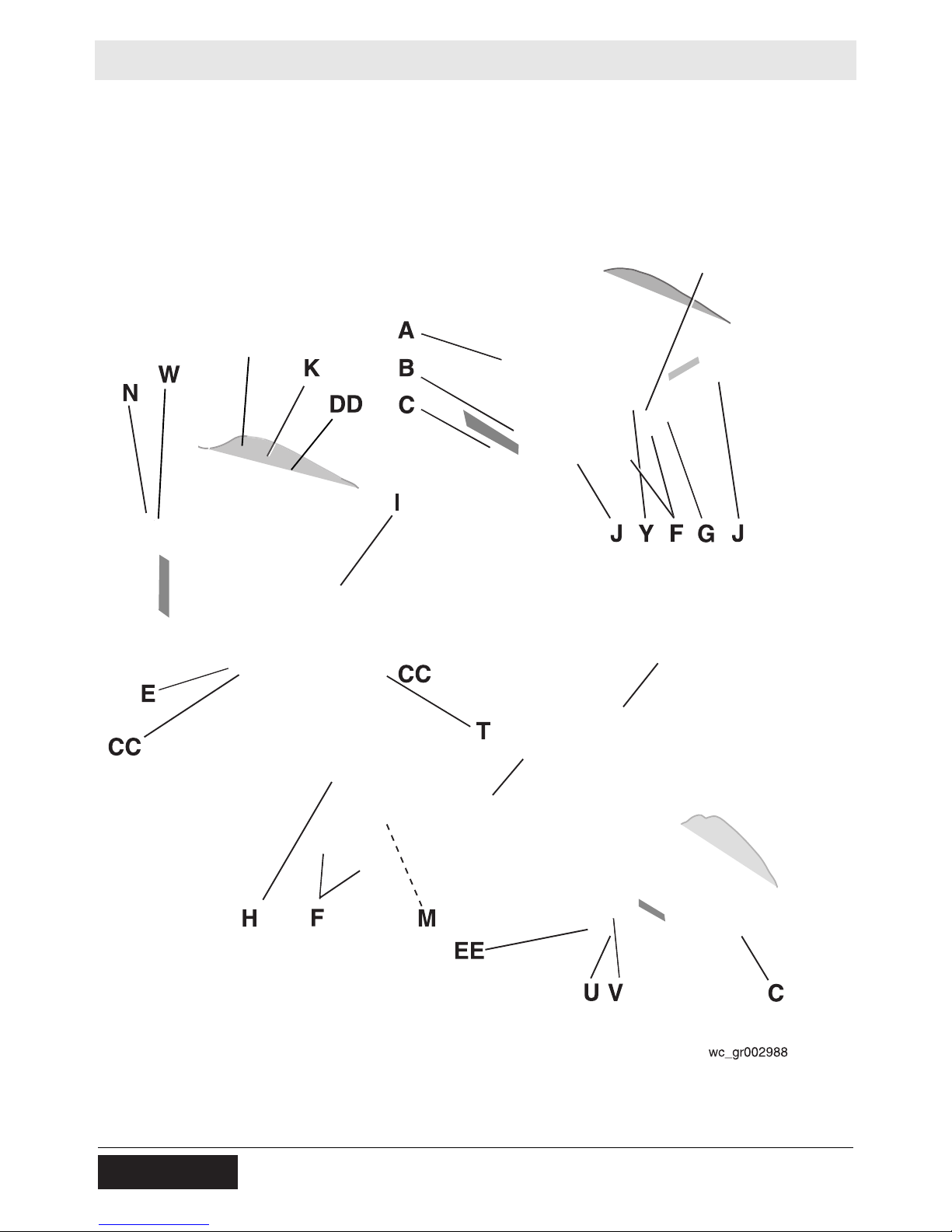
2.1 Label Locations
FF
X
GG
GG
16 wc_si000302gb.fm
Page 17
RD 12A Labels
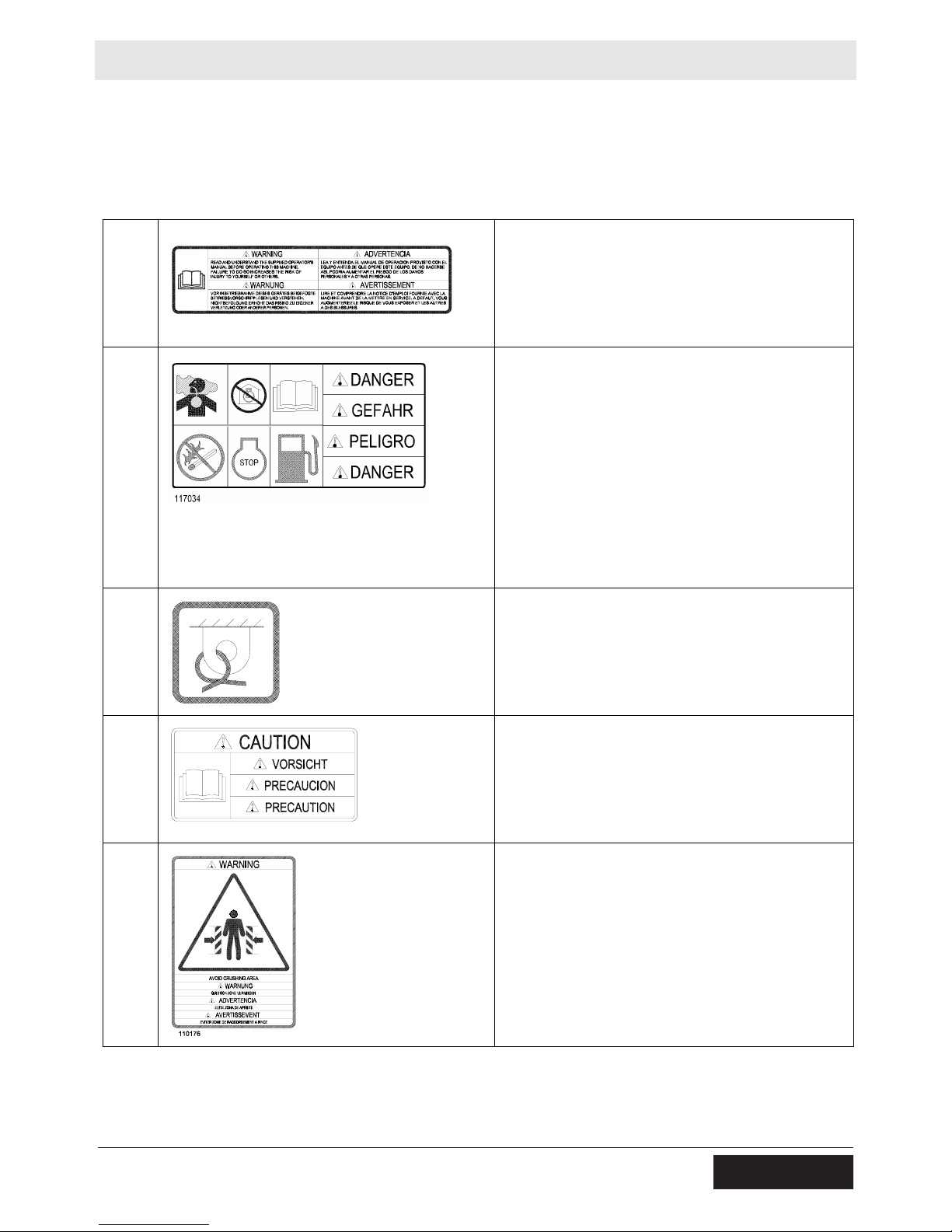
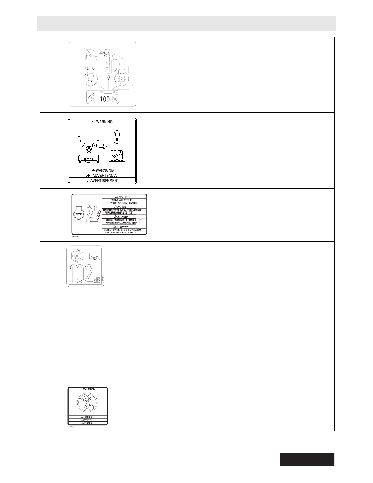
2.2 Label Meanings
Wacker Neuson machines use international pictorial labels where
needed. These labels are described below.
A
B
C
WARNING!
Read and understand the supplied Operator’s
Manual before operating the machine. Failure to
do so increases the risk of injury to yourself and
others.
DANGER!
Asphyxiation hazard.
Engines emit carbon monoxide.
Do not run the machine indoors or in an
enclosed area unless adequate ventilation,
through such items as exhaust fans or hoses,
is provided.
Read the Operator’s Manual. No sparks,
flames, or burning objects near the machine.
Stop the engine before refueling.
Tie-down point.
E
F
wc_si000302gb.fm 17
CAUTION!
Read and understand the supplied Operator’s
Manual before operating this machine. Failure to
do so increases the risk of injury to yourself and
others.
WARNING!
Pinch point.
Page 18
Labels RD 12A
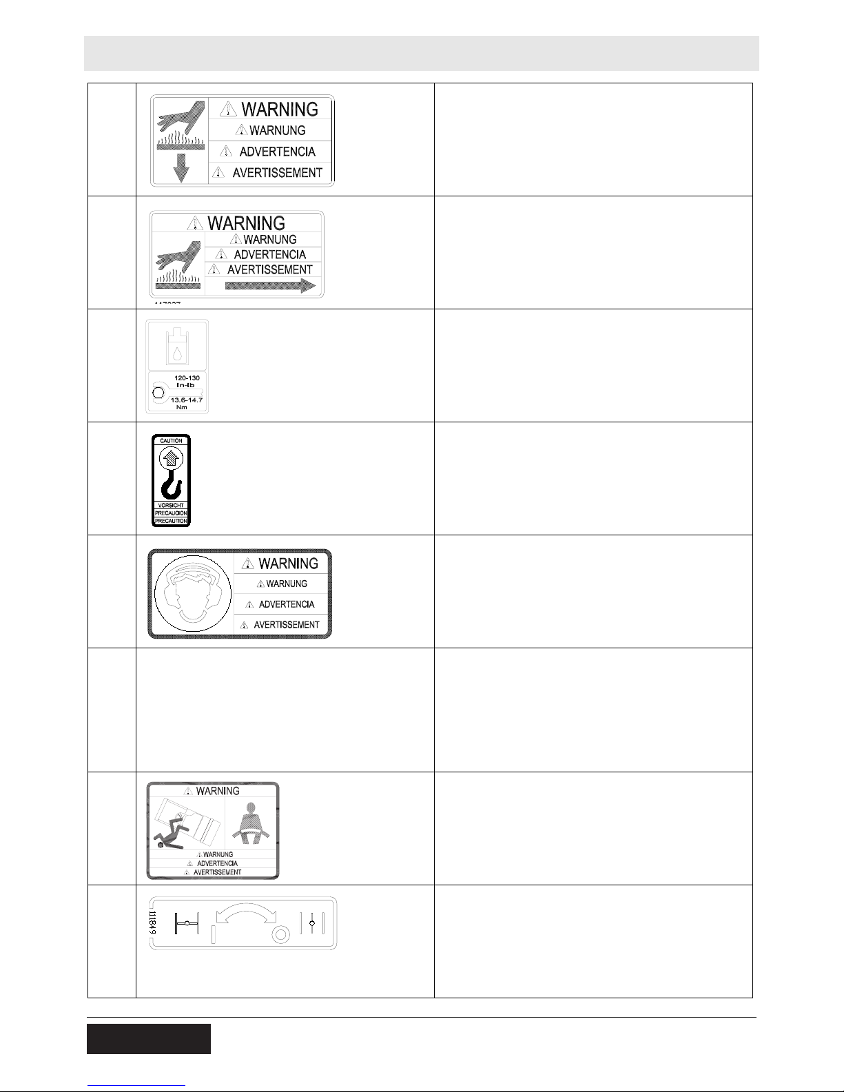
G
H
I
WARNING!
Hot surface!
WARNING!
Hot surface!
Hydraulic oil reservoir fill tube.
Torque nuts to 13.6-14.7 Nm (120-130 in.lbs.)
maximum.
J CAUTION
Lifting point.
K
WARNING!
To prevent hearing loss, wear hearing protection
when operating this machine.
M WARNING!
Disconnect battery before servicing.
Read Repair Manual for instructions.
Battery contains caustic acid and
potentially explosive hydrogen gas.
N
T
WARNING!
Always wear seat belt when operating roller.
Choke:
0 = Open
l = Closed
18 wc_si000302gb.fm
Page 19
RD 12A Labels
U
V
W
Grease points: Inspect and lubricate every 100
hours of operation.
WARNING!
Avoid crushing area.
Articulated steering joint locking location. Lock
the articulated steering joint before servicing the
machine.
Read Repair Manual.
Engine will stop without operator seated.
X
Y
Z
Guaranteed sound power level in dB(A).
A nameplate listing the model number, item
number, revision number, and serial number is
attached to each unit. Please record the
information found on this plate so it will be
available should the nameplate become lost or
damaged. When ordering parts or requesting
service information, you will always be asked to
specify the model number, item number, revision
number, and serial number of the unit.
No lift point.
wc_si000302gb.fm 19
Page 20
Labels RD 12A
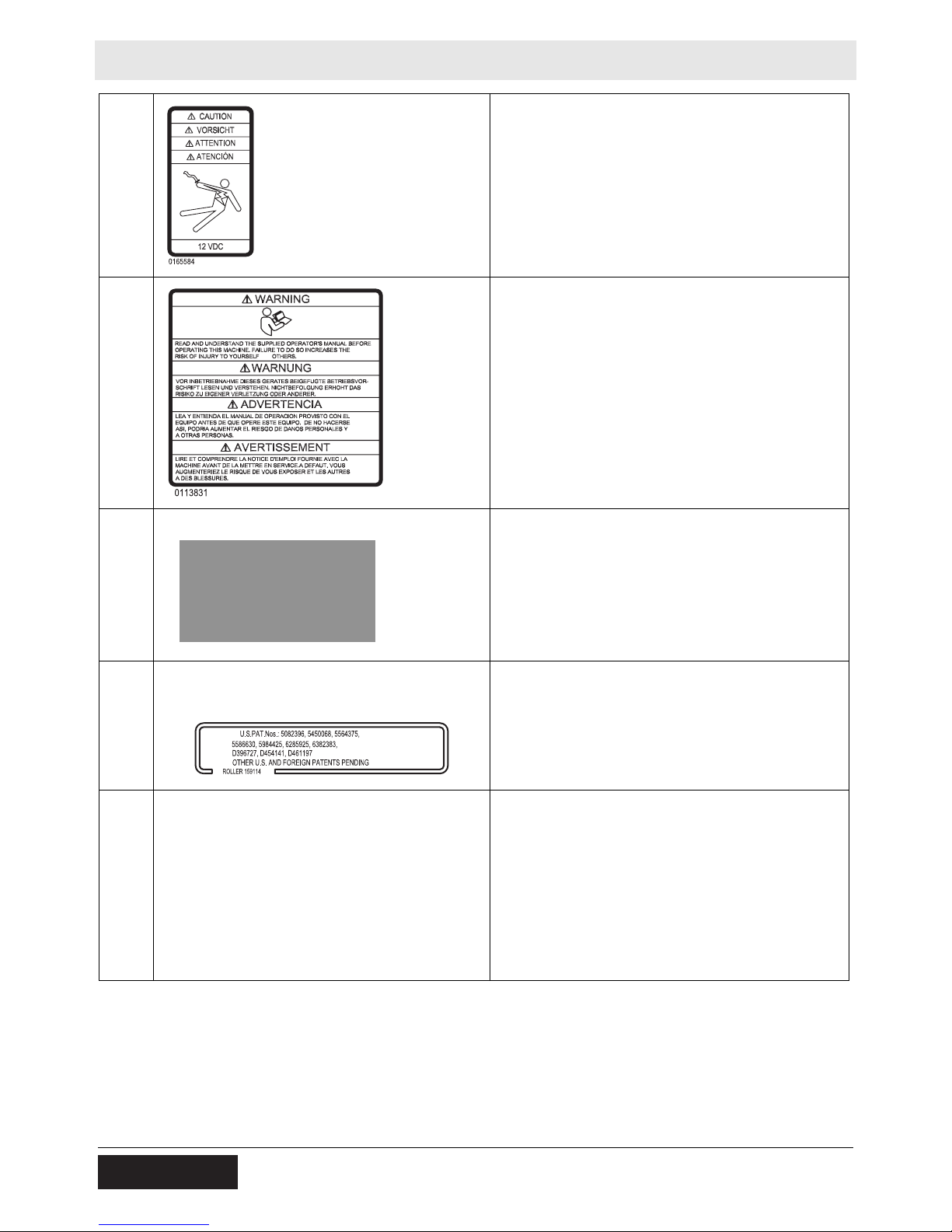
CC CAUTION! Electric shock hazard at
auxiliary battery positive terminal. Never
touch this terminal and a metal portion of
the machine simultaneously.
DD
EE
FF
WARNING!
Read and understand the supplied Operator’s
Manual before operating the machine. Failure to
AND
do so increases the risk of injury to yourself and
others.
Water tank fill.
This machine may be covered by one or more
patents.
GG
WARNING!
Avoid crushing area.
20 wc_si000302gb.fm
Page 21

RD 12A Lifting and Transporting
3 Lifting and Transporting
3.1 Lifting the Machine
See Graphic: wc_gr003454
Stop the engine.
Locking the articulated joint lockarm (a)
Before lifting the machine, make sure the articulated joint lockarm is in
the LOCKED position. Refer to section Articulation Joint Lockarm for
information.
Lifting
Use lifting ropes or chains with an appropriate amount of load bearing
capacity. Attach the lifting ropes to the lifting eyes (b) on the machine
using hooks or shackles. Attach the other end of the ropes to the hook
of the lifting equipment. The hook must have a lifting capacity which
will support the weight of the machine. Refer to section Technical Data
for weight information. Lift the machine using four ropes, one rope
attached to each lifting eye and a spreader bar that prevents the ropes
from contacting the machine.
WARNING
Crushing / machine damage hazards. Use only steel ropes or chains
for lifting. Ropes or chains must have the suitable specified lifting
capacity and must be at least 2000 mm (6.5 ft.) long. Do not use
improvised ropes or chains.
Do not stand under, or get onto, the machine while it is being lifted or
moved.
b
b
wc_tx001556gb.fm 21
a
wc_gr003454
Page 22

Lifting and Transporting RD 12A
3.2 Tying Down and Transporting the Machine
See Graphic: wc_gr003455
Lock the articulated joint lockarm. Refer to section Articulation Joint
Lockarm for information.
When transporting the machine, place blocks in front of and behind
each drum and use the front and rear tie-down points (a) provided to
securely fasten the machine to the trailer (two places). Secure the
machine by attaching steel ropes or chains to the tie down points (a).
Note: The transmission is normally braked when the engine is off, or
when the hydraulic system is not functioning, unless there is a fault
and/or the parking brakes have been manually disabled.
NOTICE: Do not position ropes or chains across the machine frame or
the articulated joint when tying down the machine. Damage to the
machine may occur.
NOTICE: Do not use complete deflection of shock mounts when tying
down the machine. Damage to the shock mounts may occur.
NOTICE: Do not leave the machine tied down for extended periods of
time (except when transporting the machine). Damage to the shock
mounts may occur.
a a
wc_gr003455
22 wc_tx001556gb.fm
Page 23

RD 12A Lifting and Transporting
Notes:
wc_tx001556gb.fm 23
Page 24

Operation RD 12A
4 Operation
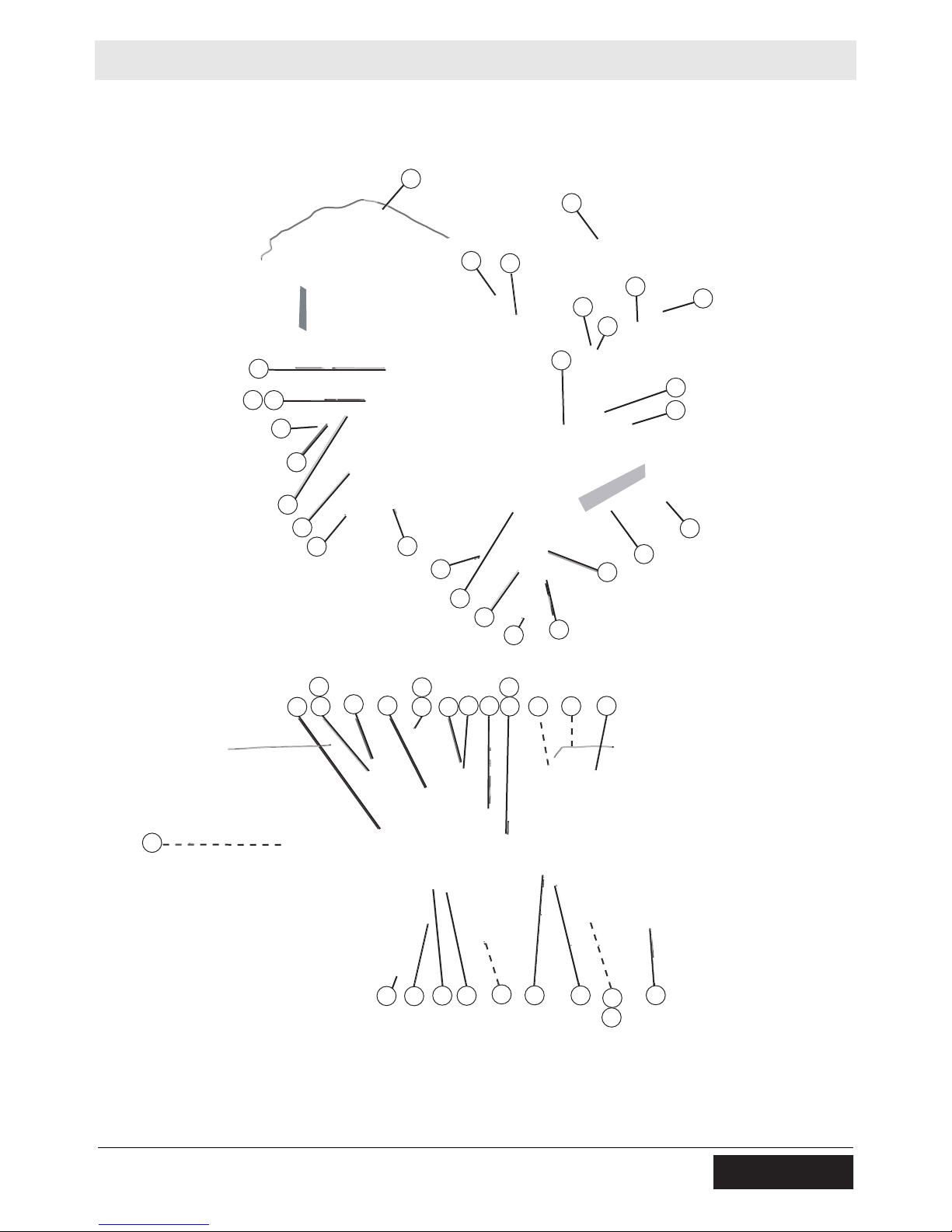
4.1 Features and Controls
See Graphic: wc_gr002946
Ref. Description Ref. Description
1 Air cleaner 24 Operator’s platform
2 Articulated joint 25 Engine oil filter
3 Hand holds 26 Rear drum fill/drain plug
4 Control panel 27 Rear drum—static
5 Dipstick 28 Scraper bar (4 places)
6 Drain hose—hydraulic tank 29 Sightglass—hydraulic tank
7 Drive motor 30 Sprinkler tube (2)
8 Drive pump 31 Steering wheel
9 Engine hood 32 Steering cylinder (under floor panel)
10 Vibration control button 33 Tiedown (2 places)
11 Exciter motor 34 Beacon light (optional)
12 Exciter/Steering pump 35 Battery (under floor panel)
13 Hydraulic filter—return line 36 Hydraulic suction line
14 Hydraulic strainer—suction line 37 Grease fitting—exciter (2 places)
15 Forward / Reverse control 38 Lifting eye (4 places)
16 Front drum—vibratory 39 ROPS
17 Fuel tank fill cap 40 Seat with seatbelt
18 Fuel filter 41 Water drain
19 Grease fittings—articulated joint (4
places)
20 Hydraulic tank fill port 43 Tow valve
21 Hydraulic manifold block 44 Choke lever
22 Water tank fill cap 45 Auxiliary battery positive terminal
23 Lockarm
42 Parking brake
24 wc_tx001071gb.fm
Page 25
RD 12A Operation
9
34
3
31
3
10
15
39
14
45
36
28
38
30
22
40
17
7
16
20
29
13
5
28
28
38
7
18
19
25
37
1
11
21
27
2
26
23
41
30
24
28
33
33
wc_tx001071gb.fm 25
37
12
43
6
8
44
4
32
35
42
wc_gr002946
Page 26
Operation RD 12A
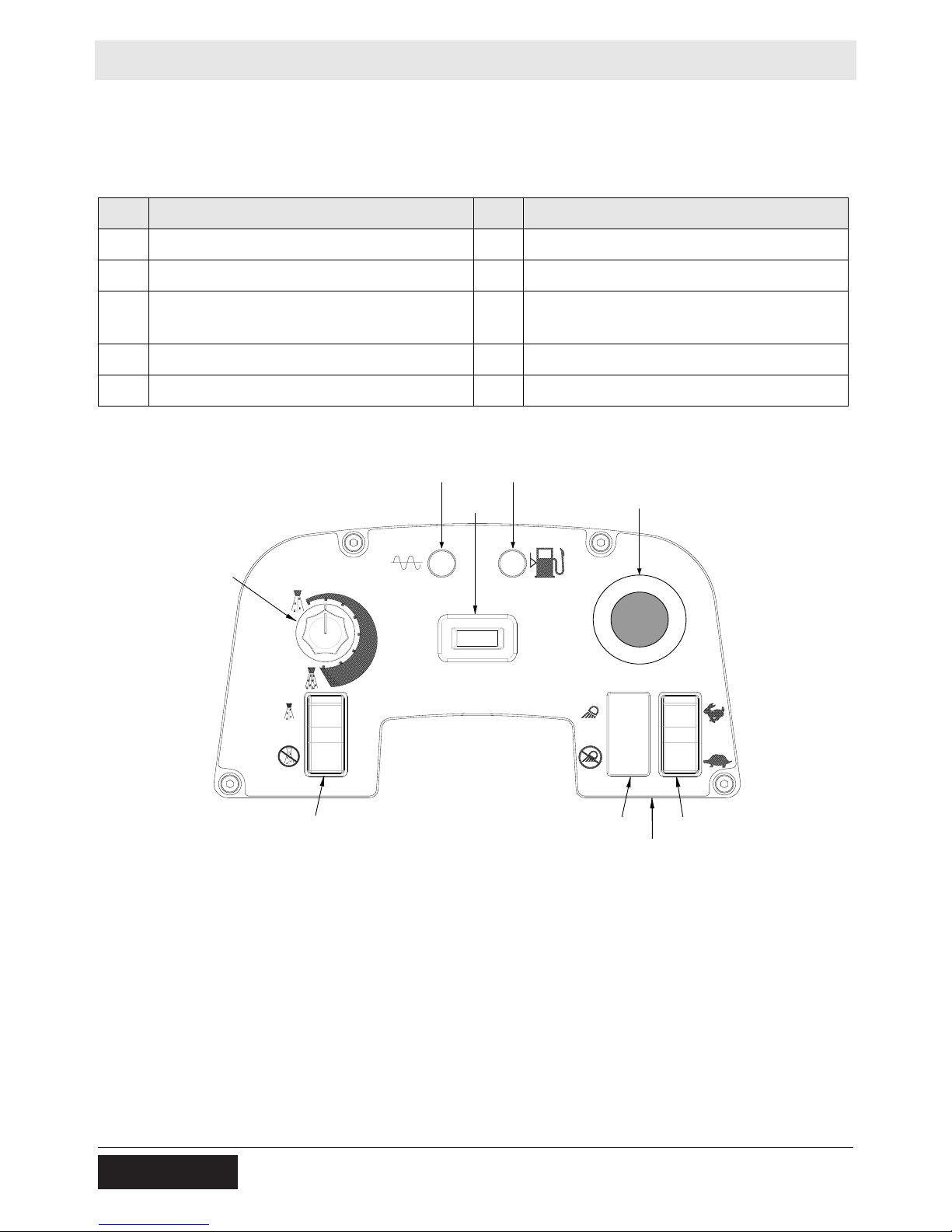
4.2 Control Panel
See Graphic: wc_gr004114
Ref. Description Ref. Description
47 Hour meter 56 Low fuel indicator
50 Vibration ON indicator 61 Water spray switch - ON and OFF
53 Lights switch - ON and OFF
62 Water spray dial
(if equipped)
54 Throttle switch - HIGH and LOW 63 Emergency stop switch
55 Ignition switch — —
50
62
47
56
63
61
55
54
wc_gr004114
53
26 wc_tx001071gb.fm
Page 27

RD 12A Operation
4.3 Preparing the Machine for First Use
Preparing for first use
To prepare your machine for first use:
4.3.1 Make sure all loose packaging materials have been removed from the
machine.
4.3.2 Check the machine and its components for damage. If there is visible
damage, do not operate the machine! Contact your Wacker Neuson
dealer immediately for assistance.
4.3.3 Take inventory of all items included with the machine and verify that
all loose components and fasteners are accounted for.
4.3.4 Attach component parts not already attached.
4.3.5 Add fluids as needed and applicable, including fuel, engine oil, and
battery acid.
4.3.6 Move the machine to its operating location.
4.4 Position of the Operator
Safe and efficient use of this machine is the operator’s responsibility.
Full control of the machine is not possible unless the operator
maintains the proper working position at all times.
While operating this machine, the operator must:
• be seated in the operator’s seat facing forward
• wear the seat belt, properly adjusted and latched
• have both feet on the control deck
• have one hand on the steering wheel at all times
• have the other hand free to operate the controls as needed
4.5 Recommended Fuel
The engine requires regular grade unleaded gasoline. Use only fresh,
clean gasoline. Gasoline containing water or dirt will damage fuel
system. Consult engine owner’s manual for complete fuel
specifications.
wc_tx001071gb.fm 27
Page 28

Operation RD 12A
4.6 Roll Over Protection Structure (ROPS)
The machine is equipped with a Roll Over Protection Structure
(ROPS). The machine is normally delivered to the customer with the
ROPS folded forward to facilitate transport.
Do not use the machine without the ROPS in place. The ROPS is
designed to protect the operator in a rollover accident.
WARNING
Before using the machine, position the ROPS in the fully upright
position as follows:
4.6.1 Support the ROPS using a crane and suitable rigging capable of
supporting 43 kg (95 lbs.).
NOTICE: Do not use the ROPS to lift the machine.
4.6.2 Remove the shipping strap from both sides of the frame. Save the
washers.
4.6.3 Loosen the bottom mounting bolt on both sides.
4.6.4 Rotate the ROPS into the upright position.
4.6.5 Secure the ROPS to the frame using the saved washers and the
supplied bolts. Torque hardware to 106 Nm (78 ft.lbs.).
Each month, check the torque on all of the screws holding the ROPS
in place. Check that the ROPS frame is not rusty, cracked, broken, or
damaged in any way.
Change the seat belts every 3 years, or any time they have been
subjected to accident-level loads.
If the ROPS has been removed from the machine, it must be
reinstalled before the machine is used. When reinstalling the ROPS,
use the original nuts and bolts and tighten the bolts to the specified
torques.
Do not weld or drill into the ROPS. Drilling or welding on the ROPS will
nullify the ROPS certification.
28 wc_tx001071gb.fm
Page 29

RD 12A Operation
4.7 Foldable Roll Over Protection Structure (ROPS) (if equipped)
See Graphic: wc_gr002957
The machine is equipped with a Roll Over Protection Structure
(ROPS). The machine is normally delivered to the customer with the
ROPS folded forward to facilitate transport.
Do not use the machine without the ROPS in place. The ROPS is
designed to protect the operator in a rollover accident.
WARNING
Before using the machine, position the ROPS in the fully upright
position as follows:
4.7.1 Support the upper mass ROPS using a crane and suitable rigging
capable of supporting 19 kg (42 lbs.).
NOTICE: Do not use the ROPS to lift the machine.
4.7.2 Remove the safety pin (a) and pull out the locking pin (b). Do so on
both sides.
4.7.3 Lift the ROPS into the upright position.
4.7.4 Insert the locking pins and secure them with the safety pins.
Be aware of pinch points when lowering and raising the ROPS.
WARNING
To lower the ROPS:
4.7.5 Support the upper mass of the ROPS using a crane and suitable
rigging capable of supporting 19 kg (42 lbs.).
4.7.6 Remove the safety pin (a) and pull out the locking pin (b). Do so on
both sides.
4.7.7 Gently lower the upper mass.
Note: When lowering ROPS, do not allow the upper frame to fall into
the lower position. Allowing the upper mass to slam will weaken the
ROPS system and ultimately compromise its integrity and protection.
4.7.8 Insert the pins in the ROPS in the lower hole setting through the upper
mass to secure it for transport.
Each month, check the torque on all of the screws holding the ROPS
in place. Check that the ROPS frame is not rusty, cracked, broken, or
damaged in any way.
Keep the ROPS in the extended (upright) position when using the
roller, and always use the seat belts provided.
Change the seat belts every 3 years, or any time they have been
subjected to accident-level loads.
wc_tx001071gb.fm 29
Page 30

Operation RD 12A
If the ROPS has been removed from the machine, it must be
reinstalled before the machine is used. When reinstalling the ROPS,
use the original nuts and bolts and tighten the bolts to the specified
torques.
Do not weld or drill into the ROPS. Drilling or welding on the ROPS will
nullify the ROPS certification.
34
b
a
4.8 Rotating Beacon (if equipped)
See Graphic: wc_gr002957
The rotating beacon (34) powers up when the ignition switch is turned
to the ON position.
4.9 Backup Alarm (if equipped)
The backup alarm is located on the rear of the machine.
Start the engine and move the forward/reverse control to the reverse
position. The backup alarm should sound immediately. The backup
alarm will continue to sound until the forward/reverse control is moved
to the neutral position or to the forward position.
If the backup alarm does not sound, make the necessary repairs
before using the roller.
wc_gr002957
30 wc_tx001071gb.fm
Page 31

RD 12A Operation
4.10 Lighting Equipment (if equipped)
See Graphic: wc_gr005892
When working in the dark or in bad visibility, use all the lights available.
Replace broken bulbs immediately. Only replace bulbs when the
machine is turned off. Remember that your safety and the safety of
WARNING
others depends on your care and attention when operating this
machine.
Lights on (B)
This switch position turns on the front and rear lights.
Lights off (D)
This switch position turns off all the lights.
4.11 Seat Belt
See Graphic: wc_gr002238
Pull seat belt (c) out of the retractor in a continuous motion.
Fasten seat belt catch (b) into buckle (a). Make sure that the seat belt
is placed low across the lap of the operator.
The retractor will adjust the belt length and the retractor will lock in
place.
Push the release button (d) on the buckle in order to release the seat
belt. The seat belt will automatically retract into the retractor.
Replace the seat belt every three years.
a
c
d
b
wc_tx001071gb.fm 31
wc_gr002238
Page 32

Operation RD 12A
4.12 Operator Presence System
See Graphic: wc_gr002962
The machine is equipped with an “operator presence system”. This
system is part of the driver's seat and senses the weight of an operator
in the seat. If the operator is not sitting in the driver's seat, the roller will
NOT drive. If the operator leaves the driver's seat and the forward/
reverse control is not in neutral, the engine will be turned off. When the
operator sits down again, the forward/reverse control must be placed
in the neutral position before the roller can be driven or the vibration
can be started.
Note: A one-half second delay keeps the system from tripping when
the roller passes over a bump.
If the roller is supplied with an adjustable seat, it can be adjusted as
follows:
• Knob (a) for adjusting the seat tension to the driver's weight.
• Lever (b) for adjusting the distance from the seat to the driving
controls.
WARNING
Note: Do not change position of the driver’s seat while the machine is
moving. The “OPERATOR PRESENCE” safety device will prevent all
machine movements if an operator is not seated.
Always wear the seat belt provided when operating the roller.
a
b
wc_gr002962
32 wc_tx001071gb.fm
Page 33

RD 12A Operation
4.13 Scraper Bars
See Graphic: wc_gr003447
Scraper bars, located in front of and behind each drum, are used to
prevent dirt and asphalt from sticking to and accumulating on the drum
surface.
These scrapers are spring loaded. They may be set in the travel
position (a) or the scraping position (b) by flipping the bar up or down.
a
b
b
wc_gr003447
a
wc_tx001071gb.fm 33
Page 34

Operation RD 12A
4.14 Anti-Vandalism Protection and Machine Access
Parts of the machine which may be subject to theft or vandalism when
the vehicle is parked unattended can be padlocked to prevent
unauthorized access or use.
Lockable parts are:
• Engine cover.
• Control panel.
• Fuel cap.
To lock the engine cover, close the cover and attach a padlock to the
fastener.
Note: Padlocks are not supplied with the machine.
To lock the fuel cap, close cap completely and push in the locking tab
on the cap and attach padlock.
34 wc_tx001071gb.fm
Page 35

RD 12A Operation
4.15 Articulation Joint Lockarm
See Graphic: wc_gr002956
A lockarm (23), located below the articulated joint, is provided to
secure the front and rear halves of the roller together. Once secured,
the lockarm prevents the two halves from swinging together.
To avoid being pinched by machine halves, set the lockarm before
lifting the machine for transport or repairs!
WARNING
To set lockarm, release it from its holder and swing it out from its stored
position. Place the forward end of the arm into the hole provided in the
front frame of the machine. Secure it in this position using the large
hairpin cotter provided.
ALWAYS disengage and stow locking bar for the articulated steering
joint before operating machine. The machine cannot be steered when
WARNING
the locking bar is engaged.
23
wc_tx001071gb.fm 35
wc_gr002956
Page 36
Operation RD 12A
2
4.16 Machine Stability
WARNING
Crushing hazards. Certain job site conditions or operating practices may adversely
affect machine stability.
f
Follow the instructions below to reduce the risk of tipping or falling incidents.
Surface conditions
Pay attention to changing surface conditions while operating the
machine. Adjust speed and travel direction as necessary to maintain
safe operation.
• Machine stability and traction may be severely reduced when
operating on uneven or rough terrain, rocky soils, or wet or
loosely packed surface material.
• The machine may suddenly tip, sink, or fall when moved onto
surfaces that have been newly filled with earth.
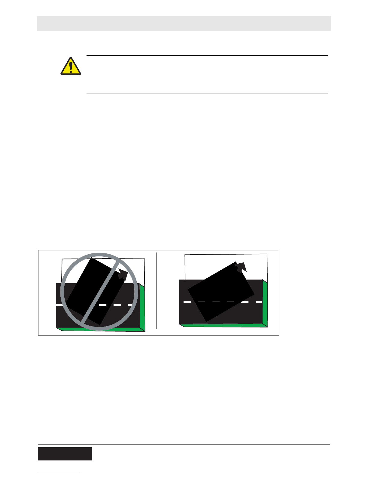
Steering angle
An articulated roller is more likely to tip when moving off an elevated
surface if the machine is turned away from the edge.
• As shown in the illustration on the right, always turn the machine
toward the edge when moving off an elevated surface.
Travel speed
A fast moving machine is more likely to tip or fall over while making
turns or changing direction.
wc_gr00704
• Reduce travel speed before turning the machine.
Drum overhang
The machine can tip suddenly if more than half of the drum width
extends beyond the edge of the elevated surface.
36 wc_tx001071gb.fm
Page 37
RD 12A Operation
• Reduce travel speed and watch the drum position carefully when
operating along the edge of an elevated surface.
• Keep as much of the drum on the elevated surface as possible.
Vibrating on a compacted surface
Activating the vibratory system on a fully compacted surface may
cause the drums to rebound and momentarily lose contact with the
ground. If this occurs while the machine is on an incline, the machine
may slide.
• If the drums rebound on the compacted surface, reduce vibration
speed or stop vibration entirely.
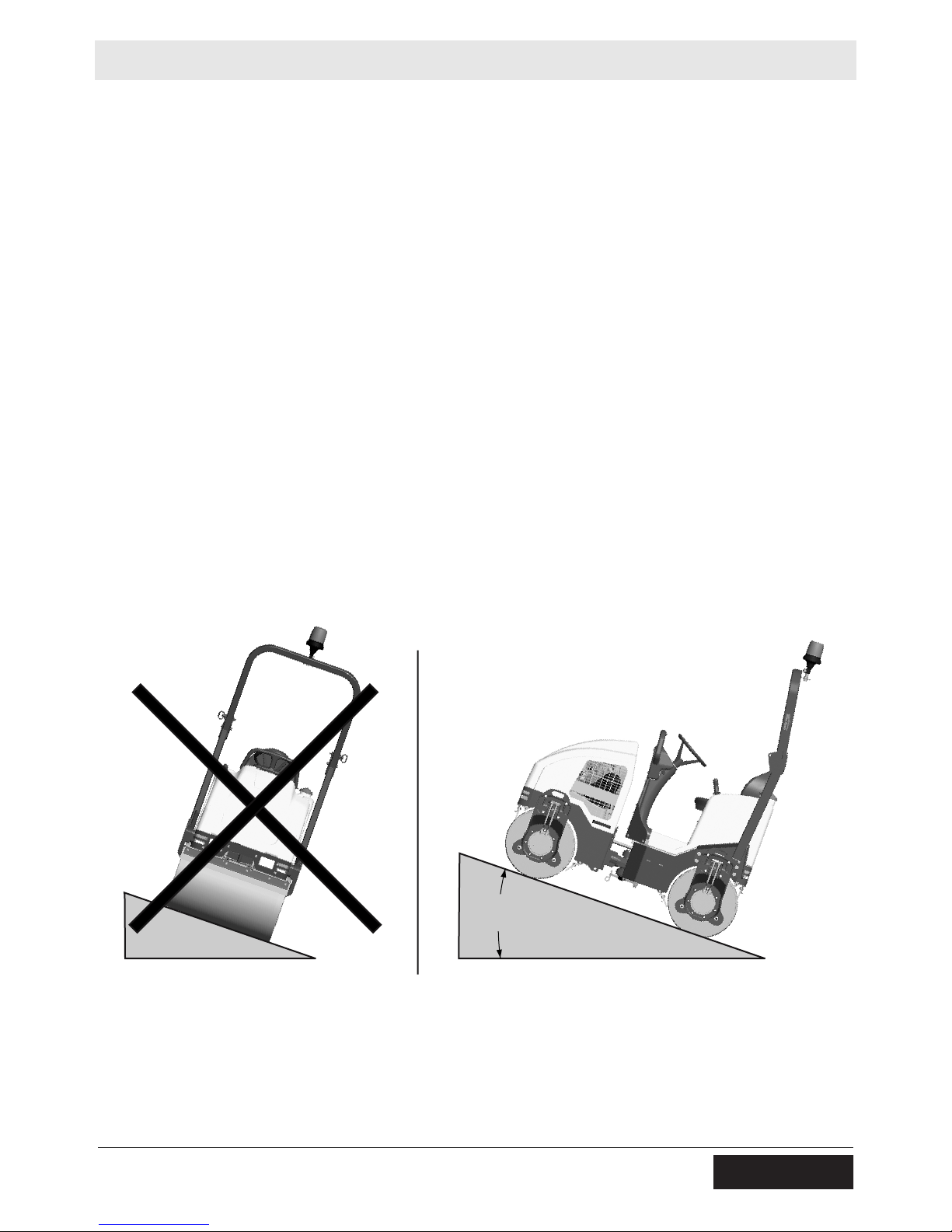
Operation on Slopes
See Graphic: wc_gr003448
When operating on slopes or hills special care must be taken to reduce
the risk of personal injury or damage to the equipment. Always operate
the machine up and down hills rather than from side to side. For safe
operation and for protection of the engine, continuous duty use should
be restricted to front/rear slopes of 17° (30% grade) or less.
WARNING
NEVER operate machine on side slopes. The machine may roll over,
even on stable ground. Always operate the machine parallel to the
slope; never perpendicular.
17˚
30%
wc_gr003448
4.17 Before Starting
Before starting the machine check the following:
• Engine oil level
wc_tx001071gb.fm 37
Page 38

Operation RD 12A
• Hydraulic fluid level
• Condition of fuel lines
• Condition of air cleaner
• Operation of the brake system
• Fuel level
• Water level
• Condition of safety belt
• Scraper bars—clean and properly adjusted
Note: All fluid levels should be checked with the machine on a level
surface.
Ensure that regular maintenance has been carried out.
Ensure that the driver's platform is clean.
Always use the steps and handrails when climbing on and off the
machine.
4.18 Starting
WARNING
See Graphic: wc_gr002951
WARNING
4.18.1 Sit down in the operator’s seat and fasten the seat belt.
4.18.2 Set the forward/reverse control (15) in the neutral position.
4.18.3 If the engine is cold, move the choke lever (44) to the left into the
4.18.4 Check that the parking brake (42) is set. To set the brake, pull the
Always wear the seat belt provided when operating the roller.
Exhaust gases are toxic. Do not start the engine in an enclosed space.
CLOSED position. If the engine is warm, move the choke control to the
right in the OPEN position.
Note: The roller will not start unless the forward/reverse control is in
the NEUTRAL position.
brake lever up until the brake pad engages the drum. To release the
brake lever, lower the lever. Always set the parking brake before
leaving the machine.
4.18.5 Turn the ignition switch (55) to start the engine. If the vibration indicator
light (50) is on, turn the vibration off by pressing the vibration control
button (10).
NOTICE: Do not crank the engine starter for more than 15 seconds at
one time. Longer cranking cycles could lead to starter damage.
38 wc_tx001071gb.fm
Page 39

RD 12A Operation
Note: The ignition switch has an anti-restart feature. If the engine does
not start, the switch will need to be turned to the OFF position before it
will allow the engine to be cranked again.
4.18.6 Gradually place the choke lever in the OPEN position as the engine
warms up. Allow the engine to warm up for a few minutes before
operating the roller.
4.18.7 Before moving the machine, release the parking brake by lowering the
brake lever.
4.18.8 Quickly press and release the upper half of the throttle switch (54) to
bring the engine to high throttle.
Prolonged exposure to high noise levels can damage your hearing.
Wear appropriate hearing protection while operating the roller.
WARNING
wc_tx001071gb.fm 39
Page 40

Operation RD 12A
N
54
44
55
F
10
15
42
R
wc_gr002951
40 wc_tx001071gb.fm
Page 41

RD 12A Operation
4.19 Stopping/Parking
See Graphic: wc_gr002953
4.19.1 Stop the machine on a flat surface with a suitable load bearing
capacity.
4.19.2 Turn the vibration off by pressing the vibration control button (10) on
the forward/reverse lever (15).
4.19.3 Press the water spray switch to the OFF position (61).
4.19.4 Set the forward/reverse control (15) to the NEUTRAL position.
4.19.5 Return the engine throttle to idle by pressing the lower half of the
throttle switch (54) and allow the engine to cool down.
4.19.6 Set the parking brake (42). To set the parking brake, pull the brake
lever up until the brake pad engages the drum. To release the brake,
lower the brake lever. Always set the parking brake before leaving the
machine.
Note: The parking brake engages the rear drum only.
4.19.7 Stop the engine by turning the ignition switch (55) to the OFF position.
If the vehicle constitutes a hazard or obstacle to traffic when parked, it
should be marked with signs, lights, and other warnings.
WARNING
If the machine must be parked on a sloping surface, chock the drums
with wedges to prevent any vehicle movement.
N
54
61
55
F
10
15
42
R
wc_tx001071gb.fm 41
wc_gr002953
Page 42

Operation RD 12A
4.20 Emergency Shutdown Procedure
See Graphic: wc_gr001677
Activate the emergency stop switch (63) by pushing the red button in.
Pushing the emergency stop switch opens the main circuit breaker and
the fuel solenoid, and results in the engine shutting down. The switch
will remain activated until the button is pulled out.
NOTICE: PRESS THE EMERGENCY STOP BUTTON ONLY IN THE
CASE OF AN ACTUAL EMERGENCY WHERE THE MACHINE MUST
BE STOPPED IMMEDIATELY!
If a breakdown/accident occurs while the machine is operating, follow
the procedure below.
4.20.1 Activate the emergency stop switch.
4.20.2 Allow the engine and exhaust system to cool.
4.20.3 Using appropriate equipment, return the machine to an upright
position if tipped over.
4.20.4 Contact rental yard or machine owner.
50
62
61
56
47
53
63
55
54
wc_gr004114
42 wc_tx001071gb.fm
Page 43

RD 12A Operation
4.21 Parking Brake
See Graphic: wc_gr002953
To hold the machine in a stopped position (parked), there is a
mechanical parking brake on the rear drive motor. The engine will
automatically shut off when the operator leaves the seat, but the
parking brake must be set manually.
To set the parking brake (42), pull the brake lever up until the brake
pad engages the rear drum. Always set the parking brake before
leaving the machine. To release the parking brake, lower the brake
lever. The forward/reverse control (15) should be in the NEUTRAL
position when the parking brake is released.
The parking brake is connected to the brake pads and can be adjusted
by turning the knob on the end of the handle. See section Parking
Brake Adjustment.
NOTICE: Under normal operating conditions, do not use the parking
brake when the machine is moving. The parking brake should only be
used in cases of emergency when the machine is moving, e.g.,
following failure of the main hydraulic braking system (moving the
forward/reverse control to the NEUTRAL position) or in a runaway
condition traveling down a slope. Using the parking brake while the
machine is moving may cause damage to the drive motor.
wc_tx001071gb.fm 43
Page 44

Operation RD 12A
4.22 Parking Brake Adjustment
See Graphic: wc_gr002953
The parking brake is located on the rear drive motor drum support, and
is used to prevent the roller from moving when the engine is turned off.
Adjust brake for proper holding force as follows:
4.22.1 Unscrew brake lever knob (42) until brake can be applied with
moderate force (approx. 30 lbs.).
4.22.2 Start roller on level ground and try to travel forward and reverse with
brake applied. If roller drives through brake, stop machine, tighten
lever knob one turn and repeat process.
4.22.3 When machine no longer moves with brake set, stop machine, turn
knob one more turn and brake is properly set.
N
55
F
10
R
54
61
15
42
wc_gr002953
44 wc_tx001071gb.fm
Page 45

RD 12A Operation
4.23 Direction and Speed
See Graphic: wc_gr002953
The forward/reverse control (15) controls both the direction and speed
of the roller. Use the control lever, rather than the throttle, to control the
speed of the machine while compacting.
Speed is controlled by the amount the lever is moved in the direction
of travel—forward or reverse.
During operation, to run the machine at full throttle, press and release
the upper half of the throttle switch (HIGH) (54). This ensures
maximum travel speeds and will produce the best compaction results.
Operating the machine at slower engine speeds will reduce
compaction, slow down machine functions, and damage hydraulic
components.
wc_tx001071gb.fm 45
Page 46

Operation RD 12A
4.24 Transmission
See Graphic: wc_gr002953
Both roller drums are fitted with hydraulic motors which are driven by
an infinitely variable displacement pump and hydrostatic transmission.
Forward and reverse travel are selected using a forward/reverse
control (15) located next to the driver’s seat. In order to comply with
safety standards, the machine has a device which only enables
starting of the engine when the forward/reverse control is in the
NEUTRAL position.
Forward/reverse control
Shift the forward/reverse control (15) into FORWARD (F) or REVERSE
(R) according to the direction of travel desired. The further forward or
reverse the control is positioned, the faster the roller will travel.
Road speed is the same in both FORWARD and REVERSE. If you
wish to change direction of travel from FORWARD to REVERSE or
vice versa, move the control to the NEUTRAL position (N), allow the
vehicle to come to a complete stop, then move the control in the
direction desired.
During operation run the machine at high throttle. Quickly press and
release the upper half of the throttle switch (54) to bring the engine to
high throttle.
When negotiating gentle slopes, keep the engine at high throttle and
the forward/reverse control at the minimum speed position.
NOTICE: This vehicle has a hydrostatic transmission which means
that the forward/reverse control can also be used as an engine brake.
Shifting the control to the NEUTRAL position stops the machine travel.
NOTICE: Never drive the machine at low idle speed. Driving the
machine at low idle speed can damage the drive pump.
46 wc_tx001071gb.fm
Page 47
RD 12A Operation
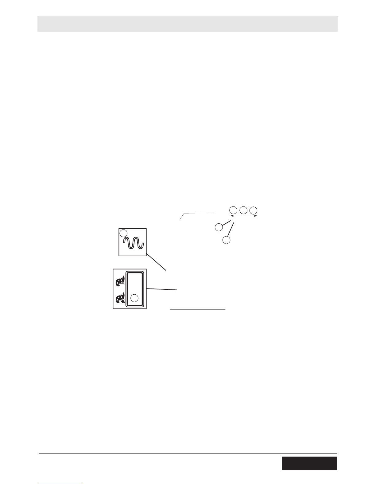
4.25 Vibration
See Graphic: wc_gr005893
The vibration is turned ON or OFF by a push button (10) located on the
forward/reverse control (15). Press the button to turn vibration ON;
press it again to turn it OFF. The vibration ON indicator (50) will light
when vibration is on. The vibration can be turned on while operating in
either forward or reverse and will remain on until it is turned off.
CAUTION: If the machine has been turned off with the vibration on, the
vibration will come on as soon as the machine is restarted. Therefore,
for easier starting and to keep the surface finish smooth, be ready to
switch vibration off should it come on while cranking the engine.
Note: The vibration will remain on even when the forward/reverse
control (15) is in NEUTRAL. When operating on asphalt and in order
to keep the surface finish smooth, turn the vibration off before stopping
the roller.
50
63
10
15
wc_gr005893
N
F
R
wc_tx001071gb.fm 47
Page 48

Operation RD 12A
4.26 Water Spray System
See Graphic: wc_gr002946, wc_gr003638
Water from the tank is fed to the spray bars by an electric pump. The
flow of the water is controlled by a switch and a rotary dial.
Press the upper half of the water spray switch (61) to turn the water
pump on. Turn the water spray dial (62) clockwise to increase the
spray frequency. Turn the water spray dial counter-clockwise to
decrease the spray frequency. Press the lower half of the water spray
switch (61) to turn the water pump off.
Only use clean water. Dirty water, even when filtered, will rapidly clog
the tubes of the spraying equipment.
During winter, or when temperatures drop to below 0°C (32°F), drain
the water tank and spraying equipment. Run the water pump to
remove excess water from the system. Drain the water through the
water drain plug (41) located near the bottom of the rear frame,
through the sprayer end plugs, and the water filter. Freezing water may
cause broken hoses, filters and water pumps and may deform the
water tank.
62
61
wc_gr003638
48 wc_tx001071gb.fm
Page 49

RD 12A Operation
4.27 Auxiliary Battery Positive Terminal
This machine is equipped with an auxiliary battery positive terminal
(45) located on top of the hydraulic tank.
CAUTION! Electric shock hazard. Never touch this terminal and a
metal portion of the machine simultaneously.
CAUTION
45
wc_gr004357
wc_tx001071gb.fm 49
Page 50

Operation RD 12A
4.28 Panel Indicator Lights
See Graphic: wc_gr004118
Vibration on indicator (50)
This indicator light illuminates to indicate that the vibration is on.
Low fuel indicator (56)
This indicator light illuminates to indicate that the fuel level is low.
50
56
wc_gr004118
50 wc_tx001071gb.fm
Page 51

RD 12A Operation
4.29 Adding Ballast to Rear Drum
See Graphic: wc_gr002961
The rear drum can be filled with ballast to provide additional weight.
Add ballast through plug opening (26).
Drum Capacity: 114 liters (30.2 gal.)
Added Weight (water ballast): 113 Kg (250 lbs.)
If water is used as ballast in areas where temperatures are below
freezing, add antifreeze or drain drum after use.
26
wcgr002961
wc_tx001071gb.fm 51
Page 52

Maintenance RD 12A
5 Maintenance
5.1 Engine Maintenance Schedule
The table below lists basic engine maintenance. Tasks designated
with check marks may be performed by the operator. Tasks
designated with square bullet points require special training and
equipment.
Refer to the engine manufacturer’s Operation Manual for additional
information.
Honda
Check fuel level.
Check engine oil level.
Check air cleaner.
Clean engine head and cylinder fins.
Change engine oil.
Clean air cleaner.*
Check and clean spark plug.
Replace engine oil filter.
Check and adjust idle speed.**
Check and adjust valve clearances.**
Daily
before
starting
3
3
3
After
first
month
or
20 hrs.
Every 6
months
or 100
hrs.
Every 9
months
or 200
hrs.
Every
year or
300
hrs.
Every 2
years
or 500
hours
Replace spark plug.
Replace fuel filter.**
Check fuel tube. Replace if necessary.
Replace air filter
(paper element only)
Clean combustion chamber **
* Service more frequently in dusty conditions.
**These items should be serviced by an authorized Honda dealer, unless the owner has the proper
tools and is mechanically proficient. See Honda Shop Manual.
Clean after every 1000 hours.
52 wc_tx001557gb.fm
Page 53

RD 12A Maintenance
5.2 Roller Maintenance Schedule
The table below lists basic machine maintenance. Tasks designated
with check marks may be performed by the operator. Tasks
designated with square bullet points require special training and
equipment.
Check external hardware.
Check level of hydraulic fluid.
Grease articulated joint.
Grease rear drum drive bearings.
Grease exciter bearings.
Check scraper bars.
Check battery.
Grease steering cylinder ends.
Change hydraulic system return line filter.
Clean battery terminals.
Change hydraulic oil.
Daily Every
100
hrs.
3
3
3
Every
600
hrs.
3
Every
1200
hrs.
Daily before starting:
• Check operation of parking brake, making sure it engages.
• Check for leaks around hydraulic hoses and connections.
• Check for leaks around fuel lines and connections.
• Clean engine exterior, cooling fins, and blower housing.
• Check electrical wiring and connections.
• Check operation of NEUTRAL safety switch.
• Inspect seat belt.
New Machines:
• Change engine oil per engine schedule.
• Replace hydraulic system return line filter after first month or 100 hours of
operation.
All machines:
• Increase air cleaner/filter inspections and cleaning under dusty conditions.
wc_tx001557gb.fm 53
Page 54

Maintenance RD 12A
5.3 Rear Frame Access
See Graphic: wc_gr004333
The operator’s platform is mounted on hinges and can be lifted open
to provide access to the water pump, the water filter, the battery, the
hydraulic hoses, and the fuel tank. The platform has lifting cylinders
that hold the platform in the open position.
NOTICE: The lifting cylinders do not have enough force to lift and hold
the platform in the open position when the tank is filled with water. If
there is water in the water tank, drain all water before lifting the
platform.
To open:
5.3.1 Drain water from the water tank. See section Water Spray System.
5.3.2 Remove the two bolts (a) locking the operator’s platform to each side
of the rear frame.
5.3.3 Slowly lift up on the steering column (b).
Note: Lifting the operator’s platform too far can damage the lifting
cylinders and other components.
NOTICE: Do not disconnect the lifting cylinders to open the platform
further. Fuel may leak out of the fuel cap.
To close:
5.3.4 Push down on the platform to return to the operating position.
5.3.5 Replace the two bolts (a) locking the operator’s platform to each side
of the rear frame.
54 wc_tx001557gb.fm
Page 55

RD 12A Maintenance
5.4 Battery
See Graphic: wc_gr002565
Before servicing this machine, make sure the ingnition switch is in the
OFF position and that the battery is disconnected. Attach a “DO NOT
START” sign to the machine. This will notify other personnel that the
unit is being serviced and will reduce the chance of someone
inadvertently trying to start the unit.
Explosion hazard. Batteries can emit explosive hydrogen gas. Keep all
sparks and flames away from the battery. Do not short-circuit battery
WARNING
WARNING
posts. Do not touch the machine frame or the negative terminal of the
battery when working on the positive terminal.
Battery fluid is poisonous and corrosive. In the event of ingestion or
contact with skin or eyes seek medical attention immediately.
Dispose of dead batteries in accordance with local environmental
regulations.
To disconnect the battery:
5.4.1 Stop the machine and shut down the engine.
5.4.2 Place all electrical switches in the OFF position.
5.4.3 Disconnect the negative (–) battery cable from the battery.
5.4.4 Disconnect the positive (+) battery cable from the battery.
To connect the battery:
5.4.5 Connect the positive (+) battery cable to the battery.
5.4.6 Connect the negative (–) battery cable to the battery.
wc_tx001557gb.fm 55
Page 56

Maintenance RD 12A
Inspect the battery periodically. Keep the battery terminals clean and
connections tight.
When necessary, tighten the cables and grease the cable clamps with
petroleum jelly.
Maintain the battery at full charge to improve cold weather starting.
NOTICE: Observe the following to prevent serious damage to the
machine’s electrical system:
• Never disconnect the battery with the machine running.
• Never attempt to run the machine without a battery.
• In the event that the machine has a dead battery, either replace
the battery with a fully charged battery or charge the battery using
an appropriate battery charger.
56 wc_tx001557gb.fm
Page 57

RD 12A Maintenance
5.5 Fuel Filter
See Graphic: wc_gr000163
5.5.1 Change the in-line fuel filter (a) once a year or every 300 hours of
operation. Check the fuel lines and fittings daily for cracks or leaks.
Replace as needed.
Gasoline is extremely flammable! Turn the engine off and allow the
engine to cool before replacing the fuel filter.
WARNING
wc_tx001557gb.fm 57
Page 58

Maintenance RD 12A
5.6 Engine Oil and Filter
Drain oil while engine is still warm.
5.6.1 Remove oil fill cap (a), drain plug (b), and washer (c) to drain oil.
a
c
b
Note: In the interests of environmental protection, place a plastic sheet
and a container under the machine to collect any liquid which drains
off. Dispose of this liquid in accordance with environmental protection
legislation.
5.6.2 Reinstall drain plug and tighten.
5.6.3 Fill engine crankcase with recommended oil to the upper limit mark on
the dipstick (d).
5.6.4 Reinstall oil fill cap and dipstick securely.
d
f
e
g
wc_gr007589
5.6.5 To replace the oil filter (e), remove the installed oil filter after oil has
been drained. Apply a thin coat of oil to the rubber gasket (f) of the
replacement oil filter. Screw the filter on until it just contacts the filter
adapter (g), then turn it an additional 22.24 mm (7/8 in.) turn. Refill with
oil as described above.
58 wc_tx001557gb.fm
Page 59

RD 12A Maintenance
5.7 Spark Plug
See Graphic: wc_gr000028
Clean or replace the spark plug as needed to ensure proper operation.
Refer to the engine owner’s manual.
The exhaust manifold becomes very hot during operation and remains
hot for a while after stopping the engine. Do not touch the exhaust
WARNING
5.7.1 Remove the spark plug and inspect it.
5.7.2 Replace the spark plug if the insulator is cracked or chipped.
5.7.3 Clean the spark plug electrodes with a wire brush.
5.7.4 Set the electrode gap (a).
5.7.5 Tighten the spark plug securely.
manifold while it is hot.
Note: Refer to section Technical Data for the recommended spark
plug type and the electrode gap setting.
NOTICE: A loose spark plug can become very hot and may cause
engine damage.
wc_tx001557gb.fm 59
Page 60

Maintenance RD 12A
5.8 Engine Air Cleaner
NEVER use gasoline or other types of low-flash point solvents for
cleaning the air cleaner. A fire or explosion could result.
WARNING
NOTICE: NEVER run the engine without the air cleaner. Severe
engine damage will occur.
The engine is equipped with a dual-element air cleaner. Under normal
operating conditions, the elements should be cleaned every six
months or 100 hours. Under severe, dry and dusty conditions, the
elements should be maintained daily. Replace an element when it is
saturated with dirt that cannot be removed.
5.8.1 Remove the air cleaner cover (a).
a
c
b
d
wc_gr007591
5.8.2 Loosen the wing nut (b) and remove it.
5.8.3 Remove the filter assembly by pulling it straight up. Inspect both
elements for holes or tears. Replace damaged elements.
5.8.4 Wash the foam element (c) in a solution of mild detergent and warm
water. Rinse it thoroughly in clean water. Allow the element to dry
thoroughly.
5.8.5 Tap the paper element (d) lightly to remove excess dirt or blow
compressed air through the filter from the inside out. Replace the
paper element if it appears heavily soiled.
5.8.6 Reinstall the filter elements.
5.8.7 Reinstall the air cleaner cover.
60 wc_tx001557gb.fm
Page 61

RD 12A Maintenance
5.9 Grease Fittings
See Graphic: wc_gr003457
See section Technical Data for oil quantity and type.
Articulation Joint Lockarm:
The articulated joint is equipped with grease fittings (a) for lubrication.
To avoid being pinched by the machine halves, set the lockarm before
greasing the articulating joint!
WARNING
Rear Drum:
The rear drum drive bearing is equipped with a grease fitting (b)
located at the center of the drum behind the right rear drum support.
Exciter:
The exciter is grease lubricated. There are two grease fittings (c), one
on each side of the machine, located behind the front drum supports.
Steering Cylinder:
The steering cylinder is located under the operator’s platform. There is
a grease fitting near the base and rod ends of the cylinder (d).
a
a
b
c
wc_tx001557gb.fm 61
d
wc_gr003457
Page 62

Maintenance RD 12A
5.10 Hydraulic System Cleanliness
Keeping the hydraulic oil clean is a vital factor affecting the service life
of hydraulic components. Oil in hydraulic systems is used not only to
transfer power, but also to lubricate the hydraulic components used in
the system. Keeping the hydraulic system clean will help avoid costly
downtime and repairs.
Major sources of hydraulic system contamination include:
• Particles of dirt introduced when the hydraulic system is opened
for maintenance or repair
• Contaminants generated by the mechanical components of the
system during operation
• Improper storage and handling of hydraulic oil
• Use of the wrong type of hydraulic oil
• Leakage in lines and fittings
To minimize hydraulic oil contamination:
CLEAN hydraulic connections before opening the lines. When adding
oil, clean the hydraulic tank filler cap and surrounding area before
removing it.
AVOID opening the pumps, motors, or hose connections unless
absolutely necessary.
PLUG or cap all open hydraulic connections while servicing the
system.
CLEAN and cover the containers, funnels, and spouts used to store
and transfer the hydraulic oil.
CHANGE the hydraulic filters and oils at the recommended service
intervals.
62 wc_tx001557gb.fm
Page 63

RD 12A Maintenance
5.11 Hydraulic Oil Requirements
Wacker Neuson recommends the use of a good petroleum-based,
anti-wear hydraulic oil in the hydraulic system of this equipment. Good
anti-wear hydraulic oils contain special additives to reduce oxidation,
prevent foaming, and provide for good water separation.
When selecting hydraulic oil for your machine, be sure to specify antiwear properties. Most hydraulic oil suppliers will provide assistance in
finding the correct hydraulic oil for your machine.
Avoid mixing different brands and grades of hydraulic oils.
Most hydraulic oils are available in different viscosities.
The SAE number for an oil is used strictly to identify viscosity—it does
not indicate the type of oil (engine, hydraulic, gear, etc.).
When selecting a hydraulic oil be sure it matches the specified SAE
viscosity rating and is intended to be used as a hydraulic oil. See
section Technical Data—Lubrication.
wc_tx001557gb.fm 63
Page 64

Maintenance RD 12A
5.12 Hydraulic Oil Level
See Graphic: wc_gr005894
A hydraulic oil level sightglass (29) is located on the side of the
hydraulic fluid reservoir.
While the machine is turned off, check that the hydraulic oil level is
visible at the middle level or higher in the sightglass. If it is not, add oil
through the filler port (20) inside the engine compartment. Use only
clean hydraulic oil.
Thoroughly clean the top of the filler cap before removing it from the
tank. Care should be taken to prevent small dirt particles from entering
the system.
If hydraulic oil continually needs to be added, inspect hoses and
connections for possible leaks.
14
5.13 Hydraulic Suction Strainer
See Graphic: wc_gr005894
A hydraulic strainer (14) is located in the hydraulic tank. This strainer
will not normally require service and does not need to be replaced
when changing the hydraulic oil.
20
29
wc_gr005894
64 wc_tx001557gb.fm
Page 65

RD 12A Maintenance
5.14 Changing the Hydraulic Oil & Filter
All oils eventually shear or thin out with use, reducing their lubricating
ability. In addition, heat, oxidation, and contamination may cause the
formation of sludge, gum, or varnish in the system. For these reasons,
it is important to change the hydraulic oil at specified intervals. See
Maintenance Schedule.
5.14.1 Remove the filler cap/filter cartridge from top of the hydraulic tank.
5.14.2 Remove the drain plug on the drain hose and allow the hydraulic fluid
to drain.
Note: In the interests of environmental protection, place plastic
sheeting and a container under the machine to collect the liquid which
drains off. Dispose of this liquid properly.
5.14.3 Unscrew the return line filter and replace the filter cartridge.
5.14.4 Install the drain plug on the drain hose.
5.14.5 Fill the hydraulic tank through the filler port with clean hydraulic fluid.
5.14.6 Bleed the hydraulic system. See section Bleeding the Hydraulic
System.
5.15 Bleeding the Hydraulic System
5.15.1 Fill the hydraulic system with clean hydraulic oil until it is visible at the
middle level or higher in the sightglass. Do not re-use used hydraulic
oil.
5.15.2 Disconnect the spark plug wires to prevent the engine from starting.
5.15.3 Crank engine 5–10 seconds. This will allow the oil to fill the inlet lines.
5.15.4 Reconnect the spark plug wires.
5.15.5 Place forward/reverse control in the NEUTRAL position. Start the
engine and run the machine at idle for 3–4 minutes.
5.15.6 With the engine still running at idle, move the machine slowly back and
forth from forward to reverse for a short time to bleed air trapped in
drive circuit.
5.15.7 Switch the engine to high idle for 15–20 seconds. Return to low idle for
1 minute. Repeat 2–3 times to bleed the remaining air from the
hydraulic lines.
5.15.8 Check the hydraulic oil level and add oil as required.
Note: If the drive pump chatters or operation is noisy, turn the machine
off and check for air leaks in the inlet line of the charge pump.
5.16 Long-Term Storage
If machine is to be stored for more than 30 days:
wc_tx001557gb.fm 65
Page 66

Maintenance RD 12A
• Drain the fuel tank and drain the water tank. If ballast was added
to the rear drum, also drain the rear drum.
• Change the engine oil.
• Remove the spark plugs and pour approximately 3 ml (1 ounce)
of SAE 30W oil into each engine cylinder through the spark plug
opening.
• Re-install the spark plugs. Leave the ignition wires disconnected
to prevent the engine from starting. Crank the engine for one or
two seconds to distribute the oil inside the engine cylinders. Connect the ignition wires.
• Clean the entire roller and engine compartment.
• Remove dirt from the cooling fins on the engine cylinders and on
the blower housing.
• Set the lockarm to secure the roller halves together.
• Remove the battery from the machine and charge it periodically.
• Cover the entire machine and place it in a dry, protected area.
66 wc_tx001557gb.fm
Page 67

RD 12A Maintenance
5.17 Towing Bypass Valve
See Graphic: wc_gr002960
The drive circuit is equipped with a towing valve (43) to allow oil to
bypass the drive motors and let the roller freewheel for towing.
The towing valve should be used in emergency cases where the
machine has become bogged down in loose or muddy soil, or cannot
be driven due to an engine or hydraulic system failure.
With the towing valve open, the drive circuit has no braking action and
the machine will roll freely. Apply the brake or attach the towing device
WARNING
before opening the towing valve. Close the towing valve immediately
after the towing operation is complete to prevent the machine from
rolling unexpectedly.
To open the bypass, shut the engine off and rotate the shaft on the
towing valve counter-clockwise.
When resuming machine operation, make sure the bypass is closed by
rotating the shaft on the towing valve clockwise.
wc_tx001557gb.fm 67
Page 68

Maintenance RD 12A
5.18 Towing
Improper hookup and towing is hazardous and could result in injury or
death to yourself or others.
WARNING
The towing connection must be rigid, or towing must be done by two
machines of the same size or larger than the towed machine. Connect
a machine on each end of the towed machine.
Be sure that all necessary repairs and adjustments have been made
before a machine that has been towed to a service area, is put back
into operation.
These towing instructions are for moving a disabled machine for a
short distance at a low speed. Move the machine at a speed of 3 km/
h (1.9 mph) or less to a convenient location for repair. These
instructions are only for emergencies. Always haul the machine if
long distance moving is required.
Shielding must be provided on both machines. This will protect the
operator if the tow line or the tow bar breaks.
Do not allow an operator to be on the machine that is being towed
unless the operator can control the steering and/or the braking.
Before towing, make sure that the tow line or the tow bar is in good
condition. Make sure that the tow line or the tow bar has enough
strength for the towing procedure that is involved. The strength of the
towing line or the tow bar should be at least 150 percent of the gross
weight of the towing machine. This is true for a disabled machine that
is stuck in the mud and for towing on a grade.
Keep the tow line angle to a minimum. Do not exceed a 30 degree
angle from the straight ahead position.
Quick machine movement could overload the tow line or the tow bar.
This could cause the tow line or the tow bar to break. Gradual, steady
machine movement will be more effective.
Normally, the towing machine should be as large as the disabled
machine. Make sure that the towing machine has enough brake
capacity, enough weight, and enough power. The towing machine
must be able to control both machines for the grade that is involved
and for the distance that is involved.
You must provide sufficient control and sufficient braking when you are
moving a disabled machine downhill. This may require a large towing
machine or additional machines that are connected to the rear. This
will prevent the machine from rolling away out of control.
All situation requirements cannot be listed. Minimal towing machine
capacity is required on smooth, level surfaces. On inclines in poor
condition or on surfaces in poor condition, maximum towing capacity
is required.
68 wc_tx001557gb.fm
Page 69

RD 12A Maintenance
Attach the towing device and machine before you release the brakes.
If the engine is running, the machine can be towed for a short distance
under certain conditions. The power train and steering system must be
operable.
The operator must steer the machine that is towed in the direction of
the tow line.
Ensure that all instructions in this section are followed carefully.
When the engine is stopped, additional steps may be required before
the machine is towed. In order to avoid damaging the power train, the
steering system, and the brakes, which may be inoperable, additional
steps may be required.
5.18.1 Block the drums in order to prevent movement of the machine. Do not
remove the blocking until the tow vehicle has been positioned and the
tow lines are in place.
5.18.2 Manually release the parking brake. This will prevent excessive wear
and damage to the braking system when towing.
5.18.3 Open bypass valve. See section Bypass Valve.
5.18.4 Attach the tow line to the machine at the tow points.
5.18.5 Attach the tow line to the vehicle that is used to tow the disabled
machine.
5.18.6 Remove the blocks from the drums.
5.18.7 Tow the disabled machine at a slow rate of speed to the desired
location.
NOTICE: Do not tow the roller long distances or at speeds greater than
3 km/h (1.9 mph). Damage to the drive motors may occur.
5.18.8 Once the machine is at the desired location, securely block the drums.
This will prevent movement of the machine.
5.18.9 Close the bypass valve.
5.18.10 Manually re-engage the parking brake.
5.18.11 Detach the tow lines.
wc_tx001557gb.fm 69
Page 70

Basic Troubleshooting RD 12A
6 Basic Troubleshooting
Problem / Symptom Reason / Remedy
ENGINE DOES NOT
START
ENGINE STOPS BY
ITSELF
NO VIBRATION • Defective switch or poor connection.
• Fuel tank empty.
• Wrong type of fuel.
• Old fuel. Drain tank, change fuel filter and fill with fresh fuel.
• Fuel system not primed.
• Fuel filter restricted or plugged. Replace filter.
• Battery connections loose or corroded. Battery dead.
• Air cleaner element plugged.
• Starter motor defective.
• Fuel solenoids on engine inoperative.
• Starter relay inoperative.
• Electrical connections loose or broken.
• Fuel tank empty.
• Fuel filter plugged.
• Fuel lines broken or loose.
• No spark.
• Solenoid on vibration valve damaged or disconnected.
• Exciter assembly damaged.
• Exciter motor coupling damaged or broken.
• Exciter motor damaged.
• Exciter pump damaged.
• Exciter bearings damaged.
NO TRAVEL or
TRAVEL ONLY IN
ONE DIRECTION
NO STEERING • Steering cylinder damaged.
• Pin sheared on forward/reverse control.
• Control cable loose or broken.
• Drive motor damaged.
• Drive pump damaged.
• Defective relief valve or valves.
• Steering unit damaged.
• Steering relief valve stuck or damaged.
• Articulation joint lockarm engaged.
70 wc_tx001558gb.fm
Page 71
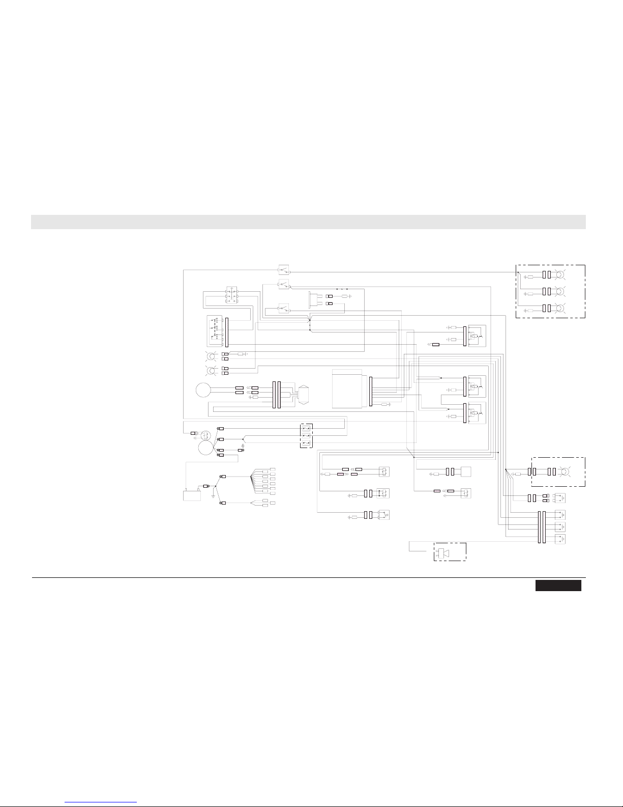
RD 12A Schematics
wc_tx001559gb.fm
7 1
7 Schematics
7.1 Electrical Schematic
LT BLUE/WHITE
LT BLUE/WHITE
TERMINAL
TERMINAL
PUSH ON FEMALE BULLET
PUSH ON FEMALE BULLET
TERMINAL
TERMINAL
PUSH ON MALE BULLET
PUSH ON MALE BULLET
CONNECTOR
CONNECTOR
12 PIN DEUTSCH
12 PIN DEUTSCH
DT06-12SA-P012
DT06-12SA-P012
TERMINAL
TERMINAL
1/4" PUSH ON
1/4" PUSH ON
++-
-
ENGINE
ENGINE
GROUND
GROUND
INTERNAL
INTERNAL
GROUND
GROUND
#24 RED (14 AWG)
#24 RED (14 AWG)
#22 RED/WHITE (14 AWG)
#22 RED/WHITE (14 AWG)
BROWN
BROWN
107
107
OPTIONAL WORK LIGHT HARNESS
OPTIONAL WORK LIGHT HARNESS
#304 BROWN (10 AWG)
#304 BROWN (10 AWG)
BROWN
BROWN
303
303
16 AWG
16 AWG
111
111
BROWN
BROWN
108
108
114
114
301
301
BROWN
BROWN
BROWN
BROWN
BROWN
BROWN
BROWN
BROWN
BROWN
BROWN
109
109
116
116
16 AWG
16 AWG
302
302
16 AWG
16 AWG
BROWN
BROWN
112
112
#24 RED (14 AWG)
#24 RED (14 AWG)
REMOTE START TERMINAL
REMOTE START TERMINAL
#22 RED/WHITE (14 AWG)
#22 RED/WHITE (14 AWG)
#115 BROWN (8 AWG)
#115 BROWN (8 AWG)
#36 RED (10 AWG)
#36 RED (10 AWG)
104
104
106
106
BROWN
BROWN
BROWN
BROWN
BROWN
BROWN
BLUE
BLUE
BROWN
BROWN
102
102
105
105
TERMINAL
TERMINAL
PUSH ON MALE BULLET
PUSH ON MALE BULLET
GREEN #02
GREEN #02
DEUTSCH 2 PIN
DEUTSCH 2 PIN
DT04-2P
DT04-2P
BROWN
BROWN
106
106
WHITE #07
WHITE #07
105
105
BROWN
BROWN
DEUTSCH 2 PIN
DEUTSCH 2 PIN
DT06-2S-P012
DT06-2S-P012
FUSE-20 AMP-MAIN
FUSE-20 AMP-MAIN
#16 RED (14 AWG)
#16 RED (14 AWG)
TERMINAL
TERMINAL
PUSH ON FEMALE BULLET
PUSH ON FEMALE BULLET
107
107
LT BLUE/WHITE #08
LT BLUE/WHITE #08
#21 RED/WHITE (14 AWG)
#21 RED/WHITE (14 AWG)
FUSE-20 AMP-REGULATOR
FUSE-20 AMP-REGULATOR
BLUE
BLUE
BLUE
BLUE
BLACK #12-A
BLACK #12-A
PINK (16 GA) #09-A
PINK (16 GA) #09-A
BLACK (14 AWG) #20
BLACK (14 AWG) #20
#201 RED (14 AWG)
#201 RED (14 AWG)
BLACK/YELLOW
BLACK/YELLOW
WHITE/BLUE
WHITE/BLUE
RED/WHITE (14 AWG) #21
RED/WHITE (14 AWG) #21
#201 RED (14 AWG)
#201 RED (14 AWG)
BLACK/YELLOW #41
BLACK/YELLOW #41
WHITE
WHITE
GRAY #44
GRAY #44
103
103
GRAY
GRAY
BLACK
BLACK
BLACK
BLACK
GRAY #43
GRAY #43
GRAY
GRAY
#03 WHITE
#03 WHITE
#02 GREEN
#02 GREEN
#30 PINK
#30 PINK
114
114
#127 BROWN
#127 BROWN
BROWN
BROWN
#13 RED (14 AWG)
#13 RED (14 AWG)
G
G
BAT
BAT
#202 RED (14 AWG)
#202 RED (14 AWG)
FUSE-20 AMP-LIGHTS
FUSE-20 AMP-LIGHTS
PUMP SWITCH INPUT
PUMP SWITCH INPUT1111
1212GROUND
GROUND
5
5
BRAKE/BYPASS (RD12 FUEL)
BRAKE/BYPASS (RD12 FUEL)
SEAT SWITCH INPUT
SEAT SWITCH INPUT
NEUTRAL SWITCH INPUT
NEUTRAL SWITCH INPUT
SELECT RD12/16 (12V=RD16)
SELECT RD12/16 (12V=RD16)
8
8
7
7
6
6
10
10
9
9
CRANK INPUT
CRANK INPUT
PUMP OUTPUT
PUMP OUTPUT
EMERGENCY STOP INPUT
EMERGENCY STOP INPUT
GLOW PLUG TIMER INPUT
GLOW PLUG TIMER INPUT
4
4
3
3
GLOW PLUG OUTPUT
GLOW PLUG OUTPUT
SWITCHED POWER INPUT
SWITCHED POWER INPUT
2
2
1
1
(16 AWG) PINK #09
(16 AWG) PINK #09
22PINK #26
PINK #26
#09 PINK (16 GA)
#09 PINK (16 GA)
#12-A BLACK
#12-A BLACKSS
LL#09-A PINK (16 AWG)
#09-A PINK (16 AWG)
#12 BLACK
#12 BLACK
3
3
3
3
2
2
PINK #29
PINK #29
#202 RED (14 AWG)
#202 RED (14 AWG)
3
3
2
2
#01 PINK (16 AWG)
#01 PINK (16 AWG)
#18 PINK
#18 PINK
BLACK #12
BLACK #12
PINK #26
PINK #26
PINK #29
PINK #29
PINK #30
PINK #30
DIODE
DIODE
#33 BLACK
#33 BLACK
#04 BLACK
#04 BLACK
#34 PINK
#34 PINK
#06 PINK
#06 PINK
#73 PINK
#73 PINK
#08 LT BLUE/WHITE
#08 LT BLUE/WHITE
-
-
HOURMETER
HOURMETER
+
+
DIODE
DIODE
116
116
BROWN
BROWN
#34 PINK
#34 PINK
#203 GREEN (14 AWG)
#203 GREEN (14 AWG)
#41 BLACK/YELLOW
#41 BLACK/YELLOW
DEUTSCH 2 PIN
DEUTSCH 2 PIN
DT04-2P
DT04-2P
PINK #25
PINK #25
TAN #28
TAN #28
PINK #17
PINK #17
DEUTSCH 2 PIN
DEUTSCH 2 PIN
DT06-2S-P012
DT06-2S-P012
GREEN #19
GREEN #19
TERMINAL
TERMINAL
RING #10
RING #10
TERMINAL
TERMINAL
PUSH ON MALE BULLET
PUSH ON MALE BULLET
DEUTSCH 2 PIN
DEUTSCH 2 PIN
DT06-2S-P012
DT06-2S-P012
BROWN
BROWN
PINK (16 AWG) #11
PINK (16 AWG) #11
DEUTSCH 2 PIN
DEUTSCH 2 PIN
DT06-2S-P012
DT06-2S-P012
DEUTSCH 2 PIN
DEUTSCH 2 PIN
DT04-2P
DT04-2P
BLACK/YELLOW #40
BLACK/YELLOW #40
TERMINAL
TERMINAL
PUSH ON FEMALE BULLET
PUSH ON FEMALE BULLET
#42 PINK
#42 PINK
#40 BLACK/YELLOW
#40 BLACK/YELLOW
102
102
#15 BLACK/YELLOW
#15 BLACK/YELLOW
PINK #25
PINK #25
PINK #27
PINK #27
PINK #14
PINK #14
PINK #05
PINK #05
INTERNAL
INTERNAL
BK/YL
BK/YL
#07 WHITE
#07 WHITE
DEUTSCH 2 PIN
DEUTSCH 2 PIN
DT04-2P
DT04-2P
RED
RED
BLACK
BLACK
#23 WHITE
#23 WHITE
104
104
#06 PINK
#06 PINK
#03 WHITE
#03 WHITE
PINK #14
PINK #14
#6 BLACK
#6 BLACK
PINK #27
PINK #27
GREEN #19
GREEN #19
#2 BLACK
#2 BLACK
#4 RED
#4 RED
DEUTSCH 2 PIN
DEUTSCH 2 PIN
DT04-2P
DT04-2P
DEUTSCH 2 PIN
DEUTSCH 2 PIN
DT06-2S
DT06-2S
TERMINALS
TERMINALS
PUSH ON 1/4"
PUSH ON 1/4"
PINK #05
PINK #05
DEUTSCH 6 PIN
DEUTSCH 6 PIN
DT06-6S-P012
DT06-6S-P012
BLACK #31
BLACK #31
WHITE #23
WHITE #23
#5 BLACK
#5 BLACK
DEUTSCH 6 PIN
DEUTSCH 6 PIN
DT04-6P
DT04-6P
#1 WHITE
#1 WHITE
#3 GREEN
#3 GREEN
DEUTSCH 2 PIN
DEUTSCH 2 PIN
DT06-2S-P012
DT06-2S-P012
PINK
PINK
TAN
TAN
DEUTSCH 2 PIN
DEUTSCH 2 PIN
DT04-2P-E004
DT04-2P-E004
BROWN
BROWN
PINK #201
PINK #201
BROWN #202
BROWN #202
OPTIONAL
OPTIONAL
163676
163676
BLACK (14 AWG) #20
BLACK (14 AWG) #20
IGNITION COIL GRND
IGNITION COIL GRND
(MAGNETO KILL)
(MAGNETO KILL)
(BLACK/PINK)
(BLACK/PINK)
#28 TAN
#28 TAN
#32 BLACK
#32 BLACK
#33 BLACK
#33 BLACK
#11 PINK (16 AWG)
#11 PINK (16 AWG)
BROWN
BROWN
#18 PINK
#18 PINK
#15 BLACK/YELLOW
#15 BLACK/YELLOW
109
109
BLACK #32
BLACK #32
BLACK #31
BLACK #31
#01 PINK (16 GA)
#01 PINK (16 GA)
RED (14 AWG) #16
RED (14 AWG) #16
RED (14 AWG) #13
RED (14 AWG) #13
TERMINAL
TERMINAL
PUSH ON MALE BULLET
PUSH ON MALE BULLET
BLACK #04
BLACK #04
86
86
112
112
BLACK #37
BLACK #378686
85
85
87
87
111
111
RED (14 AWG) #35
RED (14 AWG) #35
RED (14 AWG) #35
RED (14 AWG) #353030
85
85
87
87
RED (10 AWG) #38
RED (10 AWG) #383030
101
101
BLACK/PINK #39
BLACK/PINK #39
85
85
87
87
108
108
PINK #42
PINK #42
30
30
86
86
#203 RED (14 AWG)
#203 RED (14 AWG)
PACKARD WEATHERPACK 2 PIN
PACKARD WEATHERPACK 2 PIN
1201 5792
1201 5792
PACKARD WEATHERPACK
PACKARD WEATHERPACK
1201 0973
1201 0973
PACKARD WEATHERPACK 2 PIN
PACKARD WEATHERPACK 2 PIN
1201 5792
1201 5792
302
302
BROWN
BROWN
#204 GREEN (16 AWG)
#204 GREEN (16 AWG)
#205 GREEN (16 AWG)
#205 GREEN (16 AWG)
PACKARD WEATHERPACK
PACKARD WEATHERPACK
1201 0973
1201 0973
301
301
BROWN
BROWN
PACKARD WEATHERPACK 2 PIN
PACKARD WEATHERPACK 2 PIN
1201 5792
1201 5792
#206 GREEN (16 AWG)
#206 GREEN (16 AWG)
PACKARD WEATHERPACK
PACKARD WEATHERPACK
1201 0973
1201 0973
303
303
BROWN
BROWN
OPTIONAL
OPTIONAL
165478
165478
wc_gr007593
29
13
31
10
9
8
30
14
19
16
17
18
7
4
5
6
32
1
2
15
3
20
21
12
11
22
28
27
26
25
24
23
Page 72

Schematics RD 12A
7 2
7.2 Electrical Schematic Components
Ref. Description Ref. Description
1 Work light switch 16 Rear light (optional)
2 Throttle switch 17 Left head light (optional)
3 Pump switch 18 Right head light (optional)
4 Key switch 19 To magneto kill
5 Vibration indicator light (green) 20 Crank relay
6 Low fuel indicator light (amber) 21 Neutral relay
7 Alternator (30A) 22 Spray bar pump
8 Starter solenoid 23 Fuel cutoff solenoid
9 Starter motor 24 Reverse switch
10 Battery 25 Vibration switch
11 Fuel level sensor 26 Neutral switch
12 Vibration solenoid (front) 27 Seat switch
13 Throttle solenoid 28 Strobe light (optional)
14 Pump timer module 29 Backup alarm (optional)
15 Hourmeter 30 Voltage regulator relay
Page 73
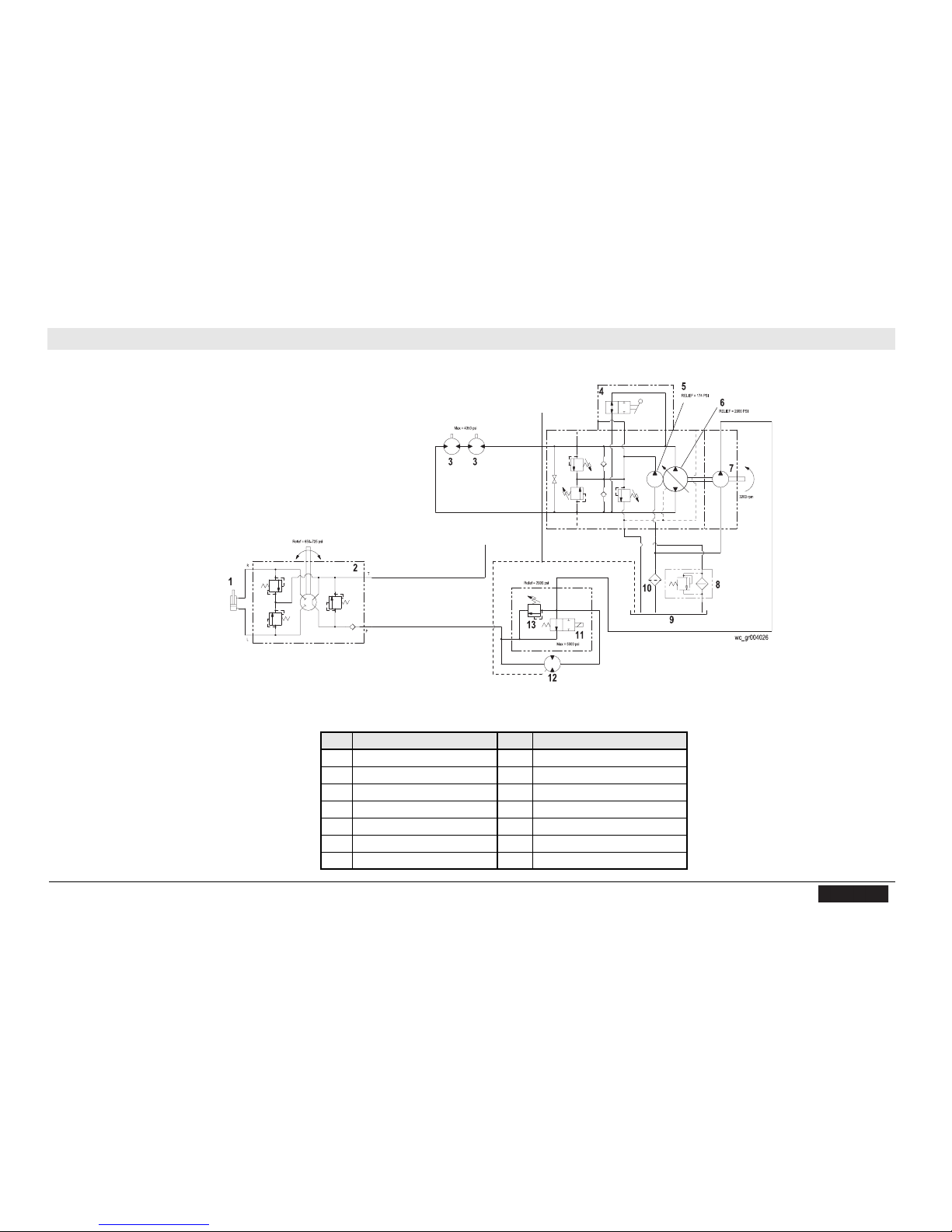
RD 12A Schematics
wc_tx001559gb.fm
7 3
7.3 Hydraulic Schematic
7.4 Hydraulic Schematic Components
Ref. Description Ref. Description
1 Steering cylinder 8 Return filter
2 Steering unit 9 Tank
3 Drive motor 10 Suction strainer
4 Bypass lever 11 Vibration solenoid valve
5 Charge pump 12 Exciter motor
6 Main pump 13 Pressure relief valve
7 Exciter pump - ---
Page 74

Schematics RD 12A
7 4
Notes
Page 75

RD 12A Technical Data
8 Technical Data
8.1 Engine
Engine Power Rating
Net power rating per SAE J1349. Actual power output may vary due to
conditions of specific use.
Item no.
RD 12A
Engine
Engine type 4-stroke, 2 cylinder, air cooled
Engine make Honda
Engine model GX 630
Max. rated power @ rated speed
Displacement
kW (hp)
cm³ (in³)
15.1 (20.3) @ 3600 rpm
688 (42)
Spark plug (NGK) ZFR5F
Electrode gap
Engine speed - operating
Valve clearance (cold)
intake:
exhaust:
mm
(in.)
rpm
mm
(in.)
0.71-0.79
(0.028-0.031)
3100
0.10-0.16
(0.004-0.006)
0.10-0.16
(0.004-0.006)
Battery
U1
12VDC
30AH
350A
Air cleaner
Fuel
Fuel tank capacity
Fuel consumption
Engine oil
Roller
wc_td000411gb.fm 75
type
type
L (gal)
L (gal)/hr
type
L (qt)
Dual element
Regular unleaded gasoline
23 (6.1)
Up to 6.0 (1.59)
10W30 SG, SF/CC, CD
1.9 (2.0)
Page 76

Technical Data RD 12A
8.2 Roller
Item No.
Roller
Dry Weight kg (lb.) 985 (2171)
Curb Clearance:
Right
Left
mm (in.) 399 (15.7)
208 (8.2)
Water Tank Capacity l (gal.) 100 (26.4)
Outside Turning Radius m (ft.) 2.45 (8.0)
Forward / Reverse
Speed
km/hr.
(mph)
0-8.7 (0-5.4)
Gradeability 30%
Vibration Frequency vpm 4200
8.3 Lubrication
RD 12A
Item No.
Hydraulic System
Exciter
Rear Drum Drive
Bearing
Articulated Joint
type
L (gal.)
type
type
qty.
type
qty.
RD 12A
Lubrication
Premium grade, anti-wear hydraulic fluid 10W30
20.8 (5.5)
Mobilgrease XHP222
Mobilgrease XHP222
2-3 shots with hand-held grease gun
Mobilgrease XHP222
2-3 shots with hand-held grease gun
76 wc_td000411gb.fm
Page 77

RD 12A Technical Data
8.4 Dimensions
mm (in.)
2300
(90.6)
560
(22)
1265
(49.8)
1824
(71.8)
8.5 Sound Measurements
The operating sound level is:
• the sound pressure level at operator’s location (L
85.6 dB(A)
1035
(40.8)
pA
900
(35.4)
):
wc_td000411gb.fm 77
Page 78

Technical Data RD 12A
8.6 Vibration Measurements
The operator of this machine should expect to be exposed to vibration
levels listed below when using the machine in performance of its
normally intended function:
• Maximum hand/arm vibration levels are:
1.4 m/s2 (4.6 ft/s2)
These are the representative values of the weighted root mean
square (rms) acceleration to which the hands and arms are subjected. These weighted rms values are measured according to
ISO 5349-1.
• Whole body vibration levels do not exceed:
0.22 m/s2 (0.7 ft/s2)
These are the representative values of the weighted root mean
square (rms) acceleration to which the whole body is subjected.
These weighted rms values are measured according to ISO
2631-1.
The results are compliant to the limit and action vibration values (hand/
arm and whole body) as specified in European directive 2002/44/EC.
8.7 Hydraulic Pressures
System Operating Pressure Relief Pressure
bar psi bar psi
Drive** 55–69 800–1000 200 2900
Steering*
—while turning 0–41 0–725
Vibration
—single drum 55–76 800–1100
* Values for hard-packed surface shown. Values may differ depending on surface.
** Charge pressure: 11.4 – 12.8 bar (165
–185 psi).
45–51 650–725
200 2900
78 wc_td000411gb.fm
Page 79

NOTICE OF COPYRIGHT PROTECTION
AEM Safety Manuals are protected as a copyrighted work with
ownership duly registered with the Copyright Office, Washington,
D.C.Any reproduction,translation, decompiling or other use of an
AEM Safety Manual,or portion thereof, or the creation of deriv-
ative works based on an AEM Safety Manual,without the prior written approval of AEM, is expressly prohibited. Copyright infringement can result in civil and criminal sanctions,damages and other
penalties being imposed.
Copyright © 1978 AEM (Association of Equipment Manufacturers)
Former Copyright © CIMA (Construction Industry Manufacturer Association)
Revised 6/02,9/04
SAFETY ALER T SYMBOL
This Safety Alert Symbol means
ATTENTION is involved!
The Safety Alert Symbol identifies important safety
messages on machines,safety signs, in manuals, or
elsewhere.When you see this symbol, be aler t to
the possibility of personal injury or death. Follow
the instructions in the safety message.
Why is SAFETY important to YOU?
3 BIG REASONS
:
• Accidents KILL or DISABLE
• Accidents COST
•Accidents CAN BE AVOIDED
KE40246P2 6/9/05 3:16 PM Page i
Page 80

WORD OF EXPLANATION................................................................................ 2
FOREWORD.......................................................................................................... 4
A WORD T O THE USER ...................................................................................... 5
FOLLOW A SAFETY PROGRAM ...................................................................... 6
PREPARE FOR SAFE OPERATION.................................................................... 9
START SAFELY ....................................................................................................15
WORK SAFELY .................................................................................................. 18
PARK & SHUTDOWN SAFELY ...................................................................... 23
LOAD & UNLOAD MACHINE SAFELY ........................................................ 25
TRANSPORTING SAFELY .............................................................................. 26
PERFORM MAINTENANCE SAFELY ............................................................ 28
SPECIAL OPERATING AND MAINTENANCE PRECAUTIONS................ 43
TEST Y OUR KNOWLEDGE ............................................................................ 47
A FINAL WORD TO THE USER ...................................................................... 48
1
KE40246P2 6/9/05 3:16 PM Page 1
WORD OF EXPLANA TION
The following is a partial list of reference material on safe operating practices:
U.S.Department of Labor publishes safety and
health regulations and standards under the
authority of the Occupational Safety and Health Act
for the general construction and mining industries.
Its address is: U.S. Department of Labor,200
Constitution Avenue,NW,Washington,DC 20210.
SAE - Society of Automotive Engineers,Inc ., 400
Commonwealth Drive,Warrendale,PA 15096,
publishes a list,"Operator Precautions," SAE J153
MAY, 1987.
Association of Equipment Manufacturers,
111 East Wisconsin Avenue,Milwaukee, WI USA
53202,publishes the Roller Compactor Safety
Manual and other safety-related material.
2
KE40246P2 6/9/05 3:16 PM Page 2
Page 81

3
This Safety Manual covers many different types of
roller compactors … including steel wheel rollers,
vibratory rollers,rubber-tired rollers,segmented
pad/sheepsfoot soil compactors and landfill
compactors. These may be either self-propelled
ride-on,walk-behind or towed rollers.They may be
used for the compaction of asphalt,soil, landfill or
other materials.Excluded from coverage are
vibratory plates and hand rammers.
Regardless of which machine you operate,it is
YOUR responsibility to study and understand this
Safety Manual,and to see that a copy remains
with your machine. The manual begins with your
“safety homework,” takes you step-by-step
through your working day, and ends with
maintenance operations.
Manufacturers produce machines with many
built-in safety features.Employers provide
accident prevention programs.Yet,the ultimate
responsibility to operate and maintain your
machine with the skill,care and knowledge
essential for safety is YOURS.
Do not operate your machine until you have been
trained in the use of all operating controls and
understand the handling characteristics of the
machine.
REMEMBER — SAFETY … YOURS AND THAT OF
THOSE AROUND YOU … IS UP TO YOU!
WORD OF EXPLANA TION
KE40246P2 6/9/05 3:16 PM Page 3
4
This safety manual is intended to point out some of
the basic situations which may be encountered
during the normal operation and maintenance of
your machine,and to suggest possible ways of
dealing with these conditions.
Additional precautions may be necessary,depending
on application,machine type, configuration and
attachments used,and conditions at the work-site
or in the maintenance area.The manufacturer has no
direct control over machine application,operation,
inspection,lubrication or maintenance.Therefore,it
is your responsibility to use good safe practices in
these areas.
The information provided in this manual supplements
the specific information about your machine that is
contained in the manufacturer's manual(s).Other
information which may affect the safe operation of
your machine may be contained on safety signs,or in
insurance requirements,employer's safety programs,
safety codes,local, state/provincial and federal laws,
rules and regulations.
If you do not understand any of this information,or
if errors or contradictions seem to exist,consult with
your supervisor before operating your machine.
IMPORTANT:If you do not have the
manufacturer's manual(s) for your particular
machine, get a replacement manual from your
employer,equipment dealer,or manufacturer
of your machine. Keep this safety manual and
the manufacturer's manual(s) with your
machine.
Unauthorized modifications of machines create
hazards.Machines should not be modified or altered
unless prior approval is obtained from the manufacturer.
FOREWORD
KE40246P2 6/9/05 3:16 PM Page 4
Page 82

It is your responsibility to read and understand this
safety manual and the manufacturer's manual(s)
before operating your machine.This safety manual
takes you step-by-step through your working day.
Remember that YOU are the key to safety.Good
safety practices not only protect you but also
protect the people around you.Study this manual
and the manufacturer's manual(s) for your specific
machine. Make them a working part of your safety
program.Keep in mind that this safety manual is
written for only this type of machine.Practice all
other usual and customary safe working precautions,
and above all — (FIG.1)
REMEMBER — SAFETY IS UP TO YOU
YOU CAN PREVENT
SERIOUS INJURY OR DEATH
5
A WORD TO THE USER
KE40246P2 6/9/05 3:16 PM Page 5
6
KNOW THE RULES
Every employer is concerned about safety. Safe
operation and proper maintenance of your machine
can prevent accidents.KNOW the rules — LIVE by
them.(FIG. 2)
When starting work at a new site,check with the
designated safety coordinator for specific safety
instructions.DON’T LEARN SAFETY THE HARD
WAY .
Know the meaning of all hand signals,signal flags,
signs and markings.
Know the traffic rules used at the work site.Know
who the signal person is;watch and obey their signals.
Know where the fire extinguishers and first aid kits
are kept and how to use them.Know where to get
proper aid and assistance when needed.
Use common sense to avoid accidents.If an
accident does occur,be prepared to react to it
quickly and effectively. NEVER PANIC.
Know how to use the emergency communications
system to summon help when necessary.
FOLLOW A SAFETY PROGRAM
KE40246P2 6/9/05 3:16 PM Page 6
Page 83

7
KNOW WHAT IT IS?
Consult your supervisor for specific instructions on
a job,and the personal safety equipment required.
For instance,you may need:
• Hard Hat
• Safety Shoes
• Eye Protection
• Face Protection
• Heavy Gloves
• Reflector V ests
• Hearing Protection
• Respirators
Do not wear loose clothing or any accessory —
flopping cuffs,untied shoelaces, dangling neckties
and scarves, rings, wrist watches, or other jewelry
— that can catch on protruding or moving parts or
controls.Long hair should be securely bound to
prevent entanglement with moving parts.(FIG.3)
FOLLOW A SAFETY PROGRAM
KE40246P2 6/9/05 3:16 PM Page 7
8
BE ALERT!
Know where to get assistance.Know how to use a
first aid kit and fire extinguisher or fire suppression
system.(FIG. 4)
BE A W ARE!
Take advantage of training programs offered.
Safety programs require that one person at each
jobsite be assigned the overall responsibility and
authority for safety. Know who that person is,
and COMMUNICATE.
Know what the jobsite rules are,and FOLLOW THE
RULES.Be safety conscious,responsible and reliable.
Think about safety BEFORE something happens.
Report unsafe conditions to a supervisor immediately!
BE CAREFUL!
Human error is caused by many factors:
carelessness,fatigue, overload, preoccupation,
incompatibility between operator and the machine,
drugs,and alcohol to name a few.Eliminate these
factors BEFORE accidents occur.Damage to the
machine can be fixed in a short period of time, but
injury,or death has a lasting effect.
FOR YOUR SAFETY AND SAFETY OF
OTHERS,ENCOURAGE YOUR FELLOW
WORKERS T O ACT SAFELY.
FOLLOW A SAFETY PROGRAM
KE40246P2 6/9/05 3:16 PM Page 8
Page 84

LEARN TO BE SAFE
READ the operator’s manual.If one has not been
provided,GET ONE AND STUDY IT BEFORE
OPERATING THE MACHINE.If you have any
questions contact the manufacturer.
Know the positions and understand the functions
of all controls before attempting to operate a
machine. Know the meaning of all identification
symbols on your controls and gauges.(FIG.5)
Know the location of the emergency shut-down
control if the machine is so equipped.
Know the capabilities and limitations of the
machine … such as speed,breaking and steering.
Know the operational and transport dimensions
of your machine to avoid inadvertently hitting
something during operation or transporting.
Carefully read and follow the instructions on all
safety signs on the machine. Keep safety signs in
good condition.Replace missing or damaged
safety signs.
9
PREPARE FOR SAFE OPERATION
NEVER operate a machine which is new to you
without first being instructed in its proper operation.
CHECK IT OUT!
Always conduct a pre-shift inspection before operating
any machine.Know what safety devices your machine
is equipped with … and see that each item is securely
in place and in operating condition.(FIG. 6)
For example:
• Safety Blocks and Locks
• Other Locking Devices
• Lights
• Alarms
• Horn
• Guards and Shields
• Shut-Down Devices
• First Aid Kit
• Fire Extinguishers
KE40246P2 6/9/05 3:17 PM Page 9
TIRES
Inspect pneumatic tires (if so equipped) for
damage, wear,and proper inflation.Never operate
with over-inflated or under-inflated tires. (FIG. 7)
Check that all wheel lug nuts are present and tight.
NEVER START OR OPERATE A MACHINE
KNOWN OR SUSPECTED TO BE DEFECTIVE
OR MALFUNCTIONING.
10
PREPARE FOR SAFE OPERATION
KNOW Y OUR MACHINE
Never operate a machine for which you are not
trained or qualified.
Familiarize yourself with pedals,controls and
instruments – their locations and function.
To handle controls without slipping, wipe them
clean of oil and grease.
Remove tools,supplies and other materials from
the working areas and machine walkways – and
keep these areas free of trash.
Make sure the items you do carry are not loose
or in the way.
ARE REPAIRS MADE?
If your daily check uncovers any item that needs
attention – repair, replacement,or adjustment –
report it to your supervisor and tag the machine
on the start switch and/or other appropriate,
prominent location. A minor malfunction could
be a sign of a more serious problem if the
machine is operated.
KE40246P2 6/9/05 3:17 PM Page 10
Page 85

FIRE PREVENTION
Never allow flammable fluids or materials to
contact hot surfaces.
Never refuel:
• When engine is running
• While smoking
• Near open flames or sparks
• In poorly ventilated area
Never overfill fuel tank or fluid reservoirs.
Clean up spills immediately.
Replace fuel cap securely after filling.
Check for fuel,oil and hydraulic fluid leaks.
Replace worn or damaged hoses/tubes. After
repairs are made,clean the machine before you
operate it.
Inspect electrical wiring for worn or damaged
insulation.Install new wiring if wires are damaged.
11
PREPARE FOR SAFE OPERATION
Because ether or other starting fluids are flammable,
do not smoke when using them. Always follow the
instructions on the container and in the operator’s
manual for your machine.(See page 19.)
Batteries produce explosive gases.Keep open flame
or sparks away.See the manufacturer’s instructions
when servicing the batteries, when using jumper
cables or when using a battery charger.(See pages
36 and 37.)
Remove all trash or debris from the machine.Make
sure that oily rags or other flammable material are
not stored on the machine.(FIG. 8)
KE40246P2 6/9/05 3:17 PM Page 11
PREP ARING TO ROAD THE MACHINE
Know what conditions you will likely encounter:
• Insufficient clearances
• Traffic congestion
• Type of surface
• Steep grades
• Restricted visibility
Determine appropriate warnings to be used.(FIG.9)
Know whether you will need to be escorted.
If the machine is to travel on a road or highway,
refer to the manufacturer’s manual(s) for instructions.
Become familiar with local laws and ordinances affecting
driving on highways.Use “slow moving vehicle” emblem.
Make sure flags,lights, and warning signs are in place.
Select the proper gear before negotiating steep
grades.(FIG. 10)
12
PREPARE FOR SAFE OPERATION
KE40246P2 6/9/05 3:17 PM Page 12
Page 86

Before starting,carefully inspect your machine for
any evidence of physical damage such as cracking,
bending or deformation of plates or welds.Check for
cracking or flaking of paint,which may indicate an
excessive strain or dangerous crack in the material
below.Check for loose, broken or missing parts such
as Roll-Over Protective Structure (ROPS) support
brackets,vibration isolators,and nuts and bolts.If
potentially serious problems are found,do not
operate the machine until appropriate repairs are
completed.
Check the level of all fluids … brake,transmission,
power steering,engine coolant,hydraulic system,and
others.Fill low reservoirs only to the proper level.
Check the various systems (hydraulic,cooling,etc.)
for leaks.(FIG. 11) Inspect all plugs, filler caps and
fittings for tell-tale signs of leaks.ALWAYS use a
flashlight or shielded trouble light when checking …
Never an open flame.Repair any leaks,or have them
repaired by authorized service personnel.(See pages
28 through 42 for additional service cautions.)
Check the fuel level and,if low,fill the tank with the
proper grade of clean fuel before extended operation
(following the instructions on page 34).
A stalled or faltering engine can result in a real
hazard when operating on grades,in traffic or in
heavily congested areas.
NEVER smoke when checking fuel level or refueling.
13
PREPARE FOR SAFE OPERATION
KE40246P2 6/9/05 3:17 PM Page 13
BE SURE THE WORK AREA IS SAFE
Before beginning operation,thoroughly check the
area for any unusual conditions that could be
dangerous.(FIG.12) Check for hidden holes,
drop-offs or overhead obstacles that could be
dangerous.Check the clearance under overhead
power and phone lines.LOOK UP AS WELL AS
DOWN.
Be observant of other workmen, bystanders and
other machines in the area.Be especially careful if
trenches,lightpoles,tiles, buildings, etc . are within
the effective range of a vibratory compactor.
IMPROPER OPERATION COULD RESULT IN
DAMAGE OR INJURY.
Remember,the danger of sliding and/or tipping on
steep slopes is always present … regardless of
how heavy or “stable” your machine may appear to
be.When operating under these conditions, the
use of ROPS and seat belts reduces the hazard to
operating personnel.
14
PREPARE FOR SAFE OPERATION
FIG. 12
KE40246P2 6/9/05 3:17 PM Page 14
Page 87

Walk around your machine once more just prior to
mounting it – checking for people and objects that
might be in the way – then MOUNT PROPERLY
USING STEPS AND HANDHOLDS PROVIDED.
Always use seat belts if your machine is equipped
with a ROPS.
Just before starting,check all controls … such as
forward and reverse, steering, transmission and
throttle to be sure they are in the correct start-up
position.(FIG. 13) The parking brake should be
applied during the start-up operation.
Check for proper functioning of all operating and
shut-down controls.
START CORRECTLY
Know the PROPER starting procedure for your
machine. Follow the manufacturer’s operation
manual … to the letter.
Then,start your engine.
15
START SAFELY
KE40246P2 6/9/05 3:17 PM Page 15
IMMEDIA TELY AFTER ST AR TING
THE ENGINE …
• Observe gauges, instruments, and warning lights to
ensure that they are functioning and their readings
are within the normal operating range.(FIG. 14)
• Be sure work area is safe for test operation of the
various controls and attachments.
• Operate all controls: make certain they operate
properly, and “feel” right. Accustom yourself to the
“feel” of your machine.
• Listen for any unusual noises;smell for any unusual
odors;look for any signs of trouble.
• Check all warning and safety devices and
indicators.
• If safety-related defects or malfunctions are
detected,shut down the machine. Correct it, or
notify your supervisor.DO NOT OPERATE
UNTIL CORRECTED.
Check operation of service and parking brakes on
level ground if possible.
Check service brakes (including hydrostatic brakes,
if so equipped) in both forward and reverse
operation (FIG. 15) ACCORDING T O THE
MANUFACTURERS INSTRUCTIONS.
If an unsafe condition cannot be remedied
immediately,notify your supervisor and tag the
machine on the start switch and/or other
appropriate,prominent location.(See page 28 for
Lockout/Tagout procedure.) No machine
should be operated if any part is not in safe
operating condition.Make certain that any unsafe
condition has been satisfactorily remedied.
16
START SAFELY
KE40246P2 6/9/05 3:17 PM Page 16
Page 88

COLD WEA THER OPERA TION
Consult the engine manufacturer’s operation manual
for proper cold weather starting procedure.
When using cold weather starting aids,be sure to
follow the engine manufacturer’s instructions.
(FIG.16)
After starting, operate all systems slowly and gently
until properly warmed up.
BOOSTER CABLE INSTRUCTIONS
1. Connect positive (+) cable to positive post of
discharged battery.
2. Connect other end of same cable to same marked
post of booster battery.
3. Connect negative (-) cable to other post of
booster battery.
4. Make final connection on stalled vehicle away from
battery,either on vehicle frame or engine block.
5. Start vehicle and remove cables in reverse order
of connection.
17
START SAFELY
KE40246P2 6/9/05 3:17 PM Page 17
REMEMBER THESE RULES
When roading or operating a machine,always stay
in the operator’s station.NEVER mount or dismount
a machine that is moving.Maintain control of your
machine at all times.
ALWAYS operate your machine slowly until fully
familiarized with it’s operation.
Constantly check your total work area for
potential hazards.
Never JUMP on or off your machine.Use the steps
and handholds provided to mount or dismount
safely.Maintain three point contact when mounting
or dismounting.(FIG.17)
• Never use controls or levers as hand holds.
• Never jump off the machine.
Look,listen and smell for possible malfunctions. If
malfunctioning controls or erratic operation are
detected,correct or report them immediately.
DO NOT OPERATE THE MACHINE UNTIL
CORRECTED.
Prevent asphyxiation.If you must operate in a
building or other enclosed area,or if your
machine is equipped with an enclosed cab,be certain there is adequate ventilation.
Use extra care when refueling.(See page 34 for
special precautions.)
18
WORK SAFELY
KE40246P2 6/9/05 3:17 PM Page 18
Page 89

For maximum safety on machines with more than
one operator’s position,operate from the position
giving the greatest visibility of potential hazards.
NEVER allow unqualified or unauthorized personnel
to operate your machine.
NEVER allow other personnel to ride on your
machine unless appropriate seating is provided …
and then only if authorized to do so.
NEVER abuse your machine.Misuse or abuse can
cause an accident.
NEVER enter or place any part of your body in the
“hinge area” or other “pinch” areas of an articulated
machine while the engine is running,or when there is
any chance another person might start the machine.
(FIG.18)
Give the right-of-way to loaded equipment on haul
roads.Maintain a safe distance from personnel,motor
vehicles and other machines.
Your safety,and the safety of those around you, is
determined by the care and judgment YOU use while
operating your machine.
19
WORK SAFELY
KE40246P2 6/9/05 3:17 PM Page 19
20
WORKING ON SLOPES
When working on slopes,avoid sidehill travel
whenever possible … rather operate up and down
the slope. (FIG. 19 & 20) Remember the danger of
sliding and/or tipping on steep slopes is always
present … regardless of how heavy or “stable” your
machine may appear to be.
ALWAYS use seat belts IF your machine is equipped
with a ROPS.
NEVER allow the engine or machine to overspeed.
When climbing or descending steep grades,ALWAYS
select the proper gear BEFORE starting on the slope,
to assure adequate power or engine breaking.
If your machine has a gear shift,select a low gear.
If your machine has a hydrostatic drive,the speed
control should be in the slow travel position,close
to neutral … NEVER in the fully displaced position.
On machines that have a gear shift AND a hydrostatic
control,BOTH controls must be in their slow travel
position.
ALWAYS be sure that manually operated gear type
transmissions are fully engaged BEFORE starting onto
a grade.DO NOT attempt to change the gear selection
while traveling on a grade.See the manufacturer’s
manual for specific instructions.
WORK SAFELY
KE40246P2 6/9/05 3:17 PM Page 20
Page 90

21
Avoid operating your machine too close to an
overhang,deep ditch or hole. If your machine
inadvertently gets close to a tipping condition
or drop-off,STOP and get off the machine
after applying the parking brake … plan your
moves carefully before proceeding.Reversal is
often the best move.
Be alert to potential caving edges,falling rocks
and slides.
Check for overhead obstacles that could be
dangerous.LOOK UP AS WELL AS DOWN.
(FIG.21)
Be alert to obstacles and excessively rough
terrain.Back away from them and go around.
Always travel slowly over rough terrain and
hillsides.Maintain a speed consistent with the
working conditions.
WORK SAFELY
KE40246P2 6/9/05 3:17 PM Page 21
22
When traveling on a public road,obey all traffic
regulations and be sure that the proper clearance
flags,lights and warning signs … such as the “slow
moving vehicle” emblem … are used.(FIG. 22)
NEVER speed … and NEVER coast in neutral.
When roading the machine know your approxi-
mate stopping distance at any given speed.
NEVER turn corners at excessively high speeds.
(FIG.23)
Always look in all directions before reversing
your direction of travel.
Use EXTRA caution when working in close
quarters or when traveling through congested
areas.Courtesy pays off.
WORK SAFELY
KE40246P2 6/9/05 3:17 PM Page 22
Page 91

23
PARK SAFELY
Park in an off the road area,out of traffic,or as
instructed.If necessary to park in a traffic lane , use
the appropriate flags,barriers,flares,lights and
warning signals.Provide advance warning signals in
the traffic lane to warn approaching traffic.
Park on level ground whenever possible.(FIG. 25)
When not possible, position the machine at right
angles to the slope. Make sure the machine is on a
firm footing,and that there is no danger of sliding.
Do NOT leave your machine until you are sure it is
safely blocked in both directions and parking
brakes firmly applied.(FIG. 24)
Lower the blade and all other hydraulically
operated attachments (if so equipped ) to the
ground.
PARK AND SHUT DOWN SAFELY
KE40246P2 6/9/05 3:17 PM Page 23
24
SHUT DOWN PROPERLY
Know the proper shut-down procedure for your
machine.As with the starting procedure, this varies
with the type and model of machine.
Follow the manufacturer’s operation manual for
YOURmachine. Remove the key(s) to prevent
unauthorized starting and movement,and position
and lock any antivandalism devices.
DISMOUNT PROPERLY
NEVER dismount from your machine until it is fully
stopped and the engine is shut off.
NEVER jump off your machine.(FIG. 26) After
stopping,use the steps and handholds provided to
dismount safely.Maintain three point contact when
dismounting.
PARK AND SHUT DOWN SAFELY
KE40246P2 6/9/05 3:17 PM Page 24
Page 92

25
Loading and unloading machines always involves
potential hazards.EXTREME CAUTION SHOULD
BE USED.
Know the correct loading and unloading procedures
for your machine.
All machines are not loaded and unloaded the
same way.The procedures recommended by the
manufacturer should always be followed.
Several precautions are applicable to all machines:
• NEVER load or unload machine by yourself.
• Keep all non-essential personnel clear of loading
and unloading area.
• Load and unload on a level surface.
• ALWAYS use ramps of adequate size and strength.
Be sure ramps are sufficiently wide,and long
enough to provide a safe loading slope.
• NEVER use ramps that are cracked,damaged,or
of questionable strength.(FIG.27)
• Be sure that the ramps are securely positioned
and fastened,and that the two sides are at the
same level as one another.
• The ramp surface must provide adequate traction.
Be sure the surface is clean and free of grease,
oil,ice, and loose material.
• The hauling vehicle should be blocked to prevent
movement during loading or unloading of the
machine.
• For proper tie-down instructions,see the
manufacturer’s manual.
LOAD AND UNLOAD MACHINE SAFELY
KE40246P2 6/9/05 3:17 PM Page 25
26
GENERAL
When towing a machine on a trailer,or a machine
equipped with “portability or transport wheels”,
ALWAYS use a hauling vehicle of sufficient weight,
horsepower and braking capacity to maintain
proper control.
NEVER attempt to tow a trailer or machine if the
hitching devices are of insufficient or questionable
capacity,improperly matched in size or shape,or
positioned at improper heights.
When towing a machine equipped with portability
or transport wheels,ALWAYS follow the
manufacturer’s towing instructions.
BEFORE TOWING
When connecting a trailer to a hauling vehicle,
block under the trailer’s tongue before attempting
to make the connection.NEVERattempt to lift
heavy tongues or move heavy trailers by hand.
NEVER get any part of your body under the
tongue when hitching or unhitching.
ALWAYS make sure the hitch is properly and
securely locked.
ALWAYS use safety chains between the hauling
vehicle and tailer or towed machine.Be sure the
chains are properly and securely connected … at
BOTH ends. Cross the chains under the tongue
when connecting to the hauling vehicle.
ALWAYS make sure electrical and other
connections between the hauling vehicle and trailer
or towed machine are properly and securely made.
After connecting,check the lights for proper
operation.If the towed trailer or machine is
equipped with brakes operable from the hauling
vehicle,check to make sure they are operating
properly.
ALWAYS be sure the portability or transport
wheels,on machines so equipped, are LOCKED
in the lowered position.
Check ALL tires for proper pressure,excessive
or abnormal wear, and potentially dangerous cuts,
bruises or bulges.Have any problems corrected
before proceeding.
TRANSPORTING SAFELY
KE40246P2 6/9/05 3:17 PM Page 26
Page 93

27
TOWING
ALWAYS use EXTRA care when towing a trailer or
machine… when maneuvering in tight places,when backing
(visibility is reduced,and jackknifing must be avoided),and
when towing on steep grades.
Know and obey all local,state and federal laws and
regulations.
NEVER travel at speeds above those recommended by
the manufacturer.
NEVER allow anyone to ride on a trailer or towed
machine. (FIG. 28)
When necessary to disconnect and park a trailer or
towed machine,ALWAYS select a location that is level
and,if possible, one where children are unlikely to be
present. BEFORE disconnecting a trailer,chock the front
AND rear of the wheels,and block under the tongue.
See pages 23 through 24 for parking,shut-down
procedures and roading machine for transport.
TRANSPORTING SAFELY
KE40246P2 6/9/05 3:18 PM Page 27
28
GENERAL
Maintenance work can be hazardous if not done in
a careful manner. All personnel should realize the
hazards and strictly follow safe practices.
NEVER perform any work on the equipment unless
authorized to do so. (FIG. 29) Before performing any
maintenance or repair work,consult the Instruction
Manual. Follow the manufacturer’s recommended
procedures.
BEFORE any maintenance work is begun,review
LOCKOUT/TAGOUT procedures. LOCKOUT
controls and/or energy source and place a warning
label to alert workers of shutdown.
PRIOR to removal of LOCKOUT/TAGOUT, the
equipment must be fully operational and all personnel
accounted for. Except in cases of emergency,the
removal of the LOCKOUT/TAGOUT should be done
by the initiating person prior to the return to start-up.
BEFORE doing any major work,or work on the
electrical system,disconnect the batteries.
REPLACE all missing or broken guards and panels.
USE proper nonflammable cleaning solvents.Follow
solvent manufacturer’s instructions.
ALWAYS remove all flammable materials in the
vicinity of welding and/or burning operations.
PERFORM MAINTENANCE SAFELY
BURNING OR WELDING in the vicinity of acoustical
material may release hazardous fumes.
KE40246P3 6/9/05 3:19 PM Page 28
Page 94

29
PERFORM MAINTENANCE SAFELY
CLOTHING AND PERSONAL
PROTECTIVE ITEMS
Keep hands and clothing well away from engine
fan and moving parts while engine is running.
ALWAYS wear appropriate safety glasses,goggles
or face shield when working.(FIG.30) Proper eye
protection can keep flying par ticles from grinding,
drilling or hammering operations,or fluids such as
fuel,solvents,lubricants and brake fluids,from
damaging your eyes. Normal glasses do NOT
provide adequate protection.
ALWAYS wear a hard hat and safety shoes.(FIG.30)
ALWAYS wear hearing protectors when exposed to
high noise levels for extended periods.ALWAYS wear
a respirator when painting or exposed to dusty
conditions. ALWAYS keep your pockets free of
loose objects which can fall out and drop into
machinery. (FIG. 31) Heavy gloves should be worn
for many operations.
EXHAUST FUMES
Engine exhaust fumes can cause sickness or death.
If it is necessary to run an engine in an enclosed
area,use an exhaust pipe extension. If you do not
have an exhaust pipe extension,be positive the area
is adequately ventilated. (FIG. 32)
HEAVY PARTS
HEAVY PARTS
Handle tools and heavy parts sensibly – with regard
for yourself and other persons. Lower items – don’t
throw or drop them.
ALWAYS use proper hoisting equipment for lifting
heavy loads.
KE40246P3 6/9/05 3:19 PM Page 29
30
• Keep machine in proper adjustment at all times.
Serious injury could result if adjustments are
neglected.
• Whenever possible,AVOID working on a machine
with the engine running.If the engine must be run
to make checks or adjustments,put the transmission
in neutral,set the parking brake and chock the
drum and wheels securely ...front and rear ...to
prevent movement in either direction.
• Personnel can be caught by moving parts when the
guards are removed for access in making repairs.
A repair or maintenance job is not complete until
guards,plates and other safety devices have been
replaced.
• NEVER put your fingers in open gears or reach
through the spokes of a gear.
• Before working on the fuel system,close the fuel
shut-off valve.NEVER smoke or use open flames
near the machine while working on the fuel system.
• Remove and store all tools before resuming
operation.
• Before working in the pivot or “pinch” area of an
articulated machine, securely attach the steering
frame lock to prevent the machine from turning.
(FIG.33) Enter this area only when necessary.
• Connect any other safety locks provided before
proceeding with the work.
PERFORM MAINTENANCE SAFELY
KE40246P3 6/9/05 3:19 PM Page 30
Page 95

31
Before beginning welding or burning operations,drain
fuel lines and tank and move all flammable material to a
safe distance, and be certain a fire extinguisher is readily
available.When welding fuel tanks, either gasoline OR
diesel,ALWAYS drain the tank, fill with water,and leave
cap off during the welding operation.
All guards,plates and other safety devices must
be properly replaced before the machine is
returned to service or serious injur y to you or other
personnel may result.
AVOID burning or welding near acoustical material
whenever possible,as hazardous fumes may be
released.If unavoidable,make sure the area is adequately
ventilated,and that a fire extinguisher is ready available.
ALWAYS use authorized replacement parts that meet
the machine manufacturer’s specifications.
JACKING AND BLOCKING
ALWAYS lower all movable attachments to the ground
or to their lowest position before servicing a machine.
If a machine must be raised for servicing or repairs,
ALWAYS block the machine securely.Use axle stands or
other rigid supports of ample capacity.NEVER rely solely
on the jacks for support. If necessary to work under a
machine, be absolutely certain it is adequately supported.
(FIG.34)
WARNING: Never use concrete blocks for
supports.They can collapse under even light loads.
When jacking up a machine, use a SUITABLE jack,
placed in the proper position,on a solid foundation.
Before working on a machine,chock the drum and
wheels securely … front and rear … in such a manner
as to prevent movement in EITHER direction.Securely
attach the steering frame lock to prevent the machine
from turning.
PERFORM MAINTENANCE SAFELY
KE40246P3 6/9/05 3:19 PM Page 31
32
FIRE PREVENTION
Whenever possible use a nonflammable solvent to
clean parts. Do not use gasoline or other fluids that
give off harmful vapors.
If flammable fluids,such as diesel fuel, must be used,
extinguish open flames or sparks and do not smoke.
Store dangerous fluids in a suitable place,in approved
containers which are clearly marked.NEVER smoke
in areas where flammable fluids are used or stored.
(FIG.35)
Use proper nonflammable cleaning solvents. Follow
solvent manufacturer’s instructions for use.
Always remove all flammable material in the vicinity
of welding and/or burning operations.
ALWAYS keep the floor in the work area clean and
dry.Oily,greasy floors can easily lead to falls. Wet
spots,especially near electrical equipment, can be
hazardous. (FIG. 35)
Know where fire extinguishers are kept – how they
operate – and for what type of fire they are intended.
Check readiness of any fire detectors and fire
suppression systems.
PERFORM MAINTENANCE SAFELY
KE40246P3 6/9/05 3:19 PM Page 32
Page 96

33
FIRE PREVENTION CHECKLIST (FIG. 36)
• Remove debris such as rags,coal dust, oil, leaves,
pine needles.
• Check and repair fuel and hydraulic leaks.
• Check and repair damaged wiring.
• Prevent hose and electrical wire harness
abrasion.
• Tighten loose clamps and fittings.
• Secure loose wiring.
• Make sure guards and protective covers are
in place.
• Make sure fire extinguisher is available and
operable.
PERFORM MAINTENANCE SAFELY
KE40246P3 6/9/05 3:19 PM Page 33
34
REFUELING (FIG. 37)
Precautions
When refueling,the following precautions must be
followed:
• Add proper type and grade of fuel only when
machine is not running and machine is parked with
no one in the cab.
• Fuel in a well-ventilated area.
• Turn off all electrical switches.
• Turn off cab heaters.
• Open lights, lighted smoking materials, flames, or
spark producing devices shall be kept at a safe
distance while refueling.
• Keep fuel nozzle in contact with tank being filled,
or provide a ground to prevent static sparks from
igniting fuel.
• Do not spill fuel on hot surfaces.
• Any spillage shall be cleaned immediately.
• Do not star t engine until fuel cap is secured to
the fuel tank and people are clear of the machine.
• ALWAYS make sure fuel,oil,hydraulic fluid and water
are added to their proper tanks.
PERFORM MAINTENANCE SAFELY
KE40246P3 6/9/05 3:19 PM Page 34
Page 97

35
SERVICING COOLING SYSTEM
When checking coolant level:
• Stop the engine and let the engine and radiator
cool before checking.(FIG.38)
If an overheated engine requires a shutdown:
• Wait for the radiator to cool.The hot
pressurized coolant can cause burn injuries.Never
add coolant to an overheated system.
• Overheating is a symptom of trouble. Stop
the engine and have the trouble corrected before
serious damage occurs.
• If it is necessary to check an overheated engine
use a heavy cloth,gloves,heavy clothing and safety
glasses or goggles to protect yourself.Stand to
the side, turn your face away, and slightly loosen
the cap.Wait until the sound stops before
removing the cap.
PERFORM MAINTENANCE SAFELY
KE40246P3 6/9/05 3:19 PM Page 35
36
SERVICING BATTERIES
Always wear safety glasses and gloves when
working with batteries.
Before removing a battery, turn off all electrical
equipment,then disconnect the negative (-)
battery cable first. Before installing a battery,
turn off all electrical equipment,then connect
the positive (+) battery cable first.
To prevent sparking at the posts when using
a battery charger,always turn the charger off or
disconnect it from its power source before
connecting or disconnecting charger leads to
battery posts. Caps on all cells should be left
on and the vent caps would be covered with
a wet cloth.
Do not short across the battery terminals.
The spark could ignite the gases.
BOOSTER CABLE INSTRUCTIONS (FIG.39)
1. Connect positive (+) cable to positive post of
discharged battery.
2. Connect other end of same cable to same
marked post of booster battery.
3. Connect negative (-) cable to other post of
booster battery.
4. Make final connection on stalled vehicle away
from battery,either on vehicle frame or
engine block.
5. Star t vehicle and remove cables in reverse
order of connection.
PERFORM MAINTENANCE SAFELY
KE40246P3 6/9/05 3:19 PM Page 36
Page 98

37
BATTERY SERVICING
To prevent a battery explosion: (Fig. 40)
• Maintain the electrolyte at the recommended
level.Check level frequently. Add distilled
water to batteries only before starting up,never
when shutting down. With electrolyte at the
proper level,less space is available for gases to
accumulate in the battery.
• Use a flashlight to check the electrolyte level.
Never use a flame. (Fig. 41)
• Do not short across the battery terminals.
The spark could ignite the gases.
Battery acid will burn skin, eat holes in clothing,
and may cause blindness if splashed into eyes.If
you spill acid on yourself flush skin immediately
with lots of water. Apply baking soda to help neutralize the acid. If acids gets in your eyes,flush
immediately with large amounts of water and
seek proper medical treatment immediately.
When servicing batteries,remember that a
lead-acid storage battery generates (when charging
or discharging) hydrogen and oxygen – a very
explosive mixture. A spark of flame could ignite
these gases.
PERFORM MAINTENANCE SAFELY
KE40246P3 6/9/05 3:19 PM Page 37
38
HYDRAULIC SYSTEMS
NOTE: Hydraulic Systems have “special features”.
Some of the features affecting your safety are listed
below.
Pressure can be maintained in hydraulic and air
circuits long after the engine has been shut down.
This pressure can cause hydraulic fluid or items
such as pipe plugs to “shoot out” at high speed if
pressure is not released correctly.Release system
pressure before attempting to make adjustments
or repairs.
Consult the manufacturer’s instructions for correct
procedure.
Before disconnecting hydraulic fluid lines, be sure
you:
• Shut off engine.
• Always release any air pressure (supercharge)
on the hydraulic reservoir.
• Move pedals and control levers repeatedly
through their operating ranges to relieve all
pressures.
Pressurized hydraulic fluid can penetrate the
skin and cause serious injury. Therefore, be sure
all connections are tight and that lines,pipes,and
hoses are in good condition before starting the
engine.
Fluid escaping from a small hole can be almost
invisible.Use a piece of cardboard or wood,
instead of your hands,to search for suspected
leaks.(FIG. 42)
PERFORM MAINTENANCE SAFELY
KE40246P3 6/9/05 3:19 PM Page 38
Page 99

39
HYDRAULIC SYSTEMS (CONT’D)
If you are struck by escaping hydraulic fluid
under pressure,serious injury can occur if
proper medical treatment is not administered
immediately.
During operation,hydraulic fluid and air in an
unvented hydraulic tank becomes heated
and will tend to expand. This will raise the
pressure inside an unvented hydraulic tank.If
the filler cap is removed rapidly,the pressure in
the tank can force the oil out of the tank very
rapidly.The hydraulic fluid may be very
hot and may cause severe burns.Always
relieve tank pressure before removing the cap
completely.Consult the manufacturer’s
instructions for the correct procedure.
When adding fluid to any system,be sure to
use the fluid recommended by the manufacturer.
Certain fluids, when mixed, may destroy seals
causing loss of control and possible personal
injury.
Keep hydraulic relief valve settings set to
the manufacturer’s recommendations.Excessive
pressures could result in structural or
hydraulic failures.Low pressure could result in
loss of control.Either condition could cause
personal injury or death.
Be sure the engine is stopped and machine is
properly locked out and controls tagged,before
working on a machine.Only run engine when it is
essential,as in the case o f pressure adjustments,
lubrication,or tests. Follow the manufacturer’s
recommendations when making adjustments.
Never resume operation until satisfactory
adjustments have been made.The operator
must follow the mechanic’s instructions when
adjustments are being made or machine is
being serviced.
PERFORM MAINTENANCE SAFELY
KE40246P3 6/9/05 3:19 PM Page 39
40
TIRE INSPECTION
Recommended air pressure must be maintained
in every tire.Daily checks assure that inflation is
correct.If your periodic check discloses a tire that
is continuously losing air, a leak is indicated and
must be repaired.(FIG. 43)
During your pressure checks,also inspect for :
• Objects wedged between or embedded in tires.
• Missing valve caps and wheel lugs.
• Cuts, tears, and breaks that may need repair.
• Abnormal or uneven wear.
• Damaged or poor fitting rim or rim flanges.
• Projecting body hardware, loose fender bolts,
spring clips – anything that could contact a tire.
Do not burn or weld on wheels or rims.
PERFORM MAINTENANCE SAFELY
KE40246P3 6/9/05 3:19 PM Page 40
Page 100

41
PNEUMA TIC TIRES
Changing tires or adding air can be a hazardous
business.Special tools and procedures are
required for changing off-highway tires.
Explosion and separation of a tire and/or rim parts
can cause serious injury or death. (FIG. 44) Always
follow the manufacturer’s recommendations or
see your tire supplier.
PERFORM MAINTENANCE SAFELY
TIRE PRESSURE
Check tire pressure before starting operation.
An air pressure rise during operation is normal
and should NOT be reduced.Overloads or overspeeds may produce increased tire pressures d ue
to heat.Never bleed tires.Reduce your load – or
speed – or stop until tires cool.
ADD AIR
From a distance – with air chuck clipped on the
tire valve – and with extension hose that permits
you to stand behind tread.(FIG. 45) Always use a
tire cage or equivalent for protection.
KE40246P3 6/9/05 3:19 PM Page 41
42
ROPS (Roll-Over Protective Structures)
Periodically inspect ROPS for cracks and loose mounting
hardware.
Replace all missing,deteriorated or worn rubber parts.
If it becomes necessary to remove a ROPS,reinstall it only
on the same machine, in its original position. (FIG. 46)
NEVER alter the ROPS in any way without the written
approval of the manufacturer.
NEVER cut holes in or weld on ROPS without the
manufacturer’s approval.
NEVER attempt to repair a damaged ROPS – it must be
replaced with a new unit,approved for that machine.
Periodically inspect seat belts for wear, tear,deterioration
or excessive dirt.Replace them if necessary.
AIR CONDITIONERS
NEVER attempt to weld on or near air conditioners.
Poisonous gas may be formed when refrigerant gas is
exposed to a flame or excessive heat.
Maintenance and repair of air conditioners … except for
very minor repairs or servicing … must be done only by
an experienced air conditioner or refrigeration technician.
(FIG.47)
PERFORM MAINTENANCE SAFELY
KE40246P3 6/9/05 3:19 PM Page 42
 Loading...