

Page 1
Operator's manual
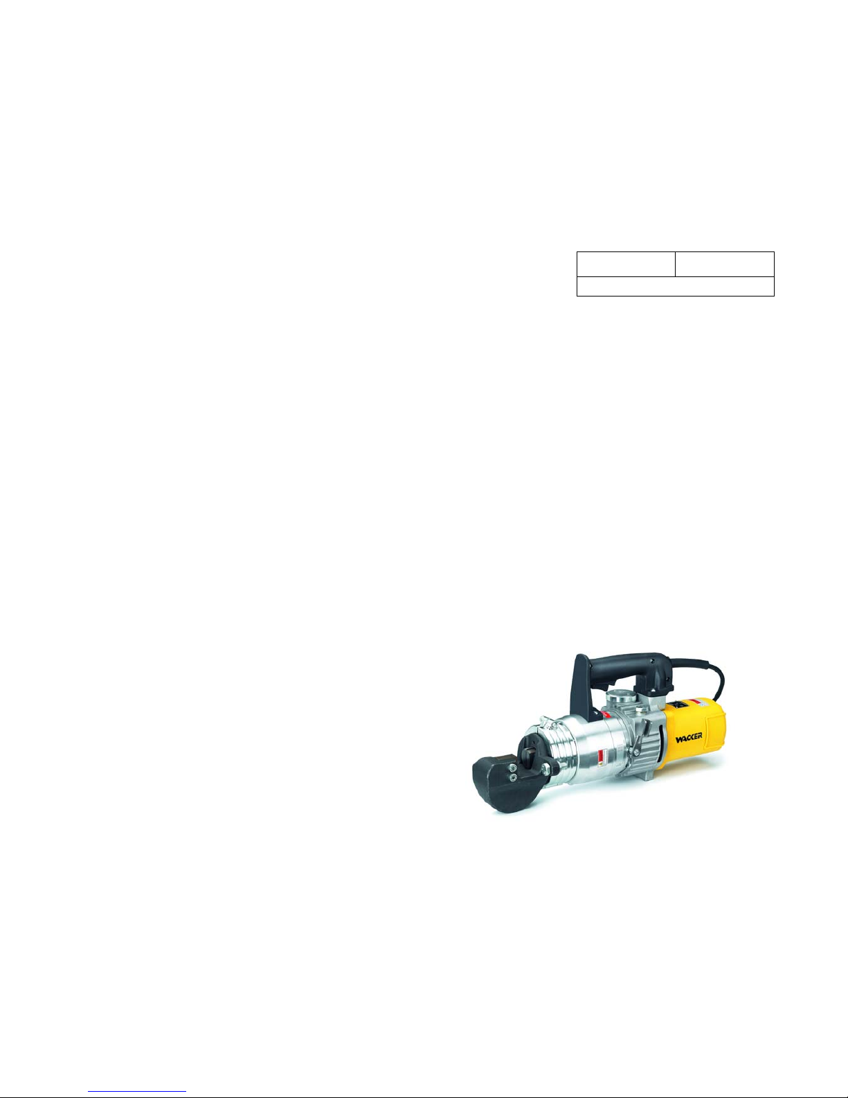
Cutting machine with interchangeable head
RCP
20, 25
0215052en 002
03.2008
Page 2

Page 3

Contents
3
Contents
1 Foreword .................................................................................................................... 5
2 Introduction ...............................................................................................................6
2.1 Means of representation for this operator's manual ........................................... 6
2.2 WACKER representative .................................................................................... 7
2.3 Described machine parts.................................................................................... 7
3 Safety information .................................................................................................... 8
3.1 Principle.............................................................................................................. 8
3.2 Qualification of the operating personnel ........................................................... 11
3.3 Protective gear ................................................................................................. 12
3.4 Transport .......................................................................................................... 12
3.5 Operating safety ............................................................................................... 12
3.6 Safety during the operation of hand machines ................................................. 14
3.7 Safety during the operation of electric appliances............................................ 14
3.8 Safety during the operation of hydraulic machines........................................... 15
3.9 Maintenance..................................................................................................... 15
3.10 Labels............................................................................................................... 16
3.11 Safety devices .................................................................................................. 17
4 Scope of delivery ....................................................................................................18
5 Description ..............................................................................................................19
5.1 Application........................................................................................................ 19
5.2 Functionality ..................................................................................................... 19
5.3 Components and operator's controls................................................................ 19
6 Transport .................................................................................................................22
7 Operation .................................................................................................................23
7.1 Prior to starting the machine............................................................................. 23
7.2 Adjusting the machine ...................................................................................... 24
7.3 Starting up ........................................................................................................ 26
7.4 Decomissioning ................................................................................................ 29
8 Maintenance ............................................................................................................30
8.1 Maintenance schedule...................................................................................... 30
8.2 Maintenance work ............................................................................................ 31
8.2.1 Visual inspection for damage ............................................................... 31
8.2.2 Changing the knife................................................................................ 32
8.2.3 Checking the hydraulic oil level ............................................................ 33
8.2.4 Changing the hydraulic oil .................................................................... 35
8.3 Installing and removing the cutting head .......................................................... 38
Page 4

4
Contents
9 Troubleshooting ...................................................................................................... 41
10 Disposal ...................................................................................................................42
10.1 Disposal of the machine ................................................................................... 42
11 Accessories ............................................................................................................. 43
11.1 General notes................................................................................................... 43
11.2 Bending head ................................................................................................... 43
11.2.1 Safety ................................................................................................... 43
11.2.2 Scope of delivery .................................................................................. 44
11.2.3 Description............................................................................................ 44
11.2.4 Operation.............................................................................................. 46
11.2.5 Technical data for accessories ............................................................. 51
12 Technical data ......................................................................................................... 52
12.1 RCP-20/25 - 230 .............................................................................................. 52
12.2 RCP-20/25 - 115 .............................................................................................. 53
12.3 RCP-20/25 - 120 .............................................................................................. 54
12.4 Extension cable ................................................................................................ 55
EC Declaration of Conformity ................................................................................ 57
DIN EN ISO 9001 Certificate ................................................................................... 59
Page 5

Foreword
5
1Foreword
This operator's manual contains information and procedures for the safe operation and maintenance of your WACKER machine. In the interest of your own
safety and to prevent accidents, you should carefully read through the safety information, familiarize yourself with it and observe it at all times.
This operator's manual is not a manual for extensive maintenance and repair
work. Such work should be carried out by WACKER Service or authorized specialists.
The safety of the operator was one of the most important aspects taken into consideration when this machine was designed. Nevertheless, improper use or incorrect maintenance can pose a risk. Please operate and maintain your
WACKER machine in accordance with the instructions in this operator's manual.
Your reward will be troublefree operation and a high degree of availability.
Defective machine parts must be replaced immediately!
Please contact your WACKER representative if you have any questions concerning operation or maintenance.
All rights reserved, especially reproduction and distribution rights.
Copyright 2008 Wacker Construction Equipment AG
No part of this publication may be reproduced in any form or by any means, electronic or mechanical, including photocopying, without the expressed written permission of WACKER.
Any type of reproduction, distribution or storage on data media of any type and
form not authorized by WACKER represents an infringement of copyright and will
be prosecuted.
We expressly reserve the right to make technical modifications – even without
special notice – which aim at further improving our machines or their safety standards.
Page 6

6
Introduction
2 Introduction
2.1 Means of representation for this operator's manual
Warning symbols
This operator's manual contains safety imformation of the categories:
DANGER, WARNING, CAUTION, NOTICE.
They should be followed to prevent danger to life and limb or damage to equipment or improper service.
Notes
Note: Complementary information will be displayed here.
Instructions
f This symbol indicates there is something for you to do.
1. Numbered instructions indicate that you have to carry out something in a defined
sequence.
This symbol is used for lists.
DANGER
This warning notice indicates hazards that result in serious injury or even death.
f Danger can be avoided by the following the actions mentioned.
WARNING
This warning notice indicates hazards that can result in serious injury or even
death.
f Danger can be avoided by the following the actions mentioned.
CAUTION
This warning notice indicates hazards that can result in minor injury.
f Danger can be avoided by the following the actions mentioned.
NOTICE
This warning notice indicates hazards that can result in material damage.
f Danger can be avoided by the following the actions mentioned.
Page 7

Introduction
7
2.2 WACKER representative
Depending on your country, your WACKER representative is your WACKER
Service, your WACKER affiliate or your WACKER dealer.
You can find the addresses in the Internet at www.wackergroup.com.
The addresses of the WACKER main locations are located at the end of this operator's manual.
2.3 Described machine parts
This operator's manual is valid for different machine parts from a product range.
Therefore some figures can differ from the actual appearance of your machine.
It is also possible that the descriptions include components which are not a part
of your machine.
Details for the described machine types can be found in the chapter Technical
Data.
Page 8

8
Safety information RCP
3 Safety information
3.1 Principle
State of the art
This machine has been constructed with state-of-the-art technology according to
the recognized rules of safety. Nevertheless, when used improperly, dangers to
the life and limb of the operator or to third persons or damage to the machine or
other materials cannot be excluded.
Proper use
The machine may only be used for cutting reinforcing steel.
The diameter and tensile strength of the reinforcing steel that may be processed
with the machine are dependent on the machine design. Please refer to the
chapter Technical Data for information concerning your machine.
Worksites are construction sites and operations which fabricate reinforcements
or process reinforcing iron. The machine may only be used for legal and permitted purposes.
The machine must not be used for processing the following materials:
Wires
Pipes
Plastics
Wood
Its proper use also includes the observance of all instructions contained in this
operator's manual as well as complying with the required service and maintenance instructions.
Any other use is regarded as improper. Any damage resulting from improper use
will void the warranty and the liability on behalf of the manufacturer. The operator
assumes full responsibility.
Page 9

RCP Safety information
9
Structural modifications
Never attempt to modify the machine without the written permission of the manufacturer. To do so will endanger your safety and the safety of other people! In
addition, this will void the warranty and the liability on behalf of the manufacturer.
Especially the following are cases of structural modifications:
Opening the machine and the permanent removal of components from
WACKER.
Installing new components which are not from WACKER and not equivalent
to the original parts in design and quality.
Installation of accessories which are not from WACKER.
It is no problem to install spare parts from WACKER.
It is no problem to install accessories that are available in the WACKER product
range of your machine. Please refer to the installation regulations in this operator's manual.
Requirements for operation
The ability to operate the machine safely requires:
Proper transport, storage and setup.
Careful operation.
Careful service and maintenance.
Operation
Operate the machine only as intended and only when in proper working condition.
Operate the machine in a safety-conscious manner with all safety devices attached and enabled. Do not modify or disable any safety devices.
Before starting operation, check that all control and safety devices are functioning properly.
Never operate the machine in a potentially explosive environment.
Maintenance
Regular maintenance is required in order for the machine to operate properly and
reliably over time. Neglected maintenance work can make the machine dangerous to use.
Strictly observe the prescribed maintenance intervals.
Do not use the machine if it requires maintenance or repairs.
Malfunctions
If you detect a malfunction, you must shut down and secure the machine immediately.
Eliminate the malfunctions that impair safety immediately!
Have damaged or defective components replaced immediately!
For further information, refer to chapter Troubleshooting.
Page 10

10
Safety information RCP
Spare parts, accessories
Only use spare parts and accessories from WACKER. Non-compliance will exempt the manufacturer from all liability.
Exclusion of liability
WACKER will refuse to accept liability for injuries to persons or for damage to
materials in the following cases:
Structural modifications.
Improper use.
Improper handling.
Use of spare parts and accessories not produced by WACKER.
Operator's manual
Always keep the operator's manual near the machine or near the worksite for
quick reference.
If you have misplaced the operator's manual or require an additional copy, contact your WACKER representative or download it from the Internet
(www.wackergroup.com).
Always hand over this operator's manual to other operators or to the future owner
of the machine.
Country-specific regulations
Observe the country-specific regulations, standards and guidelines in reference
to accident prevention and environmental safety, for example those pertaining to
hazardous materials and wearing protective gear.
Complement the operator's manual with additional instructions taking into account the operational, regulatory, national or generally applicable safety guidelines.
Operator's controls
Always keep the operator's controls of the machine dry, clean and free of oil or
grease.
The function of the operator's controls must not be manipulated or rendered ineffective.
Cleaning
Always keep the machine clean and be sure to clean it each time you have finished using it.
Do not use gasoline or solvents. Danger of explosion!
Page 11

RCP Safety information
11
Checking for signs of damage
Inspect the machine when it is switched off for any signs of damage at least once
per work shift.
Do not start the machine if there is visible damage or defects.
Have any damage or defects eliminated immediately.
3.2 Qualification of the operating personnel
Operator qualifications
Only trained personnel are permitted to start and operate the machine. The following rules also apply:
You are physically and mentally fit.
You have received instruction on how to independently use the machine.
You have received instruction in the proper use of the machine.
You are familiar with required safety devices.
You are authorized to start machines and systems in accordance with the
standards governing safety.
You have been assigned to work on the machine by your company.
Incorrect operation
Incorrect operation or misuse by untrained personnel can endanger the health
and safety of the operator and also cause machine and material damage.
Operating company responsibilities
The operating company must make the operator's manual available to the operator and ensure that the operator has read and understood it.
Work recommendations
Please observe the recommendations below:
Work only if you are in a good physical condition.
Work attentively, particularly as you finish.
Do not operate the machine when you are tired.
Carry out all work calmly, circumspectly and carefully.
Never operate the machine under the influence of alcohol, drugs or medica-
tion. This can impair your vision, reactions and your judgment.
Work in a manner that does not endanger others.
Page 12

12
Safety information RCP
3.3 Protective gear
Work clothing
Clothing should be appropriate, i.e. should be close-fitting but not restrict your
movement.
When on construction sites, do not wear long hair loosely, loose clothing or jewelry including rings. These objects can easily get caught or be drawn in by moving machine parts.
Personal protective gear
Wear personal protective gear to avoid injuries or health hazards:
Non-skid, hard-toed shoes.
Work gloves made of durable material.
Overalls made of durable material.
Hard hat.
Ear protection.
Face protection (optional).
Eye protection.
Breathing protection in the case of dusty ambient air (optional).
3.4 Transport
Switching off the machine
Before you transport the machine, switch it off and pull the plug out of the plug
receptacle. Allow the motor to cool down.
Transporting the machine
Transport the machine in the carrying case supplied.
Secure the carrying case on the transport device against tilting, falling or slipping.
3.5 Operating safety
Work environment
Familiarize yourself with your work environment before you start work. This includes e.g. the following items:
Obstacles in the work and traffic area.
Load-carrying capacity of the ground.
The measures needed to cordon off the construction site from public traffic.
The measures needed to secure walls and ceilings.
Options available in the event of an accident.
Page 13

RCP Safety information
13
Safety in the work area
When working with the machine especially pay attention to the following points:
Electric lines or pipes in work area.
Gas lines or water lines in the work area.
Checks before starting work
Check the following points before beginning work:
Condition of tools.
Machine settings.
Connection value of the machine.
Starting the machine
Observe the safety information and warning notices located on the machine.
Never attempt to switch on a machine that requires maintenance or repairs.
Switch on the machine as directed in the operator's manual.
Vertical stability
Always make sure that you maintain a safe distance when working with the machine. This applies particularly when working on scaffoldings, ladders, etc.
Caution with movable parts
Keep your hands, feet and loose clothing away from moving machine parts.
No persons endangered
Be sure that no persons are endangered by flying parts or flying chips.
Switching off the machine
Switch off the engine and pull the plug out of the plug receptacle in the following
situations:
Before breaks.
If you are not using the machine.
If you are changing the tool.
Before storing the machine, wait until it has completely stopped running.
Store the machine or put it down in such a way that it cannot tilt, fall down or slip.
Storage location
Store the machine after operation at a sealed off and dry location inaccessible to
children.
Page 14

14
Safety information RCP
3.6 Safety during the operation of hand machines
Safe working with hand machines
Secure loose workpieces with suitable methods.
While working, as a rule hold the machine on the provided handles with both
hands.
3.7 Safety during the operation of electric appliances
Specific regulations for electrical appliances
Observe the safety information provided in the brochure General Safety Rules
which is included in the scope of delivery of your machine.
Also observe the country-specific regulations, standards and guidelines in reference to accident prevention in connection with electrical equipment and machines.
Electric power supply for electrical appliances of class rating II
Note: The rated voltage is indicated on the nameplate of your machine.
The machine may only be connected to an electric power supply with all machine
parts in proper working condition. Take special notice of the following machine
parts:
Plug.
Power cable over the entire length.
The machine may only be connected to an electric power supply whereby the
connector of the grounded conductor (PE) is intact.
Electrical appliances of class rating II have a strengthened or double insulation
(protective insulation). They have no connection to the grounded conductor.
Note: Observe the respective national safety regulations!
Extension cable
The machine may only be operated with undamaged extension cables!
Only use extension cables with grounded conductor and correct connection of
the grounded conductor to the plug and coupling (only for machines of class
rating I).
Only use extension cables which are suitable for use at construction sites: Average rubber hose H05RN-F or better – WACKER recommends H07RN-F or a
country-specific equivalent design.
Immediately replace damaged extension cables (e.g. tears in the sheathing) or
loose plugs and couplings.
Page 15

RCP Safety information
15
Protecting the power cable
Do not use the power cable to pull or lift the machine.
Do not unplug the power cable by pulling on the cable.
Protect the power cable from heat, oil and sharp edges.
If the power cable is damaged or the plug is loose, have it replaced immediately
by your WACKER representative.
Protecting from moisture
Protect the machine against rain, snow or any other forms of moisture. This could
cause damage or malfunctions.
Protecting from high temperatures
Do not expose the machine to temperatures which are over 70 °C. Otherwise the
insulation current conducting parts can be damaged.
3.8 Safety during the operation of hydraulic machines
Hydraulic oil
Hydraulic oil is harmful to health.
Wear safety glasses and safety gloves when handling hydraulic oil.
Avoid direct skin contact with hydraulic oil. Remove hydraulic oil from the skim
immediately with soap and water.
Make sure that no hydraulic oil comes gets in the eyes or on the body. See a physician immediately if hydraulic oil gets into the eyes or is swallowed.
Do not eat and drink while handling hydraulic oil.
Make sure to have extreme cleanliness. Contamination of the hydraulic oil with
dirt or water can cause premature wear or failure.
Dispose of left over and spilled hydraulic oil according to the applicable regulations for environmental protection.
3.9 Maintenance
Maintenance work
Service and maintenance work must only be carried out to the extent described
in these operating instructions. All other procedures must be performed by your
WACKER representative.
For further information, refer to chapter Maintenance.
Disconnecting the machine from the electric power supply
Before carrying out service or maintenance work, pull the plug out of the plug receptacle in order to disconnect the machine from the electric power supply.
Page 16
16
Safety information RCP
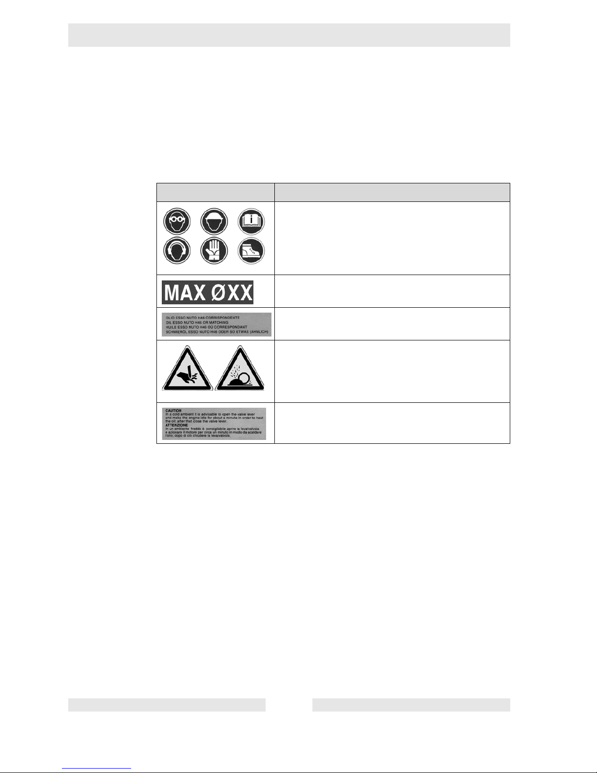
3.10 Labels
Your machine has adhesive labels containing the most important instructions
and safety information.
Make sure that all the labels are kept legible.
Replace any missing or illegible labels.
Labels Description
Wear safety glasses.
Wear hard hat.
Follow operator's manual.
Wear ear protection.
Wear protective gloves.
Wear non-skid, hard-toed shoes.
Max. workpiece diameter.
Only use hydraulic oil of type HLP-ISO-46 (e.g. ESSO
NUTO H46), refer to chapter Technical data.
WARNING
Danger due to cutting.
WARNING
Flying chips.
Warm up machines at temperatures under 5 °C.
Page 17
RCP Safety information
17
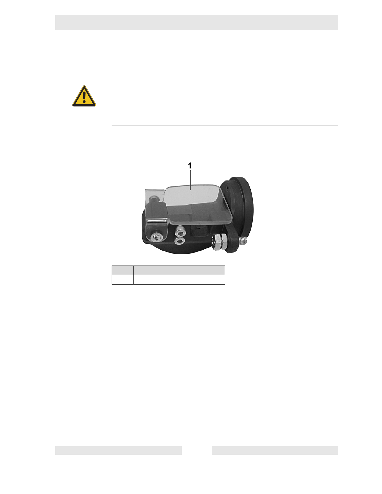
3.11 Safety devices
Protective hood
A protective hood is installed for some machine designs.
WARNING
Danger of injury due to open moving parts.
f Only operate the machine with properly installed and functioning safety de-
vices.
f Do not modify or remove safety devices.
Item Designation
1 Protective hood
Page 18
18
Scope of delivery RCP
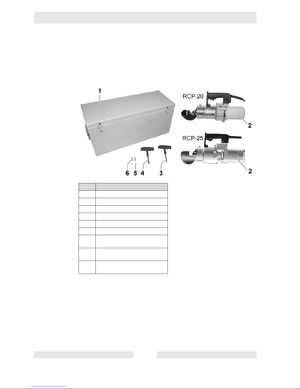
4 Scope of delivery
Machine with cutting head
The machine is delivered fully assembled.
The scope of delivery includes:
Only one cutting machine is included in the scope of deliver.
Item Designation
1Carrying case
2 Cutting machine
3 4 mm Allen wrench
4 6 mm Allen wrench
5 Spring washer (2 pieces)
6 Allen screw (2 pieces)
Operator's Manual (without illustration)
Spare parts catalog (without illustration)
General safety information (without illustration)
Page 19
RCP Description
19
5 Description
5.1 Application
The machine is used for cutting reinforcing steel at construction sites and operations which fabricate reinforcements or process reinforcing iron.
The diameter and tensile strength of the reinforcing steel that may be processed
with the machine are dependent on the machine design. Please refer to the
chapter Technical Data for information concerning your machine.
5.2 Functionality
Principle
An electric motor drives a piston with thrust bolt forwards via a gear pump.
A valve opens at the end of the forward movement and releases the pressure. A
spring presses the piston back in the original position.
In cutting operating the thrust bolt moves a moveable knife against a fixed knife
in the cutting head.
In idle a valve is opened via the pressure release lever. The thrust bolt does not
make a movement.
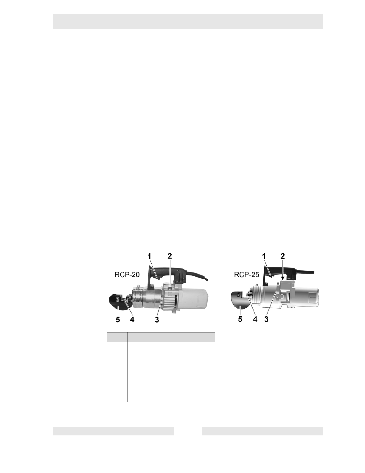
5.3 Components and operator's controls
Item Designation
1 ON/OFF switch
2 Oil filler neck
3 Pressure release lever
4 Stop screw
5 Cutting head
Protective hood (without illustration)
Page 20

20
Description RCP
ON/OFF switch
Switching on the machine
Turn on the machine with the ON/OFF switch. As long as the ON/OFF switch is
pressed, the machine runs in cutting operation or idle, depending on the setting
of the pressure release lever.
Switching off the machine
If the ON/OFF switch is released, the motor stops. In cutting operation the movable knife stops in the current position.
Continuing the cutting movement after stop
If the ON/OFF switch is pressed again after a stop in the cutting operation, the
knife continues its movement until the original position.
Oil filler neck
The oil filler neck is used for filling and emptying the hydraulic oil tank.
A screw plug with sealing ring seals the opening in the oil filler neck.
Pressure release lever
Select operating mode cutting operation or release/idle with the pressure release
lever.
Operating mode cutting operation
When the ON/OFF switch is pressed the machine completes a complete cutting
movement and returns to the original position.
Item Designation
1 Cutting operation ("I")
2 Release/Idle ("0")
Page 21

RCP Description
21
Release/Idle operating mode
When the ON/OFF switch is pressed, the machine runs without performing a cutting movement.
If the knife jams, the cutting movement can be interrupted. For this the machine
has to be switched off and the pressure release lever has to be switched to the
position Release/Idle. The knife moves into the original position.
Cutting head
One fixed knife and one movable knife are installed in the cutting head. Cutting
of the workpiece is done by shearing off.
The cutting head is fastened to the machine with a collar. The cutting head can
be removed. Instead of the cutting head, a bending head (accessory) can be installed on the machine.
Stop screw
The stop screw must be set to the diameter of the workpiece before cutting.
If the stop screw is properly adjusted, the machine cuts the workpiece in a right
angle without canting.
Protective hood
A protective hood is installed on the cutting head for some machine designs.
Close the protective hood before cutting to avoid injuries.
Item Designation
1 Protective hood
Page 22

22
Transport RCP
6 Transport
Transporting the machine
The machine must be transported in the carrying case supplied.
1. Pull the plug from the plug receptacle.
2. Close the protective hood (only installed on some machine designs).
3. Place the machine in the carrying case.
4. Wind up the power cable and place in the carrying case.
5. Store both Allen wrenches in the carrying case.
6. Close carrying case.
7. Place the carrying case on or into a suitable means of transport.
8. Secure the carrying case against falling over and down or sliding.
WARNING
Improper handling can result in injury or serious material damage.
f Read and follow all safety instructions of this operator's manual, see chapter
Safety information.
Page 23

RCP Operation
23
7 Operation
7.1 Prior to starting the machine
After unpacking, the machine is ready for operation.
Plug
The machine comes with a country-specific plug as a standard equipment.
Carrying out checks
f Check if mains or power distribution on the construction site have the correct
operating voltage (see nameplate of the machine or chapter Technical Data).
f Check if mains or power distribution on the constructions site are protected
in accordance with current standards and regulations.
WARNING
Improper handling can result in injury or serious material damage.
f Read and follow all safety instructions of this operator's manual, see chapter
Safety information.
WARNING
Movable knives.
Body parts could be cut off.
f Do not touch the cutting head when the motor is running.
f Close protective hood (if there is one).
Page 24

24
Operation RCP
7.2 Adjusting the machine
Adjusting the stop screw
1. Set the pressure release lever in the Release/Idle position.
2. Open the protective hood (only installed on some machine designs).
3. Loosen jam nut.
4. Place the workpiece on the fixed knife.
5. Set the stop screw so that the workpiece is perpendicular to the axis of the
machine.
6. Tighten the jam nut.
WARNING
Starting the machine.
Danger of injuries from uncontrolled starting of the machine.
f Remove the plug from the plug receptacle before all work on the machine.
Item Designation
1 Movable knife
2Jam nut
3 Stop screw
4 Fixed knife
5Workpiece
Protective hood (without illustration)
Page 25

RCP Operation
25
Selecting the operating mode
f Position the pressure release lever upwards, to start the cutting operation.
f Position the pressure release lever downwards, to start idle.
Item Designation
1 Cutting operation ("I")
2 Release/Idle ("0")
Page 26

26
Operation RCP
7.3 Starting up
Connecting the machine to the power supply
1. If required, connect the machine to a permitted extension cable.
Note: See chapter Technical data for the permitted lengths and cross-section
areas of extension cables.
2. Insert the plug into the plug receptacle.
NOTICE
Worn out knives.
Premature wear of the machine.
f Before beginning work check the sharpness of the knife visually.
f Change worn out knives.
NOTICE
Electrical voltage.
Incorrect voltage can cause damage on the machine.
f Check if the voltage of the current source corresponds with the information
of the machine, see chapter Technical Data.
CAUTION
Electrical voltage.
Danger due to short circuit.
f Check power cable for signs of damage.
Page 27

RCP Operation
27
Running the machine in idle
Note: If the machine is exposed to an ambient temperature under 5 °C, warm
up in idle approx. 1 minute before beginning work on the machine.
1. Set the pressure release lever in the Release/Idle position.
2. Press and hold ON/OFF switch.
The machine runs in idle.
3. Release the ON/OFF switch to turn off.
Item Designation
1 Cutting operation ("I")
2 Release/Idle ("0")
Page 28

28
Operation RCP
Cutting
1. Set pressure release lever in cutting operation position.
2. Open the protective hood (only installed on some machine designs).
3. Guide the workpiece in the cutting head.
4. Close the protective hood.
5. Press and hold ON/OFF switch.
6. If the knife again is in the original position, release the ON/OFF switch.
WARNING
Injuries from insufficiently guided or uncontrolled machine.
Body parts could be cut off.
f If the machine is guided to the workpiece, the machine must always be held
tight with both hands and stand securely.
f If the machine is on a stable foundation, hold the machine with one hand on
the handle and hold the workpiece with the other hand.
NOTICE
Incorrect placement.
Premature wear of the knife.
f Make sure that the stop screw is adjusted to the diameter of the workpiece.
f Make sure that the cutting head and workpiece are perpendicular to each
other.
Item Designation
1 Cutting head
2Workpiece
3 Protective hood
Page 29

RCP Operation
29
7.4 Decomissioning
Switching off the machine
1. Release ON/OFF switch.
2. Set the pressure release lever in the Release/Idle position.
The knife moves into the original position.
3. Pull the plug from the plug receptacle.
Cleaning the machine
1. Free the cutting head of cutting residues with suitable tools.
2. Wipe the housing with a damp and clean cloth.
CAUTION
Electrical voltage.
Danger of electrocution!
f Make sure when cleaning that no water gets into the machine. Do not clean
machine under running water or with a high pressure cleaner.
Page 30

30
Maintenance RCP
8 Maintenance
8.1 Maintenance schedule
Notify your WACKER contact in case of maintenance work which you cannot or
may not complete yourself.
WARNING
Improper handling can result in injury or serious material damage.
f Read and follow all safety instructions of this operator's manual, see chapter
Safety information.
WARNING
Electrical voltage.
Injuries from electrocution.
f Remove the plug from the plug receptacle before all work on the machine.
Task Daily
before
operation
As
required
Every
2 years
Check power cable for perfect
condition – if power cable is
defective, have it replaced.
Visual inspection of all parts
for damage.
Check knife for wear – if necessary, replace knife.
Check screws on machine for
tightness – if necessary, tighten them.
Check the hydraulic oil tank
level for power loss or leaking
hydraulic oil – if necessary
add hydraulic oil.
Change hydraulic oil.
Page 31

RCP Maintenance
31
8.2 Maintenance work
Work in the workshop
Perform maintenance work in a workshop on a workbench. This has the following
benefits:
Protection of the machine of contamination on the construction site.
A level and clean work surface makes work easier.
There is a better overview over small parts and they are not lost as easily.
8.2.1 Visual inspection for damage
Checking the machine
f Check all machine parts for damage or cracks.
WARNING
A damaged machine part or power cable can result in personal injury caused by
electric current.
f Do not operate a damaged machine.
f Have a damaged machine repaired immediately.
Page 32

32
Maintenance RCP
8.2.2 Changing the knife
Performing preparations
1. Pull the plug from the plug receptacle.
2. Open the protective hood (only installed on some machine designs).
Changing the fixed knife
1. Unscrew both fastening screws on the fixed knife.
2. Changing fixed knife.
3. Tighten fixed knife with both fastening screws.
Changing the movable knife
1. Unscrew both fastening screws on the movable knife and remove with the
spring washers.
2. Changing movable knife.
3. Tighten movable knife with both fastening screws and spring washers.
Item Designation
1 Fixed knife
2 Fastening screw (2 pieces)
3 Movable knife
4 Fastening screw with spring
washer (2 pieces)
Page 33

RCP Maintenance
33
8.2.3 Checking the hydraulic oil level
WARNING
Hot hydraulic oil.
Injury by scalding.
f Do not open the screw plug on the oil filler neck as long as the hydraulic oil
is hot.
f Let machine cool off.
CAUTION
Hydraulic oil under pressure.
Squirting hydraulic oil can penetrate the skin.
f Only unscrew the screw plug on the oil filler neck if the thrust bolt is com-
pletely extended.
f Wear safety glasses and protective gloves.
NOTICE
Wrong hydraulic oil.
Damage to machine.
f Only fill with hydraulic oils which are specified for the machine in the chapter
Technical Data.
Page 34

34
Maintenance RCP
Performing preparations
1. Completely extend the thrust bolt. For this press the ON/OFF switch.
2. Pull the plug from the plug receptacle.
3. Remove any dirt around the screw plug.
Checking the hydraulic oil level
1. Place the machine so that the oil filler neck points vertically upward.
2. Open the screw plug on the oil filler neck slowly and carefully.
Hold a cloth over the oil filler neck with the second hand for protection against
escaping hydraulic oil.
3. Unscrew the screw plug on the oil filler neck and remove with sealing ring.
4. Check if the hydraulic oil reaches to the lower edge of the oil filler neck.
If necessary, fill with hydraulic oil up tot the lower edge of the oil filler neck.
5. Screw in the screw plug with sealing ring in the oil filler neck and tighten.
Item Designation
1 Screw plug
2 Oil filler neck
Page 35

RCP Maintenance
35
8.2.4 Changing the hydraulic oil
Change hydraulic oil when it is lukewarm. The oil then flows easier.
Draining out the hydraulic oil
Item Designation
1 Screw plug
2 Oil filler neck
WARNING
Hot hydraulic oil.
Injury by scalding.
f Do not open the screw plug on the oil filler neck as long as the hydraulic oil
is hot.
f Let machine cool off.
CAUTION
Hydraulic oil under pressure.
Squirting hydraulic oil can penetrate the skin.
f Only unscrew the screw plug on the oil filler neck if the thrust bolt is com-
pletely extended.
f Wear safety glasses and protective gloves.
Page 36

36
Maintenance RCP
Note: The work area should be covered with a waterproof sheet to protect
the floor (protection of the environment).
Performing preparations
1. Have a suitable collecting container ready.
2. Completely extend the thrust bolt. For this press the ON/OFF switch.
3. Pull the plug from the plug receptacle.
Draining out the hydraulic oil
1. Place the machine so that the oil filler neck points vertically upward.
2. Open the screw plug on the oil filler neck slowly and carefully.
Hold a cloth over the oil filler neck with the second hand for protection against
escaping hydraulic oil.
3. Unscrew the screw plug on the oil filler neck and remove with sealing ring.
4. Hold the machine with the oil filler neck over the collection container and
drain hydraulic oil.
5. Set the pressure release lever in the Release/Idle position.
6. When the thrust bolt is completely retracted drain the remaining hydraulic oil
in the collection container.
Note: Dispose of hydraulic oil according to the applicable regulations for en-
vironmental protection.
Filling with hydraulic oil
Filling with hydraulic oil
1. Place the machine so that the oil filler neck points vertically upward.
2. Fill with hydraulic oil up to the lower edge of the oil filler neck.
3. Screw in the screw plug with sealing ring in the oil filler neck and tighten.
NOTICE
Wrong hydraulic oil.
Damage to machine.
f Only fill with hydraulic oils which are specified for the machine in the chapter
Tec h nic al D ata .
Page 37

RCP Maintenance
37
Distribute the hydraulic oil
1. Insert the plug into the plug receptacle.
2. Run the machine in cutting operation approx. 3 times back and forth. For this
press the ON/OFF switch.
3. Completely extend the thrust bolt.
4. Pull the plug from the plug receptacle.
Top up with hydraulic oil
1. Place the machine so that the oil filler neck points vertically upward.
2. Unscrew the screw plug on the oil filler neck and remove with sealing ring.
3. Fill with hydraulic oil up to the lower edge of the oil filler neck.
4. Screw in the screw plug with sealing ring in the oil filler neck and tighten.
Page 38

38
Maintenance RCP
8.3 Installing and removing the cutting head
Removing the cutting head
1. Unscrew both fastening screws on the movable knife and remove with the
spring washers.
2. Removing the movable knife.
3. Unscrew the fastening screw on the collar.
4. Remove collar.
5. Remove cutting head towards the front.
WARNING
Starting the machine.
Danger of injuries from uncontrolled starting of the machine.
f Remove the plug from the plug receptacle before all work on the machine.
Item Designation
1 Fastening screw
2 Movable knife
3 Cutting head
4 Fastening screw (2 pieces)
5 Collar
Page 39

RCP Maintenance
39
Installing the cutting head
Sliding the cutting head
1. Place the cutting head on the machine so that when sliding on, the locating
pin on the cutting head engages into the hole on the machine.
2. Slide the cutting head to the stop.
Item Designation
1 Machine
2Bore
3 Locating pin
4 Cutting head
Page 40

40
Maintenance RCP
Fastening the cutting head
1. Put the collar on.
2. Turn and tighten the fastening screw on the collar.
3. Tighten movable knife with both fastening screws and spring washers.
Item Designation
1 Fastening screw
2 Movable knife
3 Fastening screw (2 pieces)
4 Collar
Page 41

RCP Troubleshooting
41
9 Troubleshooting
Potential faults, their causes and the respective remedies are listed in the following table.
Notify your WACKER contact in case of malfunctions you cannot or may not remedy yourself.
Malfunction Cause Remedy
Workpiece jammed or slipped. Stop screw is set incorrectly. Adjust the stop screw.
Machine not in operation. Input voltage too high or too
low.
Provide correct voltage; if necessary use an extension cable
with sufficient cross section.
Power cable interrupted. Check power cable, have it re-
placed if defective.
Thrust bolt moves out incompletely or unevenly.
Insufficient hydraulic oil in the
hydraulic oil tank.
Check oil level, fill with hydraulic oil if necessary.
Cold hydraulic oil. Warm up machine for approx.
1 minute.
Thrust bolt does not move back
completely.
Dirt and cutting residue in the
cutting head.
Clean cutting head.
Hydraulic oil is leaking out. Sealing ring on the oil filler neck
is damaged.
Check sealing ring, change if
necessary.
Leak on the hydraulic cylinder,
hydraulic oil tank or screwed
connections.
Have the machine repaired.
Page 42

42
Disposal RCP
10 Disposal
10.1 Disposal of the machine
Your machine contains many valuable raw materials which should be disposed
and recycled in an environmentally friendly manner.
During disposal of the machine observe the country-specific rules and regulations, e.g. the European Directive for obsolete electrical and electronic devices.
Do not dispose of the machine in household rubbish. It
must be disposed at a recycling facility.
Page 43

RCP Accessories
43
11 Accessories
11.1 General notes
The following accessories are offered for the machine.
For more information on the individual accessories, visit the following website:
www.wackergroup.com.
11.2 Bending head
11.2.1 Safety
Proper use
The bending head may only be used for bending reinforcing steel. The bending
head must be installed on a machine with interchangeable head, which is suitable for it.
The diameter and tensile strength of the reinforcing steel that may be processed
with the machine are dependent on the machine design. Please refer to the
chapter Technical Data for information concerning your machine.
Worksites are construction sites and operations which fabricate reinforcements
or process reinforcing iron.
The beinding head must not be used for processing the following materials:
Wires
Pipes
Plastics
Wood
Its proper use also includes the observance of all instructions contained in this
operator's manual as well as complying with the required service and maintenance instructions.
Any other use is regarded as improper. Any damage resulting from improper use
will void the warranty and the liability on behalf of the manufacturer. The operator
assumes full responsibility.
Page 44

44
Accessories RCP
11.2.2 Scope of delivery
11.2.3 Description
Application
The bending head can be installed on a machine with interchangeable head. In
the installed condition the bending head can be used to bend reinforcing steel.
Using the two exchangeable molding pieces, two different bending radii can be
set.
Item Designation
1 Fastening screw
2 Bending head
3 Fastening screw
4 Spring washer
5Nut
6 Movable die
7 Small molding piece
8 Large molding piece
Page 45

RCP Accessories
45
Functionality
The workpiece must be placed between the molding piece and the die for bending.
In the forward movement the die bends the workpiece around the molding piece.
At the end of the reverse movement the die releases the workpiece.
The bending angle is dependent on the path that the die makes during the forward movement.
If the die moves completely forward, the smallest possible bending angle is
made.
Any desired larger angle can be bent when the forwards movement is interrupted
by releasing the ON/OFF switch. If the pressure release lever is set in the Release/Idle position, the die returns to the original position.
Components and their function
The molding piece is permanently screwed onto the bending head. The size of
the molding piece determines the bending radius.
The die is permanently screwed onto thrust bolt of the machine and moves with
the thrust bolt.
Item Designation
1 Molding piece
2 Movable die
Page 46

46
Accessories RCP
11.2.4 Operation
Installing the bending head
Before the bending head can be installed on the machine, the cutting head must
be removed, see 8.3 Installing and removing the cutting head (page 38).
Sliding the bending head
1. Place the bending head on the machine so that when sliding it on, the locating pin on the bending head engages into the bore on the machine.
2. Slide the bending head to the stop.
WARNING
Starting the machine!
Danger of injury with uncontrolled start up.
f Before all work on the machine and on accessories, remove the plug from
the plug receptacle.
Item Designation
1 Machine
2Bore
3 Locating pin
4 Bending head
Page 47

RCP Accessories
47
Fastening the bending head
1. Put the collar on.
2. Turn and tighten the fastening screw on the collar.
3. Tighten the die with the fastening screw, spring washer and nut onto the
thrust bolt.
Item Designation
1 Collar
2Nut
3 Die
4 Fastening screw
5 Thrust bolt
6 Fastening screw
Page 48

48
Accessories RCP
Removing the bending head
1. Unscrew the fastening screw on the thrust bolt and remove with spring washer and nut.
2. Remove die.
3. Unscrew the fastening screw on the collar.
4. Remove collar.
5. Remove bending head towards the front.
Item Designation
1 Collar
2Nut
3 Die
4 Fastening screw
5 Thrust bolt
6 Fastening screw
Page 49

RCP Accessories
49
Changing the molding piece
1. Screw out the fastening screw.
2. Remove molding piece.
3. Place another molding piece on. When doing so make sure that the slanted
edge on the molding piece is aligned downwards.
4. Tighten the molding piece with the fastening screw.
Bending the workpiece
Item Designation
1 Molding piece
2 Fastening screw
WARNING
Movable tool.
Body parts could be crushed.
f Do not touch the bending head when the motor is running.
WARNING
Injuries from insufficiently guided or uncontrolled machine.
Body parts could be crushed.
f Hold the machine with one hand and guide the workpiece into the bending
head with the other hand.
Page 50

50
Accessories RCP
1. Set pressure release lever in cutting operation position (here: bending operation).
2. Guide workpiece between the molding piece and the die in the bending head.
3. Press and hold the ON/OFF switch until the desired bending angle has been
reached.
If the smallest possible bending angle should be made:
Hold down the ON/OFF switch until the die is completely retracted.
If the another bending angle should be made:
Release the ON/OFF switch when the desired bending angle is reached
and set the pressure release lever into the Release/Idle position.
4. When the die has completely retracted, remove the workpiece from the bending head.
Item Designation
1Workpiece
2 Bending head
Page 51

RCP Accessories
51
11.2.5 Technical data for accessories
P-20/25 bending head
Designation Unit HB-20 HB-25
Installation on the cutting machine
RCP-20 RCP-25
Length x Width x Height mm 190 x 125 x 90 220 x 290 x 130
Weight kg 5.3 8.5
Min. bending radius on the inside
of the workpiece
mm 18
Bending angle ° 180-65* 180-80*
* The smallest possible bending angle depends on the diameter and tensile strength of
the workpiece.
Max. allowable tension strength
of the workpiece
N/mm
2
750
Max. allowable diameter workpiece
mm 20 25
Page 52

52
Technical data RCP
12 Technical data
12.1 RCP-20/25 - 230
Designation Unit RCP-20 RCP-25
Item no. 0610201 0610203
Length x Width x Height mm (in) 385 x 180 x 240
(15.2 x 7.1 x 9.5)
405 x 170 x 250
(15.9 x 6.7 x 9.8)
Operating weight kg (lb) 13.7 (30.2) 13.9 (30.6)
Rated voltage V 230 1~
Rated frequency Hz 50
Rated power consumption W 1,400
Rated current consumption A 6.8
Class rating II
Protection class IP 20
Engine speed rpm 14,000
Operating temperature °C (°F) -20 to +50 (-4 to +122)
Hydraulic oil, specification HLP-ISO-46
Hydraulic oil, fill quantity l (gal) 0.6 (0.2)
Max. compressive force t 30 40
Opening/closing time of the tool s 5 5.5
Max. allowable tension strength
of the workpiece
N/mm
2
750
Max. allowable diameter workpiece
mm (in) 20 (0.79) 25 (0.98)
Protective hood — —
Sound power level L
WA
in cutting
operation
dB(A) 102
Sound pressure level at
operator's station L
PA
in cutting
operation
dB(A) 94
Page 53

RCP Technical data
53
12.2 RCP-20/25 - 115
Designation Unit RCP-20 RCP-25
Item no. 0610215 0610216
Length x Width x Height mm (in) 385 x 180 x 240
(15.2 x 7.1 x 9.5)
405 x 170 x 250
(15.9 x 6.7 x 9.8)
Operating weight kg (lb) 13.7 (30.2) 13.9 (30.6)
Rated voltage V 115 1~
Rated frequency Hz 50
Rated power consumption W 1,300
Rated current consumption A 11.0
Class rating II
Protection class IP 20
Engine speed rpm 14,000
Operating temperature °C (°F) -20 to +50 (-4 to +122)
Hydraulic oil, specification HLP-ISO-46
Hydraulic oil, fill quantity l (gal) 0.6 (0.2)
Max. compressive force t 30 40
Opening/closing time of the tool s 5 5.5
Max. allowable tension strength
of the workpiece
N/mm
2
750
Max. allowable diameter workpiece
mm (in) 20 (0.79) 25 (0.98)
Protective hood
Sound power level LWA in cutting
operation
dB(A) 102
Sound pressure level at
operator's station L
PA
in cutting
operation
dB(A) 94
Page 54

54
Technical data RCP
12.3 RCP-20/25 - 120
Designation Unit RCP-20 RCP-25
Item no. 0610202 0610204
Length x Width x Height mm (in) 385 x 180 x 240
(15.2 x 7.1 x 9.5)
405 x 170 x 250
(15.9 x 6.7 x 9.8)
Operating weight kg (lb) 13.7 (30.2) 13.9 (30.6)
Rated voltage V 120 1~
Rated frequency Hz 60
Rated power consumption W 1,300
Rated current consumption A 11.0
Class rating II
Protection class IP 20
Engine speed rpm 14,000
Operating temperature °C (°F) -20 to +50 (-4 to +122)
Hydraulic oil, specification HLP-ISO-46
Hydraulic oil, fill quantity l (gal) 0.6 (0.2)
Max. compressive force t 30 40
Opening/closing time of the tool s 5 5.5
Max. allowable tension strength
of the workpiece
N/mm
2
750
Max. allowable diameter workpiece
mm (in) 20 (0.79) 25 (0.98)
Protective hood
Sound power level LWA in cutting
operation
dB(A) 102
Sound pressure level at
operator's station L
PA
in cutting
operation
dB(A) 94
Page 55

RCP Technical data
55
12.4 Extension cable
Refer to the following table for the required cross-section area of cable for a designated extension.
Note: Refer to the nameplate or the chapter Technical data (via the item
number) for the type designation and voltage rating of your machine.
Volta ge
[V]
Extension
[m]
Cross-section
area of cable
[mm
2
]
115 < 27 1.5
< 45 2.5
< 72 4
< 107 6
120 < 28 1.5
< 47 2.5
< 75 4
< 111 6
230 < 88 1.5
< 146 2.5
Page 56

56
Technical data RCP
Extension cable for the US market:
Example
You utilize a RCP-20/230 and want to use an extension cable with a length of
50 m (164 ft).
The machine has an input voltage of 230 V.
According to the table, the extension cable must feature a cross-section area of
1.5 mm
2
(AWG 16).
Machine Voltage
[V]
Extension
[ft]
Cross-section
area of cable
[AWG]
RCP-20
RCP-25
115 < 79 16
< 125 14
< 197 12
< 308 10
120 < 82 16
< 128 14
< 203 12
< 322 10
230 < 253 16
< 400 14
< 492 12
Page 57

EC Declaration of Conformity
Wacker Construction Equipment AG, Preußenstraße 41, 80809 München certifies that the
construction machines:
Category
Cutting machine with interchangeable head
fulfill the requirements of the following directives:
98/37/EC
2004/108/EC
EN 61000
2006/95/EC
Typ e RCP-20 RCP-25
Machine type number 0610201
0610202
0610215
0610203
0610204
0610216
Operating weight kg 13.7 13.9
Dr. Stenzel
Head of Research and Development
Page 58

Page 59

Prüf- und Zertifizierungsinstitut
VERBAND DER ELEKTROTECHNIK
ELEKTRONIK INFORMATIONSTECHNIK e.V.
C E R T I F I C A T E
Registration-Number: 6236/QM/06.97
This is to certify that the company
Wacker Construction Equipment AG
Wacker-Werke GmbH & Co. KG
at the following locations
Head Office Munich
Preußenstraße 41
80809 Munich
Production plant Reichertshofen
Karlsfeld logistics centre
Sales regions with all branches all over Germany
has implemented and maintains a
Qality Management System for the following scope:
Machine manufacture
Construction machines
This Q System complies with the requirements of
DIN EN ISO 9001:2000
and the requirements of the German and international Road Traffic Act.
This Certificate is valid until 2009-06-05.
VDE Testing and Certification Institute
Certification
Date: 2006-05-30
63069 Offenbach, Merianstraße 28
Telefon: +49 (0) 69 83 06-0, Telefax: +49 (0) 69 83 06-555
E-Mail: vde-institut@vde.com
, http://www.vde-institut.com
The VDE Testing and Certification Institute is accredited by DAR Accreditation
Bodies according to DIN EN ISO 17020 and DIN EN ISO 45012 and notified in the EU
under ID.No. 0366.
TGA-ZM-09-92-00
KBA-ZM-A 00021-97
DIN EN ISO 9001 Certificate
Page 60

Wacker Construction Equipment AG, Preußenstraße 41, 80809 München – Deutschland – Tel.: +49-(0)89-354 02-0 – Fax: +49-(0)89-354 02-390
Wacker Corporation – P.O. Box 9007 – Menomonee Falls, WI 53052-9007 – USA – Tel.: +1(1)262-255-0500 – Fax: +1(1)262-255-0550 – Support: 800-770-0957
Wacker Machinery (HK) Ltd.– Skyline Tower, Suite 2303, 23/F – 39 Wang Kwong Road, Kowloon Bay – Hong Kong – Tel.: +852-3188-5506, Fax: +852-2406-6021
Page 61

Page 62

 Loading...