

Page 1
0171882en 002
0708
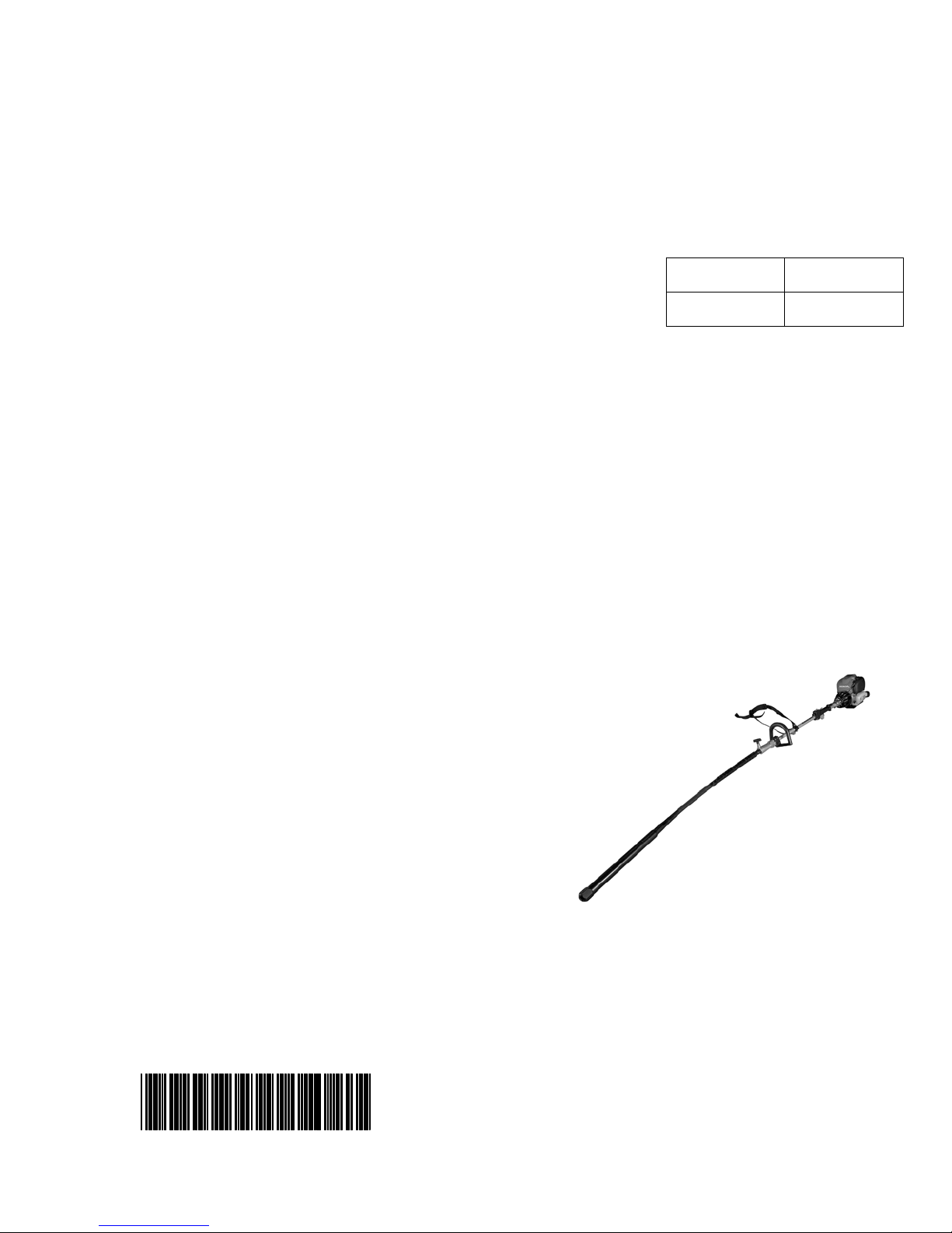
Handheld Gas
Vibrator
PV 35A
OPERATOR’S MANUAL
0171882EN
Page 2

Page 3

Table of Contents PV 35A
1. Foreword 4
2. Safety Information 5
2.1 Laws Pertaining to Spark Arresters .......................................................5
2.2 Operating Safety ...................................................................................6
2.3 Operator Safety while using Internal Combustion Engines ...................7
2.4 Service Safety .......................................................................................8
2.5 Label Locations ...................................................................................10
2.6 Warning and Informational Labels .......................................................11
3. Operation 12
3.1 Application ...........................................................................................12
3.2 Recommended Fuel ............................................................................12
3.3 Starting the Engine ..............................................................................12
3.4 Stopping the Engine ............................................................................13
3.5 Operating the Machine ........................................................................14
3.6 When Vibration Is Complete ................................................................15
3.7 Tumble Cage Accessory .....................................................................16
4. Maintenance 18
4.1 Periodic Maintenance Schedule ..........................................................18
4.2 Engine Oil ............................................................................................19
4.3 Air Cleaner ..........................................................................................20
4.4 Spark Plug ...........................................................................................21
4.5 Head and Shaft Disassembly ..............................................................22
4.6 Storage ................................................................................................26
4.7 Troubleshooting ...................................................................................26
5. Technical Data 27
5.1 Engine .................................................................................................27
5.2 Power Unit ...........................................................................................28
5.3 Sound and Vibration Data................................................................... 28
wc_bo0171882en_002TOC.fm 3
Page 4

WARNING
1 Foreword
Foreword
CALIFORNIA
Proposition 65 Warning:
Engine exhaust, some of its constituents, and certain vehicle
components, contain or emit chemicals known to the State of
California to cause cancer and birth defects or other reproductive
harm.
This manual provides information and procedures to safely operate
and maintain this Wacker Neuson model. For your own safety and
protection from injury, carefully read, understand and observe the
safety instructions described in this manual.
Keep this manual or a copy of it with the machine. If you lose this
manual or need an additional copy, please contact Wacker Neuson
Corporation. This machine is built with user safety in mind; however,
it can present hazards if improperly operated and serviced. Follow
operating instructions carefully! If you have questions about operating
or servicing this equipment, please contact Wacker Neuson
Corporation.
The information contained in this manual was based on machines in
production at the time of publication. Wacker Neuson Corporation
reserves the right to change any portion of this information without
notice.
All rights, especially copying and distribution rights, are reserved.
Copyright 2008 by Wacker Neuson Corporation.
No part of this publication may be reproduced in any form or by any
means, electronic or mechanical, including photocopying, without
express written permission from Wacker Neuson Corporation.
Any type of reproduction or distribution not authorized by Wacker
Neuson Corporation represents an infringement of valid copyrights
and will be prosecuted. We expressly reserve the right to make
technical modifications, even without due notice, which aim at
improving our machines or their safety standards.
wc_tx000001gb.fm 4
Page 5
Safety Information PV 35A
2. Safety Information
This manual contains DANGER, WARNING, CAUTION, NOTICE and
NOTE callouts which must be followed to reduce the possibility of
personal injury, damage to the equipment, or improper service.
This is the safety alert symbol. It is used to alert you to potential
personal injury hazards. Obey all safety messages that follow this
symbol to avoid possible injury or death.
DANGER indicates a hazardous situation which, if not avoided, will
result in death or serious injury.
DANGER
WARNING indicates a hazardous situation which, if not avoided, could
result in death or serious injury.
WARNING
CAUTION indicates a hazardous situation which, if not avoided, could
result in minor or moderate injury.
CAUTION
NOTICE: Used without the safety alert symbol, NOTICE indicates a
situation which, if not avoided, could result in property damage.
Note: Contains additional information important to a procedure.
2.1 Laws Pertaining to Spark Arresters
Notice: State Health Safety Codes and Public Resources Codes
specify that in certain locations spark arresters be used on internal
combustion engines that use hydrocarbon fuels. A spark arrester is a
device designed to prevent accidental discharge of sparks or flames
from the engine exhaust. Spark arresters are qualified and rated by
the United States Forest Service for this purpose.
In order to comply with local laws regarding spark arresters, consult
the engine distributor or the local Health and Safety Administrator.
wc_si000224gb.fm 5
Page 6

PV 35A Safety Information
2.2 Operating Safety
Familiarity and proper training are required for the safe operation of the
machine. Machines operated improperly or by untrained personnel
can be dangerous. Read the operating instructions contained in both
WARNING
2.2.1 NEVER allow anyone to operate this equipment without proper
2.2.2 NEVER touch the engine or muffler while the engine is on or
2.2.3 NEVER use accessories or attachments that are not recommended by
2.2.4 NEVER leave the machine running unattended.
this manual and the Engine Manual and familiarize yourself with the
location and proper use of all controls. Inexperienced operators should
receive instruction from someone familiar with the machine before
being allowed to operate it.
training. People operating this equipment must be familiar with the
risks and hazards associated with it.
immediately after it has been turned off. These areas get hot and may
cause burns.
Wacker. Damage to equipment and injury to the user may result.
2.2.5 NEVER operate this machine in applications for which it is not
intended.
2.2.6 ALWAYS wear protective clothing appropriate to the job site when
operating the machine.
2.2.7 ALWAYS remain aware of moving parts and keep hands, feet, and
loose clothing away from the moving parts of the machine.
2.2.8 ALWAYS read, understand, and follow procedures in the Operator’s
Manual before attempting to operate the machine.
2.2.9 ALWAYS store the machine properly when it is not being used. The
machine should be stored in a clean, dry location out of the reach of
children.
2.2.10 ALWAYS close fuel valve on engines equipped with one when
machine is not being operated.
2.2.11 ALWAYS operate machine with all safety devices and guards in place
and in working order. DO NOT modify or defeat safety devices. DO
NOT operate machine if any safety devices or guards are missing or
inoperative.
2.2.12 ALWAYS be sure operator is familiar with proper safety precautions
and operation techniques before using machine.
wc_si000224gb.fm 6
Page 7

Safety Information PV 35A
2.3 Operator Safety while using Internal Combustion Engines
Internal combustion engines present special hazards during operation
and fueling. Read and follow the warning instructions in the engine
Owner’s Manual and the safety guidelines below. Failure to follow the
DANGER
2.3.1 DO NOT run the machine indoors or in an enclosed area such as a
2.3.2 DO NOT smoke while operating the machine.
2.3.3 DO NOT smoke when refueling the engine.
2.3.4 DO NOT refuel a hot or running engine.
2.3.5 DO NOT refuel the engine near an open flame.
2.3.6 DO NOT spill fuel when refueling the engine.
2.3.7 DO NOT run the engine near open flames.
warnings and safety standards could result in severe injury or death.
deep trench unless adequate ventilation, through such items as
exhaust fans or hoses, is provided. Exhaust gas from the engine
contains poisonous carbon monoxide gas; exposure to carbon
monoxide can cause loss of consciousness and may lead to death.
2.3.8 ALWAYS refill the fuel tank in a well-ventilated area.
2.3.9 ALWAYS replace the fuel tank cap after refueling.
2.3.10 ALWAYS check the fuel lines and the fuel tank for leaks and cracks
before starting the engine. Do not run the machine if fuel leaks are
present or the fuel lines are loose.
wc_si000224gb.fm 7
Page 8

PV 35A Safety Information
2.4 Service Safety
A poorly maintained machine can become a safety hazard! In order
for the machine to operate safely and properly over a long period of
time, periodic maintenance and occasional repairs are necessary.
WARNING
2.4.1 DO NOT attempt to clean or service the machine while it is running.
Rotating parts can cause severe injury.
2.4.2 DO NOT crank a flooded engine with the spark plug removed on
gasoline-powered engines. Fuel trapped in the cylinder will squirt out
the spark plug opening.
2.4.3 DO NOT test for spark on gasoline-powered engines if the engine is
flooded or the smell of gasoline is present. A stray spark could ignite
the fumes.
2.4.4 DO NOT use gasoline or other types of fuels or flammable solvents to
clean parts, especially in enclosed areas. Fumes from fuels and
solvents can become explosive.
2.4.5 ALWAYS keep the area around the muffler free of debris such as
leaves, paper, cartons, etc. A hot muffler could ignite the debris and
start a fire.
2.4.6 ALWAYS replace worn or damaged components with spare parts
designed and recommended by Wacker Neuson Corporation.
2.4.7 ALWAYS disconnect the spark plug on machines equipped with
gasoline engines, before servicing, to avoid accidental start-up.
2.4.8 ALWAYS keep the machine clean and labels legible. Replace all
missing and hard-to-read labels. Labels provide important operating
instructions and warn of dangers and hazards.
wc_si000224gb.fm 8
Page 9

Safety Information PV 35A
Notes:
wc_si000224gb.fm 9
Page 10

PV 35A Safety Information
2.5 Label Locations
wc_si000224gb.fm 10
wc_gr004853
Page 11

Safety Information PV 35A
2.6 Warning and Informational Labels
Wacker Neuson machines use international pictorial labels where
needed. These labels are described below:
Label Meaning
DANGER!
Engines emit carbon monoxide; operate only
in well-ventilated area. Read the Operator’s
Manual.
No sparks, flames, or burning objects near the
machine. Shut off the engine before refueling.
WARNING!
Hot surface!
WARNING!
Always wear hearing and eye protection when
operating this machine.
A nameplate listing the model number, item
number, revision number, and serial number is
attached to each unit. Please record the
information found on this plate so it will be
available should the nameplate become lost or
damaged. When ordering parts or requesting
service information, you will always be asked
to specify the model number, item number,
revision number, and serial number of the unit.
wc_si000224gb.fm 11
Page 12

PV 35A Operation
3. Operation
3.1 Application
This machine is intended for on-site vibration of concrete for
foundations, walls, columns, slab work, etc. The self-contained design
allows free movement about the jobsite without the restrictions of an
electrical cord.
3.2 Recommended Fuel
The engine requires regular grade unleaded gasoline. Use only fresh,
clean gasoline. Gasoline containing water or dirt will damage fuel
system. Consult engine owner’s manual for complete fuel
specifications.
3.3 Starting the Engine
See Graphic: wc_gr004492
3.3.1 If engine is cold, move the choke lever (a) to the CLOSED position
(a1). If engine is hot, set the choke to the OPEN position (a2).
3.3.2 Press the priming bulb (b) repeatedly until fuel can be seen in the clear
plastic fuel return tube (c).
3.3.3 Turn the engine switch to the ON position (d1).
3.3.4 Pull the starter grip (e) lightly until you feel resistance, then pull briskly.
Return the starter grip gently.
3.3.5 Gradually open the choke as the engine warms up (a2).
3.3.6 Open the throttle fully to operate equipment. (See “Operating the
Machine” for more information.)
wc_tx000754gb.fm 12
Page 13

Operation PV 35A
d2
d1
3.4 Stopping the Engine
See Graphic: wc_gr004492
3.4.1 Reduce engine RPM to idle by moving throttle completely to right.
3.4.2 Turn engine switch to OFF (d2).
wc_gr004492
wc_tx000754gb.fm 13
Page 14

PV 35A Operation
3.5 Operating the Machine
The PV 35A vibrator features a unique pendulous design. This design
causes the vibrator to rattle and possibly feel off-center in rotation. This
is normal; the vibrator is not broken or damaged.
To prepare the machine for operation:
See graphic: wc_gr004498
3.5.1 Make sure that the engine has oil in it.
3.5.2 Turn the quick-disconnect coupler (a) clockwise and insert the vibrator
shaft (b). Once the vibrator shaft is inserted, turn the quick-disconnect
coupler counter-clockwise to lock the vibrator in position.
a
b
c
wc_gr004498
To operate the machine:
3.5.1 Start the engine and allow it to warm up for approximately 5–7 minutes.
3.5.2 Bring the engine up to full throttle (approximately 9000 rpm) by
squeezing the trigger (c).
3.5.3 Activate the vibrator action by striking the side of the vibrator head
against a solid object.
NOTE: Avoid slamming the nose of the vibrator head against solid
objects. Head-on impacts may damage the machine.
3.5.4 Begin vibrating by placing the vibrator head into the concrete.
NOTE: Do not submerge the head and shaft above the coupler
assembly.
wc_tx000754gb.fm 14
Page 15

Operation PV 35A
Operating tips:
3.5.1 NEVER turn the vibrator off while it is submerged in the concrete.
3.5.2 During use, insert the head quickly into the mix and then pull it out
slowly. Rapid removal is the main cause of poor concrete
consolidation. For best results, submerge head completely and try to
establish a symmetrical pattern for inserting and removing the head.
3.5.3 When moving around the jobsite, do not drag the vibrator head and
shaft on the ground.
3.5.4 Avoid touching forms and rebars when inserting the vibrator head into
the mix. This can transmit vibration to other areas of the mix which may
already be setting.
3.5.5 When the vibrator is out of the concrete for extended periods of time,
allow the engine to return to idle speed or simply turn the machine off .
3.6 When Vibration Is Complete
When you are finished using the vibrator:
3.6.1 Bring the engine RPM down to idle speed.
3.6.2 Lift the vibrator head out of the concrete
3.6.3 Shut off the engine by turning the engine switch to the OFF position.
3.6.4 Disconnect the vibrator shaft from the engine.
3.6.5 Rinse the vibrator head and shaft thoroughly with clean water. Do not
allow concrete to harden on these components.
3.6.6 See “Maintenance” chapter for extended storage procedures.
wc_tx000754gb.fm 15
Page 16

PV 35A Operation
7
3.7 Tumble Cage Accessory
See graphic: wc_gr004867
An optional “Tumble Cage” assembly is available to protect the
unit from accidental dropping. The cage is NOT intended to
protect the unit from misuse, mishandling, or abuse. Contact
your Wacker Neuson dealer for ordering information.
wc_gr00486
wc_tx000754gb.fm 16
Page 17

Operation PV 35A
Notes:
wc_tx000754gb.fm 17
Page 18

PV 35A Maintenance
4. Maintenance
4.1 Periodic Maintenance Schedule
The chart below lists basic machine and engine maintenance. Refer to
your engine operator’s manual for additional information on engine
maintenance.
Check fuel level.
Check engine oil level.
Inspect air filter. Replace as needed.
Change engine oil.
Clean air cleaner.
Check engine cooling fins
(if equipped).
Check and clean spark plug.
Check fuel filter.
Clean fuel tank.
Clean spark arrester (if equipped).
Check and adjust valve clearance.
Daily
before
starting
After
first
10 hrs.
After
first
25 hrs.
Every
50
hrs.
Every
100
hrs.
Every
300
hrs.
wc_tx000755gb.fm 18
Page 19

Maintenance PV 35A
4.2 Engine Oil
See Graphic: wc_gr000020
4.2.1 Drain the oil while the engine is still warm.
4.2.2 Remove the oil filler plug (a) and the drain plug (b) to drain the oil.
Note: In the interests of environmental protection, place a plastic sheet
and a container under the machine to collect any liquid that drains off.
Dispose of this liquid in accordance with environmental protection
legislation.
4.2.3 Install the drain plug.
4.2.4 Fill the engine crankcase with the recommended oil up to the level of
the plug opening (c). See section Technical Data for oil quantity and
type.
4.2.5 Install the oil filler plug.
wc_tx000755gb.fm 19
wc_gr000022
Page 20

PV 35A Maintenance
4.3 Air Cleaner
See Graphic: wc_gr004366
The engine is equipped with a foam element air cleaner. Service the
air cleaner frequently to prevent carburetor malfunction.
NOTICE: NEVER run engine without the air cleaner. Severe engine
damage will occur.
NEVER use gasoline or other types of low flash point solvents for
cleaning the air cleaner. A fire or explosion could result.
WARNING
To service the air cleaner (GX35 engine):
4.3.1 Press the latch tab (a) on top of the air cleaner cover (b) and remove
the air cleaner cover. Remove the foam element (c) and inspect it for
holes or tears. Replace the element if damaged.
4.3.2 Wash the element in a solution of mild detergent and warm water.
Rinse thoroughly in clean water. Allow the element to dry thoroughly.
Soak the element in clean engine oil and squeeze out excess oil. The
engine will smoke when started if too much oil is left in the foam.
4.3.3 Using a moist rag, wipe dirt from the air cleaner body and cover. Be
careful to prevent dirt from entering the carburetor.
4.3.4 Re-install the filter element and air cleaner cover.
a
b
a
c
wc_tx000755gb.fm 20
wc_gr004366
Page 21

Maintenance PV 35A
4.4 Spark Plug
See Graphic: wc_gr000028
Clean or replace the spark plug as needed to ensure proper operation.
Refer to your engine operator’s manual.
The muffler becomes very hot during operation and remains hot for a
while after stopping the engine. Do not touch the muffler while it is hot.
WARNING
Note: Refer to section Technical Data for the recommended spark
plug type and the electrode gap setting.
4.4.1 Remove the spark plug and inspect it.
4.4.2 Replace the spark plug if the insulator is cracked or chipped.
4.4.3 Clean the spark plug electrodes with a wire brush.
4.4.4 Set the electrode gap (a).
4.4.5 Tighten the spark plug securely.
NOTICE: A loose spark plug can become very hot and may cause
engine damage.
wc_tx000755gb.fm 21
Page 22

PV 35A Maintenance
4.5 Head and Shaft Disassembly
See graphic: wc_gr005377
c
b
a
j
h
q
r
k
m
f
g
e
o
v
t
l
n
p
d
s
u
w
x
4.5.1 Disassembling the flexible casing and core:
4.5.1.1 Place the vibrator head assembly (a) in a vise equipped
with a set of “V” jaws.
4.5.1.2 Unscrew the casing assembly (b) from the vibrator head
assembly using a 32mm wrench or pipe wrench.
Note: Threads on the casing assembly are left-hand and require
uniform heat to remove.
4.5.1.3 Pull the casing assembly away from the head and core
assembly (c).
4.5.1.4 Unscrew the core assembly from the head assembly using
a 12mm wrench or adjustable wrench.
Note: Use an additional wrench or pliers to hold the shaft joint (d) while
unscrewing the core assembly.
wc_gr005377
wc_tx000755gb.fm 22
Page 23

Maintenance PV 35A
4.5.2 Lubricating the core assembly:
4.5.2.1 A light coat of grease (i.e. Dubois TPG, Wacker Neuson
part number 0161045) should be applied to the entire
length of the core assembly. Apply grease to the core
assembly at least twice a year.
4.5.3 Disassembling the vibrator head assembly:
4.5.3.1 Place the vibrator head assembly in a vise equipped with a
set of “V” jaws.
4.5.3.2 Unscrew the hose connector (k) from the bearing case (l)
using a 38mm wrench or a large pipe wrench.
Note: Threads on the casing assembly are left-hand and require
uniform heat to remove.
4.5.3.3 Remove the flex joint (m) from the drive joint (u).
4.5.3.4 Unscrew the bearing case from the body (n) using a 41mm
wrench or a large pipe wrench.
4.5.3.5 Unscrew the nose (o) from the body using a 1-1/4" wrench
or a large pipe wrench.
Note: Threads on the casing assembly are left-hand and require
uniform heat to remove.
4.5.4 Disassembling the hose connector assembly:
4.5.4.1 Remove the top snap ring (p) using snap-ring pliers.
4.5.4.2 Remove the shaft joint (d) from the hose connector (k).
4.5.4.3 Remove the bottom snap ring (q).
4.5.4.4 Unscrew the drive joint (r) from the shaft joint using a 1/4"
square rachet (or metric equivalent). Hold the shaft joint
with a 12mm wrench or pliers.
Note: Threads are right-hand.
wc_tx000755gb.fm 23
Page 24

PV 35A Maintenance
See graphic: wc_gr005377
c
b
a
j
h
q
r
k
m
f
g
e
o
v
t
l
n
p
d
s
u
w
x
4.5.5 Disassembling the eccentric assembly:
4.5.5.1 Place the bearing case (l) in a standard vise with the male
threads positioned upward.
4.5.5.2 Using a hammer, gently tap the upper portion of the
eccentric weight (t).
Note: Place your hand on the underside of the bearing case to catch
the eccentric weight as it comes apart from the bearing case.
4.5.5.3 Unscrew the drive joint (u) from the eccentric weight using
a 1/4” square ratchet.
4.5.5.4 Remove the bearing (v), spacer (w), and oil seal (x) from
the eccentric.
wc_gr005377
4.5.6 Reassembling the head and shaft:
Perform steps 4.5.1 through 4.5.5 in the reverse order.
wc_tx000755gb.fm 24
Page 25

Maintenance PV 35A
4.5.7 Maintenance notes:
4.5.7.1 Bearing (v) and oil seal (x) should be replaced after 200
hours of use. The bearing must be greased with Orelube G1/3 grease or equivalent.
4.5.7.2 Inspect the angled end of the eccentric weight (t) for wear.
If visible wear is present, the eccentric weight should be
replaced.
4.5.7.3 Inspect the nose (o) for wear. If visible wear is present, the
nose should be replaced.
wc_tx000755gb.fm 25
Page 26

PV 35A Maintenance
4.6 Storage
If power unit is to be stored for more than 30 days:
4.6.1 Change engine oil and follow procedures described in engine manual
for engine storage.
4.6.2 Clean entire power unit and engine.
4.6.3 Cover entire machine and store in a clean, dry area.
4.7 Troubleshooting
Problem / Symptom Reason / Remedy
Vibrator does not develop full
speed
• Deposits built up in engine.
• Clean or replace engine air filter.
• Throttle is defective or out of adjustment.
Vibrator stops shaking;
continues to spin without
resuming shaking action.
Engine runs;
vibrating action is erratic
• Metal dust may have accumulated in contact points
between eccentric and nose.
• Clean contact points.
• Head or flexshaft may be damaged.
• Check clutch wear.
Vibrator rattles. • Common with new machines.
• Rattle should disappear with regular use of vibrator.
Eccentric feels on center
inside head.
• Common with new machines.
• Upon startup, tap the vibrator head lightly against
the ground or a solid object to knock the eccentric off
center.
Engine does not run, or
engine runs erratically
• Check fuel level.
• Check spark plug.
wc_tx000755gb.fm 26
• Clean air filter.
• Adjust carburetor.
Page 27

Technical Data PV 35A
5. Technical Data
5.1 Engine
Engine Power Rating
Net power rating per SAE J1349. Actual power output may vary due to
conditions of specific use.
Part No.
PV 35A
0620401
Engine
Engine type 4-stroke, overhead valve,
single cylinder
Engine make Honda
Engine model GX35
Max. rated power @ rated speed
kW (Hp)
1.2 (1.6)
@ 7000 rpm
Displacement
cm³ (in³)
35.8 (2.2)
Spark plug NGK CM5H
or NGK CMR5H
Electrode gap
Engine speed - idle
mm
(in.)
rpm
0.60–0.70
(0.024–0.028)
3100 ± 200
Air cleaner
Engine lubrication
Engine oil capacity
Fuel
Fuel tank capacity
wc_td000226gb.fm 27
type
oil grade
ml (oz.)
type
l (gal.)
Foam Element
SAE 10W-30, API SJ or SL
100 (3.38)
Regular Unleaded
0.7 (0.18)
Page 28

PV 35A Technical Data
5.2 Power Unit
Item Number:
Dimensions (l x w x h)
Weight
Speed (no load)
mm (in)
kg (lbs.)
rpm
5.3 Sound and Vibration Data
The required sound specification, Paragraph 1.7.4.f of 89/392/EEC
Machinery Directive, is:
• the sound pressure level at operator’s location (LpA) = 92.0 dB(A)
• the guaranteed sound power level (LWA) =104.3 dB(A)
These sound values were determined according to ISO 3744 for the
sound power level (LWA) and ISO 6081 for the sound pressure level
(LpA) at the operator’s location.
PV 35A
0620401
Power Unit
(99.5 x 9.5 x 11)
4.55 (10)
9000
Products are tested for hand/arm vibration (HAV) level in accordance
with ISO 5349 Part 1 and ISO 8662 Part 1.
The weighted effective acceleration value determined according to
ISO 5349 = 11.4 m/s2 (37.4 ft/s2)
The sound and vibration measurements were obtained with the unit
operating at full throttle.
Vibration values will vary depending on throttle position and operating
conditions.
wc_td000226gb.fm 28
Page 29

Page 30

Wacker Construction Equipment AG · Preußenstraße 41 · D-80809 München · Tel.: +49-(0)89-3 54 02 - 0 · Fax: +49 - (0)89-3 54 02-3 90
Neuson Corporation · P.O. Box 9007 · Menomonee Falls, WI 53052-9007 · Tel. : (262) 255-0500 · Fax: (262) 255-0550 · Tel. : (800) 770-0957
Wacker
Wacker Asia Pacific Operations · Skyline Tower, Suite 2303, 23/F · 39 Wang Kwong Road, Kowloon Bay, Hong Kong · Tel. +852 2406 60 32 · Fax: +852 2406 60 21
 Loading...