

Page 1

Operator’s Manual
Pump
PTS 4V
EN
5000193035 05 0315
5000193035
Page 2

Copyright notice
© Copyright 2015 by Wacker Neuson Production Americas LLC
All rights, including copying and distribution rights, are reserved.
This publication may be photocopied by the original purchaser of the
machine. Any other type of reproduction is prohibited without express
written permission from Wacker Neuson Production Americas LLC.
Any type of reproduction or distribution not authorized by Wacker
Neuson Production Americas LLC represents an infringement of valid
copyrights. Violators will be prosecuted.
Trademarks
All trademarks referenced in this manual are the property of their
respective owners.
Manufacturer
Wacker Neuson Production Americas LLC
N92W15000 Anthony Avenue
Menomonee Falls, WI 53051 U.S.A.
Tel: (262) 255-0500 · Fax: (262) 255-0550 · Tel: (800) 770-0957
www.wackerneuson.com
Original instructions
This Operator’s Manual presents the original instructions. The original
language of this Operator’s Manual is American English.
Page 3

PTS 4V Foreword
Foreword
SAVE THESE INSTRUCTIONS—This manual contains important instructions for
the machine models below. These instructions have been written expressly by
Wacker Neuson Production Americas LLC and must be followed during inst allation,
operation, and maintenance of the machines.
Machine Item Number
PTS 4V 0620971
PTS 4V(I) 0620972
Machine
identification
Serial number
(S/N)
Machine
documentation
wc_gr010879
A nameplate listing the model number, item number, revision number, and serial
number is attached to this machine. The location of the nameplate is shown above.
For future reference, record the serial number in the space provided below . You will
need the serial number when requesting parts or service for this machine.
Serial Number:
From this point forward in this documentation, Wacker Neuson Production
Americas LLC will be referred to as Wacker Neuson.
Keep a copy of the Operator’s Manual with the machine at all times.
Use the separate Parts Book supplied with the machine to order replacement
parts.
If you are missing any of these documents, please contact Wacker Neuson to
order a replacement or visit www.wackerneuson.com.
When ordering parts or requesting service information, be prepared to provide
the machine model number, item number, revision number, and serial number.
wc_tx003328gb.fm
3
Page 4

Foreword PTS 4V
Expectations
for
information in
this manual
CALIFORNIA
Proposition
65 Warning
Laws
pertaining to
spark
arresters
This manual provides information and procedures to safely operate and
maintain the above Wacker Neuson model(s). For your own safety and to
reduce the risk of injury, carefully read, understand, and observe all instructions
described in this manual.
Wacker Neuson expressly reserves the right to make technical modifications,
even without notice, which improve the performance or safety standards of its
machines.
The information contained in this manual is based on machines manufactured
up until the time of publication. Wacker Neuson reserves th e right to change any
portion of this information without notice.
The illustrations, parts, and procedures in this manual refer to Wacker Neuson
factory-installed components. Your machine may vary depending on the
requirements of your specific region.
Combustion exhaust, some of its constituents, and certain vehicle components
contain or emit chemicals known to the State of California to cause cancer and
birth defects or other reproductive harm.
NOTICE: State Health Safety Codes and Public Resources Codes specify that in
certain locations spark arresters be used on internal combustion engines that use
hydrocarbon fuels. A spark arrester is a device designed to prevent accidental
discharge of sparks or flames from the engine exhaust. Spark arresters are
qualified and rated by the United States Forest Service for this purpose. In order to
comply with local laws regarding spark arresters, consult the engine distributor or
the local Health and Safety Administrator.
Manufacturer’s
approval
This manual contains references to approved parts, attachments, and
modifications. The following definitions apply:
Approved parts or attachments are those either manufactured or provided by
Wacker Neuson.
Approved modifications are those performed by an authorized Wacker
Neuson service center according to written instructions published by Wacker
Neuson.
Unapproved parts, attachments, and modifications are those that do not
meet the approved criteria.
Unapproved parts, attachments, or modifications may have the following
consequences:
Serious injury hazards to the operator and persons in the work area
Permanent damage to the machine which will not be covered under warranty
Contact your Wacker Neuson dealer immediately if you have questions about
approved or unapproved parts, attachments, or modifications.
4
wc_tx003328gb.fm
Page 5
EC Declaration of Conformity
Manufacturer
Wacker Neuson Production Americas LLC, N92W15000 Anthony Avenue,
Menomonee Falls, Wisconsin 53051 USA
Product
Product
Product category
Product function
Item number
Net installed power
Measured sound power level
Guaranteed sound power level
PTS 4V
Centrifugal Trash Pump
To pump fluid
0620972, 0007691
11.9 kW
103 dB(A)
104 dB(A)
Conformity Assessment Procedure
According to 2000/14/EC ANNEX V
Directives and Standards
We hereby declare that this product meets and complies with the relevant regulations and
requirements of the following directives and standards:
2006/42/EC, 2000/14/EC
Authorized Person for Technical Documents
Leo Goeschka, Wacker Neuson Produktion GmbH & Co. KG, Preußenstraße 41,
80809 München
Menomonee Falls, WI, USA, 22.01.15
Keith Herr
Vice President and Managing Director
For Wacker Neuson
2015-CE-PTS4V_en_FM10.fm
Dan Domanski
Technical Director
For Wacker Neuson
Original Declaration of Conformity
Travis Pound
Manager, Product Engineering
For Wacker Neuson
Page 6

Page 7

Table of ContentsPTS 4V
Foreword 3
EC Declaration of Conformity 5
1 Safety Information 9
1.1 Signal Words Used in this Manual ....................................................... 9
1.2 Machine Description and Intended Use ............................................. 10
1.3 Safety Guidelines for Operating the Machine ..................................... 11
1.4 Service Safety .................................................................................... 13
1.5 Operator Safety while Using Internal Combustion Engines ............... 15
2 Labels 16
2.1 Label Locations ................................................................................. 16
2.2 Label Meanings .................................................................................. 17
3 Lifting and Transporting 20
4 Operation 21
4.1 Preparing the Machine for First Use ................................................... 21
4.2 Recommended Fuel ........................................................................... 21
4.3 Before Starting ................................................................................... 22
4.4 Starting ............................................................................................... 24
4.5 Stopping ............................................................................................. 24
4.6 Operation ............................................................................................ 26
4.7 Pump Wrench ..................................................................................... 26
4.8 Accessories ........................................................................................ 26
4.9 Hoses and Clamps ............................................................................. 27
4.10 Emergency Shutdown Procedure ....................................................... 27
5 Maintenance 28
5.1 Maintaining the Emission Control System .......................................... 28
5.2 Periodic Maintenance Schedule ......................................................... 29
5.3 Engine Oil ........................................................................................... 30
5.4 Changing the Engine Oil .................................................................... 31
5.5 Servicing the Air Cleaner .................................................................... 32
5.6 Cleaning and Checking the Spark Plug .............................................. 33
5.7 Cleaning the Muffler and Deflector ..................................................... 34
5.8 Maintaining the Fuel Filter .................................................................. 34
wc_bo5000193035_05TOC.fm 7
Page 8

Table of Contents PTS 4V
5.9 Adjusting the Carburetor .....................................................................35
5.10 Changing Mechanical Seal Coolant ....................................................35
5.11 Adjusting the Impeller Clearance ........................................................36
5.12 Cleaning the Pump ..............................................................................37
5.13 Long-Term Storage .............................................................................38
6 Troubleshooting 39
7 Technical Data 40
7.1 Engine .................................................................................................40
7.2 Pump ...................................................................................................41
7.3 Sound Measurements .........................................................................41
7.4 Dimensions ..........................................................................................42
8 Emission Control Systems Information and Warranty—Gasoline 43
8.1 Emission Control System Background Information .............................43
8.2 Limited Defect Warranty for Exhaust Emission Control System .........44
8.3 Limited Defect Warranty for Wacker Neuson Evaporative
Emission Control Systems ..................................................................44
9 AEM Safety Manual 47
8 wc_bo5000193035_05TOC.fm
Page 9
PTS 4V Safety Information
1 Safety Information
1.1 Signal Words Used in this Manual
This manual contains DANGER, WARNING, CAUTION, NOTICE, and NOTE
signal words which must be followed to reduce the possibility of personal injury,
damage to the equipment, or improper service.
This is the safety alert symbol. It is used to alert you to potential personal hazards.
f Obey all safety messages that follow this symbol.
DANGER
DANGER indicates a hazardous situation which, if not avoided, will result in death
or serious injury.
f To avoid death or serious injury from this type of hazard, obey all safety
messages that follow this signal word.
WARNING
WARNING indicates a hazardous situation which, if not avoided, could result in
death or serious injury.
f To avoid possible death or serious injury from this type of hazard, obey all safety
messages that follow this signal word.
CAUTION
CAUTION indicates a hazardous situation which, if not avoided, could result in
minor or moderate injury.
f To avoid possible minor or moderate injury from this type of hazard, obey all
safety messages that follow this signal word.
NOTICE: Used without the safety alert symbol, NOTICE indicates a situation
which, if not avoided, could result in property damage.
Note: A Note contains additional information important to a procedure.
wc_si000770gb.fm
9
Page 10

Safety Information PTS 4V
1.2 Machine Description and Intended Use
This machine is a centrifugal trash pump. The Wacker Neuson Trash Pump
consists of a trailer with integral fuel tank onto which are mounted a diesel engine,
and an impeller pump with ports for water suction and discharge. The engine
rotates the impeller during operation. Waste water is drawn into the pump through
the suction port and expelled through the discharge port. The operator connects
hoses to the pump and routes them so that water and solids are drained from the
work area and discharged into an appropriate location.
This machine is intended to be used for general de-watering application s. This machine
is intended for the pumping of clear water, or water containing solids up to the size
stated within the product specifications; and up to the flow, head, and suction lift limits
also stated within the product specifications.
This machine has been designed and built strictly for the intended use described
above. Using the machine for any other purpose could permanently damage the
machine or seriously injure the operator or other persons in the area. Machine
damage caused by misuse is not covered under warranty.
The following are some examples of misuse:
Pumping flammable, explosive, or corrosive fluids
Pumping hot or volatile fluids that result in pump cavitation
Operating the pump outside of product specifications due to incorrect diameter
hoses, incorrect length hoses, other inlet or outlet restrictions, or excessive
suction lift or head
Using the machine as a ladder, support, or work surface
Using the machine to carry or transport passengers or equipment
Operating the machine outside of factory specifications
Operating the machine in a manner inconsistent with all warnings found on the
machine and in the Operator’s Manual
This machine has been designed and built in accordance with the latest global
safety standards. It has been carefully engineered to eliminate hazards as far as
practicable and to increase operator safety through protective guards and labeling.
However, some risks may rema in even after protective measures have been t aken.
They are called residual risks. On this machine, they may include exposure to:
Heat, noise, exhaust, and carbon monoxide from the engine
Fire hazards from improper refueling techniques
Fuel and its fumes
Personal injury from improperly lifting the trailer tongue
Projectile hazard from discharge
Crushing hazards from a tipping or falling pump (placing the vibrating pump on
an uneven surface or near the edge of a trench increases the risk of the pump
falling over)
Typical hazards related to towing a trailer on roads and highways
To protect yourself and others, make sure you thoroughly read and understand the
safety information presented in this manual before operating the machine.
10
wc_si000770gb.fm
Page 11

PTS 4V Safety Information
1.3 Safety Guidelines for Operating the Machine
Operator
training
Operator
qualifications
Before operating the machine:
Read and understand the operating instructions contained in all manuals
delivered with the machine.
Familiarize yourself with the location and proper use of all controls and safety
devices.
Contact Wacker Neuson for additional training if necessary.
When operating this machine:
Do not allow improperly trained people to operate the machine. People
operating the machine must be familiar with the potential risks and hazards
associated with it.
Only trained personnel are permitted to start, operate, and shut down the machine.
They also must meet the following qualifications:
have received instruction on how to properly use the machine
are familiar with required safety devices
The machine must not be accessed or operated by:
children
people impaired by alcohol or drugs
Application
area
Safety
devices,
controls, and
attachments
Be aware of the application area.
Keep unauthorized personnel, children, and pets away from the machine.
Remain aware of changing positions and the movement of other equipment and
personnel in the application area/job site.
Identify whether special hazards exist in the application area, such as toxic
gases, or unstable ground conditions, and take appropriate action to eliminate
the special hazards before using the machine.
Be aware of the application area.
Do not operate the machine in areas that contain flammable objects, fuels, or
products that produce flammable vapors.
Only operate the machine when:
All safety devices and guards are in place and in working order.
All controls operate correctly.
The machine is set up correctly according to the instructions in the Operator’s
Manual.
The machine is clean.
The machine’s labels are legible.
To ensure safe operation of the machine:
Do not operate the machine if any safety devices or guards are missing or
inoperative.
Do not modify or defeat the safety devices.
Only use accessories or attachments that are approved by Wacker Neuson.
wc_si000770gb.fm
11
Page 12

Safety Information PTS 4V
Safe
operating
practices
Personal
Protective
Equipment
(PPE)
Safe
operating
practices
When operating this machine:
Remain aware of the machine’s moving parts. Keep hands, feet, and loose
clothing away from the machine’s moving parts.
When operating this machine:
Do not operate a machine in need of repair.
Wear the following Personal Protective Equipment (PPE) while operating this
machine:
Close-fitting work clothes that do not hinder movement
Safety glasses with side shields
Hearing protection
Safety-toed footwear
Do not open the priming plug when the pump is hot. Do not loosen or remove
inlet or discharge hose fittings when the pump is hot. Hot water inside could be
pressurized much like the radiator on an automobile. Allow the pump to cool to
the touch before loosening the plug and before loosening or removing the inlet
or discharge hose fittings.
Do not position the pump on a loose, uneven, or unstable surface where it can
tip, roll, slide or fall! The pump must be secure before operating. Position the
pump on a firm, flat surface; adjust the trailer jacks to be sure the pump is level
and supported firmly.
Do not open the pump housing cover while the pump is operating or start the
pump with the cover off. The rotating impeller inside the pump can cut or sever
objects caught in it.
Do not block or restrict flow from the inlet line or the discharge line. Remove
kinks from the discharge line before starting the pump. Operation with a blocked
inlet line or discharge line can cause water inside the pump to overheat.
Do not reach into or insert anything into the pump while the engine is on! The
impeller inside the pump housing is turning at all times while the engine is
running.
Do not allow anyone to stand in front of the discharge port when starting the
engine or while priming the pump! The sudden out-rush of water could push or
knock a person down.
Always make sure the hose connections on the pump are tight. A loose
connection could cause water to spray or result in a hose falling off the pump
while it is in operation.
Always make sure the water stream from the pump discharge is not directed in
such a way so as to cause erosion to the surrounding ground or damage or
weakening of nearby structures!
12
wc_si000770gb.fm
Page 13

PTS 4V Safety Information
1.4 Service Safety
Service
training
Precautions
Before servicing or maintaining the machine:
Read and understand the instructions contained in all manuals delivered with
the machine.
Familiarize yourself with the location and proper use of all controls and safety
devices.
Only trained personnel shall troubleshoot or repair problems occurring with the
machine.
Contact Wacker Neuson for additional training if necessary.
When servicing or maintaining this machine:
Do not allow improperly trained people to service or maintain the machine.
Personnel servicing or maintaining the machine must be familiar with the
associated potential risks and hazards.
Follow the precautions below when servicing or maintaining the machine.
Read and understand the service procedures before performing any service to
the machine.
All adjustments and repairs must be completed before operation. Do not
operate the machine with a known problem or deficiency.
All repairs and adjustments shall be completed by a qualified technician.
Turn off the machine before performing maintenance or making repairs.
Machine
modifications
Replacing
parts and
labels
Cleaning
When servicing or maintaining the machine:
Use only accessories/attachments that are approved by Wacker Neuson.
When servicing or maintaining the machine:
Do not defeat safety devices.
Do not modify the machine without the express written approval of Wacker
Neuson.
Replace worn or damaged components.
Replace all missing and hard-to-read labels.
When replacing electrical components, use components that are identical in
rating and performance to the original components.
When replacement parts are required for this machine, use only Wacker
Neuson replacement parts or those p arts equivalent to the original in a ll types of
specifications, such as physical dimensions, type, strength, and material.
When cleaning and servicing the machine:
Keep the machine clean and free of debris such as leaves, paper, cartons, etc.
Keep the labels legible.
When cleaning the machine:
Do not clean the machine while it is running.
Never use gasoline or other types of fuels or flammable solvents to clean the
machine. Fumes from fuels and solvents can become explosive.
wc_si000770gb.fm
13
Page 14

Safety Information PTS 4V
Personal
Protective
Equipment
(PPE)
After Use
Wear the following Personal Protective Equipment (PPE) while servicing or
maintaining this machine:
Close-fitting work clothes that do not hinder movement
Safety glasses with side shields
Hearing protection
Safety-toed footwear
In addition, before servicing or maintaining the machine:
Tie back long hair.
Remove all jewelry (including rings).
Stop the engine when the machine is not being operated.
Close the fuel valve on engines equipped with one when machine is not being
operated.
Ensure that the machine will not tip over, roll, slide, or fall when not being
operated.
Store the machine properly when it is not being used. The machine should be
stored in a clean, dry location out of the reach of children.
14
wc_si000770gb.fm
Page 15
PTS 4V Safety Information
1.5 Operator Safety while Using Internal Combustion Engines
WARNING
Internal combustion engines present special hazards during operation and fueling.
Failure to follow the warnings and safety standards could result in severe injury or
death.
f Read and follow the warning instructions in the engine owner’s manual and the
safety guidelines below.
DANGER
Exhaust gas from the engine contains carbon monoxide, a deadly poison.
Exposure to carbon monoxide can kill you in minutes.
f NEVER operate the machine inside an enclosed area, such as a tunnel, unless
adequate ventilation is provided through such items as exhaust fans or hoses.
Operating
safety
Refueling
safety
When running the engine:
Keep the area around exhaust pipe free of flammable materials.
Check the fuel lines and the fuel tank for leaks and cracks before starting the
engine. Do not run the machine if fuel leaks are present or the fuel lines are
loose.
When running the engine:
Do not smoke while operating the machine.
Do not run the engine near sparks or open flames.
Do not touch the engine or muffler while the engine is running or immediately
after it has been turned off.
Do not operate a machine when its fuel cap is loose or missing.
Do not start the engine if fuel has spilled or a fuel odor is present. Move the
machine away from the spill and wipe the machine dry before starting.
When refueling the engine:
Clean up any spilled fuel immediately.
Refill the fuel tank in a well-ventilated area.
Re-install the fuel tank cap after refueling.
Use suitable tools for refueling (for example, a fuel hose or funnel).
When refueling the engine:
Do not smoke.
Do not refuel a hot or running engine.
Do not refuel the engine near sparks or open flames.
wc_si000770gb.fm
15
Page 16
Labels PTS 4V
2 Labels
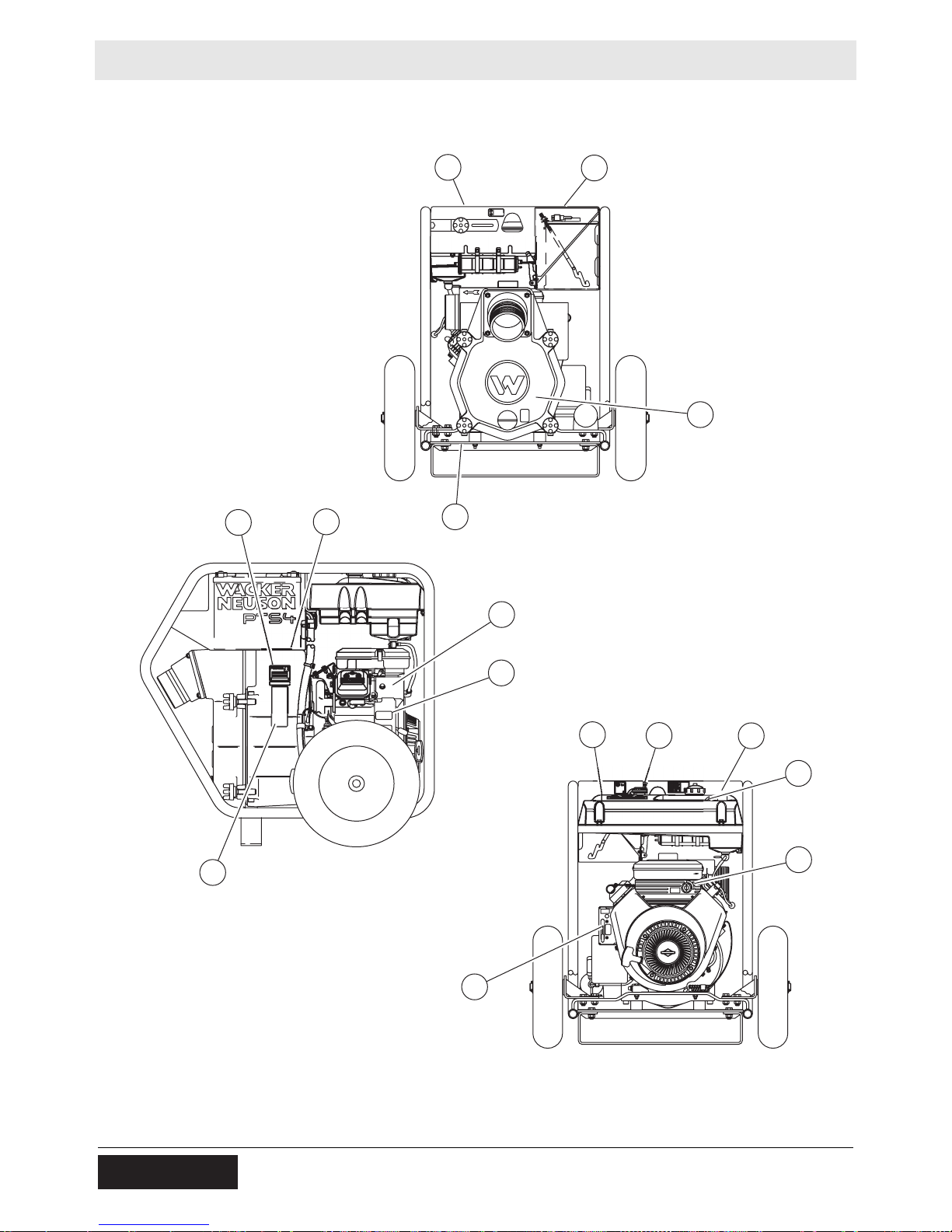
2.1 Label Locations
K
M
C
D
D
O
C
E
B
N
A
H
J
wc_gr010881
16
wc_si000771gb.fm
Page 17

PTS 4V Labels
2.2 Label Meanings
A DANGER
Asphyxiation hazard.
Engines emit carbon monoxide.
Do not run the machine indoors or in an
enclosed area.
NEVER use inside a home or garage, EVEN IF
doors and windows are open.
Only use OUTSIDE and far away from windows,
doors, and vents.
Read the Operator’s Manual.
No sparks, flames, or burning objects near the
machine.
Stop the engine before refueling.
B WARNING
Hot surface
C CAUTION
Read and understand the supplied Operator’s
Manual before operating this machine. Failure to
do so increases the risk of injury to yourself and
others.
wc_si000771gb.fm
17
Page 18

Labels PTS 4V
178764
HINWEIS
111418
AVISO
AVIS
NOTICE
D WARNING
Do not open if pump is hot. Hot water and/or
steam inside could be pressurized.
E WARNING
Never pump volatile, flammable, or low-flash-point
fluids. These fluids could ignite or explode.
178764
F NOTICE
NOTICE
HINWEIS
AVISO
AVIS
111418
Lifting point
G Guaranteed sound power level in db(A)
H Key switch:
off
on
start
18
wc_si000771gb.fm
Page 19

PTS 4V Labels
UTILITY 159116
U.S.PAT.Nos.: 6012285, 6471476,
D416858, D454357 OTHER U.S. AND
FOREIGN PATENTS PENDING
J Throttle control lever:
Turtle = Idle or Slow
Rabbit = Full or Fast
K This machine may be covered by one or more
U.S.PAT.Nos.: 6012285, 6471476,
D416858, D454357 OTHER U.S. AND
FOREIGN PATENTS PENDING
UTILITY 159116
patents.
M WARNING
Operation of This Equipment May Create Sparks That Can Start Fires Around Dry
Vegetation. A Spark Arrestor May be Required. The Operator Should Contact Local
Fire Agencies For Laws or Regulations Relating to Fire Prevention Requirements.
WARNING
Per CAL. PRC. CODE
Operation of this equipment may create sparks
that can start fires around dry vegetation. A spark
arrester may be required. The operator should
contact local fire agencies for laws or regulations
relating to fire prevention requirements.
N Certified Performance
Contractors Pump Bureau
A Bureau of AEM
The manufacturer of this pump certifies that it was
manufactured in accordance with the standards of
the Contractors Pump Bureau.
O Emission Control Information
wc_si000771gb.fm
This equipment meets U.S. EPA EVAP standards.
Evaporative Family: CW1XNHEQCL2
Exempt from tank permeation standa rd s u nde r 40
CFR 1054.145.
19
Page 20

Lifting and Transporting PTS 4V
189
3 Lifting and Transporting
WARNING
Personal injury hazard. This pump is heavy enough to cause injury if proper lifting
techniques are not used.
f Observe the guidelines below when lifting the pump.
Lifting the
machine
Transporting the
machine
Do not attempt to lift the pump unassisted. Use appropriate lif ting equipment
such as slings, chains, hooks, ramps, or jacks.
Make sure lifting equipment is attached securely and has enough weight-
bearing capacity to lift or hold the pump safely.
Remain aware of the location of other people nearby when lifting the pump.
To lift the pump, attach a hook, harness, or cable through the lifting eye.
wc_gr010882
Observe the following guidelines when transporting the pump to and from the
job site.
Drain the fuel tank before transporting the pump.
Ensure that the pump is securely strapped down in the transport vehicle to
prevent it from sliding or tipping.
Do not refuel the pump in or on the transport vehicle. Move the pump to its
operating location and then fill the fuel tank.
20
wc_tx003329gb.fm
Page 21

PTS 4V Operation
4 Operation
4.1 Preparing the Machine for First Use
1. Make sure all loose packaging materials have been removed from the
machine.
2. Check the machine and its components for damage. If there is visible
damage, do not operate the machine! Contact your Wacker Neuson dealer
immediately for assistance.
3. Take inventory of all items included with the machine and verify that all loose
components and fasteners are accounted for.
4. Attach component parts not already attached.
5. Add fluids as needed and applicable, including fuel, engine oil, and battery
acid.
6. Move the machine to its operating location.
NOTICE: There is no oil in the engine! To avoid permanently damaging the
engine, oil must be added before operating the machine for the first time. See
Technical Data for quantity and type.
4.2 Recommended Fuel
The engine requires regular grade unleaded gasoline. Use only fresh, clean
gasoline. Gasoline containing water or dirt will damage the fuel system. Consult
the engine owner’s manual for complete fuel specifications.
Use of
oxygenated
fuels
Some conventional gasolines are blended with alcohol. These gasolines are
collectively referred to as oxygenated fuels. If you use an oxygenated fuel, be
sure it is unleaded and meets the minimum octane rating requirement.
Before using an oxygenated fuel, confirm the fuel’s contents. Some states and
provinces require this information to be posted on the fuel pump.
The following is the Wacker Neuson approved percentage of oxygenates:
ETHANOL - (ethyl or grain alcohol) 10% by volume. You may use gasoline
containing up to 10% ethanol by volume (commonly referred to as E10).
Gasoline containing more than 10% ethanol (such as E15, E20, or E85) may
not be used because it could damage the engine.
If you notice any undesirable operating symptoms, try another service station,
or switch to another brand of gasoline.
Fuel system damage or performance problems resulting from the use of an
oxygenated fuel containing more than the percentages of oxygenates
mentioned above are not covered under warranty.
wc_tx003330gb.fm
21
Page 22

Operation PTS 4V
4.3 Before Starting
1. Read safety instructions at the beginning of this Operator’s Manual.
2. Place pump as near to water as possible, on a firm, flat, level surface.
3. To prime pump, remove prime plug (a) and fill pump housing with water. If the
pump housing is not filled with water before starting, it will not begin pumping.
Do not open priming plug, discharge plug, or loosen hose fittings if pump is hot!
Water or vapor inside pump may be under pressure.
WARNING
4. Check for leaks between pump and engine. If water is leaking, the seal inside
pump is worn or damaged. Continued operation may cause water damage to
engine.
5. Check that hoses are securely attached to pump. Suction hose (b) must not
have any air leaks. Tighten hose clamps (c) and couplings (d). Check that
discharge hose (e) is not restricted. Lay hose out as straight as possible.
Remove any twists or sharp bends from hose which may block the flow o f water.
6. Make sure suction strainer (f) is clean and securely attached to end of hose.
The strainer is designed to protect the pump by preventing large objects from
being pulled into the pump.
NOTICE: Strainer should be positioned so it will remain completely under water.
Running the pump with the strainer above water for long periods can damage the
pump.
7. Check fuel level, engine oil level, and condition of air cleaner.
22
wc_tx003330gb.fm
Page 23

PTS 4V Operation
a
c
d
c
e
b
f
c
wc_gr008086
wc_tx003330gb.fm
23
Page 24

Operation PTS 4V
4.4 Starting
Follow the instructions below and read starting and stopping instuctions found in
the engine owner’s manual.
1. Open the fuel valve (b1).
2. If the engine is cold, pull out th e choke control (a1). If the engine is hot, push in
the choke control (a2).
3. Move the throttle control to the fast position (c1).
4. Turn the key switch to the start position (d3) and hold it until the engine starts.
NOTICE: Do not crank engine longer than 15 seconds at a time. Extended
cranking can damage the starter motor.
5. To start the engine using manual start:
Turn the key switch to the run position (d2).
Rapidly pull the starter rope (e) to start the engine.
Leave key in run position (d2) while engine is running.
Note: The engine is equipped with a low oil protection system, which does not
allow the engine to start if the oil level is low. This device will not protect the engine
if a low oil level occurs while running. The switch opens on a pressure rise of 4 psi
±1.5 psi.
6. Push the choke in as the engine warms (a2).
7. Keep the engine throttle in the fast position while operating pump.
4.5 Stopping
1. Reduce engine RPM by moving the throttle completely to the idle position (c2).
2. Turn the engine switch to the stop position (d1).
3. Close the fuel valve (b2).
24
wc_tx003330gb.fm
Page 25

PTS 4V Operation
a1
a2
b2
b1
c1
d1
d2
d3
c2
e
wc_gr010883
wc_tx003330gb.fm
25
Page 26

Operation PTS 4V
4.6 Operation
Pump should begin pumping water within a minute depending on length of suction
hose and height of pump above water. Longer hoses will require more time.
If pump does not prime, check for loose fittings or air leak in suction hose. Make
sure strainer in water is not blocked.
Run engine at full speed while operating pump.
Do not pump corrosive chemicals or water containing toxic substances. These
fluids could create serious health and environmental hazards. Contact local
authorities for assistance.
WARNING
4.7 Pump Wrench
The wrench (a) supplied with the pump can be used to loosen and tighten: hose
couplings, knobs on pump cover, priming plug, and drain plug on front cover.
Store wrench on pump frame.
a
4.8 Accessories
Wacker Neuson offers a complete line of fittings, hoses, and clamps to properly
connect the pump to match various job conditions.
26
wc_tx003330gb.fm
Page 27

PTS 4V Operation
4.9 Hoses and Clamps
Suction hoses (a) must be rigid enough not to collapse when pump is operating.
Discharge hoses (b) are usually thin-walled collapsible hoses. Rigid hoses similar
to those used as suction hoses may also be used as discharge hoses.
Note: Suction and discharge hoses are available from Wacker Neuson. Contact
your nearest dealer for more information.
Two clamps (c) are recommended for connection of suction hoses to inlet coupling.
Note: This connection is important. Even a small air leak on the suction side of
pump will prevent the pump from priming.
For other hose connections, one T-bolt or worm-gear-type clamp is usually
sufficient to hold hoses in place. In some cases, slight variances in hose diameters
may make it necessary to add more clamps in order to maintain tight connections.
c
b
4.10 Emergency Shutdown Procedure
If a breakdown/accident occurs while the machine is operating, follow the
procedure below.
1. Stop the engine.
2. Turn off the fuel supply.
3. Remove the obstruction.
4. Unkink the hoses.
5. Allow the machine to cool.
a
wc_gr008089
6. Contact the rental yard or machine owner.
wc_tx003330gb.fm
27
Page 28

Maintenance PTS 4V
5 Maintenance
5.1 Maintaining the Emission Control System
For machines sold in North America:
Normal maintenance, replacement, or repair of emission control devices and
systems may be performed by any repair establishment or individual; however,
warranty repairs must be performed by a dealer/service center authorized by
Wacker Neuson. The use of service parts that are not equivalent in performance
and durability to authorized parts may impair the effectiveness of the emission
control system and may have a bearing on the outcome of a warranty claim.
28
wc_tx003331gb.fm
Page 29

PTS 4V Maintenance
5.2 Periodic Maintenance Schedule
The table below lists basic machine and engine maintenance. Tasks designated
with check marks may be performed by the operator . Tasks designated with square
bullet points require special training and equipment.
Refer to the engine owner’s manual for additional information.
Check fuel level.
Check engine oil level.
Inspect for leaks between
pump and engine.
Inspect air filter. Clean as
needed.
Check external hardware.
Inspect shock mounts for
damage.
Change oil in pump housing.
Change engine oil and
replace filter.
Clean or replace air cleaner.
Daily
before
starting
3
3
3
3
3
After
first
5 hours
Every
50
hours
Every
100
hours
Every
250
hours or
annually
3
Every
400
hours or
annually
Replace spark plug.
Check muffler and spark
arrester.
Check and adjust valve
clearances.
Replace in-line fuel filter.
Clean air cooling system.*
Clean oil cooler fins.*
wc_tx003331gb.fm
* Clean more often in dusty or dirty conditions.
29
Page 30

Maintenance PTS 4V
5.3 Engine Oil
Check engine oil level daily before starting engine. Add oil as required.
1. To check oil level, place machine on a level surface.
2. Clean area around oil fill (d) and remove dipstick (b).
3. Pour oil (a) slowly, checking oil level occasionally with dipstick.
4. Fill to full mark on dipstick (c). Do not overfill.
5. When measuring oil level, screw dipstick firmly in place until cap bottoms on
tube.
d
b
a
c
wc_gr010895
30
wc_tx003331gb.fm
Page 31

PTS 4V Maintenance
5.4 Changing the Engine Oil
Drain oil while engine is still warm.
1. Remove oil fill cap (a) and drain plug (b) to drain oil.
a
e
d
b
Note: In the interests of environmental protection, place a plastic sheet and a
container under the machine to collect any liquid which drains off. Dispose of this
liquid in accordance with environmental protection legislation.
2. Re-install drain plug and tighten.
3. Fill engine crankcase with recommended oil to the upper limit mark on the
dipstick.
4. Re-install oil fill cap and dips tick securely.
5. To replace the oil filter (c), remove the installed oil filter after oil has been
drained. Apply a thin coat of oil to the rubber gasket (d) of the replacement oil
filter. Screw the filter on until it just contacts the filter adapter (e), then turn it an
additional 1/2 to 3/4 turn. Refill with oil as described above.
c
wc_gr010896
WARNING
Most used oil contains small amounts of materials that can cause cancer and other
health problems if inhaled, ingested, or left in contact with skin for prolonged
periods of time.
f Take steps to avoid inhaling or ingesting used engine oil.
f Wash skin thoroughly after exposure to used engine oil.
wc_tx003331gb.fm
31
Page 32

Maintenance PTS 4V
5.5 Servicing the Air Cleaner
Service air cleaner frequently to prevent carburetor malfunction.
NOTICE: Do not run the engine without the air cle aner. Severe engine damage will
occur.
Do not use gasoline or other types of low flash point solvents for cleaning the air
cleaner. A fire or explosion could result.
The engine is equipped with a dual element air cleaner. To service air cleaner:
1. Remove cover (a), knob (b), and retaining plate (c).
2. Remove foam precleaner (d) from filter cartridge (e).
3. Wash precleaner in liquid detergent and water. Squeeze dry in a clean cloth.
Saturate precleaner in engine oil, squeeze out excess oil. Replace precleaner if
it is damaged or heavily soiled.
4. To clean cartridge, remove and tap lightly on a flat surfa ce. Replace cartridge if it
is damaged or heavily soiled.
Note: To avoid damage to precleaner or cartridge when cleaning them, do not use
petroleum solvents or pressurized air.
a
b
c
d
e
wc_gr010897
32
wc_tx003331gb.fm
Page 33

PTS 4V Maintenance
5.6 Cleaning and Checking the Spark Plug
When
Procedure
Clean or replace the spark plug as needed to ensure proper operation. Refer to
your engine owner’s manual.
WARNING
Burn hazard. The engine and muffler become very hot during operation an d require
cool-down time after the engine is stopped.
f Do not touch the engine, muffler, or spark plug until the machine is cool.
Note: Refer to section “Technical Data” for the recommended spark plug type and
the electrode gap setting.
Perform the procedure below to clean and check the spark plug.
1. Remove the spark plug and inspect it.
2. Replace the spark plug if the insulator is cracked or chipped.
3. Clean the spark plug electrodes with a wire brush.
4. Set the electrode gap (a).
5. Tighten the spark plug securely.
NOTICE: A loose spark plug can become very hot and may cause engine damage.
wc_tx003331gb.fm
wc_gr010898
33
Page 34

Maintenance PTS 4V
5.7 Cleaning the Muffler and Deflector
Overview
Requirements
Cleaning the
muffler
The muffler and deflector must be cleaned regularly to prevent combustible debris
such as leaves, grass, or twigs from igniting.
Engine is stopped.
Engine is cool to the touch.
Follow the procedure below to clean the muffler (a) and deflector (b).
b
1. Remove accumulated debris from the muffler and deflector.
2. Inspect the muffler and deflector for cracks, corrosion, or other damage.
a
wc_gr010899
3. Replace damaged parts as needed.
NOTICE: If it is necessary to remove and re-inst all the deflector during the cleaning
process, make sure to orient the opening as shown in the illustration.
5.8 Maintaining the Fuel Filter
1. Change in-line fuel filter (a) once a year.
2. Check fuel lines and fittings frequently for cracks or leaks. Replace as needed.
Note: Allow the engine to cool, and close the fuel valve before replacing the fuel
filter.
a
wc_gr010900
wc_tx003331gb.fm
34
Page 35

PTS 4V Maintenance
5.9 Adjusting the Carburetor
NOTICE: The carburetor has been factory-set to operate efficiently under most
conditions. To avoid permanently damaging the engine, do not make any
adjustments to the carburetor.
Contact your Wacker Neuson dealer for assistance if the carburetor does not
appear to be adjusted properly.
5.10 Changing Mechanical Seal Coolant
Change mechanical seal coolant every 50 hours using SAE 30W oil.
1. Remove plugs (a) from both sides of pump housing for venting.
2. Remove bottom plug (b) and allow oil to drain from oil cavity.
3. Install bottom drain plug.
4. Fill oil cavity through one of the side plug (a) holes until oil is level with top of
hole or flows out hole on opposite side.
Oil quantity - approximately 150 ml (5 ounces).
5. Install all plugs before operating pump.
a
b
wc_gr010901
wc_tx003331gb.fm
35
Page 36

Maintenance PTS 4V
5.11 Adjusting the Impeller Clearance
If it is necessary to replace impeller or volute insert, be sure clearance between
impeller and insert is adjusted correctly.
The impeller (e) should be as close to the insert (a) as possible without rubbing
against it. Clearance is adjusted by adding or removing shims (b) from behind
insert. Inserts are attached to the pump cover and must be unbolted (c) before they
can be removed.
Check clearance (d) between impeller and insert by slowly pulling starter rope to
turn impeller.
Note: Remove spark plug to make it easier to turn impeller. On diesel engines,
open decompression device before cranking engine.
If starter or crank is difficult to turn, or rubbing is heard from inside pump, the
impeller and insert are too close to each other. Remove a shim from behind insert
and check again for rubbing. Continue removing shims until impeller turns easily.
Note: It is important not to remove too many shims or the clearance between the
impeller and insert will become too wide and pump performance will be reduced.
As the impeller wears down, additional shims may be required to maintain the
clearance between the impeller and insert.
c
b
a
d
e
wc_gr010902
36
wc_tx003331gb.fm
Page 37

PTS 4V Maintenance
5.12 Cleaning the Pump
After pumping water containing a large amount of dirt or debris, clean out inside of
pump housing.
1. Remove drain plug (a) from pump housing and drain any water left in pump.
2. Loosen the four knobs (b) holding the pump cover and remove cover.
3. Clean out dirt and debris. Inspect impeller and volute insert for wear.
Note: Tighten cover evenly at all four corners using a wrench.
The impeller may develop sharp edges. Use ca re when cleaning around impeller to
prevent getting cut.
CAUTION
a
b
wc_gr010903
wc_tx003331gb.fm
37
Page 38

Maintenance PTS 4V
5.13 Long-Term Storage
If pump is being stored for more than 30 days:
Do not open priming plug, discharge plug, or cover when pump is hot.
WARNING
1. After pump has cooled, remove discharge plug from pump housing and drain
out any water left in the housing.
2. Remove pump cover and clean inside of pump housing. Coat inside of pump
with a light film of oil to reduce corrosion. A spray can of oil works well for this.
3. Tape up suction and discharge ports to prevent anything from falling into pump.
4. Change engine oil and follow procedures describ ed in engine manual for engine
storage.
5. Cover pump and engine and store in a clean, dry area.
38
wc_tx003331gb.fm
Page 39

PTS 4V Troubleshooting
6 Troubleshooting
Problem / Symptom Reason / Remedy
Pump does not take in
water.
Pump takes in water; little or
no discharge.
Suction hose leaks at inlet.
Not enough priming water in housing.
Engine speed too low. Adjust speed.
Strainer plugged. Clean strainer.
Suction hose damaged. Replace or repair suction
hose.
Air leak at suction port. Check that fittings are tight and
sealing properly.
Pump too high above water.
Debris collecting in pump housing. Clean pump
housing.
Too much clearance between impeller and insert.
Engine speed too low. Adjust engine speed.
Suction strainer partially plugged. Clean suction
strainer.
Impeller worn. Adjust clearance by adding shims or
replace impeller.
Volute insert worn or damaged. Adjust clearance or
replace volute insert.
Clamps are not sealing properly. Tighten, replace, or
add clamps.
Suction hose diameter is too large.
Suction hose is damaged.
Discharge hose does not
stay on coupling.
Impeller does not turn;
pump is hard to start.
Engine does not start or
stops during operation.
Pressure may be too high for clamps being used. Add
another clamp.
Discharge hose kinked or end blocked. Check
discharge hose.
Impeller jammed or blocked. Open pump cover and
clean dirt and debris from inside of pump housing.
Impeller and insert binding. Adjust clearance by
removing shim from behind insert.
Debris in pump housing, blocking impeller.
Low oil level in engine.
Impeller rubbing on insert.
wc_tx003332gb.fm
39
Page 40

Technical Data PTS 4V
7 Technical Data
7.1 Engine
Engine power rating
Gross power rating per SAE J1995. Actual power output may vary due to
conditions of specific use.
Machine PTS 4V
Engine
Engine make Briggs and Stratton
Engine model Vanguard 305447
Max. rated power @ rated
speed
Spark plug Champion RC12YC
Electrode gap mm (in.) 0.76 (0.030)
Operating speed rpm 3600 ± 100
Air cleaner type Dual element
Battery V/ccA/
Engine lubrication oil grade /
Engine oil capacity L (qt) 1.6 (1.7)
Fuel type Regular unleaded gasoline
Fuel tank capacity L (gal) 17.4 (4.6)
Running time hr 3.6
kW (hp) 11.9 (16) @ 3600 rpm
12 / 230 / 32 / 22NF
Ah/size
>5°C (40°F) SAE 5W30 / SJ or higher
service
class
<5°C (40°F) SAE 10W30 / SJ or higher
40
wc_td000560gb.fm
Page 41

PTS 4V Technical Data
7.2 Pump
Machine PTS 4V
Pump
Operating weight kg (lb) 162 (358)
Max. suction lift * m (ft) 7.62 (25)
Max. discharge head m (ft) 32 (106)
Mechanical seal lubrication oil grade
Suction / discharge diameter mm (in.) 100 (4)
Max. solid size diameter mm (in.) 50 (2)
Max. flow rate ** m
*Based on pump operating at sea level. Maximum suction lift will be less at higher altitudes.
**Zero net head
7.3 Sound Measurements
Products are tested for sound pressure level in accordance with EN ISO
11201:2010.
Sound power level is tested in accordance with European Directive 2000/14/EC Noise Emission in the Environment by Equipment for use outdoors.
Machine
PTS4V 91 104
Sound Pressure at Operator’s
ml (oz.)
(gpm)
Location dB(A)
SAE 30
150 (5)
3
/hr
Guaranteed Sound Power
156 (689)
dB(A)
wc_td000560gb.fm
41
Page 42

Technical Data PTS 4V
111891
117554
7.4 Dimensions
mm (in.)
890 (35)
117554
915 (36)
111891
890
(35)
wc_gr008090
wc_td000560gb.fm
42
Page 43

Emission Control Systems Information and Warranty—
8 Emission Control Systems Information and Warranty—Gasoline
The Emission Control Warranty and associated information is valid only for the
U.S.A., its territories, and Canada.
8.1 Emission Control System Background Information
Introduction
Wacker Neuson spark-ignited engines/equipment must conform with applicable
Environmental Protection Agency (EPA) and the State of California emissions
regulations. There are two types of emissions that fall under these regulations: 1)
exhaust, and 2) evaporative. These regulations require that manufacturers warrant
the emission control systems for defects in materials and workmanship.
Furthermore, EPA and California regulations require all manufacturers to furnish
written instructions describing how to operate and maintain the e ngines/equipment
including the emission control systems. This information is provided with all
Wacker Neuson engines/equipment at the time of purchase.
Exhaust Emissions
The combustion process produces carbon monoxide, oxides of nitrogen, and
hydrocarbons. Control of hydrocarbons and oxides of nitrogen is very important
because, under certain conditions, they react to form photochemical smog when
subjected to sunlight. Carbon monoxide does not react in the same way, but it is
toxic.
Wacker Neuson utilizes lean carburetor settings and other systems to reduce the
emissions of carbon monoxide, oxides of nitrogen, and hydrocarbons.
Evaporative Emissions
Evaporative emissions are fuel emissions and generally include emissions that
result from permeation of fuel through the fuel-system materials or from ventilation
of the fuel system.
Wacker Neuson utilizes low-permeation fuel lines and fuel tanks where applicable
to reduce evaporative emissions.
Problems that may affect Emissions
If any of the following symptoms arise, have the engine/equipment inspected and
repaired by a Wacker Neuson dealer/service center.
Hard starting or stalling after starting
Rough idling
Misfiring or backfiring under load
Afterburning (backfiring)
Presence of black exhaust smoke during operation
High fuel consumption
wc_tx001754gb.fm 43
Page 44

Emission Control Systems Information and Warranty—Gasoline
Tampering and Altering
Tampering with or altering the emission control system may increase emissions
beyond the legal limit. If evidence of tamp ering is found, Wacker Neuson may deny
a warranty claim. Among those acts that constitute tampering are:
Removing or altering of any part of the air intake, fuel, or exhaust systems.
Altering or defeating the speed-adjusting mechanism causing the engine to
operate outside its design parameters.
8.2 Limited Defect Warranty for Exhaust Emission Control System
See the supplied engine owner’s manual for the applicable emission warranty
statement.
8.3 Limited Defect Warranty for Wacker Neuson Evaporative
Emission Control Systems
The Emission Control Warranty is valid only for the U.S.A., its territories, and
Canada.
Wacker Neuson Sales Americas, LLC, N92 W15000 Anthony Avenue,
Menomonee Falls, WI 53051, (hereinafter “Wacker Neuson”) warrants to the initial
retail purchaser and each subsequent owner, that this engine/equipment, including
all parts of its evaporative emission cont rol system, have bee n designed, built, and
equipped to conform at the time of initial sale to all applicable evaporative emission
regulations of the U.S. Environmental Protection Agency (EPA), and that the
engine/equipment is free of defects in materials and workmanship which would
cause this engine/equipment to fail to conform to EPA regulations during its
warranty period.
Wacker Neuson is also liable for damages to other engine/equipment components
caused by a failure of any warranted parts during the warranty period.
Limited Defect Warranty Period for Wacker Neuson Evaporative
Emission Control Systems
The warranty period for this engine/equipment begins on the date of sale to the
initial purchaser and continues for a minimum of two (2) years. For the warranty
terms for your specific engine/equipment, visit wackerneuson.com.
Any implied warranties are limited to the duration of this written warranty.
What is covered
Wacker Neuson recommends the use of genuine Wacker Neuson parts, or the
equivalent, whenever maintenance is performed. The use of replacement parts not
equivalent to the original parts may impair the effectiveness of the engine/
equipment emission controls systems. If such a replacement part is used in the
repair or maintenance of the engine/equipment, assure yourself that such part is
warranted by its manufacturer to be equivalent to the parts offered by Wacker
Neuson in performance and durability. Furthermore, if such a replacement part is
used in the repair or maintenance of the engine/equipment, and an authorized
44 wc_tx001754gb.fm
Page 45

Emission Control Systems Information and Warranty—
Wacker Neuson dealer/service center determines it is defective or causes a failure
of a warranted part, the claim for repair of the engine/equipment may be denied. If
the part in question is not related to the reason the engine/equipment requires
repair, the claim will not be denied.
For the components listed in the following table, an authorized Wacker Neuson
dealer/service center will, at no cost to you, make the necessary diagnosis, repair,
or replacement necessary to ensure that the engine/equipment complies with the
applicable EPA regulations. All defective parts replaced under this warranty
become property of Wacker Neuson.
System Covered Components
Evaporative emissions Fuel tank (if applicable)
Fuel tank cap (if applicable)
Fuel line (if applicable)
Fuel line fittings (if applicable)
Clamps (if applicable)
Carbon canister (if applicable)
Purge port connector (if applicable)
Miscellaneous parts associated with the
evaporative emission control system
Clamps
Gaskets
Mounting brackets
What is not covered
Failures other than those resulting from defects in material or workmanship.
Any systems or parts which are affected or damaged by owner abuse,
tampering, neglect, improper maintenance, misuse, improper fueling,
improper storage, accident and/or collision; the incorporation of, or any use
of, add-on or modified parts, or unsuitable attachments, or the alteration of
any part.
Replacement of expendable maintenance items made in connection with
required maintenance services after the item’s first scheduled replacement
as listed in the maintenance section of the engine/equipment operator’s
manual, such as spark plugs and filters.
Incidental or consequential damages such as loss of time or the use of the
engine/equipment, or any commercial loss due to the failure of the engine/
equipment.
Diagnosis and inspection charges that do not result in warranty-eligible
service being performed.
Any non-authorized replacement part, or malfunction of authorized p arts due
to use of-non authorized parts.
Owner’s Warranty Responsibility
The engine/equipment owner, is responsible for the performance of the required
maintenance listed in the Wacker Neuson engine/equipment operator’s manual.
Wacker Neuson recommends that all receipts covering maintenance on the
wc_tx001754gb.fm 45
Page 46

Emission Control Systems Information and Warranty—Gasoline
engine/equipment be retained, but Wacker Neuson cannot deny warranty
coverage solely for the lack of receipts or for the failure to ensure the performance
of all scheduled maintenance.
Normal maintenance, replacement, or repair of emission control devices and
systems may be performed by any repair establishment or individual; however,
warranty repairs must be performed by an authorized Wacker Neuson dealer/
service center.
The engine/equipment must be presented to an authorized W acker Neuson dealer/
service center as soon as a problem exists. Contact Wacker Neuson Product
Support Department (1-800-770-0957) or visit wackerneuson.com to find a dealer/
service center in your area, or to answer questions regarding warranty rights and
responsibilities.
How to Make a Claim
In the event that any emission-related part is found to be defective during the
warranty period, you shall notify Wacker Neuson Product Support Department
(1-800-770-0957, or technical.support@wackerneuson.com, or
wackerneuson.com), and you will be advised of the appropriate dealer/service
center where warranty repair can be performed. All repairs qualifying under this
limited warranty must be performed by an authorized Wacker Neuson dealer/
service center.
You must take your Wacker Neuson engine/equipment along with proof of original
purchase date, at your expense, to the authorized Wacker Neuson dealer/service
center during their normal business hours.
For owners located more than 100 miles from an authorized dealer/service center
(excluding the states with high-altitude areas as identified in 40 CFR Part 1068,
Appendix III), Wacker Neuson will p ay for pre-a pproved shipping cost s to and fro m
an authorized Wacker Neuson dealer/service center.
Claims for repair or adjustment found to be caused solely by defects in material or
workmanship will not be denied because the engine/equipment was not properly
maintained and used.
The warranty repairs should be completed in a reasonable amount of time, not to
exceed 30 days.
46 wc_tx001754gb.fm
Page 47

Page 48

Page 49

Page 50

Page 51

Page 52

Page 53

Page 54

Page 55

Page 56

Page 57

Page 58

Page 59

Page 60

Wacker Neuson SE · Preußenstraße 41 · D-80809 München · Tel.: +49-(0)89-3 54 02-0 · Fax: +49 - (0)89-3 54 02-390
Wacker Neuson Corporation · N92W15000 Anthony Ave. · Menomonee Falls, WI 53051 · Tel. : (262) 255-0500 · Fax: (262) 255-0550 ·Tel. : (800) 770-0957
Wacker Neuson Limited - Room 1701–03 & 1717–20, 17/F. Tower 1, Grand Century Place, 193 Prince Edward Road West, Mongkok, Kowloon, Hongkong.
Tel: (852) 3605 5360, Fax: (852) 2758 0032
 Loading...