

Page 1
Operator’s Manual
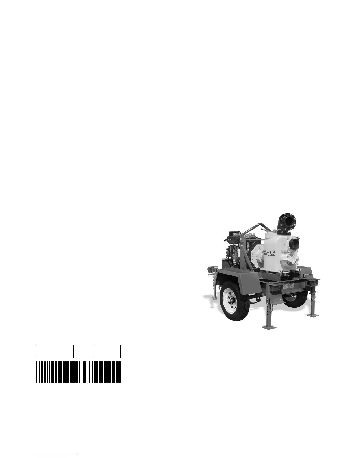
Pump
PT 6L
0154629en 008 0810
0154629EN
Page 2

Copyright
notice
© Copyright 2010 by Wacker Neuson Corporation.
All rights, including copying and distribution rights, are reserved.
This publication may be photocopied by the original purchaser of the machine. Any
other type of reproduction is prohibited without express written permission from
Wacker Neuson Corporation.
Any type of reproduction or distribution not authorized by Wacker Neuson Corporation
represents an infringement of valid copyrights. Violators will be prosecuted.
Trademarks
Manufacturer
All trademarks referenced in this manual are the property of their respective owners.
Wacker Neuson Corporation
N92W15000 Anthony Avenue
Menomonee Falls, WI 53051 U.S.A.
Tel: (262) 255-0500 · Fax: (262) 255-0550 · Tel: (800) 770-0957
www.wackerneuson.com
Original
instructions
This Operator’s Manual presents the original instructions. The original language of this
Operator’s Manual is American English.
Page 3

PT 6L Foreword
Foreword
Machines
covered by
this manual
Machine Item Number
PT 6LT
PT 6LS
0007175
0007174
Machine
documentation
Expectations
for
information in
this manual
Keep a copy of the Operator’s Manual with the machine at all times.
Use the separate Parts Book supplied with the machine to order replacement
parts.
Refer to the separate Repair Manual for detailed instructions on servicing and
repairing the machine.
If you are missing any of these documents, please contact Wacker Neuson
Corporation to order a replacement or visit www.wackerneuson.com.
When ordering parts or requesting service information, be prepared to provide
the machine model number, item number, revision number, and serial number.
This manual provides information and procedures to safely operate and
maintain the above Wacker Neuson model(s). For your own safety and to
reduce the risk of injury, carefully read, understand, and observe all instructions
described in this manual.
Wacker Neuson Corporation expressly reserves the right to make technical
modifications, even without notice, which improve the performance or safety
standards of its machines.
The information contained in this manual is based on machines manufactured
up until the time of publication. Wacker Neuson Corporation reserves the right
to change any portion of this information without notice.
CALIFORNIA
Proposition
65 Warning
Laws
pertaining to
spark
arresters
Engine exhaust, some of its constituents, and certain vehicle components, contain
or emit chemicals known to the State of California to cause cancer and birth
defects or other reproductive harm.
NOTICE: State Health Safety Codes and Public Resources Codes specify that in
certain locations spark arresters be used on internal combustion engines that use
hydrocarbon fuels. A spark arrester is a device designed to prevent accidental
discharge of sparks or flames from the engine exhaust. Spark arresters are
qualified and rated by the United States Forest Service for this purpose. In order to
comply with local laws regarding spark arresters, consult the engine distributor or
the local Health and Safety Administrator.
Manufacturer’s
approval
This manual contains references to approved parts, attachments, and
modifications. The following definitions apply:
Approved parts or attachments are those either manufactured or provided by
Wacker Neuson.
Approved modifications are those performed by an authorized Wacker
Neuson service center according to written instructions published by Wacker
Neuson.
wc_tx001594gb.fm 3
Page 4

Foreword PT 6L
Unapproved parts, attachments, and modifications are those that do not
meet the approved criteria.
Unapproved parts, attachments, or modifications may have the following
consequences:
Serious injury hazards to the operator and persons in the work area
Permanent damage to the machine which will not be covered under warranty
Contact your Wacker Neuson dealer immediately if you have questions about
approved or unapproved parts, attachments, or modifications.
4 wc_tx001594gb.fm
Page 5

Table of ContentsPT 6L
Foreword 3
1 Safety Information 9
1.1 Signal Words Used in this Manual ....................................................... 9
1.2 State Regulations Concerning Trailers ............................................... 10
1.3 Safety Guidelines for Operating the Machine ..................................... 10
1.4 Operator Safety while Using Internal Combustion Engines ............... 12
1.5 Service Safety .................................................................................... 13
1.6 Towing Safety ..................................................................................... 14
1.7 Reporting Trailer Safety Defects ........................................................ 14
2 Labels 16
2.1 Label Locations .................................................................................. 16
2.2 Label Meanings .................................................................................. 17
3 Lifting and Transporting 20
3.1 Lifting the Machine ............................................................................. 20
3.2 Tires ................................................................................................... 21
3.3 Wheels and Lug Nuts ......................................................................... 21
3.4 Tongue Jack ....................................................................................... 21
3.5 Safety Chains ..................................................................................... 22
3.6 Lights .................................................................................................. 23
4 Operation 24
4.1 Preparing the Machine for First Use ................................................... 24
4.2 Control / Component Descriptions ..................................................... 24
4.3 Control / Component Locations .......................................................... 25
4.4 Recommended Fuel ........................................................................... 26
4.5 Before Starting the Engine ................................................................. 26
4.6 Before Starting the Pump ................................................................... 26
4.7 Starting ............................................................................................... 27
4.8 Stopping ............................................................................................. 28
wc_bo0154629en_008TOC.fm 5
Page 6

Table of Contents PT 6L
4.9 Automatic Shutdown System ..............................................................29
4.10 Important Operation Note ....................................................................29
4.11 Hoses ..................................................................................................30
4.12 Hose Couplings ...................................................................................30
4.13 Hose Clamps .......................................................................................30
4.14 Strainer ................................................................................................30
4.15 Discharge Port .....................................................................................31
4.16 Covers .................................................................................................32
4.17 Towing the Machine ............................................................................34
4.18 Emergency Shutdown Procedure ........................................................35
5 Maintenance 36
5.1 Periodic Maintenance Schedule ..........................................................36
5.2 Engine Fuel Delivery System Maintenance .........................................37
5.3 Servicing the Air Cleaner .....................................................................37
5.4 Maintaining the Fuel Filter ...................................................................38
5.5 Priming the Fuel System .....................................................................38
5.6 Lubrication ...........................................................................................39
5.7 Engine Oil ............................................................................................40
5.8 Valve Clearances ................................................................................40
5.9 Fan Belt ...............................................................................................41
5.10 Pump Housing Mounting Bolts ............................................................42
5.11 Mechanical Seal Lubrication ...............................................................43
5.12 Bearing Housing Lubrication ...............................................................44
5.13 Impeller Inspection ..............................................................................44
5.14 Engine Cooling Fins ............................................................................47
5.15 Battery .................................................................................................47
5.16 Troubleshooting ...................................................................................48
5.17 Long-Term Storage .............................................................................49
6 Technical Data 50
6.1 Engine .................................................................................................50
6.2 Pump ...................................................................................................51
6.3 Lubrication ...........................................................................................51
6.4 Trailer and Skid ...................................................................................51
6.5 Dimensions ..........................................................................................52
6 wc_bo0154629en_008TOC.fm
Page 7

Table of ContentsPT 6L
7 Schematics 53
7.1 Trailer Wiring ............................................................................................... 53
7.2 Electrical Wiring (0007174 < Rev 120; 0007175 < Rev 123) ..................... 54
7.3 Electrical Wiring Components (0007174 < Rev 120; 0007175 < Rev 123) . 55
7.4 Electrical Wiring (0007174 > Rev 119; 0007175 > Rev 122) ..................... 56
7.5 Electrical Wiring Components (0007174 > Rev 119; 0007175 > Rev 122) . 57
wc_bo0154629en_008TOC.fm 7
Page 8

Table of Contents PT 6L
8 wc_bo0154629en_008TOC.fm
Page 9
PT 6L Safety Information
1 Safety Information
1.1 Signal Words Used in this Manual
This manual contains DANGER, WARNING, CAUTION, NOTICE, and
NOTE signal words which must be followed to reduce the possibility
of personal injury, damage to the equipment, or improper service.
This is the safety alert symbol. It is used to alert you to potential personal hazards.
f Obey all safety messages that follow this symbol.
DANGER
DANGER indicates a hazardous situation which, if not avoided, will result in death
or serious injury.
f To avoid death or serious injury from this type of hazard, obey all safety mes-
sages that follow this signal word.
WARNING
WARNING indicates a hazardous situation which, if not avoided, could result in
death or serious injury.
f To avoid possible death or serious injury from this type of hazard, obey all safety
messages that follow this signal word.
CAUTION
CAUTION indicates a hazardous situation which, if not avoided, could result in
minor or moderate injury.
f To avoid possible minor or moderate injury from this type of hazard, obey all
safety messages that follow this signal word.
NOTICE: Used without the safety alert symbol, NOTICE indicates a
situation which, if not avoided, could result in property damage.
Note: A Note contains additional information important to a procedure.
wc_si000524gb.fm 9
Page 10

Safety Information PT 6L
1.2 State Regulations Concerning Trailers
Trailer laws covering such things as brakes, lights, safety chains, etc.,
will vary from state to state. Make certain that your trailer is in
compliance with the regulations of the state in which the trailer will be
used. If you are not sure what these regulations are, contact the state
motor vehicle department for information.
In some states, trailers must be registered and licensed by the State
Department of Transportation. Before towing, be sure to check
licensing requirements.
1.3 Safety Guidelines for Operating the Machine
Familiarity and proper training are required for the safe operation of the
machine. Machines operated improperly or by untrained personnel
can be hazardous. Read the operating instructions contained in this
WARNING
manual and the engine manual, and familiarize yourself with the
location and proper use of all controls. Inexperienced operators should
receive instruction from someone familiar with the machine before
being allowed to operate it.
Operator qualifications
Only trained personnel are permitted to start, operate, and shut down
the machine. They also must meet the following qualifications:
• have received instruction on how to properly use the machine
• are familiar with required safety devices
The machine must not be accessed or operated by:
• children
• people impaired by alcohol or drugs
Personal Protective Equipment (PPE)
Wear the following Personal Protective Equipment (PPE) while
operating this machine:
• Close-fitting work clothes that do not hinder movement
• Safety glasses with side shields
• Hearing protection
• Safety-toed footwear
1.3.1 Do not touch the engine or muffler while the engine is on or
immediately after it has been turned off. These areas get hot and may
cause burns.
1.3.2 Do not use accessories or attachments that are not recommended by
Wacker Neuson. Damage to equipment and injury to the user may
result.
10 wc_si000524gb.fm
Page 11

PT 6L Safety Information
1.3.3 Never leave the machine running unattended.
1.3.4 Never operate this machine in applications for which it is not intended.
1.3.5 Do not open the priming plug when the pump is hot. Do not loosen or
remove inlet or discharge hose fittings when the pump is hot. Hot water
inside could be pressurized much like the radiator on an automobile.
Allow the pump to cool to the touch before loosening the plug and
before loosening or removing the inlet or discharge hose fittings.
1.3.6 NEVER position the pump on a loose, uneven, or unstable surface
where it can tip, roll, slide or fall! The pump must be secure before
operating. Position the pump on a firm, flat surface; adjust the trailer
jacks to be sure the pump is level and supported firmly.
1.3.7 NEVER open the pump housing cover while the pump is operating or
start the pump with the cover off. The rotating impeller inside the pump
can cut or sever objects caught in it.
1.3.8 NEVER block or restrict flow from the inlet line or the discharge line.
Remove kinks from the discharge line before starting the pump.
Operation with a blocked inlet line or discharge line can cause water
inside the pump to overheat.
1.3.9 NEVER reach into or insert anything into the pump while the engine is
on! The impeller inside the pump housing is turning at all times while
the engine is running.
1.3.10 DO NOT allow anyone to stand in front of the discharge port when
starting the engine or while priming the pump! The sudden out-rush of
water could push or knock a person down.
1.3.11 ALWAYS make sure the hose connections on the pump are tight. A
loose connection could cause water to spray or result in a hose falling
off the pump while it is in operation.
1.3.12 ALWAYS make sure the water stream from the pump discharge is not
directed in such a way so as to cause erosion to the surrounding
ground or damage or weakening of nearby structures!
wc_si000524gb.fm 11
Page 12
Safety Information PT 6L
1.4 Operator Safety while Using Internal Combustion Engines
WARNING
Internal combustion engines present special hazards during operation and fueling.
Failure to follow the warnings and safety standards could result in severe injury or
death.
f Read and follow the warning instructions in the engine owner’s manual and the
safety guidelines below.
DANGER
Asphyxiation hazard. Using a pump indoors CAN KILL YOU IN MINUTES. Pump
exhaust contains carbon monoxide. This is a poison you cannot see or smell.
f NEVER use this pump inside a home or garage, EVEN IF doors and windows
are open. Only use OUTSIDE and far away from windows, doors, and vents.
f NEVER use a pump inside an enclosed area, such as a tunnel or a trench,
unless adequate ventilation is provided through such items as exhaust fans or
hoses.
Operating safety
When operating the pump:
• Keep the area around exhaust pipe free of flammable materials.
• Check the fuel lines and the fuel tank for leaks and cracks before
starting the engine.
When operating the pump:
• Do not smoke while operating the machine.
• Do not run the machine if fuel leaks are present or the fuel lines
are loose.
• Do not run the engine near sparks or open flames.
• Do not touch the engine or muffler while the engine is running or
immediately after it has been turned off.
• Do not operate a machine when its fuel cap is loose or missing.
• Do not start the engine if fuel has spilled or a fuel odor is present.
Move the machine away from the spill and wipe the machine dry
before starting.
Refueling safety
When refueling the engine:
• Clean up any spilled fuel immediately.
• Refill the fuel tank in a well-ventilated area.
12 wc_si000524gb.fm
Page 13

PT 6L Safety Information
• Replace the fuel tank cap after refueling.
When refueling the engine:
• Do not smoke.
• Do not refuel a hot or running engine.
• Do not refuel the engine near sparks or open flames.
• Do not refuel if the machine is positioned in a truck fitted with a
plastic bed liner. Static electricity can ignite the fuel or fuel vapors.
1.5 Service Safety
A poorly maintained machine can become a safety hazard! In order
for the machine to operate safely and properly over a long period of
time, periodic maintenance and occasional repairs are necessary.
WARNING
Personal Protective Equipment (PPE)
Wear the following Personal Protective Equipment (PPE) while
servicing or maintaining this machine:
• Close-fitting work clothes that do not hinder movement
• Safety glasses with side shields
• Hearing protection
• Safety-toed footwear
In addition, before servicing or maintaining the machine:
• Tie back long hair.
• Remove all jewelry (including rings).
1.5.1 Do not attempt to clean or service the machine while it is running.
Rotating parts can cause severe injury.
1.5.2 Do not use gasoline or other types of fuels or flammable solvents to
clean parts, especially in enclosed areas. Fumes from fuels and
solvents can become explosive.
1.5.3 DO NOT attempt to clean or service the machine while it is running.
1.5.4 DO NOT operate the machine without an air cleaner.
When replacement parts are required for this machine, use only
Wacker Neuson replacement parts or those parts equivalent to the
original in all types of specifications, such as physical dimensions,
type, strength, and material.
1.5.5 Keep the machine clean and labels legible. Replace all missing and
hard-to-read labels. Labels provide important operating instructions
and warn of dangers and hazards.
wc_si000524gb.fm 13
Page 14

Safety Information PT 6L
1.5.6 ALWAYS replace the safety devices and guards after repairs and
maintenance.
1.5.7 ALWAYS check all external fasteners at regular intervals.
1.5.8 ALWAYS remain aware of moving parts and keep hands, feet, and
loose clothing away from the moving parts of the machine.
1.6 Towing Safety
Towing a large trailer requires special care. Both the trailer and vehicle
must be in good condition and securely fastened to each other to
reduce the possibility of an accident.
WARNING
1.6.1 ALWAYS check that the hitch and coupling on the vehicle are rated
equal to, or greater than, the trailer’s “gross vehicle weight rating”
(GVWR).
1.6.2 ALWAYS inspect the hitch and coupling for wear or damage. DO NOT
tow the trailer using defective parts.
1.6.3 ALWAYS make sure the coupling is securely fastened to the vehicle.
1.6.4 ALWAYS check the tires on the trailer for tread wear, inflation, and
condition. Replace worn tires.
1.6.5 ALWAYS connect the safety chains.
1.6.6 ALWAYS connect the breakaway cable safety hook to the bumper or
rear of the vehicle. DO NOT attach it to the hitch.
1.6.7 ALWAYS test the surge brakes on the trailer and the brakes on the
vehicle that will be used for towing.
1.6.8 ALWAYS make sure directional and trailer lights are connected and
working properly.
1.6.9 ALWAYS check that the lug nuts holding the wheels are tight and that
none are missing.
1.7 Reporting Trailer Safety Defects
If you believe your trailer has a defect which could cause a crash or
could cause injury or death, you should immediately inform the
National Highway Traffic Safety Administration (NHTSA) in addition to
notifying Wacker Neuson Corporation.
14 wc_si000524gb.fm
Page 15

PT 6L Safety Information
If NHTSA receives similar complaints, it may open an investigation;
and if it finds that a safety defect exists in a group of vehicles, it may
order a recall and remedy campaign. However, NHTSA cannot
become involved in individual problems between you, your dealer, or
Wacker Neuson Corporation.
To contact NHTSA, you may either contact the Auto Safety Hotline tollfree at 1-800-424-9393 (or 366-0129 in Washington DC area),
www.nhtsa.com, or write to NHTSA, U.S. Department of
Transportation, 400 7th Street SW, (NSA-11), Washington, DC 20590.
You can also obtain other information about motor vehicle safety from
the Auto Safety Hotline.
wc_si000524gb.fm 15
Page 16
Labels PT 6L
2Labels
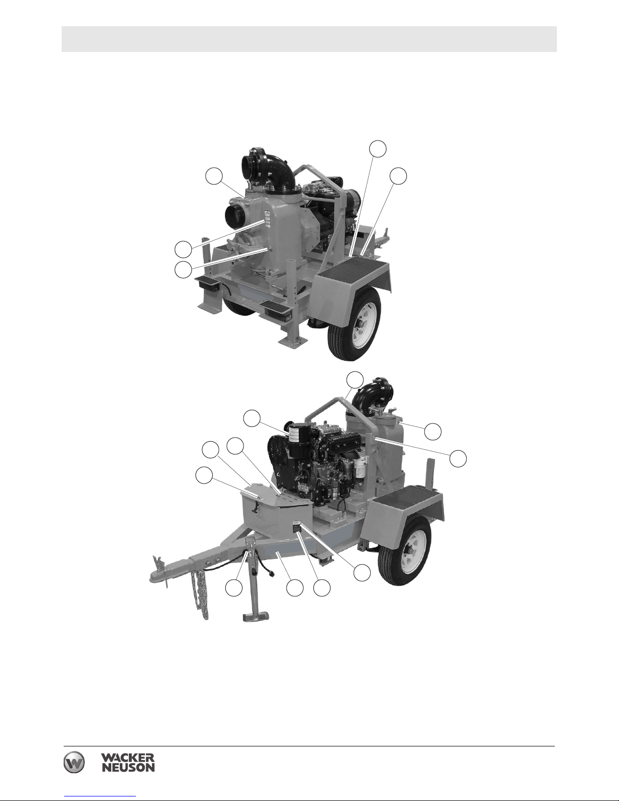
2.1 Label Locations
13
3
7
6
4
11
12
2
3
1
6
5
9
814 10
wc_gr001145
16 wc_si000523gb.fm
Page 17
PT 6L Labels
2.2 Label Meanings
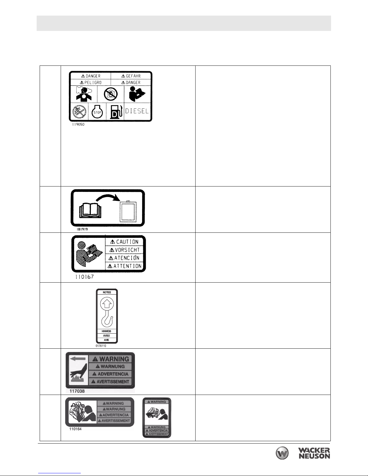
DANGER!
Asphyxiation hazard.
Engines emit carbon monoxide.
Do not run the machine indoors or in an
enclosed area.
NEVER use inside a home or garage, EVEN
IF doors and windows are open.
1
2
Only use OUTSIDE and far away from win-
dows, doors, and vents.
Read the Operator’s Manual.
No sparks, flames, or burning objects near
the machine.
Stop the engine before refueling.
CAUTION!
Use only clean, filtered diesel fuel.
Storage location of Operator’s Manual. The
Operator’s Manual should be stored on the
machine.
CAUTION!
Read and understand the supplied Operator’s
Manual before operating this machine. Failure to
3
do so increases the risk of injury to yourself and
others.
NOTICE
Lifting point.
4
WARNING!
Hot surface!
5
WARNING!
Pressurized contents. Do not open when hot!
6
wc_si000523gb.fm 17
Page 18
Labels PT 6L
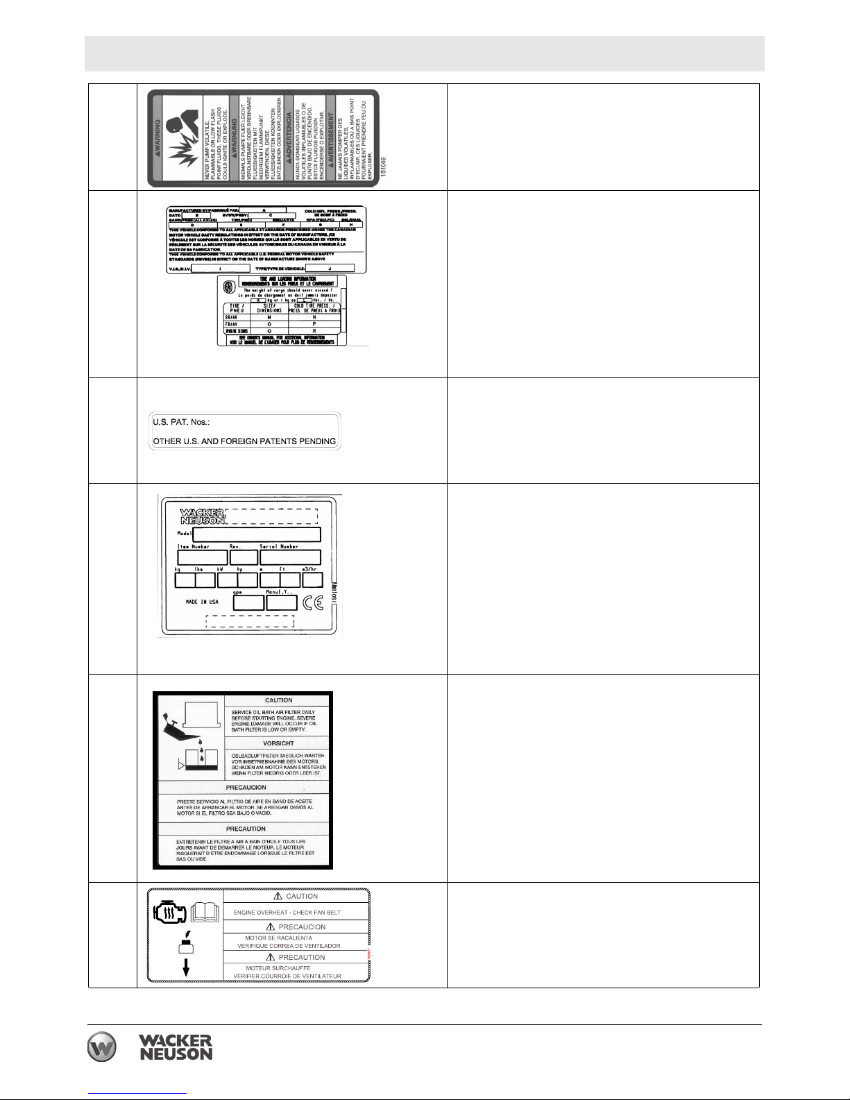
WARNING!
Never pump volatile, flammable, or low-flash-
7
8
9
point fluids. These fluids could ignite or
explode.
Tire Information
Certification Label (VIN Number)
Also attached to each unit is a Certification
Label. This label specifies that the trailer conforms with all Federal Motor Vehicle Standards
in effect at the time of manufacture. The label
includes the Vehicle Identification Number (VIN)
for the trailer.
This machine may be covered by one or more
patents.
10
11
A nameplate listing the model number, item
number, revision number, and serial number is
attached to each unit. Please record the information found on this nameplate so it will be
available should the nameplate become lost or
damaged. When ordering parts or requesting
service information, you will always be asked to
specify the model number, item number, revision
number, and serial number of the unit.
CAUTION!
Service oil bath air filter daily before starting
engine. Severe engine damage will occur if oil
bath filter is low or empty.
CAUTION!
Engine overheat - Check fan belt.
12
18 wc_si000523gb.fm
Page 19
PT 6L Labels
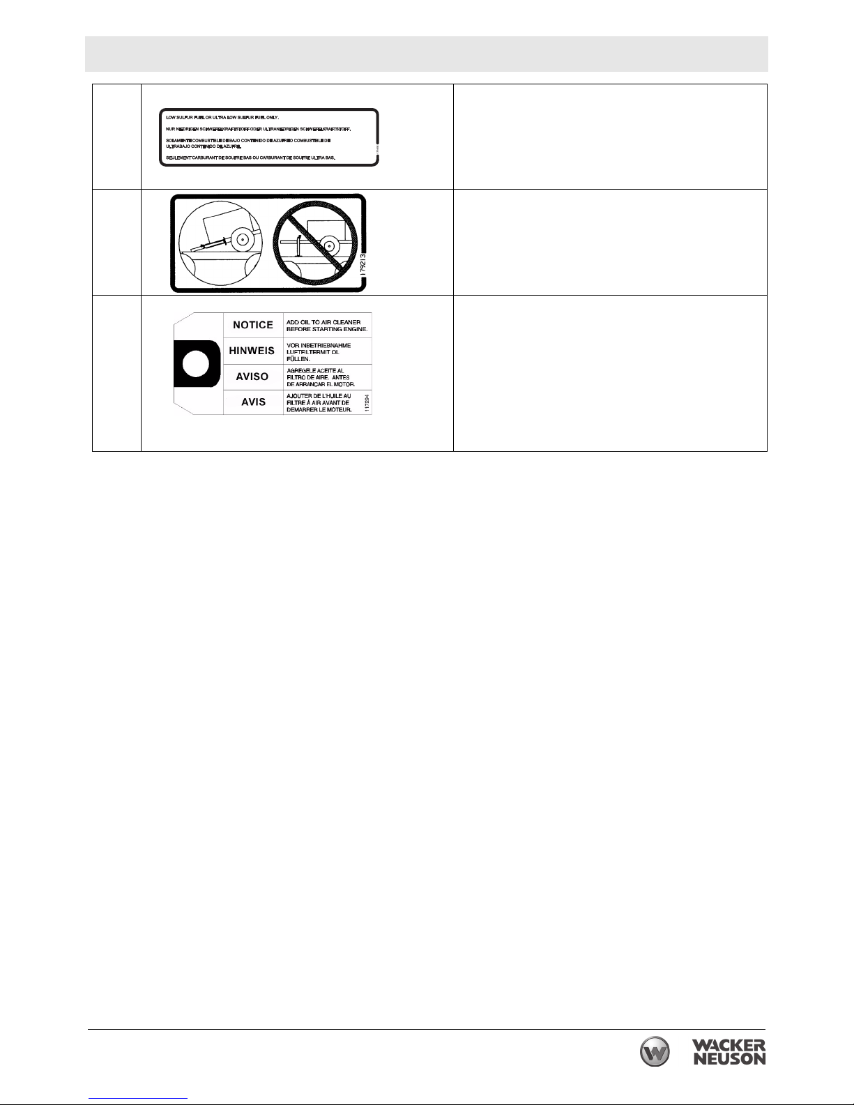
Low sulfur fuel or ultra low sulfur fuel only.
13
Transport position of the jack
14
NOTICE
Add oil to air cleaner before starting engine.
15
wc_si000523gb.fm 19
Page 20

Lifting and Transporting PT 6L
3 Lifting and Transporting
3.1 Lifting the Machine
See Graphic: wc_gr003180
Attach a sling or chain to the lifting eye (a) using a suitable hook or
shackle. Each lifting device must have capacity of at least 1090 Kg
(2400 lbs.).
Only use steel ropes or chains for hoisting. The rope or chain must
have the suitable specified lifting capacity of 1090 Kg (2400 lbs.). Do
WARNING
CAUTION
WARNING
not use improvised ropes or chains.
Never use any other part of the PT6 Pump to lift the machine, as
severe damage may occur.
Do not stand under or get onto the machine while it is being hoisted or
moved.
a
wc_gr003180
20 wc_tx001595gb.fm
Page 21
PT 6L Lifting and Transporting
3.2 Tires
Keep the tires properly inflated and make sure they have the proper
WARNING
3.3 Wheels and Lug Nuts
load rating. Under-inflated tires may cause a blowout which could
result in fishtailing or loss of control of the towing vehicle.
Always maintain full air pressure as indicated by the tire manufacturer
on the tire's sidewalls. Check air pressure when the tires are cold,
before you move the trailer. When the trailer tires become worn or
damaged, replace them promptly with the same type, size, and load
capacity as the original tires.
For convenience and safety, it is recommended that you carry a spare
wheel and tire.
Loose or missing lug nuts can cause you to lose a wheel! Keep all lug
nuts tight.
WARNING
Before each trip, check for loose or missing lug nuts. When replacing
lug nuts, make sure the replacement nut matches the original nut
exactly. While the threads of the nut may match, the nut may be a size
that does not hold the wheel securely against the hub even when fully
tightened. Torque nuts evenly in increments to 115 Nm (85 ft.lbs.).
Note: During normal use, the lug nuts will seat during the first one
hundred miles resulting in a drop in torque. Each nut should be
checked at that time and torqued to the proper value.
3.4 Tongue Jack
See Graphic: wc_gr003181
All trailers are equipped with a tongue jack (d). Use the tongue jack to
lift and lower the trailer coupling on or off the tow vehicle hitch.
wc_tx001595gb.fm 21
Page 22
Lifting and Transporting PT 6L
3.5 Safety Chains
See Graphic: wc_gr003181
Failure to properly attach the safety chains between your trailer and
the tow vehicle can result in a runaway trailer; should the coupler and
hitch separate while towing.
WARNING
Safety chains (c) on your trailer provide added protection that it will not
become separated from the towing vehicle. Make sure the chains are
correctly attached between the towing vehicle and the trailer before
each trip.
Chains should be attached in a crossing pattern under the trailer
tongue. The chains will prevent the trailer tongue from dropping to the
ground if the trailer separates from the hitch. Rig the chains as tight as
possible with just enough slack to permit tight turns.
If a chain must be replaced, do not substitute a lighter weight chain.
This trailer must be equipped with two chains, each with a minimum
breaking strength of no less than the Gross Vehicle Weight Rating
(GVWR) of the trailer. All chain attachments, including hooks, must be
at least as strong as the chain. Replace damaged chains. DO NOT
weld or attempt to repair damaged chains.
c
d
wc_gr003181
22 wc_tx001595gb.fm
Page 23

PT 6L Lifting and Transporting
3.6 Lights
See Graphic: wc_gr003182
Check and make certain that all trailer lights are working before towing
the trailer.
e
WARNING
State and federal regulations require that all types of trailers be
equipped with tail, stop and turn lights (e) and side marker lights (f).
A special wiring harness (g) for connecting the trailer lights to the
lighting system of the tow vehicle is supplied with the trailer.
wc_tx001595gb.fm 23
g
f
wc_gr003182
Page 24

Operation PT 6L
4 Operation
4.1 Preparing the Machine for First Use
Preparing for first use
To prepare your machine for first use:
4.1.1 Make sure all loose packaging materials have been removed from the
machine.
4.1.2 Check the machine and its components for damage. If there is visible
damage, do not operate the machine! Contact your Wacker Neuson
dealer immediately for assistance.
4.1.3 Take inventory of all items included with the machine and verify that
all loose components and fasteners are accounted for.
4.1.4 Attach component parts not already attached.
4.1.5 Add fluids as needed and applicable, including fuel, engine oil, and
battery acid.
4.1.6 Move the machine to its operating location.
4.2 Control / Component Descriptions
See Graphic: wc_gr003183
Ref. Description Ref. Description
1 Engine oil dipstick 14 Engine oil filter
2 Fuel filter 15 Battery box
3 Manual fuel pump lever 16 Trailer hitch
4 Engine oil drain plug 17 Jack stand
5 Engine throttle solenoid 18 Rear stabilizers
6 Control panel 19 Drain cover
7 Ignition switch 20 Front impeller cover
8 Hour meter 21 Suction port
9 Bearing/Seal housing 22 Priming cover
10 Lifting point 23 Discharge port
11 Engine oil fill cap 24 Fuel fill cap
12 Inspection cover 25 License plate holder
13 Air cleaner 26 Circuit breaker
24 wc_tx001597gb.fm
Page 25

PT 6L Operation
4.3 Control / Component Locations
1
3
2
45
22
19
25
21
20
26
23
6
7
8
11
12
14
24
10
9
13
18
15
16
wc_tx001597gb.fm 25
17
wc_gr003183
Page 26

Operation PT 6L
4.4 Recommended Fuel
The engine requires No. 2 diesel fuel. Use only fresh, clean fuel. Fuel
containing water or dirt will damage the fuel system. Consult the
engine owner’s manual for complete fuel specifications.
4.5 Before Starting the Engine
4.5.1 Read and understand the safety and operating instructions at the
beginning of this manual.
4.5.2 Check:
• The oil level in the engine
• The fuel level
• The condition of the air cleaner
• The tightness of the external fasteners
• The condition of the fuel lines
NOTICE: DO NOT run the engine without oil in the oil-bath air cleaner
or severe engine damage will result.
4.6 Before Starting the Pump
See graphic: wc_gr001166
4.6.1 Check the bearing/seal housing (f) for proper oil level. Also check the
oil for water contamination. Do not operate the pump if contamination
is found.
4.6.2 Position the pump as near to the water as possible, on a firm, flat
surface. Keep the pump level.
4.6.3 Lower the rear stabilizers (a) until they contact the ground. Lock the
stabilizers in position with the pins.
4.6.4 Crank down the jack stand (b) on the front of the trailer. Block both
wheels to keep the pump from rolling during operation.
4.6.5 If necessary, rotate the discharge elbow to direct water flow in the
desired direction.
4.6.6 Attach the suction hose to the suction port (d). Attach the discharge
hoses to the discharge port (e). Check and tighten the clamps and
coupling to make sure the hoses are securely fastened.
A loose connection can create a serious safety hazard should it break
loose while the pump is running.
WARNING
26 wc_tx001597gb.fm
Page 27

PT 6L Operation
4.6.7 Attach the suction strainer to the suction hose to prevent large debris
from being pulled into the pump.
4.6.8 Prime the pump. To do so, open the cover (c) at the top of the pump
and fill the pump housing with water. The pump will not prime unless
this is done.
e
d
c
f
g
a
4.7 Starting
See Graphic: wc_gr001166
4.7.1 Loosen the throttle lever knob (c) and set the engine throttle (d) to high
4.7.2 Open the cover on the battery box (a) and turn and hold the ignition key
b
wc_gr001165
speed. Tighten the throttle lever knob.
(b) to the ON position until the glow plug light on the control panel goes
out. Then, turn the ignition key to the START position. Release the key
after the engine starts. It will spring back into the ON position.
Note: The engine will not start if the oil pressure is too low or the
cylinder head temperature exceeds the preset value.
wc_tx001597gb.fm 27
Page 28

Operation PT 6L
The pump should prime and begin pumping within a minute or two. At
high suction lifts or low engine speeds, the pump will require a longer
period of time to prime. If the pump does not prime, shut off the engine
and refer to the section on troubleshooting.
NOTICE: DO NOT crank the starter for more than 15–20 seconds at a
time; the starter motor can overheat and be damaged.
NOTICE: DO NOT run the pump dry for long periods of time or run the
pump without oil in the bearing/seal housing. The mechanical seal
could overheat and be damaged.
Adjusting Pump Flow:
Pump flow can be set by adjusting the speed of the engine.
4.7.1 To set the engine speed, loosen the throttle lever knob (c) and adjust
the throttle lever (d).
4.7.2 Tighten the throttle lever knob to hold the throttle lever in place while
the pump is operating. When priming the pump, set the throttle lever at
full speed until the pump flow begins; then, adjust the throttle lever to
the desired speed.
4.8 Stopping
See Graphic: wc_gr001166
4.8.1 Turn ignition key (b) to OFF.
NOTICE: If temperatures are expected to fall below freezing during the
night, be sure to drain the pump housing (e) while the pump is not in
use.
d
c
b
a
e
wc_gr001166
28 wc_tx001597gb.fm
Page 29

PT 6L Operation
4.9 Automatic Shutdown System
The engine is equipped with an automatic shutdown system to protect
it from damage should a low oil pressure or a high cylinder temperature
condition occur.
During a low-oil-pressure condition, the low-oil-pressure switch opens
cutting power to the throttle solenoid. During a high-cylindertemperature condition, the engine temperature switch shorts to
ground. This trips the circuit breaker and cuts power to the throttle
solenoid. Whenever power is cut to the throttle solenoid, it deenergizes. When the throttle solenoid is de-energized, the engine
stops.
If the engine stops unexpectedly and the circuit breaker trips, it is a
sign of a problem with the fan belt. Check the fan belt and replace it if
necessary. Reset the circuit breaker before resuming use of the pump.
If the engine stops unexpectedly without the circuit breaker tripping,
check the amount of oil in the engine crankcase. Fill the engine
crankcase with oil as needed.
4.10 Important Operation Note
NOTICE: DO NOT run the pump in less than 1.2 m (4.0 ft.) of water!
At this level the water begins to form a funnel down to the bottom of the
suction line and strainer, allowing the pump to draw in air. The mixture
of air and water leads to a condition known as cavitation, which will
quickly destroy the impeller and the water chamber inside the pump
housing
wc_tx001597gb.fm 29
Page 30

Operation PT 6L
4.11 Hoses
Suction hoses must be rigid enough not to collapse. Make sure the
suction hose is in good condition. A hole or tear in the suction hose
above the water line will prevent the pump from priming.
NOTICE: Always use a strainer on the end of the suction hose to
prevent pulling in large debris which could clog the pump or jam the
impeller.
Discharge hoses are usually thin-walled collapsible hoses; however,
rigid hoses like those used on the suction side can also be used.
Lay the discharge hose as straight as possible. Avoid sharp bends and
turns.
Note: Both suction and discharge hoses are available through Wacker
Neuson Corporation.
4.12 Hose Couplings
A variety of couplings are available to attach the hoses to the suction
and discharge ports as well as to connect two hose lengths together.
4.13 Hose Clamps
Suction Hose to Inlet Port Coupling
At least two T-bolt clamps are recommended for connection of the
suction hose to the pump inlet. Index clamps at 90° intervals for best
seal. Add additional clamps if the pump has trouble priming.
Note: The smallest air leak on the suction side of the pump will prevent
the pump from priming.
Other hose connections
Normally only one T-bolt or worm gear clamp is required to hold the
hoses in place. In some cases, variances in hose diameters may make
it necessary to add extra clamps to maintain a reliable connection.
4.14 Strainer
NOTICE: DO NOT use a strainer with holes larger than the maximum
solid-size rating of the pump—50 mm (2 in.). DO NOT place the
strainer directly into mud or sand. Always keep the strainer suspended
in the liquid being pumped. Failure to follow the above directives may
cause pump damage.
30 wc_tx001597gb.fm
Page 31

PT 6L Operation
4.15 Discharge Port
See graphic: wc_gr001184
The discharge port (a) can be rotated 360° to direct water flow in any
direction.
To rotate the elbow:
4.15.1 Remove the locknuts (b) which hold the port to the pump housing.
4.15.2 Lift the port off the studs and position it as desired. Always check the
gasket and replace it if it is damaged.
4.15.3 Tighten the locknuts evenly. Torque them to 160 Nm (118 ft. lbs).
a
b
wc_gr001184
wc_tx001597gb.fm 31
Page 32

Operation PT 6L
4.16 Covers
See graphic: wc_gr003210
DO NOT open the covers or reach into the pump while the engine is
running! The spinning impeller could cause a severe injury.
WARNING
4.16.1 Turn the inner star wheel (d) in until it is seated tightly against the
4.16.2 Turn the outer star wheel (e) in until the cover is pulled out of the
DO NOT run the pump with any of the covers open or missing.
Drain/Priming Cover:
Clean-out covers are located on the top (a) and bottom (b) of the
pump. The top cover is also used to add water to the pump housing for
priming. To open a cover, loosen the knob and swing the cover to the
side.
Grease the rubber gasket under each cover occasionally to prevent it
from sticking to the metal and tearing.
Impeller Cover:
The impeller cover (c) can be removed to clean the pump, set the
impeller clearance, and inspect the pump interior.
To remove the impeller cover and elbow:
impeller cover.
housing.
4.16.3 When the impeller cover is free of the housing, rotate the clamp (f)
counterclockwise and pull the impeller cover from the housing.
To install the impeller:
4.16.4 Place the impeller cover assembly into the housing with the arrow on
the casting pointing up. Rotate the clamp (f) into position.
4.16.5 Turn the outer star wheel out until it is seated against the end of the
threaded shaft (g).
4.16.6 Turn the inner star wheel out to push the impeller cover into the
housing. Hand tighten the inner star only!
4.16.7 After the impeller cover is installed, turn in the outer wheel to push the
clamp down over the impeller cover and secure it in place.
32 wc_tx001597gb.fm
Page 33

PT 6L Operation
a
c
b
d
1
e
1
3
3
f
2
2
g
wc_gr003210
wc_tx001597gb.fm 33
Page 34

Operation PT 6L
4.17 Towing the Machine
See Graphic: wc_gr003185
Before hitching and towing the trailer, check the following:
• Check that the vehicle, towing hitch, and coupler have a rating
equal to or greater than the trailer's Gross Vehicle Weight Rating
(GVWR). See Technical Data for trailer weight.
• Check tread wear and inflation of the trailer’s tires. Make sure all
the lug nuts are in place and tight.
• Make sure that the trailer coupler and towing vehicle’s hitch are
compatible. The trailer is equipped with either a pintle-style coupler or a 2" or 2-5/16" ball coupler.
• Check the condition of the trailer’s coupler and the hitch on the
towing vehicle. DO NOT tow the trailer if the coupler or the hitch
are damaged.
• Check that the coupler and the hitch ball are clean; then, apply a
film of grease to the coupler and the hitch ball. A film of grease
will extend the coupler and ball life and eliminate squeaking.
• Check that all the pins and bolts on the tongue are secure.
To hitch the trailer:
4.17.1 Back your vehicle as close as possible to the trailer. It is easier and
safer to back the tow vehicle under the trailer than to pull the trailer to
the vehicle.
4.17.2 Check that the coupler locking device (h) is released.
4.17.3 Raise the trailer coupler using the tongue jack (d) to a height just above
the ball on the hitch. Carefully position the vehicle so the ball on the
hitch is under the coupler. Lower the jack until the coupler is all the way
down over the ball.
4.17.4 Check under the coupling to be sure that the ball clamp is below the
ball and not riding on top of it.
4.17.5 Clamp the coupler to the hitch ball. To be sure it is clamped and
securely in place, raise up on the trailer tongue. If it comes loose from
the ball, release the ball clamp and repeat step 3.
4.17.6 After the trailer is hitched to the towing vehicle, lock the rear stabilizers
(k) and the tongue jack (d) in the UP positions.
4.17.7 Make sure the wiring harness (g) is connected to the vehicle and that
the tail, stop, and turn lights (e) and side marker lights (f) work.
4.17.8 Connect the safety chains (c) in a crossing pattern under the trailer
tongue.
34 wc_tx001597gb.fm
Page 35

PT 6L Operation
When towing, maintain extra space between the vehicles and avoid
soft shoulders, curbs, and sudden lane changes. If you have not pulled
CAUTION
WARNING
the trailer before, practice turning, stopping, and backing up in an area
away from traffic.
DO NOT exceed 55 mph when towing the trailer.
In most states, large trailers must be registered and licensed by the
State Department of Transportation. Before towing, be sure to check
licensing requirements.
Always refer to the applicable Department of Transportation
regulations before towing.
k
e
h
g
c
4.18 Emergency Shutdown Procedure
If a breakdown/accident occurs while the machine is operating, follow
the procedure below.
4.18.1 Stop the engine.
4.18.2 Turn off the fuel supply.
4.18.3 Remove the obstruction.
f
d
wc_gr003185
4.18.4 Unkink the hoses.
4.18.5 Allow the machine to cool.
4.18.6 Contact the rental yard or machine owner.
wc_tx001597gb.fm 35
Page 36

Maintenance PT 6L
5 Maintenance
5.1 Periodic Maintenance Schedule
The table below lists basic machine and engine maintenance. Tasks
designated with check marks may be performed by the operator. Tasks
designated with square bullet points require special training and equipment.
Refer to the engine owner’s manual for additional information.
Lombardini 11LD625-3 Engine
Check engine oil. Fill to correct level.
Clean air cleaner.
Check condition and tension on fan belt.
Daily
before
starting
3
3
Every
125
hrs.
Change oil in engine crankcase.*
Change engine oil filter.
Change fuel filter
Clean engine cooling fins.
Check valve clearance.
Tighten fittings and clean injectors
Replace fan belt.
* Change more often in dusty conditions. Refer to engine manufacturer’s manual.
Machine
Daily
before
starting
Every
100
hrs.
Every
250
hrs.
Every
250
hrs.
Every
500
hrs.
Every
500
hrs.
Check external hardware.
Open pump housing cover and remove any
debris from inside of pump housing.
Check oil level in seal housing. Fill to correct level.
Check bearing/seal housing for oil or water
leaks.
Check oil level in bearing housing.
Drain water from water separator in fuel line.
Change oil in seal housing.
Change oil in bearing housing.
Check coupling bolt tightness.
3
3
3
3
3
36 wc_tx001598gb.fm
Page 37

PT 6L Maintenance
5.2 Engine Fuel Delivery System Maintenance
Maintenance to the engine fuel delivery system should be performed
by an experienced mechanic familiar with diesel engines. For detailed
maintenance procedures on the engine fuel system, refer to the engine
manual supplied with the machine at the time of shipment.
5.3 Servicing the Air Cleaner
See Graphic: wc_gr003175
Inspect the air cleaner and change the oil in the oil bath daily before
starting the engine. In dusty conditions, check the condition of the oil
in the air cleaner several times during the day. Change the oil if it
appears thick or gritty. Clean the air cleaner often.
Keep the oil bowl filled with clean oil up to level mark (a).
NOTICE: NEVER run the engine without oil in the air cleaner! Severe
engine damage will result.
To clean the air cleaner:
5.3.1 Release the snap clips (b) and remove the oil bowl (c).
5.3.2 Remove the filter element (d) from the oil bowl. Be careful not to
damage the rubber seal ring (e) on the element.
5.3.3 Rinse the filter element with diesel fuel or kerosene. DO NOT use
gasoline. Allow the filter element to air dry completely.
5.3.4 Change the oil in the oil bowl. Fill the oil bowl to the level mark (a).
Place the filter element in the oil bowl and install the oil bowl on air the
cleaner.
d
b
wc_tx001598gb.fm 37
l
i
O
c
e
a
wc_gr003175
Page 38

Maintenance PT 6L
5.4 Maintaining the Fuel Filter
See Graphic: wc_gr001188
Change the engine fuel filter every 250 hours of operation.
5.4.1 Remove the filter (a) from the engine block.
5.4.2 Install a new filter. If necessary, prime the fuel lines as described in the
next section.
a
wc_gr001188
5.5 Priming the Fuel System
See graphic: wc_gr003176
If the fuel tank has been run completely dry, it will be necessary to
prime the fuel system.
c c
c
a
b
wc_gr003176
To prime fuel system:
5.5.1 Remove the small plug from the top of the water separator and prefill
the element with clean diesel fuel.
5.5.2 Loosen the bleed screw (a) on the fuel filter and pump the manual lever
on the fuel pump (b) until fuel flows freely from the screw hole. Tighten
the bleed screw.
5.5.3 Loosen the bleed screw (c), starting with the injector closest to the fuel
filter, and manually pump until fuel flows freely from the screw hole.
Tighten the bleed screw. Repeat for each injector.
38 wc_tx001598gb.fm
Page 39

PT 6L Maintenance
5.6 Lubrication
See Graphic: wc_gr000057 & wc_gr001187
Check the engine oil level daily. Add oil as required.
To check oil:
Place the machine on a level surface, remove the dipstick and check
that the oil level is at the top mark. Add oil through the oil filler cap (a)
on top of engine, checking occasionally with dipstick; DO NOT overfill.
Suggested oil grades:
Use only diesel engine oil API service rating CD or equivalent.
ENGINE OIL VISCOSITY GRADE - AMBIENT TEMPERATURE
Ambient
Temperature
-25ºC
(-13ºF)
-20ºC
(-4ºF)
-15ºC
(5ºF)
0ºC
(32ºF)
SAE 10W-30
15ºC
(59ºF)
30ºC
(86ºF)
(Multi-grade)
SAE 15W-40, 20W-40
SAE 5W-20
wc_gr000057
a
b
c
wc_gr001187
wc_tx001598gb.fm 39
Page 40

Maintenance PT 6L
5.7 Engine Oil
See Graphic: wc_gr001187
Change the oil and oil filter (b) every 250 hours. On new machines,
change the oil after the first 50 hours of operation. Drain the oil while
the engine is still warm.
5.7.1 Remove the oil drain plug (c) to the drain oil.
Note: In the interests of environmental protection, place plastic
sheeting and a container under the machine to collect the liquid which
drains off. Dispose of this liquid properly.
5.7.2 Install the drain plug.
5.7.3 Remove the oil filler cap (a) and fill the engine crankcase with the
recommended oil.
Oil Capacity: 5 liters (5 qts.) SAE15W40, CD rated
5.7.4 Install the oil filler cap.
5.8 Valve Clearances
See graphic: wc_gr000476
Check and adjust the valve clearance every 500 hours.
Set the clearance when the engine is cold.
5.8.1 Remove the rocker arm cover and check the gaskets for breakage.
5.8.2 Bring each cylinder piston to top dead center on the compression
stroke and set the clearance.
Valve clearance: 0.20 mm (0.008 in.).
5.8.3 Replace the rocker arm cover and tighten bolts to 19 Nm (14 ft.lbs.).
wc_gr000476
40 wc_tx001598gb.fm
Page 41

PT 6L Maintenance
5.9 Fan Belt
See graphic: wc_gr001190
Check the tension on the fan belt every 125 hours. Replace the fan belt
every 500 hours.
5.9.1 Remove the belt guard (a) and check the fan belt (b) for cracks or
splitting.
5.9.2 To tighten the fan belt, add or remove spacers (c) located between the
fan pulley halves (d). Spacers are 0.5, 1.0, 2.0 mm (0.017, 0.034,
0.068 in.) thick.
5.9.3 To check fan belt tension, press the fan belt halfway between belt
pulleys with a 10 kg (22 lb.) load or strong thumb pressure. The fan belt
should deflect 1 cm (3/8 in.).
a
c
d
b
wc_gr001190
wc_tx001598gb.fm 41
Page 42

Maintenance PT 6L
5.10 Pump Housing Mounting Bolts
See graphic: wc_gr003178
Tighten the mounting bolts (a) on the pump housing after the first 50
hours of operation. Inspect the bolts periodically thereafter and tighten
when required. Torque the bolts to 330 Nm (243 ft. lbs.).
a
wc_gr003178
42 wc_tx001598gb.fm
Page 43

PT 6L Maintenance
5.11 Mechanical Seal Lubrication
See Graphic: wc_gr003179
Check the oil in the seal housing daily before starting the pump. Check
its level and check it for signs of water contamination. If water
contamination is found, change the oil immediately. Otherwise,
change the oil every 100 hours of pump operation.
Note: It is normal for some water to pass through the mechanical seal;
however, if water contamination is heavy and oil feels watered down,
inspect the mechanical seal for signs of wear or damage.
To check the oil level:
5.11.1 Remove the plastic fill plug (a) from the top of the bearing housing. The
oil level should touch the base of the plug opening. Add oil as required.
To change the oil:
5.11.2 Remove the drain plug (c) from the bottom of the bearing housing.
5.11.3 Replace the drain plug and add oil (approximately 800 ml (27 oz.)
15W40) through the port (a) on top of the bearing housing until the oil
level is at the base of the fill plug opening.
a
b
d
c
wc_gr003179
wc_tx001598gb.fm 43
Page 44

Maintenance PT 6L
5.12 Bearing Housing Lubrication
See Graphic: wc_gr003179
Check oil level in housing daily before starting. Add oil as required.
Change oil every 300 hours.
To check oil level:
5.12.1 Remove plastic fill plug (b) from top of bearing housing. Oil level
should be near center of drive shaft. Add oil as required.
To change oil:
5.12.1 Remove plug (d) from bottom of bearing housing.
5.12.2 Replace drain plug and add 470 ml (16 oz.) of 15W40 oil through port
(b) on top of bearing housing. DO NOT overfill housing.
Inspect drained oil. If oil is dirty or feels watered down, inspect pump
and bearing housing seals.
5.13 Impeller Inspection
See Graphic: wc_gr003206
Sand, dirt, and debris will cause the impeller to wear. If the pump’s
performance drops over time, check and adjust the clearance between
the impeller and the insert.
5.13.1 Shut down the machine.
DO NOT reach into or insert anything into the pump while the engine
is running!
WARNING
DO NOT run the pump with the impeller cover removed.
5.13.2 Open the bottom drain cover and drain the pump.
5.13.3 Remove the suction flange (a) and the flapper gasket (b) from the front
of the pump.
Impeller edges can become extremely sharp; use care when working
on the pump to reduce the risk of being cut.
CAUTION
5.13.4 Clean the impeller (d) with a 50-50 mixture of bleach and water before
working on it.
5.13.5 Reach inside the pump through the suction port, and use a feeler
gauge (c) to check the gap between the impeller and the insert (e). The
pump will operate most efficiently when the gap is maintained between
0.15–0.75 mm (0.005–.025 in.). Larger gaps are allowable but may
reduce pump output slightly.
5.13.6 If necessary, add shims (f) between the insert and the impeller cover
(g) to decrease the gap between the impeller and the insert. The insert
is attached to the back side of the impeller cover. To add shims:
44 wc_tx001598gb.fm
Page 45

PT 6L Maintenance
• Remove the impeller cover.
• Remove the screws that secure the insert to the impeller cover.
• Add shims as required and recheck the clearance gap.
• After the proper shimming has been determined, use a highstrength threadlocking compound on the screws and secure the
shims and insert to the impeller cover. Torque the screws to 26
Nm (19 ft.lbs.).
5.13.7 Reinstall the suction flange and the flapper gasket.
wc_tx001598gb.fm 45
Page 46

Maintenance PT 6L
a
b
g
d
g
e
c
e
d
e
f
g
f
g
0.15–0.75 mm
(0.005–0.025 in.)
wc_gr003206
46 wc_tx001598gb.fm
Page 47

PT 6L Maintenance
5.14 Engine Cooling Fins
See Graphic: wc_gr000480
The engine is air-cooled and depends on the cylinder cooling fins to
dissipate heat. In dusty conditions the cooling fins may become
clogged or covered with dust, reducing engine cooling.
Remove the engine cover and inspect the engine cooling fins every
100 hours.
Remove dirt build-up using a brush and diesel fuel or kerosene. Dry
the engine using compressed air. Replace the inspection cover before
starting the engine.
a
5.15 Battery
See Graphic: wc_gr003177
wc_gr003177
The battery (a) supplied on this machine is a heavy-duty, lead acid
battery, rated at 12V, 160 Ah, BCI group 31. Check the level of the
electrolyte in the battery periodically and add distilled water as required
to keep the electrolyte at the correct level.
Keep the battery terminals clean and tighten them as required.
In cold weather, diesel engines must crank at a fairly high speed.
Maintain your battery at full charge and use a replacement battery with
the highest cold-cranking amperage available to improve your cold
weather starting capabilities.
wc_tx001598gb.fm 47
Page 48

Maintenance PT 6L
5.16 Troubleshooting
Problem / Symptom Reason / Remedy
Engine does not start. • Fuel tank empty.
• Wrong type of fuel.
• Old fuel. Drain tank, change fuel filter, and fill with
fresh fuel.
• Fuel system not primed.
• Battery connections loose or corroded. Battery dead.
Electrolyte low.
• Engine oil level low.
• Engine hot.
• Ignition switch defective.
• Throttle solenoid defective.
• Electrical connections loose or broken.
• Engine faulty.
Engine is hard to start. • Dirt or debris inside pump housing blocking move-
ment of impeller.
• Battery charge low.
• Engine faulty.
Engine starts but pump does
not take in water.
Pump takes in water but little
or no discharge.
Engines stops by itself. • No fuel.
• Pump housing not filled with water.
• Strainer on suction hose plugged.
• Suction hose damaged. Air leak above water line.
• Air leak at suction port.
• Pump too high above water line.
• Engine speed too low.
• Debris collecting in pump housing.
• Suction strainer partially plugged.
• Impeller worn. Shim insert.
• Discharge hose kinked or blocked.
• Engine speed too low.
• Engine oil pressure low.
• Engine too hot.
48 wc_tx001598gb.fm
Page 49

PT 6L Maintenance
5.17 Long-Term Storage
If storing the machine longer than 30 days the following steps are
recommended.
5.17.1 Flush the pump and hose lines by pumping clean water for a few
minutes. If the pump was used for pumping salt water, be sure to use
fresh water when flushing it.
5.17.2 Change the engine oil.
5.17.3 Drain and clean the fuel tank. Replace the fuel filter.
5.17.4 Thoroughly clean the exterior of the pump and engine. Visually inspect
the machine for signs of damage or loose bolts.
5.17.5 Remove the covers and clean the pump interior. Wipe or spray all
interior surfaces with a rust-inhibiting oil.
5.17.6 Change the oil in the seal and bearing housings.
5.17.7 Replace the covers. Seal the suction and discharge openings with
tape.
5.17.8 Remove the battery from the machine and store it in a clean dry area.
Charge the battery once a month to maintain condition of the
electrolyte.
5.17.9 Store the machine indoors in a clean, dry area. If the machine must be
stored outside, wrap it tightly.
wc_tx001598gb.fm 49
Page 50

Technical Data PT 6L
6 Technical Data
6.1 Engine
Engine Power Rating
Net power rating per ISO 3046 IFN. Actual power output may vary due
to conditions of specific use.
Item No.
PT 6LT
0007175
PT 6LS
0007174
Engine
Engine type Three cylinder, 4-cycle air cooled, diesel engine
Engine make Lombardini
Engine model 11LD625-3, Tier 4
Max. rated power @
kW (Hp)
22 (30) @ 2500 rpm
rated speed
Alternator
Operating speed
Engine speed - idle
Amp
rpm
rpm
14
2500 ± 100
1500 ± 100
Valve clearance (cold)
intake:
exhaust:
Air cleaner
mm (in.)
type
0.15 (0.006)
0.20 (0.007)
Oil Bath
(Do not use oil lighter than 20W)
Battery
Fuel
Fuel tank capacity
V / size
type
l (gal.)
12V / 31
No. 2 Diesel
98 (26)
50 wc_td000099gb.fm
Page 51

PT 6L Technical Data
6.2 Pump
Item No.
Weight
Max. suction lift
Max. total head
Max. discharge
Suction / discharge dia.
Max. solid size
6.3 Lubrication
Item No.
kg (lbs.)
m (ft.)
m (ft.)
m³/h (gpm)
mm (in.)
mm (in.)
PT 6LT
0007175
0007174
Pump
1090 (2400) 850 (1870)
7.5 (25)
30.5 (100)
295 (1300)
150 (6)
50 (2)
PT 6LT
0007175
0007174
PT 6LS
PT 6LS
Lubrication
Engine
Pump seal housing
Pump bearing housing
type / qty.
type / qty.
type / qty.
SAE 15W40 CD Rated / 5.0 L (5 qts.)
SAE 15W40 / 800ml (27oz.)
SAE 15W40 / 470ml (16oz.)
6.4 Trailer and Skid
Item No.
Trailer
Power take-off
Trailer tounge weight
type
kg (lbs)
Direct Drive with Flex-Coupling
Gross vehicle weight
Rating
kg (lbs)
Tire size 205 / 75D-14
PT 6LT
0007175
75 (165)
1588 (3500)
Tire load Rating C
wc_td000099gb.fm 51
Page 52

Technical Data PT 6L
6.5 Dimensions
wc_gr001154
52 wc_td000099gb.fm
Page 53

PT 6L Schematics
7 Schematics
7.1 Trailer Wiring
B Black R Red Y Yellow Or Orange
G Green T Tan Br Brown Pr Purple
L Blue V Violet Cl Clear Sh Shield
P Pink W White Gr Gray LL Light blue
wc_tx001596gb.fm 53
Wire Colors
Page 54

Schematics PT 6L
7.2 Electrical Wiring (0007174 < Rev 120; 0007175 < Rev 123)
1
W
20
W
Y
G
W/R
V/B
G/Y
B
P/B
Y
3
2
BL
19
L
L
Y
Or
17
YYR
Y
24
B
R
18
B
6
W
Y
+
–
B
4
Pr
5
16
15
+
–
B
Or
RR
R
L
R
R
B
Br
L
W
Br
R
W
B
L
W
Br
V/B
G
23 23
P/B
P/B
14
13
21
22
W/R
B
12
Y/G
26
G
Y
W
Y
G/W
B
L
BR
11
B
Gr
Br
R
15/54
50
7
8
86 85
87
30
30
9
10
Br
L
Br
W/B
Y/R
25
P
L
Br
L
wc_gr007759
54 wc_tx001596gb.fm
Page 55

PT 6L Schematics
7.3 Electrical Wiring Components (0007174 < Rev 120; 0007175 < Rev 123)
Ref. Component Ref. Component
1 Cylinder head temperature switch 14 Oil temperature sensor
2 Engine harness 15 Engine Control Unit (ECU)
3 Extension harness 16 Battery
4 Glow plug 17 Starter solenoid
5 Throttle solenoid 18 Voltage regulator
6 Hour meter 19 Low oil pressure switch - N.O.
7 Control panel 20 Low oil pressure switch - N.C.
8 Keyswitch 21 Diagnostic port
9 Glow plug relay 22 Cam RPM sensor
10 15A Fuse 23 Control solenoids
11 20A Circuit breaker 24 Engine alternator
12 Pump sensor 25 80A Fuse
13 Engine RPM sensor 26 Control panel harness
Wire Colors
B Black R Red Y Yellow Or Orange
G Green T Tan Br Brown Pr Purple
L Blue V Violet Cl Clear Sh Shield
P Pink W White Gr Gray LL Light blue
wc_tx001596gb.fm 55
Page 56

Schematics PT 6L
7.4 Electrical Wiring (0007174 > Rev 119; 0007175 > Rev 122)
1
W
W
15
Y
G
G/Y
B
3
2
L
6
L
L
14
B
R
Y
V
5
YY R
Y
12
9
B
6
Y
+
W
–
B
4
B
+
–
13
R
W
Or
Y
7
Br
15/54
50
8
B
R
30
10
Br
L
G
Y/G
11
L
wc_gr003173
56 wc_tx001596gb.fm
Page 57

PT 6L Schematics
7.5 Electrical Wiring Components (0007174 > Rev 119; 0007175 > Rev 122)
Ref. Component Ref. Component
1 Coolant temperature sensor 9 Voltage regulator
2 Engine harness 10 15A Fuse
3 Extension harness 11 20A Circuit breaker
4 Control panel harness 12 Engine alternator
5 Throttle solenoid 13 Battery
6 Hour meter 14 Starter solenoid
7 Control panel 15 Oil pressure failure sensor
8 Keyswitch - ---
Wire Colors
B Black R Red Y Yellow Or Orange
G Green T Tan Br Brown Pr Purple
L Blue V Violet Cl Clear Sh Shield
P Pink W White Gr Gray LL Light blue
wc_tx001596gb.fm 57
Page 58

Page 59

Page 60

Page 61

Page 62

Page 63

Page 64

Page 65

Page 66

Page 67

Page 68

Page 69

Page 70

Page 71

Page 72

Wacker Neuson SE · Preußenstraße 41 · D-80809 München · Tel.: +49-(0)89-3 54 02-0 · Fax: +49 - (0)89-3 54 02-390
Wacker Neuson Corporation · N92W15000 Anthony Ave. · Menomonee Falls, WI 53051 · Tel. : (262) 255-0500 · Fax: (262) 255-0550 ·Tel. : (800) 770-0957
Wacker Neuson Limited - Room 1701–03 & 1717–20, 17/F. Tower 1, Grand Century Place, 193 Prince Edward Road West, Mongkok, Kowloon, Hongkong.
Tel: (852) 3605 5360, Fax: (852) 2758 0032
 Loading...