

Page 1
Operator’s Manual
5100016561
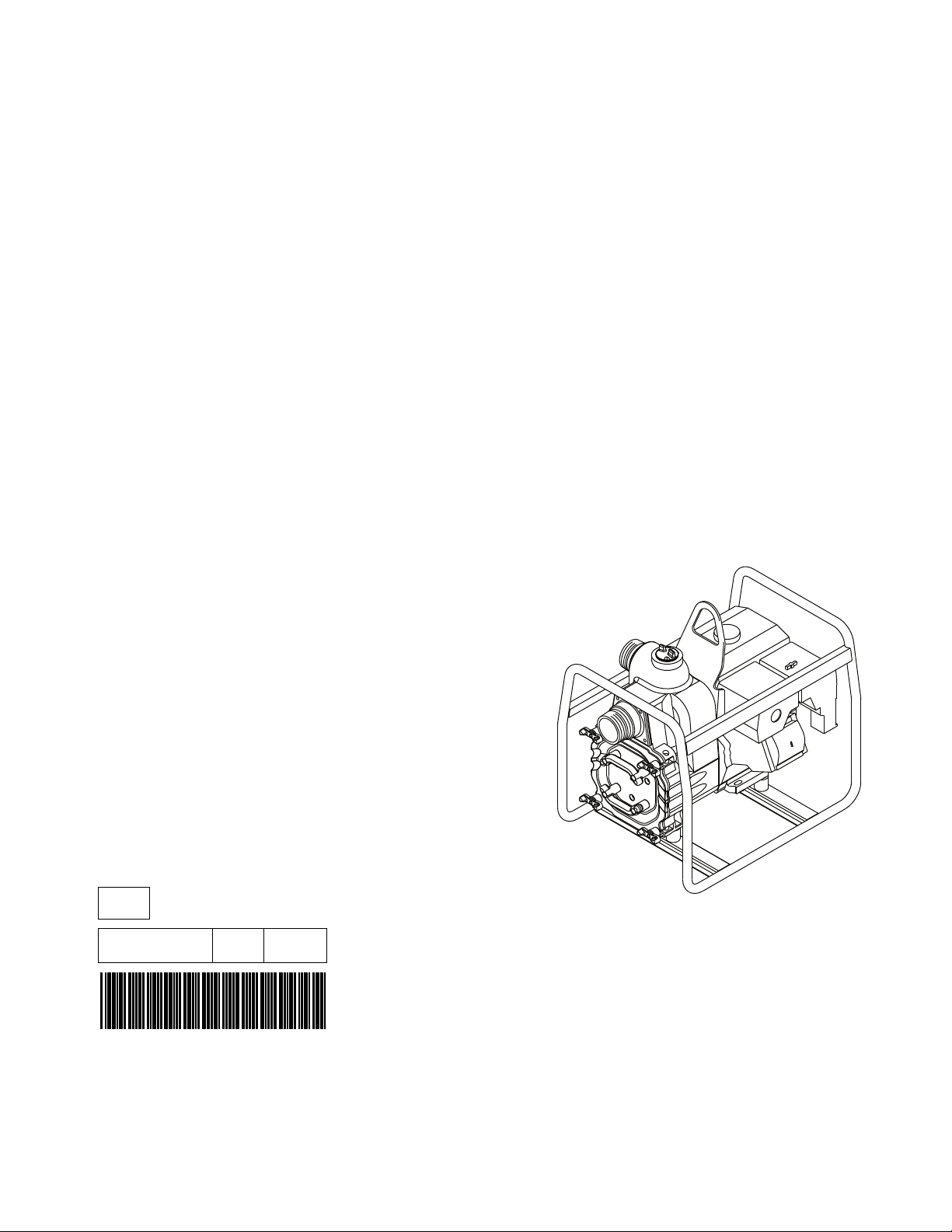
Pump
PT2 / PT2A / PT2H
PT3 / PT3A / PT3H
EN
5100016561 02 0915
Page 2

Copyright
notice
© Copyright 2015 by Wacker Neuson Production Americas LLC
All rights, including copying and distribution rights, are reserved.
This publication may be photocopied by the original purchaser of the machine. Any
other type of reproduction is prohibited without express written permission from
Wacker Neuson Production Americas LLC.
Any type of reproduction or distribution not authorized by Wacker Neuson Production
Americas LLC represents an infringement of valid copyrights. Violators will be
prosecuted.
T ra d emarks
Manufacturer
Original
instructions
All trademarks referenced in this manual are the property of their respective owners.
Wacker Neuson Production Americas LLC
N92W15000 Anthony Avenue
Menomonee Falls, WI 53051 U.S.A.
Tel: (262) 255-0500 · Fax: (262) 255-0550 · Tel: (800) 770-0957
www.wackerneuson.com
This Operator’s Manual presents the original instructions. The original language of this
Operator’s Manual is American English.
Page 3
PT2 / PT3 Foreword
wc_gr012659
MADE IN USA
kg
kW
lbs
hp
gpm
Item Number
Type/Model
Rev.
m
ft
Manuf.Yr.
m3/hr
179096
Serial Number
Foreword
SAVE THESE INSTRUCTIONS—This manual contains important instructions for
the machine models below. These instructions have been written expressly by
Wacker Neuson Production Americas LLC and must be followed during inst allation,
operation, and maintenance of the machines.
Machine Item Number
PT2 5000009318
PT2A, PT2A(I) 5000009092, 5000009095, 5000009237
PT2(I) 5000620725
PT2H, PT2H(I) 5000009094, 5000009097
PT3 5000009321, 5000009322
PT3A, PT3A(I) 5000009098, 5000009101, 5000009240, 5000620800
PT3(I) 5000620726
PT3H, PT3H(I) 5000009100, 5000009103
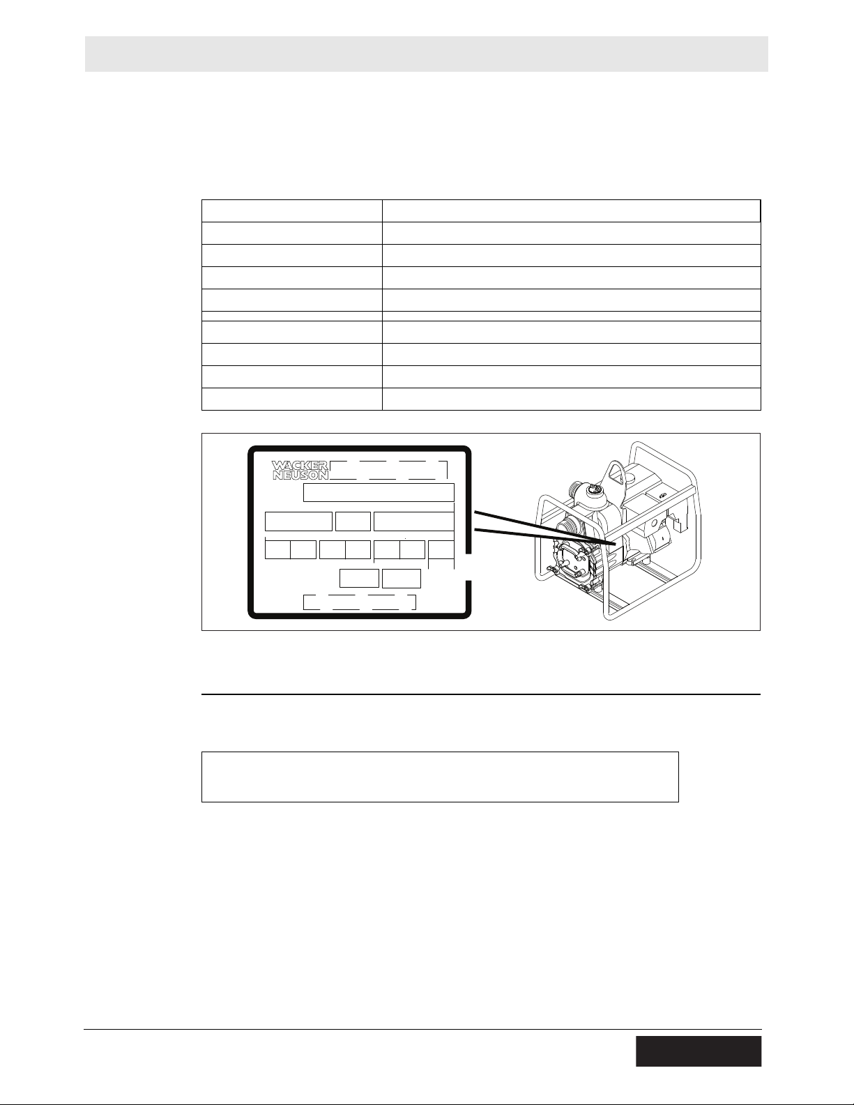
Machine
identification
Serial number
(S/N)
A nameplate listing the model number, item number, revision number, and serial
number is attached to this machine. The location of the nameplate is shown above.
For future reference, record the serial number in the space provided below . You will
need the serial number when requesting parts or service for this machine.
Serial Number:
Machine
documentation
From this point forward in this documentation, Wacker Neuson Production
Americas LLC will be referred to as Wacker Neuson.
Keep a copy of the Operator’s Manual with the machine at all times.
For spare parts information, please see your Wacker Neuson Dealer, or visit
the Wacker Neuson website at http://www.wackerneuson.com/.
When ordering parts or requesting service information, be prepared to provide
wc_tx004018gb_FM10.fm 3
the machine model number, item number, revision number, and serial number.
Page 4

Foreword PT2 / PT3
Expectations
for
information in
this manual
CALIFORNIA
Proposition
65 Warning
Laws
pertaining to
spark
arresters
This manual provides information and procedures to safely operate and
maintain the above Wacker Neuson model(s). For your own safety and to
reduce the risk of injury , carefully read, underst and, and observe all instructions
described in this manual.
Wacker Neuson expressly reserves the right to make technical modifications,
even without notice, which improve the performance or safety standards of its
machines.
The information contained in this manual is based on machines manufactured
up until the time of publication. Wacker Neuson reserves the right to change
any portion of this information without notice.
The illustrations, parts, and procedures in this manual refer to Wacker Neuson
factory-installed components. Your machine may vary depending on the
requirements of your specific region.
Combustion exhaust, some of its constituents, and certain vehicle components
contain or emit chemicals known to the State of California to cause cancer and
birth defects or other reproductive harm.
NOTICE: State Health Safety Codes and Public Resources Codes specify that in
certain locations spark arresters be used on internal combustion engines that use
hydrocarbon fuels. A spark arrester is a device designed to prevent accidental
discharge of sparks or flames from the engine exhaust. Spark arresters are
qualified and rated by the United States Forest Service for this purpose. In order to
comply with local laws regarding spark arresters, consult the engine distributor or
the local Health and Safety Administrator.
Manufacturer’s
approval
This manual contains references to approved parts, attachments, and
modifications. The following definitions apply:
Approved parts or attachments are those either manufactured or provided by
Wacker Neuson.
Approved modifications are those performed by an authorized Wacker
Neuson service center according to written instructions published by Wacker
Neuson.
Unapproved parts, attachments, and modifications are those that do not
meet the approved criteria.
Unapproved parts, attachments, or modifications may have the following
consequences:
Serious injury hazards to the operator and persons in the work area
Permanent damage to the machine which will not be covered under warranty
Contact your Wacker Neuson dealer immediately if you have questions about
approved or unapproved parts, attachments, or modifications.
4 wc_tx004018gb_FM10.fm
Page 5

EC Declaration of Conformity
Manufacturer
Wacker Neuson Production Americas LLC, N92W15000 Anthony Avenue,
Menomonee Falls, Wisconsin 53051 USA
Product
Product
Product category
Product function
Item number
Net installed power
Measured sound power level
Guaranteed sound power level
PT2A, PT2H
Water Pump Units
To pump fluid
5000009095, 5000009097, 5000009 237
PT 2A: 3.6 kW; PT 2H: 3.4 kW
PT 2A: 99 dB(A); PT 2H: 102 dB(A)
PT 2A: 101 dB(A); PT 2H: 103 dB(A)
Conformity Assessment Procedure
According to 2000/14/EC ANNEX V
Directives and Standards
We hereby declare that this product meets and complies with the relevant regulations and
requirements of the following directives and standards:
2006/42/EC, 2000/14/EC
Authorized Person for Technical Documents
Leo Goeschka, Wacker Neuson Produktion GmbH & Co. KG, Preußenstra ß e 41,
80809 München
Menomonee Falls, WI, USA, 24.08.15
Keith Herr
Vice President and Managing Director
For Wacker Neuson
2015-CE-PT2_en_812_FM10.fm
Dan Domanski
Technical Director
For Wacker Neuson
Travis Pound
Manager, Product Engineering
For Wacker Neuson
Original Declaration of Conformity
Page 6

Page 7

EC Declaration of Conformity
Manufacturer
Wacker Neuson Production Americas LLC, N92W15000 Anthony Avenue,
Menomonee Falls, Wisconsin 53051 USA
Product
Product
Product category
Product function
Item number
Net installed power
Measured sound power level
Guaranteed sound power level
PT3, PT3A, PT3H
Water Pump Units
To pump fluid
5000009101, 5000009240, 5000009103, 5000009322,
5000620800
PT 3: 6.6 kW; PT 3A: 5.9 kW; PT 3H: 5.0 kW
PT 3: 102 dB(A); PT 3A: 101 dB(A); PT 3H: 106 dB(A)
PT 3: 103 dB(A); PT 3A: 102 dB(A); PT 3H: 106 dB(A)
Conformity Assessment Procedure
According to 2000/14/EC ANNEX V
Directives and Standards
We hereby declare that this product meets and complies with the relevant regulations and
requirements of the following directives and standards:
2006/42/EC, 2000/14/EC
Authorized Person for Technical Documents
Leo Goeschka, Wacker Neuson Produktion GmbH & Co. KG, Preußenstra ß e 41,
80809 München
Menomonee Falls, WI, USA, 27.03.15
Keith Herr
Vice President and Managing Director
For Wacker Neuson
2015-CE-PT3_en_FM10.fm
Dan Domanski
Technical Director
For Wacker Neuson
Travis Pound
Manager, Product Engineering
For Wacker Neuson
Original Declaration of Conformity
Page 8

Page 9

PT2 / PT3
Table of Contents
Foreword 3
EC Declaration of Conformity 5
EC Declaration of Conformity 7
1 Safety Information 11
1.1 Signal Words Used in this Manual ..................................................... 11
1.2 Machine Description and Intended Use ............................................. 12
1.3 Safety Guidelines for Operating the Machine ..................................... 13
1.4 Service Safety .................................................................................... 15
1.5 Operator Safety while Using Internal Combustion Engines ............... 17
2 Labels 18
2.1 Label Locations ................................................................................... 18
2.2 Label Meanings .................................................................................. 19
3 Lifting and Transporting 22
3.1 Lifting the Machine ............................................................................. 22
3.2 Preparing the Machine for Transport on a Truck or Trailer ................ 23
4 Operation 24
4.1 Preparing the Machine for First Use ................................................... 24
4.2 Recommended Fuel ........................................................................... 25
4.3 Recommended Fuel (Hatz powered machines only) ......................... 25
4.4 Refueling the Machine ........................................................................ 26
4.5 Positioning and Preparing the Machine for Operation ........................ 27
4.6 Before Starting the Machine ............................................................... 28
4.7 Starting and Stopping the Machine (WM 170 / WM 270) ................... 29
4.8 Starting and Stopping the Machine (Honda) ...................................... 30
4.9 Starting and Stopping the Machine (Hatz) ......................................... 31
4.10 Emergency Shutdown Procedure ....................................................... 32
5 General Maintenance 33
5.1 Maintaining the Emission Control System .......................................... 33
5.2 Periodic Maintenance Schedule ......................................................... 33
wc_bo5100016561_02_FM10TOC.fm
9
Page 10

Table of Contents
5.3 Inspecting the Impeller ........................................................................34
5.4 Storage ...............................................................................................36
5.5 Machine Disposal and Decommissioning ...........................................37
PT2 / PT3
6 Engine Maintenance: WM 130 / WM 170 / WM 270 38
7 Engine Maintenance: Honda GX160 40
8 Engine Maintenance: Honda GX390 42
9 Engine Maintenance: Hatz 1B 20 / 1B 30 44
10 Troubleshooting 47
11 Technical Data 48
11.1 Engine—PT2 / PT2(I) / PT2H / PT2H(I) ..............................................48
11.2 Engine—PT2A / PT2A(I) .....................................................................49
11.3 Engine—PT3 / PT3A / PT3(I) / PT3H .................................................50
11.4 Pump—PT2 / PT2(I) / PT2A / PT2H ...................................................51
11.5 Pump—PT3 / PT3(I) / PT3A / PT3H ...................................................51
11.6 Sound Measurements .........................................................................52
11.7 Dimensions .........................................................................................53
12 Emission Control Systems Information
and Warranty 55
12.1 Emission Control Systems Warranty Statement .................................55
13 AEM Safety Manual 57
10
wc_bo5100016561_02_FM10TOC.fm
Page 11
PT2 / PT3 Safety Information
1 Safety Information
1.1 Signal Words Used in this Manual
This manual contains DANGER, WARNING, CAUTION, NOTICE, and NOTE
signal words which must be followed to reduce the possibility of personal injury,
damage to the equipment, or improper service.
This is the safety alert symbol. It is used to alert you to potential personal hazards.
► Obey all safety messages that follow this symbol.
DANGER
DANGER indicates a hazardous situation which, if not avoided, will result in death
or serious injury.
► To avoid death or serious injury from this type of hazard, obey all safety
messages that follow this signal word.
WARNING
WARNING indicates a hazardous situation which, if not avoided, could result in
death or serious injury.
► To avoid possible death or serious injury from this type of hazard, obey all safety
messages that follow this signal word.
CAUTION
CAUTION indicates a hazardous situation which, if not avoided, could result in
minor or moderate injury.
► To avoid possible minor or moderate injury from this type of hazard, obey all
safety messages that follow this signal word.
NOTICE: Used without the safety alert symbol, NOTICE indicates a situation
which, if not avoided, could result in property damage.
Note: A Note contains additional information important to a procedure.
wc_si000938gb_FM10.fm
11
Page 12

Safety Information PT2 / PT3
1.2 Machine Description and Intended Use
This machine is a centrifugal trash pump. The Wacker Neuson Trash Pump
consists of a tubular steel frame surrounding a gasoline or diesel engine, a fuel
tank, and an impeller pump with ports for water suction and discharge. The engine
rotates the impeller during operation. Waste water is drawn into the pump through
the suction port and expelled through the discharge port. The operator connects
hoses to the pump and routes them so that water and solids are drained from the
work area and discharged into an appropriate location.
This machine is intended to be used for general de-watering applications. This
machine is intended for the pumping of clear water , or water containing solids up to
the size stated within the product specifications, and up to the flow, head, and
suction lift limits also stated within the product specifications.
This machine has been designed and built strictly for the intended use described
above. Using the machine for any other purpose could permanently damage the
machine or seriously injure the operator or other persons in the area. Machine
damage caused by misuse is not covered under warranty.
The following are some examples of misuse:
■ Pumping flammable, explosive, or corrosive fluids
■ Pumping hot or volatile fluids that result in pump cavitation
■ Operating the pump outside of product specifications due to incorrect diameter
hoses, incorrect length hoses, other inlet or outlet restrictions, or excessive
suction lift or head
■ Using the machine as a ladder, support, or work surface
■ Operating the machine outside of factory specifications
■ Operating the machine in a manner inconsistent with all warnings found on the
machine and in the Operator’s Manual
This machine has been designed and built in accordance with the latest global
safety standards. It has been carefully engineered to eliminate hazards as far as
practicable and to increase operator safety through protective guards and labeling.
However, some risks may rema in even after protective measures have been t aken.
They are called residual risks. On this machine, they may include exposure to:
■ Heat, noise, exhaust, and carbon monoxide from the engine
■ Fire hazards from improper refueling techniques
■ Fuel and its fumes
■ Personal injury from improper lifting techniques
■ Projectile hazard from discharge
■ Crushing hazards from a tipping or falling pump
To protect yourself and others, make sure you thoroughly read and understand the
safety information presented in this manual before operating the machine.
wc_si000938gb_FM10.fm
12
Page 13

PT2 / PT3 Safety Information
1.3 Safety Guidelines for Operating the Machine
Operator
training
Operator
qualifications
Application
area
Before operating the machine:
■ Read and understand the operating instructions contained in all manuals
delivered with the machine.
■ Familiarize yourself with the location and proper use of all controls and safety
devices.
■ Contact Wacker Neuson for additional training if necessary.
When operating this machine:
■ Do not allow improperly trained people to operate the machine. People
operating the machine must be familiar with the potential risks and hazards
associated with it.
Only trained personnel are permitted to start, operate, and shut down the machine.
They also must meet the following qualifications:
■ have received instruction on how to properly use the machine
■ are familiar with required safety devices
The machine must not be accessed or operated by:
■ children
■ people impaired by alcohol or drugs
Be aware of the application area.
■ Keep unauthorized personnel, children, and pets away from the machine.
■ Remain aware of changing positions and the movement of other equipment and
personnel in the application area/job site.
■ Identify whether special hazards exist in the application area, such as toxic
gases or unstable ground conditions, and take appropriate action to eliminate
the special hazards before using the machine.
Be aware of the application area.
■ Do not operate the machine in areas that contain flammable objects, fuels, or
Safety
devices,
controls, and
attachments
Only operate the machine when:
■ All safety devices and guards are in place and in working order.
■ All controls operate correctly.
■ The machine is set up correctly according to the instructions in the Operator’s
■ The machine is clean.
■ The machine’s labels are legible.
To ensure safe operation of the machine:
■ Do not operate the machine if any safety devices or guards are missing or
■ Do not modify or defeat the safety devices.
■ Only use accessories or attachments that are approved by Wacker Neuson.
wc_si000938gb_FM10.fm
products that produce flammable vapors.
Manual.
inoperative.
13
Page 14

Safety Information PT2 / PT3
Safe
operating
practices
Personal
Protective
Equipment
(PPE)
Safe
operating
practices
When operating this machine:
■ Remain aware of the machine’s moving parts. Keep hands, feet, and loose
clothing away from the machine’s moving parts.
When operating this machine:
■ Do not operate a machine in need of repair.
Wear the following Personal Protective Equipment (PPE) while operating this
machine:
■ Close-fitting work clothes that do not hinder movement
■ Safety glasses with side shields
■ Hearing protection
■ Safety-toed footwear
■ Do not open the priming plug when the pump is hot. Do not loosen or remove
inlet or discharge hose fittings when the pump is hot. Hot water inside could be
pressurized much like the radiator on an automobile. Allow the pump to cool to
the touch before loosening the plug and before loosening or removing the inlet
or discharge hose fittings.
■ Do not position the pump on a loose, uneven, or unstable surface where it can
tip, roll, slide or fall! The pump must be secure before operating. Position the
pump on a firm and flat surface
■ Do not open the pump housing cover while the pump is operating or start the
pump with the cover off. The rotating impeller inside the pump can cut or sever
objects caught in it.
■ Do not block or restrict flow from the inlet line or the discharge line. Remove
kinks from the discharge line before starting the pump. Operation with a blocked
inlet line or discharge line can cause water inside the pump to overheat.
■ Do not reach into or insert anything into the pump while the engine is on! The
impeller inside the pump housing is turning at all times while the engine is
running.
■ Do not allow anyone to stand in front of the discharge port when starting the
engine or while priming the pump! The sudden out-rush of water could push or
knock a person down.
■ Always make sure the hose connections on the pump are tight. A loose
connection could cause water to spray or result in a hose falling off the pump
while it is in operation.
■ Always make sure the water stream from the pump discharge is not directed in
such a way so as to cause erosion to the surrounding ground or damage or
weakening of nearby structures!
14
wc_si000938gb_FM10.fm
Page 15

PT2 / PT3 Safety Information
1.4 Service Safety
Service
training
Precautions
Before servicing or maintaining the machine:
■ Read and understand the instructions contained in all manuals delivered with
the machine.
■ Familiarize yourself with the location and proper use of all controls and safety
devices.
■ Only trained personnel shall troubleshoot or repair problems occurring with the
machine.
■ Contact Wacker Neuson for additional training if necessary.
When servicing or maintaining this machine:
■ Do not allow improperly trained people to service or maintain the machine.
Personnel servicing or maintaining the machine must be familiar with the
associated potential risks and hazards.
When servicing or maintaining the machine:
■ Read and understand the service procedures before performing any service to
the machine.
■ All adjustments and repairs must be completed before operating the machine.
Do not operate the machine with a known problem or deficiency.
■ All repairs and adjustments shall be completed by a qualified technician.
■ Turn off the machine before performing maintenance or making repairs.
■ Remain aware of the machine’s moving parts. Keep hands, feet, and loose
clothing away from the machine’s moving parts.
■ Re-install the safety devices and guards after repair and maintenance
procedures are complete.
Machine
modifications
Replacing
parts and
labels
When servicing or maintaining the machine:
■ Use only accessories/attachments that are approved by Wacker Neuson.
When servicing or maintaining the machine:
■ Do not defeat safety devices.
■ Do not modify the machine without the express written approval of Wacker
Neuson.
■ Replace worn or damaged components.
■ Replace all missing and hard-to-read labels.
■ When replacing electrical components, use components that are identical in
rating and performance to the original components.
■ When replacement parts are required for this machine, use only Wacker
Neuson replacement parts or those p arts equivalent to the original in a ll types of
specifications, such as physical dimensions, type, strength, and material.
wc_si000938gb_FM10.fm
15
Page 16

Safety Information PT2 / PT3
Cleaning
Personal
Protective
Equipment
(PPE)
After Use
When cleaning and servicing the machine:
■ Keep the machine clean and free of debris such as leaves, paper, cartons, etc.
■ Keep the labels legible.
When cleaning the machine:
■ Do not clean the machine while it is running.
■ Never use gasoline or other types of fuels or flammable solvents to clean the
machine. Fumes from fuels and solvents can become explosive.
Wear the following Personal Protective Equipment (PPE) while servicing or
maintaining this machine:
■ Close-fitting work clothes that do not hinder movement
■ Safety glasses with side shields
■ Hearing protection
■ Safety-toed footwear
In addition, before servicing or maintaining the machine:
■ Tie back long hair.
■ Remove all jewelry (including rings).
■ Stop the engine when the machine is not being operated.
■ Close the fuel valve on engines equipped with one when machine is not being
operated.
■ Ensure that the machine will not tip over, roll, slide, or fall when not being
operated.
■ Store the machine properly when it is not being used. The machine should be
stored in a clean, dry location out of the reach of children.
16
wc_si000938gb_FM10.fm
Page 17
PT2 / PT3 Safety Information
1.5 Operator Safety while Using Internal Combustion Engines
WARNING
Internal combustion engines present special hazards during operation and fueling.
Failure to follow the warnings and safety standards could result in severe injury or
death.
► Read and follow the warning instructions in the engine owner’s manual and the
safety guidelines below.
DANGER
Exhaust gas from the engine contains carbon monoxide, a deadly poison.
Exposure to carbon monoxide can kill you in minutes.
► NEVER operate the machine inside an enclosed area, such as a tunnel, unless
adequate ventilation is provided through such items as exhaust fans or hoses.
Operating
safety
Refueling
safety
When running the engine:
■ Keep the area around the exhaust pipe free of flammable materials.
■ Check the fuel lines and the fuel tank for leaks and cracks before starting the
engine. Do not run the machine if fuel leaks are present or the fuel lines are
loose.
When running the engine:
■ Do not smoke while operating the machine.
■ Do not run the engine near sparks or open flames.
■ Do not touch the engine or muffler while the engine is running or immediately
after it has been turned off.
■ Do not operate a machine when its fuel cap is loose or missing.
■ Do not start the engine if fuel has spilled or a fuel odor is present. Move the
machine away from the spill and wipe the machine dry before starting.
When refueling the engine:
■ Clean up any spilled fuel immediately.
■ Refill the fuel tank in a well-ventilated area.
■ Re-install the fuel tank cap after refueling.
■ Do not smoke.
■ Do not refuel a hot or running engine.
■ Do not refuel the engine near sparks or open flames.
■ Use suitable tools for refueling (for example, a fuel hose or a funnel).
■ Do not refuel if the machine is positioned in a truck fitted with a plastic bed liner.
Static electricity can ignite the fuel or fuel vapors.
wc_si000938gb_FM10.fm
17
Page 18
Labels PT2 / PT3
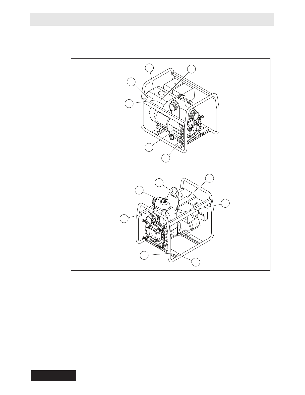
wc_gr012671
A
B
C
D
E
F
G
H
D
C
J
K
M
2 Labels
2.1 Label Locations
18
wc_si000939gb_FM10.fm
Page 19
PT2 / PT3 Labels
GEFAHRGEFAHR
DANGERDANGER
117034
HONDA
DANGERDANGER
STOPSTOP
PELIGROPELIGRO
STOP
117039
ADVERTENCIAADVERTENCIA
AVERTISSEMENTAVERTISSEMENT
WARNINGWARNING
178713
ATTENTIONATTENTION
CAUTIONCAUTION
VORSICHTVORSICHT
ATENCIONATENCION
110167110167
178714178714
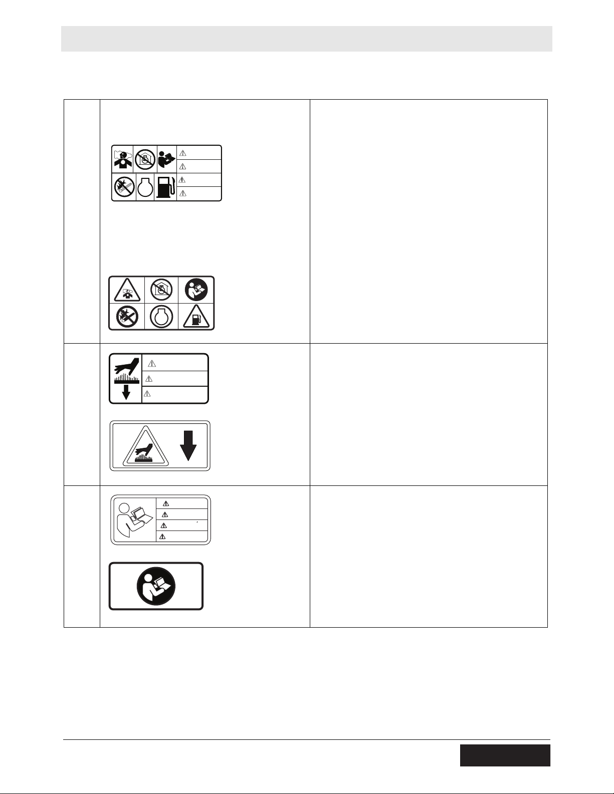
2.2 Label Meanings
DANGER
Asphyxiation hazard.
■ Engines emit carbon monoxide.
■ Do not run the machine indoors or in an
enclosed area.
■ NEVER use inside a home or garage, EVEN IF
doors and windows are open.
■ Only use OUTSIDE and far away from windows,
doors, and vents.
A
STOP
178715
■ Read the Operator’s Manual.
■ No sparks, flames, or burning objects near the
machine.
■ Stop the engine before refueling.
■ Use only clean, filtered diesel fuel.
WARNING
Hot surface
B
178713
CAUTION
Read and understand the supplied Operator’s
Manual before operating this machine. Failure to
do so increases the risk of injury to yourself and
others.
C
wc_si000939gb_FM10.fm
19
Page 20

Labels PT2 / PT3
110164
ADVERTENCIA
AVERTISSEMENT
WARNING
5100015564
ADVERTENCIAADVERTENCIA
WARNUNGWARNUNG
110164110164
WARNINGWARNING
AVERTISSEMENTAVERTISSEMENT
5100015565
NE JAMAIS POMPER DESNE JAMAIS POMPER DES
LIQUIDES VOLATILES, LIQUIDES VOLATILES,
INFLAMMABLES OU A BAS POINT INFLAMMABLES OU A BAS POINT
CES LIQUIDES CES LIQUIDES
POURRAIENT PRENDRE FEU OU POURRAIENT PRENDRE FEU OU
EXPLOSER.EXPLOSER.
NUNCA BOMBEAR LIQUIDOS NUNCA BOMBEAR LIQUIDOS
VOLATILES INFLAMABLES O DE VOLATILES INFLAMABLES O DE
PUNTO BAJO DE ENCENDIDO. PUNTO BAJO DE ENCENDIDO.
ESTOS FLUIDOS PUEDEN ESTOS FLUIDOS PUEDEN
ENCENDERSE O EXPLOTAR.ENCENDERSE O EXPLOTAR.
AVERTISSEMENTAVERTISSEMENT
ADVERTENCIAADVERTENCIA
151049151049
NEVER PUMP VOLATILE, NEVER PUMP VOLATILE,
FLAMMABLE OR LOW FLASH FLAMMABLE OR LOW FLASH
POINT FLUIDS. THESE FLUIDSPOINT FLUIDS. THESE FLUIDS
COULD IGNITE OR EXPLODE.COULD IGNITE OR EXPLODE.
WARNUNGWARNUNG
WARNINGWARNING
178764178764
181145
WARNING
WARNING
ADVERTENCIA
AVERTISSEMENT
110164
D
5100015564
5100015565
Pressurized contents. Do not open when hot!
WARNING
Never pump volatile, flammable, or low-flash-point
fluids. These fluids could ignite or explode.
E
CAUTION
Use only clean, filtered diesel fuel
(Hatz powered machines only)
F
181145
20
wc_si000939gb_FM10.fm
Page 21
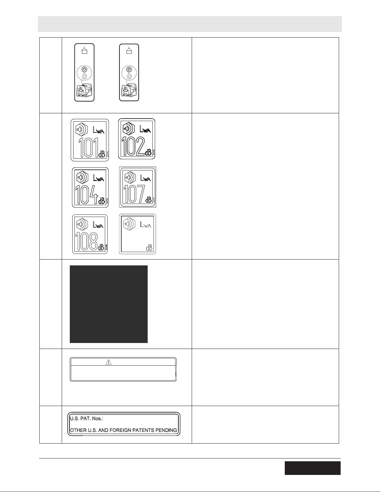
PT2 / PT3 Labels
5200015473 PT2
73 kg
(160 LBS)
5200015474 PT3
91 kg
(200 LBS)
WARNING
Operation of This Equipment May Create Sparks That Can Start Fires Around Dry
Vegetation. A Spark Arrestor May be Required. The Operator Should Contact Local
Fire Agencies For Laws or Regulations Relating to Fire Prevention Requirements.
Per CAL. PRC. CODE
NOTICE
73 kg
(160 LBS)
91 kg
(200 LBS)
G
Lifting point
5200015473 PT2
5200015474 PT3
Guaranteed sound power level in dB(A)
H
99
153789
Certified Performance
Contractors Pump Bureau
A Bureau of AEM
The manufacturer of this pump certifies that it was
manufactured in accordance with the standards of
J
the Contractors Pump Bureau.
K
M
wc_si000939gb_FM10.fm
WARNING
Operation of this equipment may create sparks that
can start fires around dry vegeta tion. A spark
arrester may be required. The operator should
contact local fire agencies for laws or regulations
relating to fire prevention requirements.
This machine may be covered by one or more
patents.
21
Page 22

Lifting and Transporting PT2 / PT3
wc_gr012660
3 Lifting and Transporting
3.1 Lifting the Machine
Requirements
Lifting the
machine
■ Lifting equipment (crane, hoist, or fork truck) capable of supporting the
machine’s weight
■ Lifting devices (hooks, chains, and shackles) capable of supporting the
machine’s weight
■ Engine stopped
A lifting eye is used for lifting the machine.
Perform the procedure below to lift the machine.
1. Attach the lifting devices and equipment to the lifting eye. Do not attach lifting
devices to any other part of the machine.
2. Lift the machine a small distance.
WARNING
Crushing hazard. An unstable machine may cause the lifting devices and
equipment to fail. You may be crushed if the lifting devices and equipment fail.
► Check for stability before continuing.
3. Check for stability . If necessary, lower the machine, reposition the lifting devices,
and lift the machine a small distance again.
4. Continue lifting the machine only when it is stable.
22
wc_tx004019gb_FM10.fm
Page 23

PT2 / PT3 Lifting and Transporting
3.2 Preparing the Machine for Transport on a Truck or Trailer
Requirements
Checklist
■ Machine stopped
■ Flatbed truck or trailer capable of supporting the machine’s weight
■ Chains, hooks, or straps capable of supporting the machine’s weight
Before transporting the machine, check the following items:
Check that the transport vehicle or trailer can support the weight of the machine.
Check that the transport vehicle or trailer is wide enough to support the
machine.
Check that the wheels of the transport vehicle or trailer are chocked during the
loading process.
Check that the transport vehicle or trailer is clean and free of grease, oil, ice,
and other loose material.
Check that any ramps used in the loading process:
■ Can support the weight of the machine.
■ Are clean and free of grease, oil, ice, and other loose material.
■ Are securely connected to the transport vehicle or trailer.
■ Are of sufficient length to keep the loading angle 15° or less.
In addition:
Check that the loading area is flat and the ground is stable.
Check the overall height of the machine once it is loaded on the truck or trailer.
Plan your travel route so there will be adequate clearance for overpasses, road
signs, buildings, etc.
Check local regulations regarding transporting and obey these regulations.
wc_tx004019gb_FM10.fm
23
Page 24

Operation PT2 / PT3
4 Operation
4.1 Preparing the Machine for First Use
1. Make sure all loose packaging materials have been removed from the machine.
2. Check the machine and its components for damage. If there is visible damage,
do not operate the machine! Contact your Wacker Neuson dealer immediately
for assistance.
3. Take inventory of all items included with the machine and verify that all loose
components and fasteners are accounted for.
4. Attach component parts not already attached.
5. Add fluids as needed and applicable, such as fuel and engine oil.
6. Move the machine to its operating location.
24
wc_tx004020gb_FM10.fm
Page 25

PT2 / PT3 Operation
4.2 Recommended Fuel
The engine requires regular grade unleaded gasoline. Use only fresh, clean
gasoline. Gasoline containing water or dirt will damage the fuel system. Consult the
engine owner’s manual for complete fuel specifications.
Use of
oxygenated
fuels
Some conventional gasolines are blended with alcohol. These gasolines are
collectively referred to as oxygenated fuels. If you use an oxygenated fuel, be sure
it is unleaded and meets the minimum octane rating requirement.
Before using an oxygenated fuel, confirm the fuel’s contents. Some states and
provinces require this information to be posted on the fuel pump.
The following is the Wacker Neuson approved percentage of oxygenates:
ETHANOL - (ethyl or grain alcohol) 10% by volume. You may use gasoline
containing up to 10% ethanol by volume (commonly referred to as E10). Gasoline
containing more than 10% ethanol (such as E15, E20, or E85) may not be used
because it could damage the engine.
If you notice any undesirable operating symptoms, try another service station, or
switch to another brand of gasoline.
Fuel system damage or performance problems resulting from the use of an
oxygenated fuel containing more than the percentages of oxygenates mentioned
above are not covered under warranty.
4.3 Recommended Fuel (Hatz powered machines only)
Low temperatures cause diesel fuel to gel. Always use the proper fuel for the
conditions. Follow the guidelines in the table below.
Lowest expected ambient
temperature
Above freezing
> 0°C (32°F)
Below freezing
< 0°C (32°F)
1
Your engine may require ultra low sulfur fuel. Consult the engine owner’s manual.
Recommended fuel
#2 diesel plus additives
Winter-blend diesel
1
CAUTION
Fire hazard.
► Do not use gasoline, crankcase oil, or any oil containing gasoline.
wc_tx004020gb_FM10.fm
25
Page 26

Operation PT2 / PT3
wc_gr012714
a
4.4 Refueling the Machine
Requirements
Procedure
■ Machine shut down
■ Engine cool
■ Machine/fuel tank level with the ground
■ Fresh, clean fuel supply
Perform the procedure below to refuel the machine.
WARNING
Fire hazard. Fuel and its vapors are extremely flammable. Burning fuel can cause
severe burns.
► Keep all sources of ignition away from the machine while refueling.
► Do not refuel if the machine is positioned in a truck fitted with a plastic bed liner.
Static electricity can ignite the fuel or fuel vapors.
► Refuel only when the machine is outdoors.
► Clean up spilled fuel immediately.
1. Remove the fuel cap (a).
2. Fill the fuel tank to the base of the neck.
CAUTION
Fire and health hazard. Fuel expands when heated. Expanding fuel in an ove r-filled
tank can lead to spills and leaks.
► Do not overfill the fuel tank.
3. Re-install the fuel cap.
Result
The procedure to refuel the machine is now complete.
wc_tx004020gb_FM10.fm
26
Page 27

PT2 / PT3 Operation
wc_gr012715
d
a
b
c
e
f
g
4.5 Positioning and Preparing the Machine for Operation
WARNING
Personal injury hazard. Failure to follow the listed procedures may cause injury to
personnel or damage to the machine.
► All persons setting up the machine must be fully trained on the installation of the
machine.
Pre-operation
setup
Perform the procedure below to position and prepare the machine for operation.
1. Position the pump as near to the water as possible, on a firm, flat surf ace. Keep
the pump level.
2. Connect the suction hose (a) to the suction port (b).
■ Suction hoses must be rigid enough not to collapse.
■ At least two T-bolt clamp s are recommended for connecting the suction hose
to the suction port. Position the hose clamps at 90° intervals for best seal.
wc_tx004020gb_FM10.fm
WARNING
Personal injury hazard. A loose connection between the suction hose and the
suction port can result in personal injury should the suction hose break loose while
the pump is operating.
► Only operate the machine when the suction hose is securely fastened to the
suction port.
This procedure continues on the next page.
27
Page 28

Operation PT2 / PT3
Continued from the previous page.
3. Connect the strainer (c) to the suction hose.
■ Always use a strainer on the end of the suction hose to prevent pulling in
large debris which could clog the pump or jam the impeller.
■ Do not use a strainer with holes larger than the maximum solid-size rating of
the pump.
Machine Maximum solid-size rating
PT2 25 mm (1.0 in.)
PT3 38 mm (1.5 in.)
4. Submerge the suction hose.
■ Do not place the strainer directly into mud or sand. Always keep the strainer
suspended (d) in the liquid being pumped.
5. Connect the discharge hose (e) to the discharge port (f).
Note: Lay the discharge hose as straight as possible. Avoid sharp bends and
turns.
6. Prime the pump. To do so:
a.Remove the priming plug (g).
b.With the suction hose submerged, fill the pump housing with water.
c.Close the priming plug.
4.6 Before Starting the Machine
Before starting the machine, perform each item on the following checklist.
Pre-operation
checks
External
checks
Internal
checks
Read and understand the engine owner’s manual.
Review and follow the safety instructions found in the front of this Operator’s
Manual.
Check the suction hose and discharge hose for holes or tears.
Make sure that the hose couplings and hose clamps are attached.
Check that the priming plug is closed.
Check the tightness of the external fasteners—tighten the external fasteners as
necessary.
Check engine oil and fuel levels—fill as required.
Check the condition of the air cleaner—remove debris or replace air cleaner.
28
wc_tx004020gb_FM10.fm
Page 29

PT2 / PT3 Operation
wc_gr012716
e
d
1
d
2
c
2
c
1
b
2
b
1
a
2
a
1
d
3
4.7 Starting and Stopping the Machine (WM 170 / WM 270)
Requirements
Starting the
machine
■ Suction and discharge hoses properly attached and positioned
■ There is fuel in the tank
Perform the procedure below to start the machine.
1. Set the fuel valve to the open position (a
).
1
Note: If the engine is cold, set the choke lever to the closed position (b
engine is hot, set the choke lever to the open position (b
).
2
). If the
1
2. Turn the engine start switch to the “ON” position (c
3. Move the throttle lever slightly to the left (d
4. Pull the starter rope (e).
Note: If the oil level in the engine is low, the engine will not start. If this happens,
add oil to the engine.
5. Open the choke (b
6. Set the throttle lever to the high speed position (d
Stopping the
machine
Perform the procedure below to stop the machine.
1. Set the throttle lever to the slow/idle position (d
2. Turn engine start switch to the “OFF” position (c
3. Set the fuel valve to the closed position (a
wc_tx004020gb_FM10.fm
high speed position (d
).
1
) as the engine warms.
1
29
).
1
), about 1/3 of the way toward the
2
) to operate the machine.
1
) to reduce engine RPM.
3
).
2
).
2
Page 30

Operation PT2 / PT3
wc_gr012718
c
1
c
2
d
2
d
3
e
b
1
b
2
a
1
a
2
f
d
1
4.8 Starting and Stopping the Machine (Honda)
Requirements
Starting the
machine
■ Suction and discharge hoses properly attached and positioned
■ There is fuel in the tank
Perform the procedure below to start the machine.
1. Set the fuel valve to the open position (a
).
1
Note: If the engine is cold, set the choke lever to the closed position (b
engine is hot, set the choke lever to the open position (b
).
2
). If the
1
2. Turn the engine start switch to the “ON” position (c
3. Move the throttle lever slightly to the left (d
high speed position (d
).
1
), about 1/3 of the way toward the
2
).
1
4. Pull the starter rope (e).
Note: If the oil level in the engine is low, the engine will not start. If this happens,
Stopping the
machine
add oil to the engine. Y our engine may be equipped with an oil alert light (f) that will
illuminate while pulling the starter rope.
5. Open the choke (b
) as the engine warms.
1
6. Set the throttle lever to the high speed position (d
) to operate the machine.
1
Perform the procedure below to stop the machine.
1. Set the throttle lever to the slow/idle position (d
2. Turn engine start switch to the “OFF” position (c
3. Set the fuel valve to the closed position (a
) to reduce engine RPM.
3
).
2
).
2
wc_tx004020gb_FM10.fm
30
Page 31

PT2 / PT3 Operation
wc_gr012719
a
b
1/2
StartStop
4.9 Starting and Stopping the Machine (Hatz)
Requirements
Starting the
machine
■ Suction and discharge hoses properly attached and positioned
■ There is fuel in the tank
Perform the procedure below to start the machine.
1. Set the engine speed control lever (a) to the 1/2 START or START position, as
desired or necessary.
Note: Starting the engine at a lower speed will help to prevent exhaust smoke.
2. Pull the starter rope (b) lightly until you feel slight resistance.
Stopping the
machine
3. Allow the recoil starter to pull the starter rope back in. This allows the entire
length of the starter rope to be used to start the engine.
4. Grip the starter rope handle with both hands.
5. Pull the starter rope briskly. Repeat until the engine starts.
Note: If after several attempts to start the engine and exhaust begins to emit white
smoke, move the speed control lever to the STOP position. Then, pull the starter
rope out slowly 5 times. Repeat the starting the machine procedure at step 1.
Set the engine speed control lever to the STOP position.
wc_tx004020gb_FM10.fm
31
Page 32

Operation PT2 / PT3
4.10 Emergency Shutdown Procedure
Perform the procedure below if a breakdown or accident occurs while the machine
is operating.
1. Stop the engine.
2. Remove the obstruction.
3. Un-kink the hoses.
4. Allow the machine to cool.
5. Contact the rental yard or machine owner.
32
wc_tx004020gb_FM10.fm
Page 33

PT2 / PT3 General Maintenance
5 General Maintenance
WARNING
A poorly maintained machine can malfunction, causing injuries or permanent
damage to the machine.
► Keep the machine in safe operating condition by performing periodic
maintenance and making repairs as needed.
5.1 Maintaining the Emission Control System
For machines sold in North America:
Normal maintenance, replacement, or repair of emission control devices and
systems may be performed by any repair establishment or individual; however,
warranty repairs must be performed by a dealer/service center authorized by
Wacker Neuson. The use of service parts that are not equivalent in performance
and durability to authorized parts may impair the effectiveness of the emission
control system and may have a bearing on the outcome of a warranty claim.
5.2 Periodic Maintenance Schedule
The table below lists basic machine and engine maintenance. Tasks designated
with check marks may be performed by the operator . Tasks designated with square
bullet points require special training and equipment.
Refer to the engine owner’s manual for additional information.
Check external hardware.
Open pump housing cover and remove any debris from
inside of pump housing.
Inspect for leaks between pump and engine.
Check the condition of the fuel tank cap and drain plug
cap.
Check housing cover O-rings.
Inspect shockmounts for damage.
Daily before starting
wc_tx004021gb_FM10.fm
33
Page 34

General Maintenance PT2 / PT3
wc_gr012673
a
b
5.3 Inspecting the Impeller
Background
Requirements
Procedure
Sand, dirt, and debris will cause the impeller to wear. If the pump’s performance
drops over time, check and adjust the clearance between the impeller and the
insert.
■ Machine shut down
■ Bleach and source of clean water
■ Shims (if needed)
WARNING
Personal injury hazard.
► Do not reach into or insert anything into the pump while the engine is running.
► Do not run the pump with the pump housing cover removed.
Perform the procedure below to inspect the impeller.
1. Open the drain plug (a) and drain the pump.
2. Remove the pump housing cover (b) from the front of the pump.
WARNING
Personal injury hazard. Impeller edges can become sharp.
► Use care when working on the pump to reduce the risk of being cut.
This procedure continues on the next page.
34
wc_tx004021gb_FM10.fm
Page 35

PT2 / PT3 General Maintenance
wc_gr012674
d
e
c
Continued from the previous page.
3. Remove the volute (c) and clean the impeller (d) with a 50-50 mixture of bleach
and water before working on it.
Note:
Result
4. Check clearance between the impeller and the insert by slowly pulling the
starter rope to turn the impeller. If starter rope is difficult to pull, or rubbing is
heard from inside pump, the impeller and insert are too close to each other.
Remove a shim (e) from behind the insert and check again for rubbing.
Continue removing shims until the impeller turns easily.
■ It is important not to remove too many shims or the clearance between the
impeller and the insert will become too wide and pump performance will be
reduced.
■ As the impeller wears down, additional shims may be required to maintain the
clearance between the impeller and the insert.
5. Re-install the pump housing cover.
The impeller has now been inspected.
wc_tx004021gb_FM10.fm
35
Page 36

General Maintenance PT2 / PT3
5.4 Storage
Introduction
When
Preparing for
storage
Extended storage of equipment requires preventive maintenance. Performing
these steps helps to preserve machine components and ensures the machine will
be ready for future use. While not all of these steps necessarily apply to this
machine, the basic procedures remain the same.
Prepare your machine for extended storage if it will not be operated for 30 days or
more.
Follow the procedures below to prepare your machine for storage.
■ Complete any needed repairs.
■ Replenish or change oils (engine, exciter, seal and bearing housings, and
gearcase) per the intervals specified in the Periodic Maintenance Schedule.
■ Grease all fittings and, if applicable, repack bearings.
■ Inspect engine coolant. Replace coolant if it appears cloudy, is more than two
seasons old, or does not meet the average lowest temperature for your area.
■ If your machine has an engine equipped with a fuel valve, start the engine, close
the fuel valve, and run the engine until it stops.
■ Flush the pump and the hose lines by pumping clean water for a few minutes. If
the pump was used for pumping salt water, be sure to use fresh water when
flushing it.
■ Remove the covers and clean the pump’s interior. Wipe or spray all interior
surfaces with a rust-inhibiting oil.
■ Consult the engine owner’s manual for instructions on preparing the engine for
storage.
Stabilizing the
fuel
Storing the
machine
After completing the procedures listed above, fill the fuel tank completely and add a
high-quality stabilizer to the fuel.
■ Choose a stabilizer that includes cleaning agents and additives designed to
coat/protect the cylinder walls.
■ Make sure the stabilizer you use is compatible with the fuel in your area, fuel
type, grade and temperature range. Do not add extra alcohol to fuels which
already contain it (for example, E10).
■ For engines with diesel fuel, use a stabilizer with a biocide to restrict or prevent
bacteria and fungus growth.
■ Add the correct amount of stabilizer per the manufacturer’s recommendations.
Perform these remaining steps to store your machine.
■ Wash the machine and allow it to dry.
■ Move the machine to a clean, dry, secure storage location. Block or chock
wheels to prevent machine movement.
■ Use touch-up paint as needed to protect exposed metal against rust.
■ If the machine has a battery, either remove or disconnect it.
NOTICE: Allowing the battery to freeze or completely discharge is likely to cause
permanent damage. Periodically charge the battery while the machine is not in
use. In cold climates, store and charge the battery indoors or in a warm location.
36
wc_tx004021gb_FM10.fm
Page 37

PT2 / PT3 General Maintenance
■ Cover the machine. Tires and other exposed rubber items should be protected
from the weather. Either cover them or use a readily available protectant.
5.5 Machine Disposal and Decommissioning
Introduction
Preparation
Disposal
This machine must be properly decommissioned at the end of its service life.
Responsible disposal of recyclable components, such as plastic and metal,
ensures that these materials can be reused—conserving landfill space and
valuable natural resources.
Responsible disposal also prevents toxic chemicals and materials from harming
the environment. The operating fluids in this machine, including fuel, engine oil,
and grease, may be considered hazardous waste in many areas. Before
decommissioning this machine, read and follow local safety and environmental
regulations pertaining to the disposal of construction equipment.
Perform the following tasks to prepare the machine for disposal.
Move the machine to a protected location where it will not pose any safety
hazards and cannot be accessed by unauthorized individuals.
Ensure that the machine cannot be operated from the time of final shutdown to
disposal.
Drain all fluids, including fuel, engine oil, and coolant.
Seal any fluid leaks.
Perform the following tasks to dispose of the machine.
Disassemble the machine and separate all parts by material type.
Dispose of recyclable parts as specified by local regulations.
Dispose of all non-hazardous components that cannot be recycled.
Dispose of waste fuel, oil, and grease in accordance with local environmental
protection regulations.
wc_tx004021gb_FM10.fm
37
Page 38

Engine Maintenance: WM 130 / WM 170 / WM 270
CLASSIFICATION BY OIL VISCOSITY
SAE (Society of Automotive Engineers)
Ambient
temperature
Single grade
Multigrade
5W
10W
20W
#20
#30
#40
10W
-
30
10W
-
40
770081
6 Engine Maintenance: WM 130 / WM 170 / WM 270
The viscosity of the engine oil is an important factor when determining the correct
engine oil to use in your machine. Use an engine oil of appropriate viscosity based
on the expected outside air temperature. See the table below.
WARNING
Most used liquids from this machine such as oil, gasoline, grease, etc., contain
small amounts of materials that can cause cancer and other health problems if
inhaled, ingested, or left in contact with skin for prolonged periods of time.
► Take steps to avoid inhaling or ingesting used liquids.
► Wash skin thoroughly after exposure to used liquids.
wc_tx004022gb_FM10.fm
38
Page 39

Engine Maintenance: WM 130 / WM 170 / WM 270
The engine maintenance schedule(s) in this chapter are reproduced from the
engine owner’s manual. For additional information, see the engine owner’s
manual.
Daily
before
starting
After
rst 20
hours
Every
2 weeks
or
50 hrs.
Every
month
or
100 hrs.
Every
300 hrs.
Check fuel level.
Check engine oil level.
Inspect fuel lines.
Inspect air lter. Replace as
needed.
Check external hardware.
Clean air cleaner elements.
Change engine oil.
*
Clean sediment cup / fuel lter.
Check and clean spark plug.
Check and adjust valve clearance.
Replace spark plug.
* Perform initially after rst 20 hours of operation.
Maintenance, replacement or repair of emission control devices and systems may be performed by
any repair establishment or individual.
year
or
Every
500 hrs.
770082
wc_tx004022gb_FM10.fm
39
Page 40

Engine Maintenance: Honda GX160
A
A
7 Engine Maintenance: Honda GX160
The information in this chapter comes from copyrighted Honda material.
The viscosity of the engine oil is an important factor when determining the correct
engine oil to use in your machine. Use an engine oil of appropriate viscosity based
on the expected outside air temperature. See the table below.
WARNING
Most used liquids from this machine such as oil, gasoline, grease, etc., contain
small amounts of materials that can cause cancer and other health problems if
inhaled, ingested, or left in contact with skin for prolonged periods of time.
► Take steps to avoid inhaling or ingesting used liquids.
► Wash skin thoroughly after exposure to used liquids.
Recommended Oil
Use 4-stroke motor oil that meets or exceeds the requirements for
PI service category SJ or later (or equivalent). Always check the
PI service label on the oil container to be sure it includes the
letters SJ or later (or equivalent).
AMBIENT TEMPERA TURE
SAE 10W-30 is recommended for general use. Other viscosities
shown in the chart may be used when the average temperature in
your area is within the indicated range.
770077
40
wc_tx004023gb_FM10.fm
Page 41

Engine Maintenance: Honda GX160
The engine maintenance schedule(s) in this chapter are reproduced from the
engine owner’s manual. For additional information, see the engine owner’s
manual.
MAINTENANCE SCHEDULE
REGULAR SERVICE PERIOD (3)
Perform at every
indicated month or
operating hour interval,
whichever comes first.
ITEM
Engine oil
Reduction case oil
(applicable types)
Air cleaner
Sediment cup
Spark arrester
(applicable types)
Idle speed
Valve clearance
Combustion
chamber
Fuel tank &
filter
Fuel tube Check Every 2 years
Check level
Change
Check level
Change
Check
Clean
Replace
Clean
Check-adjustSpark plug
Replace
Clean
Check-adjust
Check-adjust
Clean Shop
Clean
* Internal vent carburetor with dual element type only.
Cyclone type every 6 months or 150 hours.
INTERNAL VENT
CARBURETOR TYPE
Each
First
Use
Month
or
20 Hrs
After every 500 Hrs. (2)
(Replace if necessary) (2)
Every 3
Every 6
Months
Months
or
or
50 Hrs
100 Hrs
(1)
(1)
STANDARD TYPE
Every
Refer
Year
to
or
Page
300 Hrs
9
9
9–10
10
10
11–12
12
12
(4)
(2)
13
(2)
13
(2)
Shop
manual
manual
Shop
manual
Shop
manual
BREATHER TUBE
TUBE CLIP
BREATHER TUBE
** Replace paper element type only.
Cyclone type every 2 years or 600 hours.
(1) Service more frequently when used in dusty areas.
(2) These items should be serviced by your servicing dealer,
unless you have the proper tools and are mechanically
proficient. Refer to the Honda shop manual for service
procedures.
(3) For commercial use, log hours of operation to determine
proper maintenance intervals.
(4) In Europe and other countries where the machinery directive
2006/42/EC is enforced, this cleaning should be done by your
servicing dealer.
Failure to follow this maintenance schedule could result
in non-warrantable failures.
770078
wc_tx004023gb_FM10.fm
41
Page 42

Engine Maintenance: Honda GX390
Recommended Oil
Use 4-stroke motor oil that meets or exceeds the requirements for
API service category SJ or later (or equivalent). Always check the
API service label on the oil container to be sure it includes the
letters SJ or later (or equivalent).
AMBIENT TEMPERATURE
SAE 10W-30 is recommended for general use. Other viscosities
shown in the chart may be used when the average temperature in
your area is within the indicated range.
770079
8 Engine Maintenance: Honda GX390
The information in this chapter comes from copyrighted Honda material.
The viscosity of the engine oil is an important factor when determining the correct
engine oil to use in your machine. Use an engine oil of appropriate viscosity based
on the expected outside air temperature. See the table below.
WARNING
Most used liquids from this machine such as oil, gasoline, grease, etc., contain
small amounts of materials that can cause cancer and other health problems if
inhaled, ingested, or left in contact with skin for prolonged periods of time.
► Take steps to avoid inhaling or ingesting used liquids.
► Wash skin thoroughly after exposure to used liquids.
42
wc_tx004030gb_FM10.fm
Page 43

The engine maintenance schedule(s) in this chapter are reproduced from the
BREATHER TUBE
INTERNAL VENT
CARBURETOR TYPE
BREATHER TUBE
STANDARD TYPE
TUBE CLIP
770080
MAINTENANCE SCHEDULE
REGULAR SERVICE PERIOD (3)
Perform at every
indicated month or
operating hour interval,
whichever comes first.
Each
Use
First
Month
or
20 Hrs
Every 3
Months
or
50 Hrs
Every 6
Months
or
100 Hrs
Every
Year
or
300 Hrs
Refer
to
Page
ITEM
Engine oil
Check level
Change
Failure to follow this maintenance schedule could result
in non-warrantable failures.
(4) In Europe and other countries where the machinery directive
2006/42/EC is enforced, this cleaning should be done by your
servicing dealer.
(3) For commercial use, log hours of operation to determine
proper maintenance intervals.
(2) These items should be serviced by your servicing dealer,
unless you have the proper tools and are mechanically
proficient. Refer to the Honda shop manual for service
procedures.
(1) Service more frequently when used in dusty areas.
** Replace paper element type only.
Cyclone type every 2 years or 600 hours.
* Internal vent carburetor with dual element type only.
Cyclone type every 6 months or 150 hours.
Air cleaner
Check
Clean
Check-adjustSpark plug
Spark arrester
(applicable types)
Idle speed
Clean
Valve clearance
Combustion
chamber
Fuel tank &
filter
Clean
Check-adjust
Check-adjust
Replace
Reduction case oil
(applicable types)
Replace
(1)
(4)
(2)
(2)
After every 1000 Hrs. (2)
(2)
Fuel tube Check Every 2 years
(Replace if necessary) (2)
Shop
manual
Shop
manual
Clean Shop
manual
Shop
manual
13
13
12
12
11–12
10
10
9–10
9
9
(1)
Sediment cup
Clean
Check level
Change
engine owner’s manual. For additional information, see the engine owner’s
manual.
Engine Maintenance: Honda GX390
wc_tx004030gb_FM10.fm
43
Page 44

Engine Maintenance: Hatz 1B 20 / 1B 30
9 Engine Maintenance: Hatz 1B 20 / 1B 30
The information in this chapter comes from copyrighted Hatz material.
The viscosity of the engine oil is an important factor when determining the correct
engine oil to use in your machine. Use an engine oil of appropriate viscosity based
on the expected outside air temperature. See the table below.
WARNING
Most used liquids from this machine such as oil, gasoline, grease, etc., contain
small amounts of materials that can cause cancer and other health problems if
inhaled, ingested, or left in contact with skin for prolonged periods of time.
► Take steps to avoid inhaling or ingesting used liquids.
► Wash skin thoroughly after exposure to used liquids.
Oil viscosity
OIL: SAE...
Choose the recommended viscosity based on the type of start (recoil, crankhandle or electric) and on the engine temperature at which the engine will be
operated.
CAUTION
Engine damage from unsuitable engine oil.
Using engine oil that does not meet the above specifications
considerably shortens the engine service life.
wc_tx003915gb_FM10.fm
44
770062
Page 45

Engine Maintenance: Hatz 1B 20 / 1B 30
The engine maintenance schedule(s) in this chapter are reproduced from the
engine owner’s manual. For additional information, see the engine owner’s
manual.
wc_tx003915gb_FM10.fm
770063
45
Page 46

Engine Maintenance: Hatz 1B 20 / 1B 30
770064
46
wc_tx003915gb_FM10.fm
Page 47

PT2 / PT3 Troubleshooting
10 Troubleshooting
Problem / Symptom Reason Remedy
Engine does not start.
Engine is hard to start.
Impeller does not turn
and pump is hard to
start.
Engine starts but
pump does not take in
water.
Pump takes in water
but discharges little or
no water.
Suction hose leaks at
inlet.
Discharge hose does
not stay on coupling.
Engine stops by itself.
■ No fuel in tank
■ Old fuel
■ Engine oil pressure/oil level low
■ Impeller rubbing on insert
■ Dirt or debris inside pump housing
blocking movement of impeller
■ Impeller jammed or blocked
■ Impeller rubbing on insert
■ Pump housing not filled with water
■ Suction strainer partially clogged
■ Suction hose damaged
■ Air leak at suction port
■ Pump too high above water line
■ Engine speed too low
■ D ebris collecting in pump housing
■ Too much clearance between
impeller and insert.
■ Impeller worn
■ D ischarge hose kinked or blocked
■ Engine speed too low
■ Volute insert worn or damaged
■ Clamps not sealed properly
■ Suction hose diameter too large
■ Suction hose damaged
■ Pressure is too high for clamps
being used
■ D ischarge hose kinked or blocked
■ No fuel in tank
■ Engine oil pressure/oil level low
■ Engine too hot
■ Add fuel.
■ Drain fuel tank, change fuel filter,
and fill with fresh fuel.
■ Add engine oil.
■ Inspect impeller and remove
shims as necessary .
■ Clean or remove debris.
■ Remove pump housing cover and
clean or remove debris.
■ Inspect impeller and remove
shims as necessary .
■ Prime the pump.
■ Clean or remove debris.
■ Repair or replace suction hose.
■ Repair air leak.
■ Move pump closer to water.
■ Run pump at maximum operating
speed.
■ Clean or remove debris.
■ Inspect impeller and add shims as
necessary.
■ Inspect impeller and add shims as
necessary.
■ Un-kink discharge hose or remove
obstruction.
■ Run pump at maximum operating
speed.
■ Adjust clearance or replace volute
insert.
■ Tighten, replace, or add clamps.
■ Use a hose with a smaller
diameter.
■ Replace suction hose.
■ Add another clamp.
■ Un-kink discharge hose or remove
obstruction.
■ Add fuel.
■ Add engine oil.
■ Allow the engine to cool. Check/
add coolant.
wc_tx004024gb_FM10.fm
47
Page 48

Technical Data PT2 / PT3
11 Technical Data
11.1 Engine—PT2 / PT2(I) / PT2H / PT2H(I)
Machine PT2
5000009318
Engine type 4-stroke, overhead valve,
single cylinder
Engine make Wacker Neuson Hatz
Engine model WM170 1B 20
Maximum rated power at rated
1
speed
Displacement cm³ (in.³) 169 (10.3) 232 (14.2)
Spark plug (NGK) BR 6HS
Electrode gap mm (in.) 0.6–0.7
Operating speed rpm 3500
Maximum engine speed—no load rpm 3700 ± 100 3700 ± 50
Valve clearance (cold)
kW (hp) 4.2 (5.7) @ 4000 rpm 3.4 (4.6) @ 3600 rpm
Champion RL86C
(0.024–0.028)
Intake and exhaust:
mm (in.)
0.12–0.15
(0.005–0.006)
4-stroke, air cooled,
PT2H
5000009094
5000009097
diesel
—
—
Air cleaner type Dual element Dry pleated paper
element
Engine lubrication oil grade SAE 10W30
Service class SJ, SL
Engine oil capacity L (qt) 0.60 (0.63) 0.90 (.95)
Fuel type Regular unleaded
gasoline
Fuel tank capacity L (qt) 3.6 (3.8) 3.0 (3.2)
1
Net engine power rating per SAE J1349 and ISO 3046. Actual power output may vary due to
conditions of specific use.
CH, CI, CJ rated
No. 2 diesel
48
wc_td000650gb_FM10.fm
Page 49

PT2 / PT3 Technical Data
11.2 Engine—PT2A / PT2A(I)
Machine PT2A
5000009092 (100–200)
5000009095 (100–201)
5000009237 (100–201)
Engine type 4-stroke, overhead valve,
single cylinder
Engine make Honda
Engine model GX 160 K1 TX2 GX 160 UT2 TX2
Maximum rated power at rated
1
speed
Displacement cm³ (in.³) 163 (9.9)
Spark plug (NGK) BPR 6ES
Electrode gap mm (in.) 0.7–0.8
Operating speed rpm 3500
Maximum engine speed—no load rpm 3700 ± 100
Valve clearance (cold)
intake:
exhaust:
kW (hp) 3.6 (4.8) @ 3600 rpm
BOSCH WR7DC
(0.028–0.031)
mm (in.) 0.15 ± 0.02 (.006)
0.20 ± 0.02 (.008)
5000009092 (201–)
5000009095 (202–)
5000009237 (202–)
PT2A
Air cleaner type Dual element
Engine lubrication oil grade SAE 10W30
Service Class SJ, SL
Engine oil capacity L (qt) 0.6 (0.63)
Fuel type Regular unleaded gasoline
Fuel tank capacity L (qt) 3.1 (3.3)
1
Net engine power rating per SAE J1349 and ISO 3046. Actual power output may vary due to
conditions of specific use.
wc_td000650gb_FM10.fm
49
Page 50

Technical Data PT2 / PT3
11.3 Engine—PT3 / PT3A / PT3(I) / PT3H
Machine PT3
5000009321
5000009322
Engine type 4-stroke, overhead valve,
single cylinder
Engine make Wacker Neuson Honda Hatz
Engine model WM270 GX240 UT2PA2 1B 30
Maximum rated power
at rated speed
Displacement cm³
Spark plug (NGK) BR 6HS
Electrode gap mm (in.) 0.6–0.7
Operating speed rpm 3500
Maximum engine
speed—no load
1
kW (hp) 6.6 (9)
@ 4000 rpm
265 (16.17) 270 (16.5) 347 (21.2)
(in.³)
Champion RL86C
(0.024–0.028)
rpm 3700 ± 100 3700 ± 50
(DENSO) W20EPR-U
PT3A
5000009098
5000009101
5000009240
5000620800
5.9 (7.9)
@ 3600 rpm
(NGK) BPR 6ES
0.7–0.8
(0.028–0.031)
PT3H
5000009100
5000009103
4-stroke, air cooled,
diesel engine
5.0 (6.8)
@ 3600 rpm
—
—
Valve clearance (cold)
Intake and exhaust mm (in.) — 0.10 (0.004)
Air cleaner type Dual element Dry pleated paper
element
Engine lubrication oil grade SAE 10W30
Service class SJ
Engine oil capacity L (qt) 1.1 (1.2)
Fuel type Regular unleaded gasoline No. 2 diesel
Fuel tank capacity L (qt) 6.0 (6.4) 5.3 (5.6) 5.0 (5.3)
1
Net engine power rating per SAE J1349 and ISO 3046. Actual power output may vary due to
conditions of specific use.
CD, CE, CF, CG
rated
50
wc_td000650gb_FM10.fm
Page 51

PT2 / PT3 Technical Data
11.4 Pump—PT2 / PT2(I) / PT2A / PT2H
Machine PT2(I)
5000620725
PT2
5000009318
PT2A
5000009092
5000009095
PT2H
5000009094
5000009097
5000009237
Dimensions mm (in.) 550 x 465 x 500
(21.7 x 18.3 x 19.6)
590 x 495 x 510
(23.2 x 19.4 x 20.0)
Operating weight kg (lb) — 43 (96) 59 (131)
Maximum suction lift
1
m (ft) 7.5 (25)
Maximum total head m (ft) 32 (106)
Maximum pressure ba r (psi) 3.2 (46)
Maximum flow rate
Suction / discharge
2
L/min
(gpm)
652
(172)
mm (in.) 50 (2)
diameter
Maximum solid size mm (in.) 25 (1)
1
Based on pump operating at sea level. Maximum suction lift will be less at higher altitudes.
2
Zero net head
11.5 Pump—PT3 / PT3(I) / PT3A / PT3H
Machine PT3(I)
5000620726
Dimensions mm (in.) 675 x 505 x 570
Operating weight kg (lb) — 64 (140) 68 (149) 77 (169)
Maximum suction lift
1
m (ft) 7.5 (25)
Maximum total head m (ft) 29 (93)
Maximum pressure bar (psi) 2.8 (40)
Maximum flow rate
2
L/min
(gpm)
Suction / discharge diameter mm (in.) 75 (3)
Maximum solid size mm (in.) 38 (1.5)
PT3
5000009321
5000009322
5000009323
(26 x 20 x 23)
5000009098
5000009101
5000009240
5000620800
1350
(356)
PT3A
PT3H
5000009100
5000009103
5000009242
wc_td000650gb_FM10.fm
1
Based on pump operating at sea level. Maximum suction lift will be less at higher altitudes.
2
Zero net head
51
Page 52

Technical Data PT2 / PT3
11.6 Sound Measurements
Products are tested for sound pressure level in accordance with EN ISO
11201:2010.
Sound power level is tested in accordance with European Directive 2000/14/EC Noise Emission in the Environment by Equipment for use outdoors.
Machine Sound Pressure at Operator’s
Location dB(A)
PT2A 99 101
PT2H 102 103
PT3A 101 102
PT3H 106 106
Guaranteed Sound Power
dB(A)
52
wc_td000650gb_FM10.fm
Page 53

PT2 / PT3 Technical Data
A
C
B
wc_gr012713
11.7 Dimensions
Machine A B C
PT2
PT2A
PT2H 590 (23.2) 495 (19.4) 510 (20.0)
PT3
PT3(I)
PT3A
PT3H
mm (in.)
mm (in.) 675 (26.0) 505 (20.0) 570 (23.0)
550 (21.7) 465 (18.3) 500 (19.6)PT2(I)
wc_td000650gb_FM10.fm
53
Page 54

Technical Data PT2 / PT3
54
wc_td000650gb_FM10.fm
Page 55

Emission Control Systems Information and Warranty
12 Emission Control Systems Information
and Warranty
The Emission Control Warranty and associated information is valid only for the
U.S.A., its territories, and Canada.
12.1 Emission Control Systems Warranty Statement
See the supplied engine owner’s manual for the applicable exhaust and
evaporative emission warranty statement.
wc_tx001753gb_FM10.fm 55
Page 56

Emission Control Systems Information and Warranty
56 wc_tx001753gb_FM10.fm
Page 57

Page 58

Page 59

Page 60

Page 61

Page 62

Page 63

Page 64

Page 65

Page 66

Page 67

Page 68

Page 69

Page 70

Important: For spare parts information, please see your Wacker Neuson Dealer, or visit the
Wacker Neuson website at http://www.wackerneuson.com/.
Wichtig! Informationen über Ersatzteile erhalten Sie von Ihrem Wacker Neuson Händler oder
besuchen Sie die Wacker Neuson Website unter http://www.wackerneuson.com/.
Important : Pour des informations sur les pièces détachées, merci de consulter votre
distributeur Wacker Neuson, ou de visiter le site Internet de Wacker Neuson sur
http://www.wackerneuson.com/.
Importante : Para saber más sobre las piezas de repuesto, póngase en contacto con su
distribuidor de Wacker Neuson o acceda al sitio web de Wacker Neuson en
http://www.wackerneuson.com/.
Importante : Per informazioni sui pezzi di ricambio, contattare il rivenditore Wacker Neuson o
visitare il sito di Wacker Neuson all’indirizzo www.wackerneuson.com.
Viktigt : För information om reservdelar, kontakta din Wacker Neuson-leverantör eller besök
Wacker Neusons webbplats på http://www.wackerneuson.com/.
Tärkeää : Pyydä varaosatietoja Wacker Neusonin jälleenmyyjältä tai vieraile Wacker Neusonin
web-sivustolla osoitteessa http://www.wackerneuson.com/
Viktig : For informasjon om reservedeler, vennligst kontakt din Wacker Neuson-forhandler, eller
besøk Wacker Neusons nettside på http://www.wackerneuson.com/.
Vigtigt : Hvis du ønsker oplysninger om reservedele, bedes du kontakte din Wacker Neuson
forhandler eller besøg Wacker Neuson websiden på http://www.wackerneuson.com/.
Belangrijk! Neem contact op met uw Wacker Neuson dealer of bezoek de website van Wacker
Neuson op http://www.wackerneuson.com/ voor meer informatie over reserveonderdelen.
Importante : Para obter informações sobre as peças sobresselentes, consulte o seu
fornecedor da Wacker Neuson ou aceda ao site Web da Wacker Neuson em
http://www.wackerneuson.com
Ważne : W celu uzyskania informacji na temat części zamiennych skontaktuj się z
przedstawicielem firmy Wacker Neuson lub skorzystaj z witryny internetowej
http://wackerneuson.com/.
Důležité upozornění! Pro informace o náhradních dílech, prosím, kontaktujte svého Wacker
Neuson dealera, nebo navštivte webové stránky http://www.wackerneuson.com/.
FONTOS: A pótalkatrészekre vonatkozó információkért kérjük, forduljon Wacker Neuson
kereskedőjéhez vagy látogasson el a Wacker Neuson weboldalára a következő címen:
http://www.wackerneuson.com/.
Важно! Для ознакомления с информацией о запасных частях, пожалуйста, обратитесь к
местному торговому представителю компании Wacker Neuson или посетите веб-сайт
http://www.wackerneuson.com/.
Σημαντικό : Γι
α πληροφο
ρίες σχετικά με τα ανταλλακτικά, μιλήστε με τον αντιπρόσωπό σας της
Wacker Neuson, ή επισκεφθείτε τον ιστότοπο http://www.wackerneuson.com/.
Važno : Za rezervne dijelove obratite se svom Wacker Neuson prodavaču ili posjetite mrežne
stranice tvrtke Wacker Neuson: http://www.wackerneuson.com/.
Önemli : Yedek parça bilgileri için Wacker Neuson Bayinize bakın veya Wacker Neuson web
sitesini ziyaret edin. http://www.wackerneuson.com/
重要 交換部品の情報については、ワッカーノイソンディーラーにお問い合わせ頂くか、ワッ
カーノイソンウェブサイト http://www.wackerneuson.com/ をご覧ください。
重要 有关备件信息,请咨询您的威克诺森经销商或访问威克诺森网站:
http://www.wackerneuson.com/。
Important : Pentru informaţii referitoare la piesele de schimb, vă rugăm să vă adresaţi
distribuitorului Wacker Neuson sau să vizitaţi site-ul web Wacker Neuson la adresa
http://www.wackerneuson.com/.
Важно : За информация относно резервни части, моля, обърнете се към местния дилър
на W
acke
r Neuson или посетете уебсайта на Wacker Neuson на адрес
http://www.wackerneuson.com/.
Wacker Neuson Produktion GmbH & Co. KG, Preußenstraße 41, D-80809 München, Tel.: +49-(0)89-3 54 02-0
Wacker Neuson Production Americas LLC, N92W15000 Anthony Ave., Menomonee Falls, WI 53051
Wacker Neuson Limited - Room 1701–03 & 1717–20, 17/F. Tower 1, Grand Century Place, 193 Prince Edward
Tel. : (262) 255-0500 Fax: (262) 255-0550 Tel.: (800) 770-0957
Fax: +49 - (0)89-3 54 02-390
Road West, Mongkok, Kowloon, Hongkong.
Tel: (852) 3605 5360, Fax: (852) 2758 0032
 Loading...