

Page 1
0154625en 003
0409
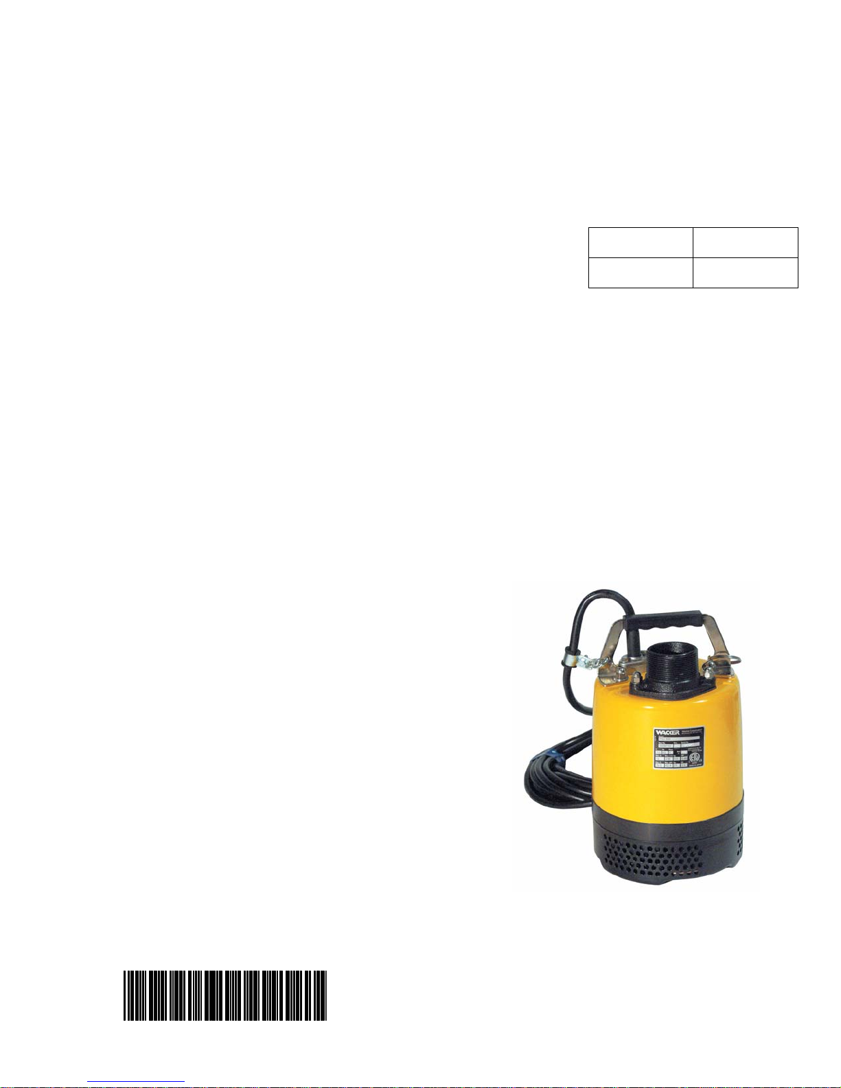
Pump
PS 2 500
PS 2 750
PSA 2 500
OPERATOR’S MANUAL
0154625EN
Page 2

Page 3

PS 2 500/PS 2 750/PSA 2 500 Table of Contents
1. Foreword 4
2. Safety Information 5
2.1 Operating and Electrical Safety ............................................................ 6
2.2 Information Labels ................................................................................ 6
3. Technical Data 7
3.1 Standard Specifications ........................................................................ 7
3.2 Operating Specifications (50 Hz) .......................................................... 8
3.3 Dimensions ........................................................................................... 9
4. Operation 10
4.1 Names of Parts ................................................................................... 10
4.2 Prior to operation ................................................................................ 11
4.3 Installation .......................................................................................... 11
4.4 Electrical Wiring .................................................................................. 15
4.5 Electrical Circuit Diagrams ................................................................. 17
4.6 Operation ............................................................................................ 20
5. Maintenance 25
5.1 Periodic Maintenance Table ............................................................... 25
5.2 Maintenance and Inspection .............................................................. 26
5.3 Disassembly/Reassembly .................................................................. 28
5.4 Disassembly ....................................................................................... 29
5.5 Reassembly ........................................................................................ 30
5.6 Troubleshooting .................................................................................. 31
wc_bo0154625003enTOC.fm 3
Page 4

Foreword
1. Foreword
This manual provides information and procedures to safely operate
and maintain this Wacker model. For your own safety and protection
from injury, carefully read, understand and observe the safety
instructions described in this manual.
Keep this manual or a copy of it with the machine. If you lose this
manual or need an additional copy, please contact Wacker
Corporation. This machine is built with user safety in mind; however,
it can present hazards if improperly operated and serviced. Follow
operating instructions carefully! If you have questions about operating
or servicing this equipment, please contact Wacker Corporation.
The information contained in this manual was based on machines in
production at the time of publication. Wacker Corporation reserves the
right to change any portion of this information without notice.
All rights, especially copying and distribution rights, are reserved.
Copyright 2007 by Wacker Corporation.
No part of this publication may be reproduced in any form or by any
means, electronic or mechanical, including photocopying, without
express written permission from Wacker Corporation.
Any type of reproduction or distribution not authorized by Wacker
Corporation represents an infringement of valid copyrights and will be
prosecuted. We expressly reserve the right to make technical
modifications, even without due notice, which aim at improving our
machines or their safety standards.
4
Page 5
PS 2 500 / PS 2 750 / PSA 2 500 Safety Information
2. Safety Information
This manual contains DANGER, WARNING, CAUTION, NOTICE and
NOTE callouts which must be followed to reduce the possibility of
personal injury, damage to the equipment, or improper service.
This is the safety alert symbol. It is used to alert you to potential
personal injury hazards. Obey all safety messages that follow this
symbol to avoid possible injury or death.
DANGER indicates a hazardous situation which, if not avoided, will
result in death or serious injury.
DANGER
WARNING
CAUTION
WARNING indicates a hazardous situation which, if not avoided, could
result in death or serious injury.
CAUTION indicates a hazardous situation which, if not avoided, could
result in minor or moderate injury.
NOTICE: Used without the safety alert symbol, NOTICE indicates a
hazardous situation which, if not avoided, could result in property
damage.
Note: Contains additional information important to a procedure.
wc_si000040gb.fm 5
Page 6
Safety Information PS 2 500 / PS 2 750 / PSA 2 500
2.1 Operating and Electrical Safety
To reduce risk of electric shock, connect only to a properly grounded,
WARNING
grounding-type receptacle.
Risk of electric shock - This pump has not been investigated for use in
swimming pool areas.
An acceptable motor-control switch shall be provided at the time of
installation according to local codes and regulations.
To reduce risk of electric shock, see instruction manual for proper
installation.
CAUTION: This pump may automatically restart. Prior to working on
the pump or control panel all supply circuits must be disconnected.
CAUTION: Risk of shock - Do not remove cord and strain relief.
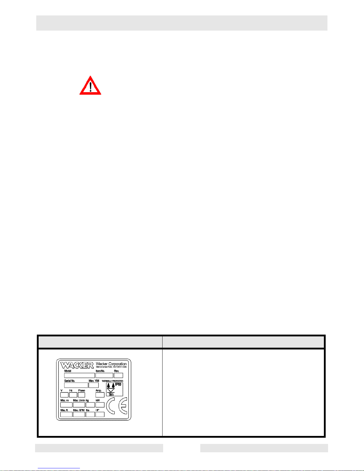
2.2 Information Labels
Label Meaning
MADE IN TAIWAN
wc_si000040gb.fm 6
A nameplate listing the model number, item number, revision number, and serial number is
attached to each unit. Please record the information found on this plate so it will be available
should the nameplate become lost or damaged.
When ordering parts or requesting service information, you will always be asked to specify the
model number, item number, revision number,
and serial number of the unit.
Page 7
PS 2 500 / PS 2 750 / PSA 2 500 Technical Data
3. Technical Data
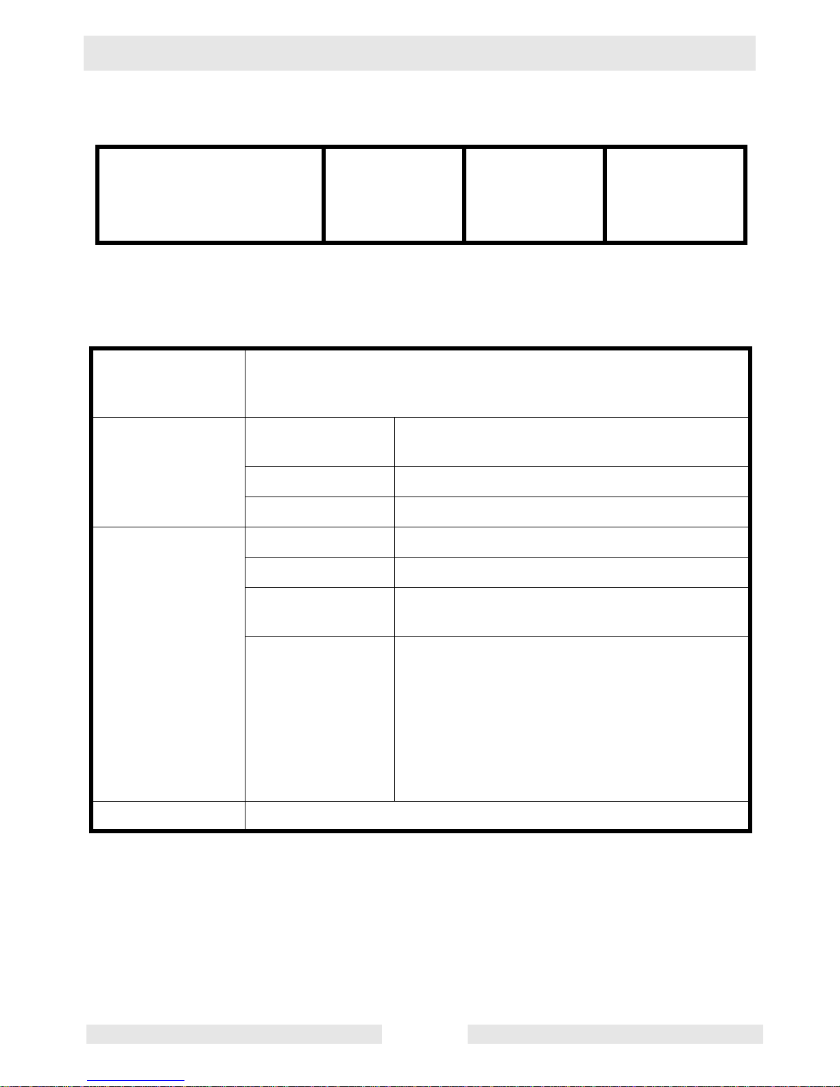
Machines discussed in this manual:
Part No. PS2 500
0008793, 0008794
0008795, 0008796
0009176, 0009177
0009178, 0620124
PSA 2 500
0008787, 0008790
0008791, 0008792
0009179, 0009180
0009181, 0620125
PS2 750
0008797, 0008798
0008799, 0008800
0009182, 0009183
0009184, 0620126
3.1 Standard Specifications
Applicable Liquids,
Consistency and
Temperature
Pump Impeller Semi-Vortex Type: (PS 2 500, PSA 2 500)
Shaft Seal Double Mechanical Seal
Bearing Shielded Ball Bearing
Motor Specification Dry Submersible Induction Motor (2-Pole)
Rain Water, Fountain Water, Ground Water,
Sand-Carrying Water
0–40°C (32–104°F)
Open Type: (PS 2 750)
Insulation Class E
Protection System Miniature Protector: (PS 2 500, PSA 2 500)
Circle Thermal Protector: (PS 2 750)
Lubricant SAE 10W/20W
Such as:
–Turbine Oil ISO VG #32
–Shell Victrolia Oil #27
–British Pet Energol THB #32
–Gulf Paramount #32
–Tellus #T22 Shell Oil
–Shell Turbo T32
Connection Hose Coupling (Barb, BSP, QD–2")
wc_td000040gb.fm 7
Page 8
Technical Data PS 2 500 / PS 2 750 / PSA 2 500
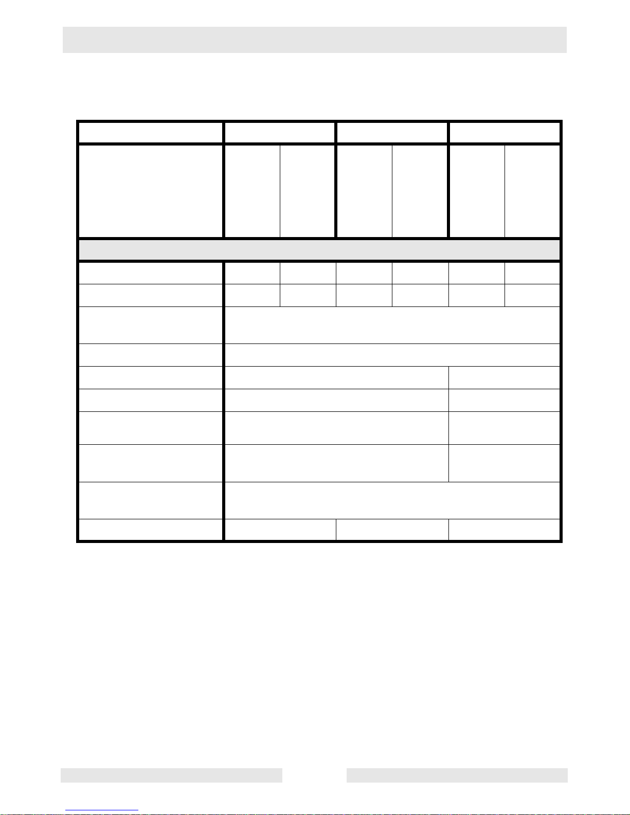
3.2 Operating Specifications (50 Hz)
Part No. PS 2 500 PSA 2 500 PS 2 750
Electric Power
Rated Current
Starting
Method
Discharge
Output
Max. Head
Max. Capacity
0008793
0008794
0008795
0008796
0009176
0009177
0620124
0009178
0008787
0008790
0008791
0008792
0009179
0009180
0620125
0009181
0008797
0008798
0008799
0008800
0009182
0009183
0620126
0009184
Pump
V/Ph/Hz 230/1/50 110/1/50 230/1/50 110/1/50 230/1/50 110/1/50
A
2.9 6.2 2.9 6.2 6.3 13.9
Capacitor-Run
mm (in.)
kW (Hp)
m (ft.)
L/min
(GPM)
0.48 (2/3) 0.75 (1)
11 (36) 16 (52.2)
220 (58) 276 (73)
50 (2)
Max. Pressure
Soild Size
mm (in.)
kg/cm
(psi)
2
1.19 (17) 1.83 (26)
6 (0.2)
Capacity
Weight*
* The weight (mass) given above is the operating weight of the pump itself, not including the cable
assembly.
Kg (lbs.)
9.5 (21) 10.0 (22) 16.0 (35)
wc_td000040gb.fm 8
Page 9
PS 2 500 / PS 2 750 / PSA 2 500 Technical Data
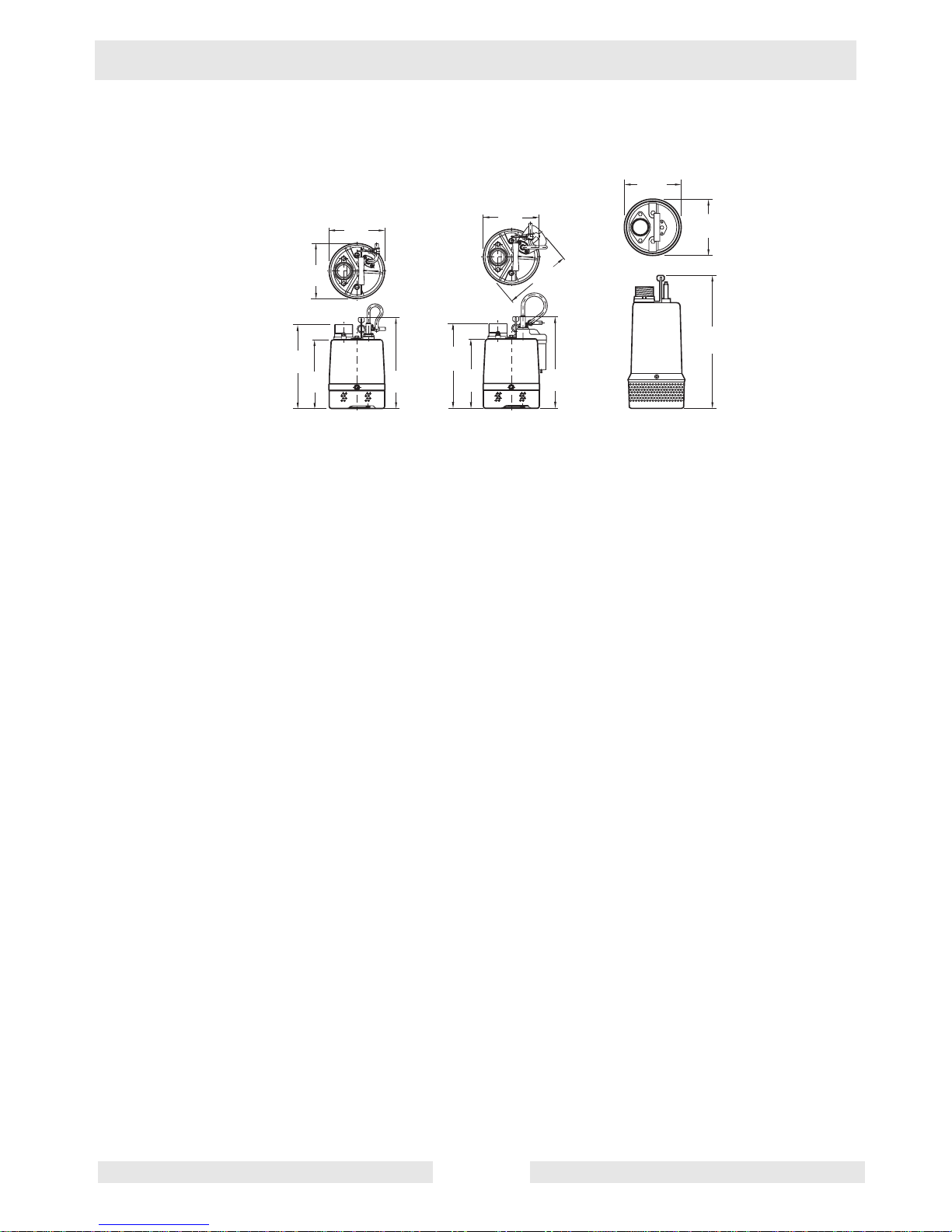
3.3 Dimensions
mm (in.)
185
(7.3)
185
(7.3)
185
(7.3)
185
(7.3)
200
(11)
185
(7.3)
229
(9)
PS 2 500
305
(12)
200
(11)
229
(9)
222
(8.8)
PSA 2 500
305
(12)
PS 2 750
414
(16.3)
wc_td000040gb.fm 9
Page 10

Operation PS 2 500 / PS 2 750 / PSA 2 500
4. Operation
4.1 Names of Parts
See Graphic: wc_gr001185
1
2
3
4
5
6
7
8
9
10
11
12
13
14
wc_gr001185
Ref. Description Ref. Description
1. Lifting Handle 8. Seal-mechanical
2. Coupling 9. Lubricant
3. Oil Lifter 10. Seal-dust
4. Oil Plug 11. Sleeve
5. Cover-suction 12. Housing-oil
6. Strainer 13. Wear Ring
7. Cable Assembly 14. Impeller
wc_tx000121gb.fm 10
Page 11
PS 2 500 / PS 2 750 / PSA 2 500 Operation
4.2 Prior to operation
When the pump is delivered, first perform the following checks:
• Inspection
While unpacking, inspect the product for damage during shipment, and
make sure all bolts and nuts are tightened properly.
• Specification check
Check the model number to make sure it is the product that was
ordered. Be certain it is the correct voltage and frequency.
Note: If there is any problem with the product as shipped, contact your
nearest dealer or Wacker representative at once.
• Product specifications
Do not operate this product under any conditions other than those for
which it is specified. Failure to observe this precaution can lead to
CAUTION
electrical shock, current leakage, fire, water leakage or other
problems.
4.3 Installation
If the pump is used for outdoor fountains, garden ponds and similar
places, or to drain a swimming pool, the pump must be supplied by an
isolating transformer or connected to a Residual Current Device (RCD)
WARNING
with a residual operating current not exceeding 30 mA.
The pump must not be used when people are in the water.
Leakage of pump lubricants may cause pollution of water.
Proper plug must be provided according to local codes and standards.
Refer to wiring diagram.
DO NOT use this pump in liquids other than water, such as oil, salt
water, or organic solvents.
Use with a power supply voltage within ±5% of the rated voltage.
DO NOT use in water temperatures outside the range of 0–40°C (32–
104°F) which can lead to failure, electrical leakage or shock.
DO NOT use in the vicinity of explosive or flammable materials.
Use only in fully assembled state.
Note: Consult your local dealer or Wacker representative before using
with any liquids other than those indicated in this document.
wc_tx000121gb.fm 11
Page 12
Operation PS 2 500 / PS 2 750 / PSA 2 500
Preparing for Installation
Before installing the pump at a work site, you will need to have the
following tools and instruments ready:
• Insulation resistance tester (megohmmeter)
• AC voltmeter
• AC ammeter (clamp-on type)
• Bolt and nut tighteners
• Power supply connection tools (screwdriver or box wrench)
Note: Please also read the instructions that come with each of the test
instruments.
Checks to Make Before Installation
When a grounded plug is used:
Use the megohmmeter to measure the insulation resistance between
the cable assembly prongs and ground.
When connection leads are used:
With the megohmmeter, measure the insulation resistance between
each core lead and the ground lead.
Reference insulation resistance: 20MW or greater
Note: The reference insulation resistance (20MW or greater) is the
value when the pump is new or has been repaired. For the reference
value after installation, see Maintenance and Inspection.
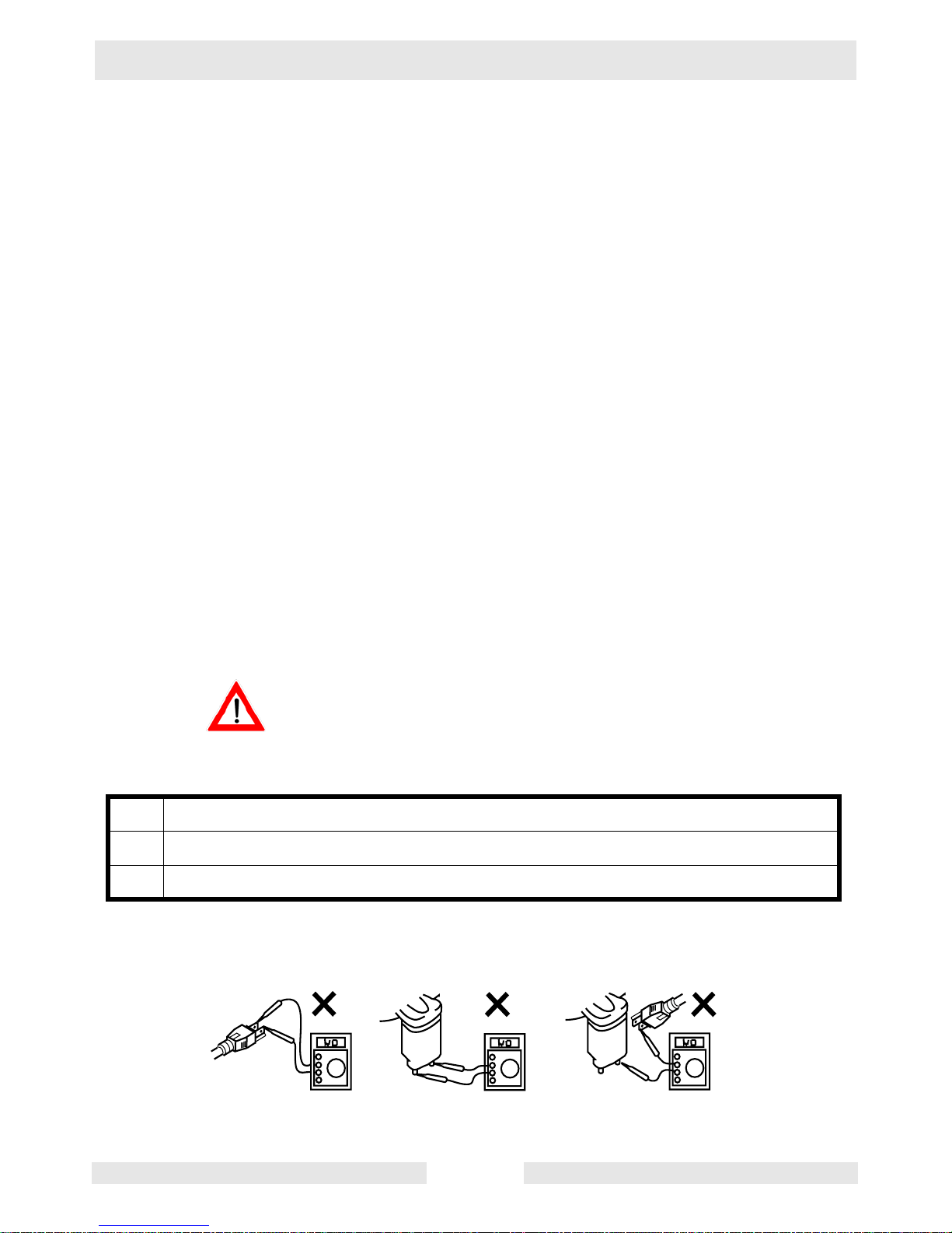
DO NOT measure the insulation resistance with insulation resistance
tester for the following parts. It will cause damage (Model PSA 2 500).
CAUTION
Improper ways to measure insulation resistance
1. Between the plug prongs.
2. Between the electrodes on the level relay unit.
3. Between the electrodes on the level relay unit and the plug prongs.
See Graphic: wc_gr000258
1
2
3
wc_tx000121gb.fm 12
wc_gr000258
Page 13

PS 2 500 / PS 2 750 / PSA 2 500 Operation
Precautions During Installation
Do not under any circumstances install or move the pump by
suspending it from the cable assembly. The cable may be damaged,
WARNING
CAUTION
4.3.1 This pump series is offered with a variety of discharge fittings. Follow
causing electrical leakage, shock, or fire.
When installing the pump, pay close attention to its center of gravity
and weight. If it is not lowered into place correctly, it may fall and be
damaged or cause injury.
When transporting the pump by hand, be sure to employ manpower
commensurate with the weight of the pump. To avoid back injury when
lifting the pump, bend the knees to pick it up rather than bending your
back only.
procedures noted below to assure a proper discharge connection.
Threaded Discharge Fitting (BSP) –
Tighten hose coupling or discharge pipe securely and with proper
gaskets.
Quick Disconnect Coupling (QD) –
Assure coupling is tightened securely to pump discharge fitting and
companion coupling is securely fastened with proper gaskets.
Barbed Discharge Fitting (Barb) –
Place hose clamp over hose and push hose to the base of the
discharge fitting. Tighten the hose clamp to secure the hose in place.
4.3.2 Avoid dropping the pump or other strong impact. Lift the pump by
holding it firmly with the hands or by attaching a rope or chain to the
handle.
Note: On cable assembly handling, see Electrical Wiring.
4.3.3 Install the pump in a location with sufficient water level, where water
collects readily.
Note: See “Operating Water Level” for the water level necessary for
operation. The discharge end of the hose should be located higher
than the water surface. If the end of the hose is submerged, water may
flow back to the pump when the pump is stopped; and if the hose end
is lower than the water surface, water may overflow when the pump is
turned off.
4.3.4 The hose should be run as straight as possible, since excessive
bending will hinder the water flow, preventing sufficient lift, and can
even cause the hose to become clogged with earth. If the hose is
crimped near the pump, air can become trapped in the pump and
cause idle running.
wc_tx000121gb.fm 13
Page 14
Operation PS 2 500 / PS 2 750 / PSA 2 500
If large quantities of earth are sucked up, damage resulting from
friction in the pump can lead to electrical leakage and shock.
CAUTION
4.3.5 Use the pump in the upright position. To prevent the pump from
becoming submerged in mud, mount it on a block or other firm base if
necessary.
4.3.6 If used in a permanent installation, where the pump is not readily
accessible after installation, please contact Wacker for a duplicate
nameplate to be installed at the wellhead or on the control box so that
it will be readily visible.
DO NOT lift or hang the pump by the level relay unit (1). It will lead to
damage and may cause leakage, electric shock, and fire (Model PSA
CAUTION
See Graphic: wc_gr000259
2 500).
1
wc_gr000259
wc_tx000121gb.fm 14
Page 15

PS 2 500 / PS 2 750 / PSA 2 500 Operation
4.4 Electrical Wiring
Performing electrical wiring
Electrical wiring should be performed by a qualified person in accord
with all applicable regulations. Failure to observe this precaution not
WARNING
WARNING
only risks breaking the law but is extremely dangerous.
Incorrect wiring can lead to current leakage, electrical shock or fire.
ALWAYS make sure the pump is equipped with the specified overload
protectors and fuses or breakers, so as to prevent electrical shock from
a current leak or pump malfunction.
Operate within the capacity of the power supply and wiring.
Grounding
DO NOT use the pump without first grounding it properly. Failure to
ground it can lead to electrical shock from a current leak or pump
malfunction.
CAUTION
WARNING
CAUTION
DO NOT attach the grounding wire to a gas pipe, water pipe, lightning
arrestor or telephone grounding wire. Improper grounding can result in
electrical shock.
Connecting the power supply
Before connecting leads to the terminal strip, make certain the power
supply is turned off (circuit breaker, etc.), to avoid electrical shock,
shorting, or unexpected starting of the pump, leading to injury.
Before inserting the power supply plug, make certain the power supply
is turned off (circuit breaker, etc.), to avoid electrical shock, shorting,
or unexpected starting of the pump, leading to injury.
Do not use the pump with the cable assembly or plug connected
loosely, which can result in electric shock, shorting, or fire.
Draw power from a dedicated power outlet rated at 15 A or above.
Sharing the outlet with other equipment may cause overheating at the
branch outlet and could result in fire.
NOTICE: Be sure to use a dedicated power supply with a ground
leakage circuit breaker.
Grounded Plug –
Connect only to receptacle of proper voltage and current rating
matching that of the plug provided with the cable assembly.
wc_tx000121gb.fm 15
Page 16

Operation PS 2 500 / PS 2 750 / PSA 2 500
Without Plug –
Tighten the ends of the cable assembly securely against the terminal
board. If installation of grounded plug is required, use only properly
rated and approved CEE plug and secure ends of the cable assembly
securely to power and ground terminals in accordance with plug
manufacturer’s instructions.
See Graphic: wc_gr000309
CAUTION
L1
L2
G
Br
G/Y
L
wc_gr000309
Cable Assembly
If it is necessary to extend the cable assembly, use a core size equal
to or larger than the original. This is necessary not only for avoiding a
performance drop, but to prevent cable overheating which can result in
fire, electrical leakage or electrical shock.
If a cable with cut insulation or other damage is submerged in the
water, there is a danger of damage to the pump, electrical leakage,
electrical shock, or fire.
Be careful not to let the cable assembly be cut or become twisted. This
may result in damage to the pump, electrical leakage, electrical shock,
or fire.
If it is necessary to submerge the connection wires of the cable
assembly in water, first seal the wires completely in a molded
protective sleeve, to prevent electrical leakage, electrical shock, or fire.
DO NOT allow the cable assembly wires or power supply plug to
become wet.
Make sure the cable does not become excessively bent or twisted, and
does not rub against a structure in a way that might damage it.
If used in a deep-well installation, the cable assembly should be
secured every twenty feet.
wc_tx000121gb.fm 16
Page 17

PS 2 500 / PS 2 750 / PSA 2 500 Operation
4.5 Electrical Circuit Diagrams
See Graphic: wc_gr001261, wc_gr001259, wc_gr001260
Br
L
G/Y
6
R
B
W
2
5
G/Y
4
1
3
wc_gr001261
PS 2 500 POWER SOURCE SINGLE PHASE
Ref. Description Ref. Description
1. Capacitor 4. Protector
2. Main Coil 5. Frame Grounding
L
3. Auxiliary Coil 6. Ground
Wire Colors
B Black V Violet Or Orange
G Green W White Pr Purple
L Blue Y Yellow Sh Shield
P Pink Br Brown LL Light Blue
R Red Cl Clear G/Y Green/Yellow
T Tan Gr Gray
wc_tx000121gb.fm 17
Page 18

Operation PS 2 500 / PS 2 750 / PSA 2 500
1
3
R
4
B
6
Br
L
B
W
2
W
9
5
W
G/Y
G/Y
10
8
PSA 2 500 POWER SOURCE SINGLE PHASE
Ref. Description Ref. Description
1. Level Relay Unit 6. Main Coil
L
7
wc_gr001259
2. Transformer 7. Auxiliary Coil
3. Electrode 8. Miniature Protector
4. Capacitor 9. Frame Grounding
5. Triac 10. Ground
Wire Colors
B Black V Violet Or Orange
G Green W White Pr Purple
L Blue Y Yellow Sh Shield
P Pink Br Brown LL Light Blue
R Red Cl Clear G/Y Green/Yellow
T Tan Gr Gray
wc_tx000121gb.fm 18
Page 19

PS 2 500 / PS 2 750 / PSA 2 500 Operation
_
Br
1
3
R
2
1
R
R
2
3
L
W
4
5
7
G/Y
L
L
G/Y
8
6
wc
PS 2 750 POWER SOURCE SINGLE PHASE
Ref. Description Ref. Description
1. Circle Thermal Protector 5. Centrifugal Switch
2. Auxiliary Coil 6. Capacitor
3. Heater 7. Frame Grounding
gr001260
4. Main Coil 8. Ground
Wire Colors
B Black V Violet Or Orange
G Green W White Pr Purple
L Blue Y Yellow Sh Shield
P Pink Br Brown LL Light Blue
R Red Cl Clear G/Y Green/Yellow
T Tan Gr Gray
If connected to a circuit protected by a fuse, use a time-delay fuse with
this pump.
CAUTION
wc_tx000121gb.fm 19
Page 20

Operation PS 2 500 / PS 2 750 / PSA 2 500
4.6 Operation
Before starting
4.6.1 Make sure once again that the product is of the correct voltage and
frequency rating.
NOTICE: Using the product at other than rated voltage and frequency
will not only lower its performance but may damage the product.
Note: Confirm the rated voltage and frequency on the model
nameplate.
4.6.2 Confirm the wiring, supply voltage, circuit breaker capacity, and motor
insulation resistance.
Reference insulation resistance = 20 MΩ or greater.
Note: The reference insulation resistance (20 MΩ or greater) is the
value when the pump is new or has been repaired. For the reference
value after installation see Maintenance and Inspection.
4.6.3 The setting on the circuit breaker or other overload protector should be
made in accord with the rated current of the pump.
Note: See Standard Specifications for the rated current of the pump.
4.6.4 When powering the pump with a generator, be certain the generator is
sized to supply the required power for the pump and any other
equipment powered by the generator.
Non-Automatic Models (PS 2 500, PS 2 750)
Test Operation
NEVER operate the pump while it is suspended in the air. The recoil
may result in injury or other major accident.
WARNING
NEVER start the pump when people are standing next to it. A current
leak can result in electrical shock.
WARNING
Run the pump for a short time (3–10 minutes) and confirm the
following:
• Using an ammeter (clamp-on type), measure the operating
current at the L1 and L2 phase wires on the terminal.
COUNTERMEASURE: If the operating current exceeds the rated
value, pump motor overload may be a cause. Make sure the pump has
been installed under proper conditions as described in Installation.
• Using an AC voltmeter (tester), measure voltage at the terminals.
Supply voltage tolerance: within ±5% of rated voltage.
wc_tx000121gb.fm 20
Page 21

PS 2 500 / PS 2 750 / PSA 2 500 Operation
COUNTERMEASURE: If the supply voltage is outside the tolerance,
possible causes are the power supply capacity or an inadequate
extension cable. Look again at Electrical Wiring and make sure the
conditions are proper.
In case of very excessive vibration, unusual noise or odor, turn off the
power immediately and consult with your nearest dealer or Wacker
CAUTION
WARNING
representative. Continuing to operate the pump under abnormal
conditions may result in electrical shock, fire, or current leakage.
Operation
Make sure no extraneous objects such as pins, nails or other metal
objects are sucked into the pump. These can damage the pump or
cause it to malfunction, and can result in electrical shock or electrical
leakage.
When the pump is not used for an extended period, be sure to turn off
the power (circuit breaker, etc.). Deterioration of the insulation may
lead to electrical leakage, electrical shock, or fire.
In case of a power outage, turn off the power to the pump to avoid
having it start unexpectedly when the power is restored, presenting
serious danger to people in the vicinity.
CAUTION
CAUTION
The pump may become hot during operation. Do not touch an
operating pump. Allow the pump to cool before handling.
Pay careful attention to the water level while the pump is operating. Dry
operation may cause the pump to malfunction.
Note: See section Operating water level, for the water level necessary
for operation.
If the protection system operates due to an overload or malfunction,
causing the pump to stop, first investigate and remove the cause
before restarting.
Operating water level
Do not operate the pump below the C.W.L. (Continuous running Water
Level) indicated below. Failure to observe this condition may result in
damage to the pump, current leakage or electrical shock.
wc_tx000121gb.fm 21
Page 22

Operation PS 2 500 / PS 2 750 / PSA 2 500
See Graphic: wc_gr001225
a
b
C.W.L
115 mm (4-1/2")
PS 2 500, PS 2 750
Pump Model C.W.L.
PS 2 500 50mm (2”)
PS 2 750 100mm (4”)
PSA 2 500
wc_gr001225
Operating Water Level (PS 2 500, PS 2 750).
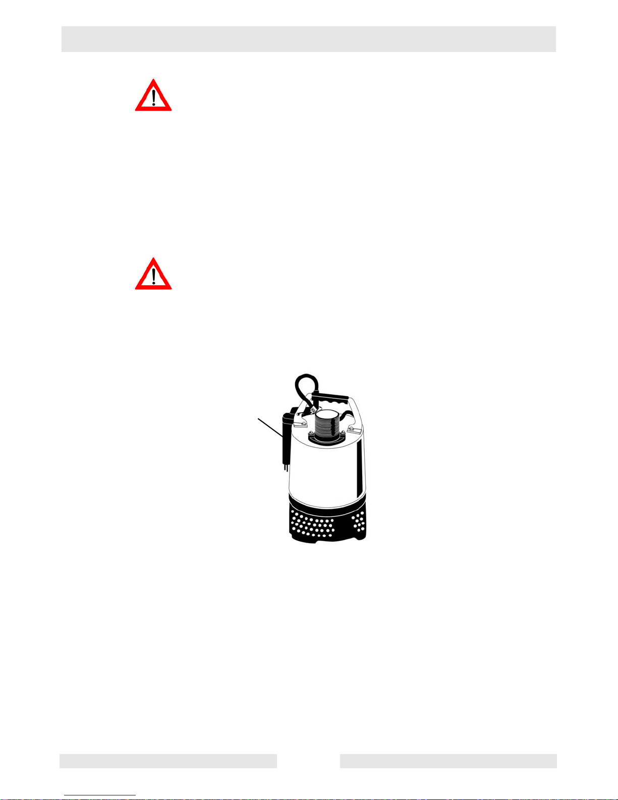
Operating water level (PSA 2 500 only)
Starting the Pump:
This pump starts when water reaches the electrodes on the level relay
unit, conducting current between them.
Note: The necessary water level to operate the pump is 115 mm
(4-½") from the bottom of the pump. To force start the pump for trial
operation, short-circuit the electrodes (a) with a screwdriver (b) as
illustrated. Please keep items that may clog the pump (such as wires,
nails, cords, etc.) away from it.
Motor Protection System (Motor Protector)
Circle Thermal protector (PS 2 750)
Miniature Protector (PS 2 500, PSA 2 500)
wc_tx000121gb.fm 22
Page 23

PS 2 500 / PS 2 750 / PSA 2 500 Operation
The pump has a built-in motor protection system. If an excessive
current is detected (PS 2 750) or the motor overheats, for reasons
such as the following, the pump will automatically stop operating
regardless of the water level, to protect the motor:
• Change in supply voltage polarity
• Overload
• Open-phase operation or operation under constraint
Note: Always determine the cause of th e problem and resolve it before
resuming operation. Simply repeating cycles of stopping and restarting
will end up damaging the pump. Do not continue operation at very low
lift, low water level, or while the strainer stand is clogged with debris.
Not only will performance suffer, but also such conditions may cause
noise, heavy vibration, and malfunctioning.
Operating Cycle of Automatic Type (PSA 2 500) .
Stage Level Relay Unit Pump Water Level
1 When electrodes (b) of level relay units (a)
submerge under water, the resulting electric current causes the pump to operate.
(Electrodes sensing the electricity)
2 When the water level goes below the
height of the electrodes, a timer is activated. The pump keeps operating. (No
electric current –>Timer activates.)
3 The pump keeps operating for approxi-
mately one minute. (The pump resumes
the operation if the electrodes contact the
water again within one minute.)
4 The pump stops one minute later. (The
pump may not stop operating for a longer
period of time.)
5 When the water level rises again and the
electrodes touch the water, the pump
starts operating again. (Electrodes sensing the electricity)
Operation
starts
(drainage)
Operation
remains
(drainage)
Operation
remains
(drainage)
Operation
stops
Operation
starts again
(drainage)
Falls
Falls
Falls
Rises
Falls
wc_tx000121gb.fm 23
Page 24

Operation PS 2 500 / PS 2 750 / PSA 2 500
See Graphic: wc_gr000312
a
a
1
b
b
2
3
4
wc_tx000121gb.fm 24
5
wc_gr000312
Page 25

PS 2 500 / PS 2 750 / PSA 2 500 Maintenance
5. Maintenance
5.1 Periodic Maintenance Table
Pump
Measure insulation resistance.
Reference insulation resistance =
1MW or greater. (1)
Measure operating current.
Compare with rated current.
Measure supply voltage.
Compare with allowable range (within ±5% of rated
voltage).
Pump inspection.
A noticeable drop in performance may indicate
wear in the impeller, etc., or else clogging of the
strainer, etc. Remove the clogged debris and
replace any worn parts.
Lubricant inspection.
Change lubricant.
Weekly Monthly Every
1000
hrs.
Every
2000
hrs.
Designated lubricant: SAE 10W/20W. (2)
Change mechanical seal. (3)
Overhaul.
This should be carried out even if there are no problems with the pump. The frequency depends on
how continuously the pump is in use. (4)
(1) If the insulation resistance has become noticeably lower than the previous inspection, an inspec-
tion of the motor will be necessary.
(2) See Lubricant Inspection and Lubricant Change in this section.
(3) Specialized know-how is required for inspecting and replacing the mechanical seal. Consult with
your nearest dealer or Wacker representative.
(4) Consult with your nearest dealer or Wacker representative regarding overhauls.
wc_tx000114gb.fm 25
Page 26

Maintenance PS 2 500 / PS 2 750 / PSA 2 500
5.2 Maintenance and Inspection
Regular maintenance and inspections are a necessity for continued
efficient functioning of the pump. If any abnormal conditions are
noticed, refer to Troubleshooting section and take corrective measures
immediately. It is recommended that a spare pump be kept ready in
case of any problems.
Prior to inspecting
Before inspecting the pump, make certain the power supply (circuit
breaker, etc.) is turned off. Then, unplug the cable assembly from the
WARNING
5.2.1 Washing the pump
5.2.2 Inspecting the pump exterior
receptacle or detach it from the terminals. Failure to follow this
precaution may result in a serious accident from electrical shock or
unexpected starting of the pump motor.
Remove accumulated matter from the surface of the pump and wash
it with clean water. Take special care to remove any debris from the
impeller.
Look for any peeling or chipped paint, and make sure the nuts and
bolts are fastened tightly. Any cracks in the surface should be repaired
by cleaning that area, drying it and then applying a touch-up coating.
Note: Touch-up paint is not supplied. Note that some kinds of damage
or looseness may require that the unit be disassembled for repairs.
Please consult with your nearest dealer or Wacker representative.
Storage
When the pump is out of use for an extended period, wash it and dry it
thoroughly, then store it indoors.
Note: Always run a test operation before putting the pump back into
service.
If the pump is left in the water, it should be run a minimum of once a
week.
Lubricant Inspection and Lubricant Change
• Inspecting Lubricant
Remove the Oil Plug and tilt the pump to drain a small amount of
lubricant. If the lubricant is milky white or has water mixed in with it, the
mechanical seal may be faulty. In this case the pump will need to be
disassembled and repaired.
• Replacing Lubricant
Remove the Oil Plug and drain all the lubricant, then replace it with the
specified amount.
wc_tx000114gb.fm 26
Page 27

PS 2 500 / PS 2 750 / PSA 2 500 Maintenance
Note: Worn lubricant and other waste products should be disposed of
by a qualified agent, in accord with applicable laws. The oil plug gasket
should be replaced each time the lubricant is inspected or changed.
See Graphic: wc_gr001204
1
2
3
4
wc_gr001204
Ref. Description Ref. Description
1. Oil Inlet 3. Oil Plug
2. Gasket 4. Allen Wrench
Pump Model Lubricant Capacity
PS 2 400 160 ml (5.4 fl. oz.)
PS 2 500, PSA 2 500 155 ml (5.2 fl. oz.)
PS 2 750 210 ml (7.1 fl. oz.)
Replacement Parts
The table lists the parts that need to be replaced periodically. Replace
these using the recommended frequency as a guideline.
Part Replacement Frequency
Seal - Mechanical When lubricant in oil compartment becomes milky.
Lubricant (SAE 10W/20W) Every 2,000 hours or 12 months, whichever comes first.
Gasket Each time pump is disassembled or inspected.
Seal-dust When ring is worn, and each time pump is disassem-
Sleeve When it becomes worn.
wc_tx000114gb.fm 27
bled or inspected.
Page 28

Maintenance PS 2 500 / PS 2 750 / PSA 2 500
5.3 Disassembly/Reassembly
Before disassembling the pump, make certain the power supply (circuit
breaker, etc.) is turned off. Then, unplug the cable assembly from the
WARNING
receptacle or detach it from the terminals. To avoid electrical shock,
DO NOT work with wet hands.
NEVER check the operation of any parts (impeller rotation, etc.) by
turning on the power while the unit is partially assembled. Failure to
observe these precautions may result in a serious accident.
DO NOT disassemble or repair any parts other than those designated
here. If repairs are necessary in any other than the designated parts,
consult with your nearest dealer or Wacker representative. Improper
repairs can result in electrical leakage, electrical shock, fire, or water
leaks.
After reassembly, ALWAYS perform a test operation before resuming
use of the pump. Improper assembly will cause the pump to
malfunction, resulting in electric shock or water leaks.
The procedure for disassembly and reassembly is shown here to the
extent necessary for impeller replacement. A specialized environment
and facilities are necessary for work on the mechanical seal and the
motor parts. Contact your nearest dealer or Wacker representative in
the event such repairs are necessary.
wc_tx000114gb.fm 28
Page 29

PS 2 500 / PS 2 750 / PSA 2 500 Maintenance
5.4 Disassembly
See Graphic: wc_gr001206
5.4.1 Removing the strainer, suction cover, and volute:
Remove the bolts (1) under the strainer (2), then remove the strainer,
suction cover (3), and volute (4).
5.4.2 Removing the Impeller:
With a box wrench or other tool, remove the acorn nut (6), lockwasher
(7) and washer (8), then remove the impeller (9), sleeve (10) and dust
seal (11) from the shaft.
5.4.3 Removing the wear ring:
Remove the wear ring (12) from the volute.
A worn impeller may have sharp edges that can cause injury, and
should be handled with care.
WARNING
4
3
Note: The exploded view shown is for model PS 2 500. Other models
may differ slightly in shape and structure.
11
10
12
2
1
wc_tx000114gb.fm 29
9
8
7
6
wc_gr001206
Page 30

Maintenance PS 2 500 / PS 2 750 / PSA 2 500
5.5 Reassembly
See Graphic: wc_gr001206, wc_gr001205
5.5.1 Mount the dust seal (11) onto the outside of the sleeve (10) as shown
in the drawing. When doing so, do not apply oil or other lubrication to
the surface where the dust seal contacts the sleeve (a).
5.5.2 When replacing the wear ring (12), make sure the front and back are
oriented correctly. The side with the protrusions around the edge
should face the volute (4). Press the wear ring firmly onto the surface.
5.5.3 Replace the dust seal and sleeve as one piece.
5.5.4 Align the impeller keyway with the rotor shaft keyway and push the
impeller (9) onto the rotor shaft. Secure the impeller on the shaft with
the washer (8), lockwasher (7), and acorn nut (6). While keeping the
impeller and shaft from rotating, tighten the acorn nut.
5.5.5 Position volute (4) flush with oil housing. Assemble suction cover (3)
and strainer (2) and secure the assembly with the three bolts (1).
11
a
10
wc_gr001205
wc_tx000114gb.fm 30
Page 31

PS 2 500 / PS 2 750 / PSA 2 500 Maintenance
5.6 Troubleshooting
Before ordering repairs, carefully read through this manual, then
repeat the inspection. If the problem remains, contact your nearest
dealer or Wacker representative.
ALWAYS turn off the power before inspecting the pump. Failure to
WARNING
observe this precaution can result in serious accident.
Problem / Symptom
Pump will not start
Pump stops soon after start-
ing (Motor protector operates)
Reason / Remedy
• Power is off. Restore power.
• Cable assembly is cut or not connected properly. Repair/
replace the cable or fix the connection.
• Plug is not inserted. Connect the plug.
• Impeller is clogged. Inspect the pump and remove any
debris.
• Start float does not operate. Remove any obstruction
and check the float operation.
• Impeller is clogged. Remove debris.
• Low voltage. Provide the rated voltage, or make sure the
cable assembly extension is the proper standard.
• Wrong power frequency. Check the nameplate, and
replace the pump or the impeller.
• Extended operation with a clogged strainer. Remove
debris from the strainer.
• Faulty motor (burning, water infiltration, etc.). Repair or replace
the motor.
• Motor protection system was triggered. Identify and correct cause before re-starting.
Poor lift or discharge
capacity
Heavy vibration or noise
Pump will not stop automati-
cally
wc_tx000114gb.fm 31
• Worn out impeller or suction cover. Repair or replace the
worn parts.
• Sharply bent or clogged hose. Straighten out any sharp
bends. Enclose the pump with a screen to keep away
debris.
• Strainer clogged or buried. Remove debris from the
strainer, or place a block under the pump.
• Wrong power frequency. Check the nameplate, and
replace the pump or the impeller.
• Damaged motor shaft. Contact dealer and replace
motor.
• Something is interfering with the float operation, or the
float switch is faulty. Remove any obstacles, or replace
the switch.
Page 32

Maintenance PS 2 500 / PS 2 750 / PSA 2 500
Notes
wc_tx000114gb.fm 32
Page 33

Page 34

Page 35

Page 36

Page 37

Page 38

Page 39

Page 40

Page 41

Page 42

Page 43

Page 44

Page 45

EC DECLARATION OF CONFORMITY
CE-KONFORMITÄTSERKLÄRUNG
DECLARACIÓN DE CONFORMIDAD DE LA CE
DÉCLARATION DE CONFORMITÉ C.E.
WACKER NEUSON CORPORATION, N92 W15000 ANTHONY AVENUE, MENOMONEE FALLS, WISCONSIN USA
AUTHORIZED REPRESENTATIVE IN THE EUROPEAN UNION
BEVOLLMÄCHTIGTER VERTRETER FÜR DIE EUROPÄISCHE GEMEINSCHAFT
REPRESENTANTE AUTORIZADO EN LA UNIÓN EUROPEA
REPRÉSENTANT AGRÉÉ AUPRÈS DE L’UNION EUROPÉENNE
hereby certifies that the construction equipment specified hereunder:
bescheinigt, daß das Baugerät:
certifica que la máquina de:
construcción / atteste que le matériel :
WACKER CONSTRUCTION EQUIPMENT AG
Preußenstraße 41
80809 München
1. Category / Art / Categoría / Catégorie
Water Pump Units
Wasserpumpen
Equipos de Bomba de Agua
Groupe Motopompe à Eau
2. Type - Typ - Tipo - Type
PS2 500, PS2 750
3. Item number of equipment / Artikelnummer / Número de referencia de la máquina / Numéro de référence du matériel :
0008793, 0008794, 0008795, 0008796, 0008787, 0008790, 0008791, 0008792, 0009176, 0009178,
0009179, 0009180, 0009181, 0008797, 0008798, 0008799, 0008800, 0009182, 0009184, 0620124,
0620125, 0620126
and has been produced in accordance with the following standards:
und in Übereinstimmung mit folgenden Richtlinien hergestellt worden ist:
y ha sido fabricado en conformidad con las siguientes normas:
et a été produit conforme aux dispositions des directives européennes ci-après :
EN 60 335-2-41:96
EN 60 335-1:94 + A11:95
EMC 89/336/EEC
EN 50081-1:1992
28.07.08
Date / Datum / Fecha / Date
2008-CE-PS2-500-750_Q.fm
William Lahner Dan Domanski
Vice President of Engineering Manager, Product Engineering
WACKER NEUSON CORPORATION
Page 46

Wacker Construction Equipment AG · Preußenstraße 41 · D-80809 München · Tel.: +49-(0)89-3 54 02 - 0 · Fax: +49 - (0)89-3 54 02-3 90
Wacker Corporation · P.O. Box 9007 · Menomonee Falls, WI 53052-9007 · Tel. : (262) 255-0500 · Fax: (262) 255-0550 · Tel. : (800) 770-0957
Wacker Asia Pacific Operations · Skyline Tower, Suite 2303, 23/F · 39 Wang Kwong Road, Kowloon Bay, Hong Kong · Tel. +852 2406 60 32 · Fax: +852 2406 60 21
 Loading...