

Page 1
Operator’s Manual
5000188001
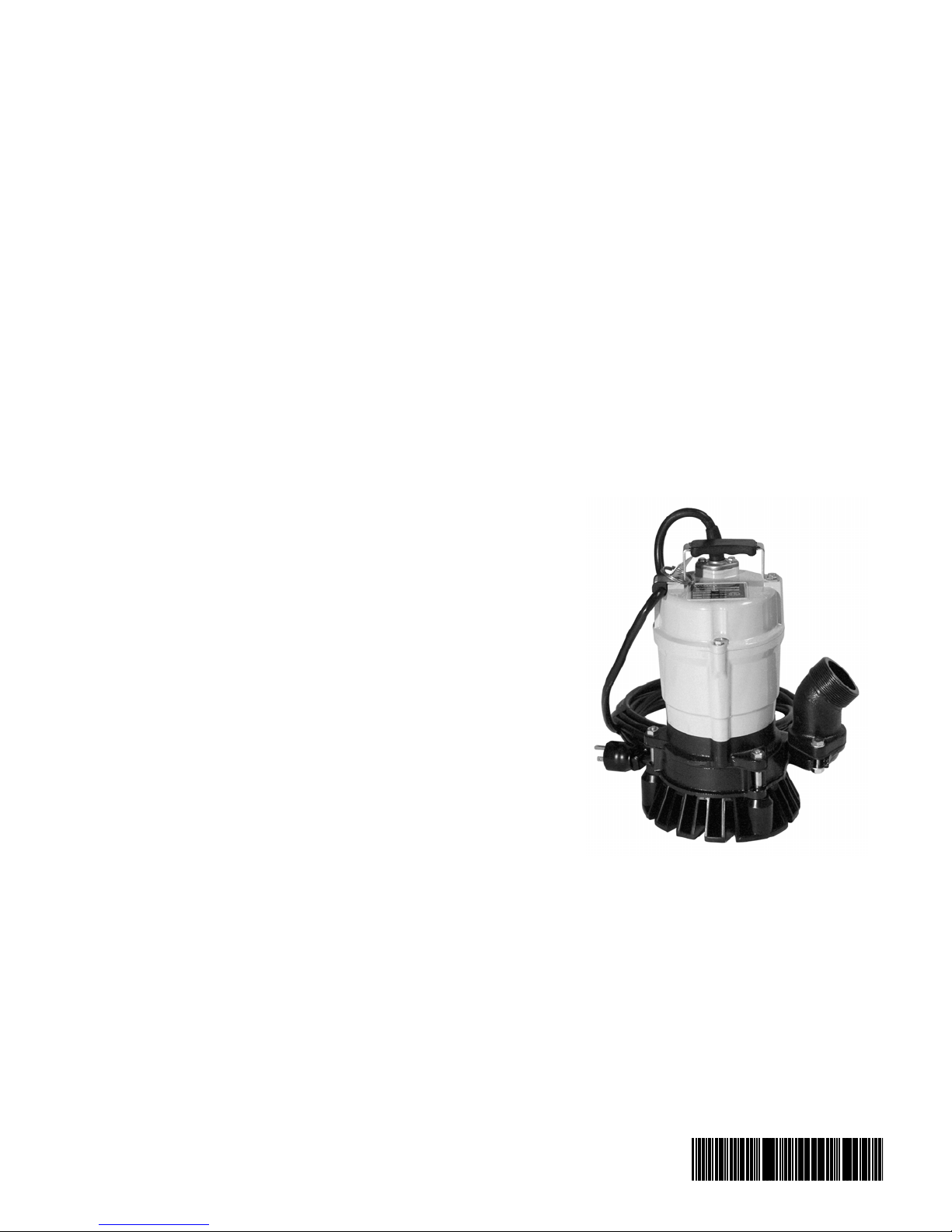
Pump
PST2-400, PSTF2-400
Type PST2-400, PSTF2-400
Document 5000188001
Date
Version 06
Language
1215
EN
Page 2

Copyright notice
© Copyright 2015 by Wacker Neuson Production Americas LLC
All rights, including copying and distribution rights, are reserved.
This publication may be photocopied by the original purchaser of the
machine. Any other type of reproduction is prohibited without express
written permission from Wacker Neuson Production Americas LLC.
Any type of reproduction or distribution not authorized by Wacker
Neuson Production Americas LLC represents an infringement of valid
copyrights. Violators will be prosecuted.
Trademarks
All trademarks referenced in this manual are the property of their
respective owners.
Manufacturer
Wacker Neuson Production Americas LLC
N92W15000 Anthony Avenue
Menomonee Falls, WI 53051 U.S.A.
Tel: (262) 255-0500 · Fax: (262) 255-0550 · Tel: (800) 770-0957
www.wackerneuson.com
Original instructions
This Operator’s Manual presents the original instructions. The original
language of this Operator’s Manual is American English.
Page 3

Foreword
Foreword
Machines covered in this manual
Machine Item Number
PST2 400 0009112
PSTF2 400 0620435
This manual provides information and procedures to safely operate
and maintain this Wacker Neuson model. For your own safety and
protection from injury, carefully read, understand and observe the
safety instructions described in this manual.
Keep this manual or a copy of it with the machine. If you lose this
manual or need an additional copy, please contact Wacker Neuson
Corporation. This machine is built with user safety in mind; however,
it can present hazards if improperly operated and serviced. Follow
operating instructions carefully! If you have questions about operating
or servicing this equipment, please contact Wacker Neuson
Corporation.
The information contained in this manual was based on machines in
production at the time of publication. Wacker Neuson Corporation
reserves the right to change any portion of this information without
notice.
All rights, especially copying and distribution rights, are reserved.
Copyright 2009 by Wacker Neuson Corporation.
No part of this publication may be reproduced in any form or by any
means, electronic or mechanical, including photocopying, without
express written permission from Wacker Neuson Corporation.
Any type of reproduction or distribution not authorized by Wacker
Neuson Corporation represents an infringement of valid copyrights
and will be prosecuted. We expressly reserve the right to make
technical modifications, even without due notice, which aim at
improving our machines or their safety standards.
wc_tx001173gb.fm 3
Page 4

Foreword
wc_tx001173gb.fm 4
Page 5

PST2/PSTF2 400 Table of Contents
Foreword 3
1. Safety Information 7
1.1 Operating and Electrical Safety ............................................................ 8
1.2 Informational Labels ............................................................................. 8
2. Operation 9
2.1 Names of Parts ..................................................................................... 9
2.2 Prior to Operation ............................................................................... 10
2.3 Installation .......................................................................................... 10
2.4 Installing the Float (if equipped) ......................................................... 13
2.5 Electrical Wiring .................................................................................. 15
2.6 Electrical Circuit Diagrams ................................................................. 17
2.7 Operation ............................................................................................ 19
2.8 Automatic Operation (PSTF2 400 only) ............................................. 22
2.9 Residue Plate ..................................................................................... 23
3. Maintenance 24
3.1 Periodic Maintenance Table ............................................................... 24
3.2 Maintenance and Inspection .............................................................. 25
3.3 Disassembly and Reassembly ........................................................... 27
3.4 Disassembly ....................................................................................... 28
3.5 Impeller Inspection ............................................................................. 29
3.6 Impeller Reassembly .......................................................................... 30
3.7 Troubleshooting .................................................................................. 31
4. Technical Data 32
4.1 Standard Specifications ...................................................................... 32
4.2 Operating Specifications .................................................................... 33
4.3 Dimensions ......................................................................................... 34
wc_bo0154618en_005TOC.fm 5
Page 6

Table of Contents PST2/PSTF2 400
wc_bo0154618en_005TOC.fm 6
Page 7
PST2/PSTF2 400 Safety Information
1. Safety Information
This manual contains DANGER, WARNING, CAUTION, NOTICE and
NOTE callouts which must be followed to reduce the possibility of
personal injury, damage to the equipment, or improper service.
This is the safety alert symbol. It is used to alert you to potential
personal injury hazards. Obey all safety messages that follow this
symbol to avoid possible injury or death.
DANGER indicates a hazardous situation which, if not avoided, will
result in death or serious injury.
DANGER
WARNING
CAUTION
WARNING indicates a hazardous situation which, if not avoided, could
result in death or serious injury.
CAUTION indicates a hazardous situation which, if not avoided, could
result in minor or moderate injury.
NOTICE: Used without the safety alert symbol, NOTICE indicates a
situation which, if not avoided, could result in property damage.
Note: Contains additional information important to a procedure.
wc_si000034gb.fm 7
Page 8
Safety Information PST2/PSTF2 400
1.1 Operating and Electrical Safety
To reduce risk of electric shock, connect only to a properly grounded,
grounding-type receptacle.
WARNING
Risk of electric shock—this pump has not been investigated for use in
swimming pool areas.
An acceptable motor-control switch shall be provided at the time of
installation according to local codes and regulations.
To reduce risk of electric shock, follow instructions in this manual for
proper installation.
CAUTION: This pump may automatically restart. Prior to working on
the pump or control panel, all supply circuits must be disconnected.
CAUTION: Risk of shock—do not remove cord and strain relief.
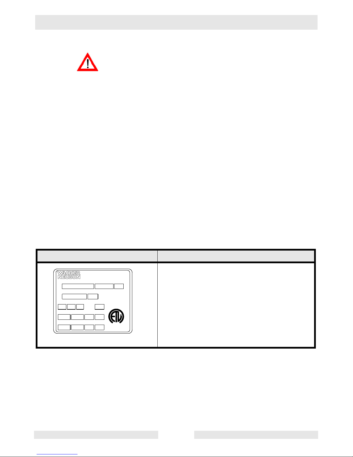
1.2 Informational Labels
Label Meaning
A nameplate listing the model number, item num-
Wacker Neuson Corporation
Phase
Menomonee Falls, WI 53051 USA
Man. Y/M
THERMALLY PROTECTED
INDOORS OR OUTDOORS
CSA ENCLOSURE 3
Amp.
Conforms to UL S td. 778
Cert. to CAN/CSA St d.
C22.2 No. 108-M89
kWkgMax. L/minMax. m
HPlbsMax. GPMMax. ft
CUS
MADE IN TAIWAN
Model Item No. Rev.
Serial No.
VHz
L
I
S
2001993
R
D
E
T
ber, revision number, and serial number is
attached to each unit. Please record the information found on this plate so it will be available
should the nameplate become lost or damaged.
When ordering parts or requesting service information, you will always be asked to specify the
model number, item number, revision number,
and serial number of the unit.
wc_si000034gb.fm 8
Page 9
PST2/PSTF2 400 Operation
2. Operation
2.1 Names of Parts
See Graphic: wc_gr001699
15
1
5
2
8
3
9
10
12
13
6
11
Ref Description Ref Description
1 Lifting handle 9 Oil plug
2 Mechanical seal 10 Dust seal
3 Lubricant 11 Sleev e
4 Oil housing 12 Impeller
5 Coupling 13 Stirrer nut
6 Volute 14 Strainer
7 Gasket 15 Oil lifter
8 Cable assembly
wc_tx000111gb.fm 9
14
wc_gr001699
Page 10
Operation PST2/PSTF2 400
2.2 Prior to Operation
When the pump is delivered, first perform the following checks:
• Inspection
While unpacking, inspect the product for damage during shipment, and
make sure all bolts and nuts are tightened properly.
• Specification check
Check the model number to make sure it is the product that was
ordered. Be certain it is the correct voltage and frequency.
Note: If there is any problem with the product as shipped, contact your
nearest dealer or Wacker Neuson representative at once.
• Product specifications
Do not operate this product under any conditions other than those for
which it is specified. Failure to observe this precaution can lead to
CAUTION
electrical shock, current leakage, fire, water leakage or other
problems.
2.3 Installation
If the pump is used to drain a swimming pool, the pump must be
connected to a Ground Fault Interrupter (GFI).
WARNING
If the pump is used in fountains, the pump must be connected to a
Ground Fault Interrupter (GFI).
The pump must not be used when people are in the water.
Leakage of pump lubricants may cause pollution of water.
Proper plug must be provided according to local codes and standards.
Refer to wiring diagram.
Do not use this pump in liquids other than water, such as oil, salt water,
or organic solvents.
Use with a power supply voltage within ±5% of the rated voltage.
Do not use in water temperatures outside the range of 0–40°C
(32–104°F) which can lead to failure, current leakage or shock.
Do not use in the vicinity of explosive or flammable materials.
Use only in fully assembled state.
Note: Consult your local dealer or Wacker Neuson representative
before using with any liquids other than those indicated in this
document.
wc_tx000111gb.fm 10
Page 11
PST2/PSTF2 400 Operation
Preparing for installation
Before installing the pump at a work site, you will need to have the
following tools and instruments ready:
• Insulation resistance tester (megohmmeter)
• AC voltmeter
• AC ammeter (clamp-on type)
• Bolt and nut tighteners
• Power supply connection tools (screwdriver or box wrench)
Note: Please also read the instructions that come with each of the test
instruments.
Checks to Make Before Installation
When a three-prong grounded plug is used:
Use the megohmmeter to measure the motor insulation resistance
between the grounding prong and each one of the two power prongs.
When connection wires are used:
With the megohmmeter, measure the insulation resistance between
the ground wire (Green) and each one of the two power wires.
Reference insulation resistance: 20MW or greater.
Note: The reference insulation resistance (20MW or greater) is the
value when the pump is new or has been repaired. For the reference
value after installation, see the Periodic Maintenance table.
Precautions in Installation
When installing the pump, pay close attention to its center of gravity
and weight. If it is not lowered into place correctly, it may fall and be
WARNING
damaged or cause injury.
When transporting the machine by hand, be sure to employ manpower
commensurate with the weight of the machine. To avoid back injury
when lifting the machine, bend the knees to pick it up rather than
bending your back only.
Do not under any circumstances install or move the pump by
suspending it from the cable assembly. The cable may be damaged,
CAUTION
causing current leakage, shock, or fire.
2.3.1 Avoid dropping the pump or other strong impact. Lift the pump by
holding it firmly with the hands or by attaching a rope or chain to the
lifting handle.
Note: On cable assembly handling, see Electrical Wiring.
Avoid dry operation, which will not only lower performance but can
cause the pump to malfunction, leading to electrical leakage and
CAUTION
wc_tx000111gb.fm 11
shock.
Page 12
Operation PST2/PSTF2 400
2.3.2 Install the pump in a location with sufficient water level, where water
collects readily.
Note: See Operation (“Operating Water Level”) for the water level
necessary for operation.
Note: The discharge end of the hose should be located higher than the
water surface. If the end of the hose is submerged, water may flow
back to the pump when the pump is stopped; and if the hose end is
lower than the water surface, water may overflow when the pump is
turned off.
If large quantities of earth are sucked up, damage resulting from
friction in the pump can lead to current leakage and shock.
CAUTION
2.3.3 Use the pump in the upright position. To prevent the strainer from
becoming submerged in mud, causing it to suck in sand or debris,
mount it on a block or other firm base.
2.3.4 If used in a permanent installation where the pump is not readily
accessible after installation, please contact Wacker Neuson for a
duplicate nameplate to be installed at the wellhead or on the control
box so that it will be readily visible.
wc_tx000111gb.fm 12
Page 13
PST2/PSTF2 400 Operation
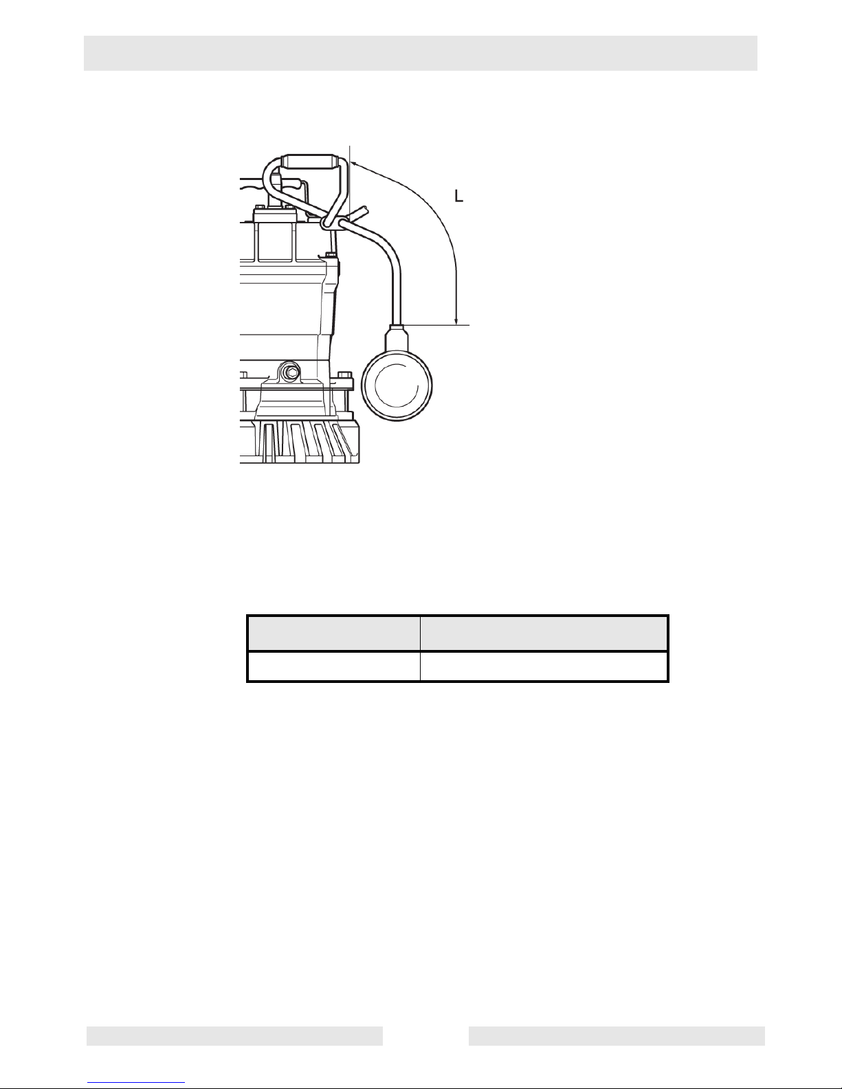
2.4 Installing the Float (if equipped)
See graphic: wc_gr005664
wc_gr005664
2.4.1 Set the length of the float lead wire to the dimension indicated below.
Failure to set the correct lead wire length will lead to improper
operation of the pump.
Pump model Length “L”
PSTF2 400 150 mm (5.9 in.)
NOTICE: Install the float so that it moves freely up and down. If the
float binds or catches, it will cause the pump to operate improperly.
wc_tx000111gb.fm 13
Page 14

Operation PST2/PSTF2 400
Notes:
wc_tx000111gb.fm 14
Page 15
PST2/PSTF2 400 Operation
2.5 Electrical Wiring
Performing electrical wiring
Electrical wiring should be performed by a qualified person in accord
with all applicable regulations. Failure to observe this precaution not
WARNING
WARNING
only risks breaking the law but is extremely dangerous.
Incorrect wiring can lead to current leakage, electrical shock or fire.
Always make sure the pump is equipped with the specified overload
protectors and fuses or breakers, so as to prevent electrical shock from
a current leak or pump malfunction.
Operate within the capacity of the power supply and wiring.
Grounding
Do not use the pump without first grounding it properly. Failure to
ground it can lead to electrical shock from a current leak or pump
malfunction.
CAUTION
WARNING
CAUTION
Do not attach the grounding wire to a gas pipe, water pipe, lightning
arrester or telephone grounding wire. Improper grounding can result in
electrical shock.
Connecting the power supply
Before connecting wires to the terminal, make certain the power supply
is turned off (circuit breaker, etc.), to avoid electrical shock, shorting,
or unexpected starting of the pump, leading to injury.
Before inserting the power supply plug, make certain the power supply
is turned off (circuit breaker, etc.), to avoid electrical shock, shorting,
or unexpected starting of the pump, leading to injury.
Do not use the pump with the cable assembly or plug connected
loosely, which can result in electric shock, shorting, or fire.
Draw power from a dedicated power outlet rated at 15 A or above.
Sharing the outlet with other equipment may cause overheating at the
branch outlet and could result in fire.
• The three-prong grounded plug shall be connected as shown in
the drawing.
NOTICE: Be sure to use a dedicated power supply with a ground
leakage circuit breaker.
Note: The shape of the plug may differ from that shown in the
illustration.
wc_tx000111gb.fm 15
Page 16

Operation PST2/PSTF2 400
See Graphic: wc_gr000242
Cable Assembly
If it is necessary to extend the cable assembly, use a core size equal
to or larger than the original. This is necessary not only to avoid a
CAUTION
performance drop, but to prevent cable overheating which can result in
fire, electrical leakage or electrical shock.
If a cable with cut insulation or other damage is submerged in the
water, there is a danger of damage to the pump, electrical leakage,
electrical shock, or fire.
Be careful not to let the cable assembly be cut or become twisted. This
may result in damage to the pump, electrical leakage, electrical shock,
or fire.
If it is necessary to submerge the connection wires of the cable
assembly in water, first seal the wires completely in a molded
protective sleeve, to prevent electrical leakage, electrical shock, or fire.
Do not allow the cable assembly wires or power supply plug to become
wet.
Make sure the cable does not become excessively bent or twisted, and
does not rub against a structure in a way that might damage it.
If used in a deep-well installation, the cable assembly should be
secured every twenty feet.
wc_tx000111gb.fm 16
Page 17

PST2/PSTF2 400 Operation
R
R
1
W
W
B
L
3
2
5
4
6
G
G/Y
2.6 Electrical Circuit Diagrams
See Graphic: wc_gr006190
PST2 400
G/Y
8
R(Br)
W (L)
6
Ref. Description Ref. Description
CAUTION
If connected to a circuit protected by a fuse, use a time-delay fuse with
this pump.
R
5
Y/G
PSTF2 400
LL
B
W
4
wc_gr006190
1
2
3
1 Capacitor 5 Frame grounding
2 Main coil 6 Ground
3 Auxiliary coil 8 Float switch (normally open
4 Miniature protector
wc_tx000111gb.fm 17
contact)
Page 18

Operation PST2/PSTF2 400
Wire Colors
B Black V Violet Or Orange
G Green W White Pr Purple
L Blue Y Yellow Sh Shield
P Pink Br Brown LL Light Blue
R Red Cl Clear G/Y Green/Yellow
TTan GrGray
wc_tx000111gb.fm 18
Page 19

PST2/PSTF2 400 Operation
2.7 Operation
Before starting
2.7.1 Make sure once again that the product is of the correct voltage and
frequency rating.
NOTICE: Using the product at other than rated voltage and frequency
will not only lower its performance but may damage the product.
Note: Confirm the rated voltage and frequency on the model
nameplate.
2.7.2 Confirm the wiring, supply voltage, circuit breaker capacity, and motor
insulation resistance.
Reference insulation resistance = 20 MW or greater.
Note: The reference insulation resistance (20 MW or greater) is the
value when the pump is new or has been repaired. For the reference
value after installation see “Periodic Maintenance Table.”
2.7.3 The setting on the circuit breaker or other overload protector should be
made in accord with the rated current of the pump.
Note: See “Operating Specifications” fo r the rated current of the pump.
2.7.4 When powering the pump with a generator, be certain the generator is
sized to supply the required power for the pump and any other
equipment powered by the generator.
Test Operation
Do not operate the pump while it is suspended in the air. The recoil
may result in injury or other major accident.
WARNING
Do not start the pump when people are standing next to it. A current
leak can result in electrical shock.
WARNING
Run the pump for a short time (3–10 minutes) and confirm the
following:
• Using an ammeter (clamp-on type), measure the operating
current at the L1 and L2 phase wires on the terminal.
COUNTERMEASURE: If the operating current exceeds the rated
value, pump motor overload may be a cause. Make sure the pump has
been installed under proper conditions as described in Installation.
• Using an AC voltmeter (tester), measure voltage at the terminals.
Supply voltage tolerance: within ±5% of rated voltage.
wc_tx000111gb.fm 19
Page 20

Operation PST2/PSTF2 400
COUNTERMEASURE: If the supply voltage is outside the tolerance,
possible causes are the power supply capacity or an inadequate
extension cable. Look again at the wiring diagram and make sure the
conditions are proper.
In case of very excessive vibration, unusual noise or odor, turn off the
power immediately and consult your nearest dealer or Wacker
CAUTION
representative. Continuing to operate the pump under abnormal
conditions may result in electrical shock, fire, or current leakage.
Operation
The pump may become very hot during operation. Be careful not to
contact the pump accidentally to avoid being burned.
WARNING
CAUTION
Make sure no extraneous objects such as pins, nails or other metal
objects are sucked into the pump. These can damage the pump or
cause it to malfunction, and can result in electrical shock or electrical
leakage.
When the pump is not used for an extended period, be sure to turn off
the power (circuit breaker, etc.). Deterioration of the insulation may
lead to electrical leakage, electrical shock, or fire.
In case of a power outage, turn off the power to the pump to avoid
having it start unexpectedly when the power is restored, presenting
serious danger to people in the vicinity.
The pump may become hot during operation. Do not touch an
operating pump. Allow the pump to cool before handling.
Pay careful attention to the water level while the pump is operating. Dry
operation may cause the pump to malfunction.
Note: See section “Operating water level” for the water level
necessary for operation.
Sharp bends in the hose, especially near its base, may cause air
pockets to form resulting in idle operation. Lessen the degree of
bending while continuing to operate the pump.
wc_tx000111gb.fm 20
Page 21

PST2/PSTF2 400 Operation
Operating water level
Do not operate the pump below the C.W.L. (Continuous running Water
Level) indicated below. Failure to observe this condition may result in
CAUTION
damage to the pump, current leakage or electrical shock.
See Graphic: wc_gr001222
C.W.L
NPT 45-degree hose coupling is standard for the US market.
Pump Model Continuous running Water Level
PST2 400 w/strainer 90mm (3.5")
PST2 400 w/residue plate 10mm (0.4”)
PSTF2 400 120mm (4.75”)
Motor Protection System (Motor Protector)
The pump has a built-in motor protection system (Miniature Protector).
If the motor overheats, for reasons such as the following, the pump will
automatically stop operating regardless of the water level, to protect
the motor:
• Change in supply voltage polarity
• Overload
wc_gr001222
• Open-phase operation or operation under constraint
Note: Always determine the cause of the problem and resolve it before
resuming operation. Simply repeating cycles of stopping and restarting
will result in damage to the pump. Do not continue operation at very
low lift, low water level, or while the strainer is clogged with debris. Not
only will performance suffer, but also such conditions may cause
noise, heavy vibration, and malfunctioning.
wc_tx000111gb.fm 21
Page 22

Operation PST2/PSTF2 400
2.8 Automatic Operation (PSTF2 400 only)
See Graphic: wc_gr005666
The PSTF2 400 pump is equipped with a float switch to detect the
water level. The float switch (a) enables the pump to perform an
automatic drainage operation when connected to a continuous power
supply.
a
wc_gr005666
Connect the power and perform a trial operation as follows:
2.8.1 Move the float switch down to its lowest position.
2.8.2 Raise the float switch. This will start the pump.
2.8.3 Lower the float switch to its original position. This will stop the pump.
2.8.4 Repeat this cycle two or three more times to verify the operation.
Note: The trial operation must be completed within one minute.
If the pump operates abnormally (i.e. exhibits an unusually large
amount of vibration, noise, or odor), disconnect the power supply
CAUTION
immediately and contact your Wacker Neuson dealer. Do not operate
the pump in this condition, otherwise there is a risk of current leakage,
electrical shock, or fire.
wc_tx000111gb.fm 22
Page 23

PST2/PSTF2 400 Operation
2.9 Residue Plate
See graphic: wc_gr001144
The residue plate kit contains the residue plate, washers, and bolts.
Reuse nuts from pump assembly.
2.9.1 Remove the strainer (3) by loosening the three nuts (1) and removing
the three bolts (2). Keep nuts for reuse.
2.9.2 Position washers (4) and attach the residue plate (5) with new bolts (6)
included with kit.
Note: Be certain to use washers to prevent motor shaft stirrer nut from
protruding through residue plate.
1
2
3
4
5
6
wc_gr001144
wc_tx000111gb.fm 23
Page 24

Maintenance PST2/PSTF2 400
3. Maintenance
3.1 Periodic Maintenance Table
Pump
Measure insulation resistance.
Reference insulation resistance =
1MW or greater. (1)
Measure operating current.
Compare with rated current.
Measure supply voltage.
Compare with allowable range (within ±5% of rated
voltage).
Pump inspection.
A noticeable drop in performance may indicate
wear in the impeller, etc., or else clogging of the
strainer, etc. Remove the clogged debris and
replace any worn parts.
Lubricant inspection.
Change lubricant.
Weekly Monthly Every
1000
hrs.
■
■
■
■
■
Every
2000
hrs.
■
Designated lubricant: SAE 10W/20W. (2)
Change mechanical seal. (3)
Overhaul.
This should be carried out even if there are no problems with the pump. The frequency depends on
how continuously the pump is in use. (4)
(1) If the insulation resistance has become noticeably lower than the previous inspection, an inspec-
tion of the motor will be necessary.
(2) See Lubricant Inspection and Lubricant Change in this section.
(3) Specialized know-how is required for inspecting and replacing the mechanical seal. Consult with
your nearest dealer or Wacker Neuson representative.
(4) Consult with your nearest dealer or Wacker Neuson representative regarding overhauls.
■
■
■
wc_tx000112_orig_gb.fm 24
Page 25

PST2/PSTF2 400 Maintenance
3.2 Maintenance and Inspection
Regular maintenance and inspections are a necessity for continued
efficient functioning of the pump. If any abnormal conditions are
noticed, refer to the Troubleshooting section and take corrective
measures immediately. It is recommended that a spare pump be kept
ready in case of any problems.
Prior to inspecting
Before inspecting the pump, make certain the power supply (circuit
breaker, etc.) is turned off. Then, unplug the cable assembly from the
WARNING
3.2.1 Washing the pump
3.2.2 Inspecting the pump exterior
receptacle or detach it from the terminals. Failure to follow this
precaution may result in a serious accident from electrical shock or
unexpected starting of the pump motor.
Remove accumulated matter from the surface of the pump and wash
it with clean water. Take special care to remove any debris from the
impeller.
Look for any peeling or chipped paint, and make sure the nuts and
bolts are fastened tightly. Any cracks in the surface should be repaired
by cleaning that area, drying it and then applying a touch-up coating.
Note: Touch-up paint is not supplied. Note that some kinds of damage
or looseness may require that the unit be disassembled for repairs.
Please consult your nearest dealer or Wacker Neuson representative.
Storage
When the pump is out of use for an extended period, wash it and dry it
thoroughly, then store it indoors.
Note: Always run a test operation before putting the pump back into
service.
If the pump is left in the water, it should be run a minimum of once a
week.
• Inspecting Lubricant
Remove the oil plug and tilt the pump to drain a small amount of
lubricant. If the lubricant is milky white or has water mixed in with it, the
mechanical seal may be faulty. In this case the pump will need to be
disassembled and repaired.
• Replacing Lubricant
Remove the oil plug and drain all the lubricant, then replace it with the
specified amount.
Note: Worn lubricant and other waste products should be disposed of
by a qualified agent, in accord with applicable laws. The oil plug gasket
should be replaced each time the lubricant is inspected or changed.
wc_tx000112_orig_gb.fm 25
Page 26

Maintenance PST2/PSTF2 400
See Graphic: wc_gr000245
Ref. Description Ref. Description
1 Oil inlet 3 Oil plug
2 Gasket 4 Allen wrench
Pump Model Lubricant Capacity
PST2 400
160 ml (5.4 fl. oz.)
PSTF2 400
Replacement Parts
The table lists the parts that need to be replaced periodically. Replace
these using the recommended frequency as a guideline.
Part Replacement Frequency
Mechanical seal When lubricant in oil compar tment becomes milky.
Lubricant (SAE 10W/20W) Every 2,000 hours or 12 months, whichever comes first.
Gasket Each time pump is disassembled or inspected.
Dust seal When ring is worn, and each time pump is disassem-
bled or inspected.
Sleeve When it becomes worn.
wc_tx000112_orig_gb.fm 26
Page 27

PST2/PSTF2 400 Maintenance
3.3 Disassembly and Reassembly
Before disassembling the pump, make certain the power supply (circuit
breaker, etc.) is turned off. Then, unplug the cable assembly from the
WARNING
receptacle or detach it from the terminals. To avoid electrical shock,
DO NOT work with wet hands.
NEVER check the operation of any parts (impeller rotation, etc.) by
turning on the power while the unit is partially assembled. Failure to
observe these precautions may result in a serious accident.
DO NOT disassemble or repair any parts other than those designated
here. If repairs are necessary in any other than the designated parts,
consult your nearest dealer or Wacker Neuson representative.
Improper repairs can result in electrical leakage, electrical shock, fire,
or water leaks.
After reassembly, ALWAYS perform a test operation before resuming
use of the pump. Improper assembly will cause the pump to
malfunction, resulting in electric shock or water leaks.
The procedure for disassembly and reassembly is shown here to the
extent necessary for impeller replacement. A specialized environment
and facilities are necessary for work on the mechanical seal and the
motor parts. Contact your nearest dealer or Wacker Neuson
representative in the event such repairs are necessary.
wc_tx000112_orig_gb.fm 27
Page 28

Maintenance PST2/PSTF2 400
3.4 Disassembly
See Graphic: wc_gr000411
Note: For assembly or disassembly, place the pump on its side.
Note: It is not necessary to drain the oil for disassembly and inspect
ion of the impeller (w) or volute (aa). However, drain oil if further
disassembly and testing is required.
3.4.1 Remove three nuts (af) and the suction strainer (ac).
3.4.2 Remove volute (aa) and volute gasket (ah).
3.4.3 While keeping the impeller (w) from rotating, remove stirrer nut (z),
lockwasher (y) and washer (x).
Impeller vanes may be very sharp due to excessive wear. Handle with
care.
CAUTION
3.4.4 Remove impeller (w).
Note: If the parts are worn or damaged, make sure to replace them
with new ones.
wc_tx000112_orig_gb.fm 28
Page 29

PST2/PSTF2 400 Maintenance
3.5 Impeller Inspection
See Graphic: wc_gr000411
3.5.1 Visually inspect impeller (w) for corrosion, wear or damage. Worn
impellers compromise peak performance.
3.5.2 Visually inspect impeller key and rotor shaft keyway for signs of
uneven wear.
3.5.3 Visually inspect volute (aa) casting for cracks, wear and damage. Look
for signs of wear on volute cutwaters and surfaces facing impeller.
wc_tx000112_orig_gb.fm 29
Page 30

Maintenance PST2/PSTF2 400
3.6 Impeller Reassembly
See Graphic: wc_gr000411
Note: If, upon inspection and testing, a pump component requires
replacement, use only original manufacturer’s replacement parts.
3.6.1 Turn pump on its side.
3.6.2 Pre-assemble the dust seal (u) and sleeve (v). Slide the two pieces
(u & v) onto the rotor shaft. DO NOT apply oil to the surface where the
dust seal (u) contacts the sleeve (v).
3.6.3 Align keyway of impeller (w) with keyway of rotor (not shown) and push
impeller (w) onto rotor shaft.
3.6.4 Secure with washer (x), lockwasher (y) and stirrer nut (z).
3.6.5 While holding the impeller from rotating, tighten stirrer nut (z).
3.6.6 Position volute (aa) on suction strainer (ac), aligning with the three
bolts (ab) protruding from the suction strainer (ac).
3.6.7 Replace gasket (ah) on top of volute (aa).
3.6.8 Lift and hold remaining pump assembly in an upright position, align
three mounting flanges and lower into place.
3.6.9 Assemble and secure three nuts (af).
3.6.10 Tighten three nuts (af).
3.6.11 Pre-test pump to verify proper operation.
3.6.12 Performance test pump. Test results should be:
Maximum head > 10.06m (33ft)
Maximum volume > 170.3 ltr/min (45gpm)
wc_tx000112_orig_gb.fm 30
Page 31

PST2/PSTF2 400 Maintenance
3.7 Troubleshooting
Before ordering repairs, carefully read through this manual, then
repeat the inspection. If the problem remains, contact your nearest
dealer or Wacker Neuson representative.
Always turn off the power before inspecting the pump. Failure to
observe this precaution can result in serious accident.
WARNING
Problem / Symptom Reason / Remedy
Pump will not start • Power is off. Restore power.
• Cable assembly is cut or not connected prope rly. Repair/
replace the cable or fix the connection.
• Impeller is clogged. Inspect the pump and remove any debris.
Pump stops soon after
starting
(Motor protector operates)
Pump does not stop automatically • Float (if equipped) is obstructed, not moving freely, or malfunc-
Poor lift or discharge
capacity
• Impeller is clogged. Remove debris.
• Low voltage. Provide the rated voltage, or make sure the cable
assembly extension is the proper standard.
• Wrong power frequency. Check the nameplate, and repla ce
the pump or the impeller.
• Extended operation with a clogged strainer. Remove debris
from the strainer.
tioning. Remove obstructions. Repa ir or replace float switch if
necessary.
• Water level of float (if equipped) set lower than pump’s minimum operating water level. Set float higher than pump’s minimum operating water level.
• Malfunction in level relay unit. Repair or replace level relay unit.
• Electrode shorted by debris. Use sandpaper to remove debris
from electrode.
• Electrical interference in vicinity of pump. Check for tangled
wires around electrode. Check f or nearb y electrical devices that
could generate electromagnetic interference; relocate pump if
necessary.
• Faulty motor. Repair or replace the motor.
• Excessive sand is discharged. Place the pump on a block or
other base to prevent the sand from being sucked into it.
• Worn out impeller. Replace.
• Sharply bent or clogged hose. Straighten out any sharp bends.
Enclose the pump with a screen to keep away debris.
• Strainer clogged or buried. Remov e debris from the str ainer , or
place a block under the pu mp.
Heavy vibration or noise • Damaged motor shaft. Contact dealer and replace motor.
wc_tx000112_orig_gb.fm 31
Page 32

Technical Data PST2/PSTF2 400
4. Technical Data
4.1 Standard Specifications
Applicable Liquids,
Rain Water, Ground Water, Sand-Carrying Water
Consistency and
Temperature
0–40°C (32–104°F)
Pump Impeller Semi-Vortex Type
Shaft Seal Double Mechanical Seal
Bearing Shielded Ball Bearing
Motor Specification Dry Submersible Induction Motor
(2-Pole)
Insulation Class E
Protection System Miniature Protector
Lubricant SAE 10W/20W
Such as:
–Turbine Oil ISO VG #32
–Shell Victrolia Oil #27
–British Pet Energol THB #32
–Gulf Paramount #32
–Tellus #T22 Shell Oil
–Shell Turbo T32
Connection Coupling (NPT 2”)
wc_td000034gb.fm 32
Page 33

PST2/PSTF2 400 Technical Data
4.2 Operating Specifications
Part No. PST2 400 / PSTF2 400
Pump
Electric Power
Rated Current
V/Ph/Hz
110/1/60
A
5.4
Starting Method Capacitor-Run
Bore
Output
Maximum Head
Maximum Capacity
Maximum Pressure
Solid Size Capacity
Weight*
mm (in.)
kW (Hp)
m (ft.)
L/min
(GPM)
psi
mm (in.)
Kg (lbs.)
50 (2)
0.40 (0.50)
12 (39)
200 (53)
16.8
9.5 (0.4)
11.3 (25)
*The weight (mass) given above is the operating weight of the pump itself, not including the cable
assembly.
wc_td000034gb.fm 33
Page 34

Technical Data PST2/PSTF2 400
4.3 Dimensions
4.3.1
340***
(13.5)
250
(9.8)
PST2 400
185
(7.3)
(13.0)
330
328
(12.9)
(6.4)
162
(3.3)
84
255
(10.1)
2"
45°
207
(8.1)
PSTF2 400
185
(7.3)
40**
(1.6)
90*
(3.5)
385****
(15.2)
120***
(4.8)
*Start range
** Stop range
*** Minimum
**** Maximum
wc_td000034gb.fm 34
wc_gr006191
Page 35

Page 36

Page 37

Page 38

Page 39

Page 40

Page 41

Page 42

Page 43

Page 44

Page 45

Page 46

Page 47

Page 48

Important: For spare parts information, please see your Wacker Neuson Dealer, or visit the
Wacker Neuson website at http:/ /www.wackerneuson.com/.
Wichtig! Informationen über Ersatzteile erhalten Sie von Ihrem Wacker Neuson Händler oder
besuchen Sie die Wacker Neuson Website unter http://www.wackerneuson.com/.
Important : Pour des informations sur les pièces détachées, merci de consulter votre
distributeur Wacker Neuson, ou de visiter le site I nternet de Wacker Neuson sur
http://www.wackerneuson.com/.
Importante : Para saber más sobre las piezas de repuesto, póngase en contacto con su
distribuidor de Wacker Neuson o acceda al sitio web de Wacker Neuson en
http://www.wackerneuson.com/.
Importante : Per informazioni sui pezzi di ricambio, contattare il rivenditore Wacker Neuson o
visitare il sito di Wacker Neuson all’indirizzo www.wackerneuson.com.
Viktigt : För information om reservdelar, kontakta din Wacker Neuson-leverantör eller besök
Wacker Neusons webbplats på http://www.wackerneuson.com/.
Tärkeää : Pyydä varaosatietoja Wacker Neusonin jälleenmyyjältä tai vi erai le Wacker Neusonin
web-sivustolla osoitteessa http://www.wackerneuson.com/
Viktig : For i nformasjon om reservedeler, vennligst kontakt din Wacker Neuson-f orhandler, eller
besøk Wacker Neusons nettside på http://www.wackerneuson.com/.
Vigtigt : Hvis du ønsker oplysninger om reservedele, bedes du kontakte din Wacker Neuson
forhandler eller besøg Wacker Neuson websiden på http://www.wackerneuson.com/.
Belangrijk! Neem contact op met uw W acker Neuson dealer of bezoek de website van W a cker
Neuson op http://www.wackerneuson.com/ voor meer informatie over reserveonderdelen.
Importante : Para obter informações sobre as peças sobresselentes, consulte o seu
fornecedor da Wacker Neuson ou aceda ao site Web da Wacker Neuson em
http://www.wackerneuson.com
Ważne : W celu uzyskania informacji na temat części zamiennych skontaktuj się z
przedstawicielem firmy Wacker Neuson lub skorzystaj z witryny internetowej
http://wackerneuson.com/.
Důležité upozornění! Pro informace o náhradních dílech, prosím, kontaktujte svého Wacker
Neuson dealera, nebo navštivte webové stránky http://www.wackerneuson.com/.
FONTOS: A pótalkatrészekre vonatkozó információkért kérjük, forduljon Wacker Neuson
kereskedőjéhez vagy látogasson el a Wacker Neuson webol dalára a következő címen:
http://www.wackerneuson.com/.
Важно! Для ознакомления с информацией о запасных частях, пожалуйста, обратитесь к
местному торговому представителю компании Wacker Neuson или посетите веб-сайт
http://www.wackerneuson.com/.
Σημαντικό : Γι
α πληροφορίες σχ
ετικά με τα ανταλλακτικά, μιλήστε με τον αντιπρόσωπό σας της
Wacker Neuson, ή επισκεφθείτε τον ιστότοπο http://www.wackerneuson.com/.
Važno : Za rezervne dijelove obratite se svom Wacker Neuson prodavaču ili posjetite mrežne
stranice tvrtke Wacker Neuson: http://www.wackerneuson.com/.
Önemli : Yedek parça bilgileri için Wacker Neuson Bayinize bakın veya Wacker Neuson web
sitesini ziyaret edin. http://www.wackerneuson.com/
重要 交換部品の情報については、ワッカーノイソンディーラーにお問い合わせ頂くか、ワッ
カーノイソンウェブサイト http://www.wackerneuson.com/ をご覧ください。
重要 有关备件信息,请咨询您的威克诺森经销商或访问威克诺森网站:
http://www.wackerneuson.com/。
Important : Pentru informaţii referitoare la piesele de schimb, vă rugăm să vă adresaţi
distribuitorului Wacker Neuson sau să vizitaţi site-ul web Wacker Neuson l a adresa
http://www.wackerneuson.com/.
Важно : За информация относно резервни части, моля, обърнете се към местния дилър
на W
acker Neuson или по
сетете уебсайта на Wacker Neuson на адрес
http://www.wackerneuson.com/.
Wacker Neuson Produktion GmbH & Co. KG, Preußenstraße 41, D-80809 München,
Wacker Neuson Production Americas LLC, N92W15000 Anthony Ave., Menomonee Falls, WI. 53051
Wacker Neuson Limited - Room 1701–03 & 1717–20, 17/F. Tower 1, Grand Century Place, 193 Prince Edward
Road West, Mongkok, Kowloon, Hongkong. Tel: (852) 3605 5360, Fax: (852) 2758 0032
Tel.: +49-(0)89-3 54 02-0 Fax: +49 - (0)89-3 54 02-390
Tel.: (262) 255-0500 Fax: (262) 255-0550 Tel.: (800) 770-0957
 Loading...