

Page 1

Operator’s Manual
5000187971
Pump
PSR1 500
Type PSR1 500
Document 5000187971
Date 1115
Revision 03
Language EN
Page 2

Copyright notice
© Copyright 2015 by Wacker Neuson Production Americas LLC
All rights, including copying and distribution rights, are reserved.
This publication may be photocopied by the original purchaser of the
machine. Any other type of reproduction is prohibited without express
written permission from Wacker Neuson Production Americas LLC.
Any type of reproduction or distribution not authorized by Wacker
Neuson Production Americas LLC represents an infringement of valid
copyrights. Violators will be prosecuted.
Trademarks
Manufacturer
Original instructions
All trademarks referenced in this manual are the property of their
respective owners.
Wacker Neuson Production Americas LLC
N92W15000 Anthony Avenue
Menomonee Falls, WI 53051 U.S.A.
Tel: (262) 255-0500 · Fax: (262) 255-0550 · Tel: (800) 770-0957
www.wackerneuson.com
This Operator’s Manual presents the original instructions. The original
language of this Operator’s Manual is American English.
Page 3

PSR1 500 Foreword
Foreword
SAVE THESE INSTRUCTIONS—This manual contains important instructions for
the machine models below. These instructions have been written expressly by
Wacker Neuson Production Americas LLC and must be followed during installation,
operation, and maintenance of the machines.
Machines
covered in
this manual
Machine Item Number
PSR1 500 0620411
Machine
documentation
Expectations
for
information in
this manual
From this point forward in this documentation, Wacker Neuson Production
Americas LLC will be referred to as Wacker Neuson.
Keep a copy of the Operator’s Manual with the machine at all times.
Use the separate Parts Book supplied with the machine to order replacement
parts.
Refer to the separate Repair Manual for detailed instructions on servicing and
repairing the machine.
If you are missing any of these documents, please contact Wacker Neuson to
order a replacement or visit www.wackerneuson.com.
When ordering parts or requesting service information, be prepared to provide
the machine model number, item number, revision number, and serial number.
This manual provides information and procedures to safely operate and
maintain the above Wacker Neuson model(s). For your own safety and to
reduce the risk of injury, carefully read, understand, and observe all instructions
described in this manual.
Wacker Neuson expressly reserves the right to make technical modifications,
even without notice, which improve the performance or safety standards of its
machines.
The information contained in this manual is based on machines manufactured
up until the time of publication. Wacker Neuson reserves the right to change
any portion of this information without notice.
Manufacturer’s
approval
This manual contains references to approved parts, attachments, and
modifications. The following definitions apply:
Approved parts or attachments are those either manufactured or provided by
Wacker Neuson.
Approved modifications are those performed by an authorized Wacker
Neuson service center according to written instructions published by Wacker
Neuson.
Unapproved parts, attachments, and modifications are those that do not
meet the approved criteria.
Unapproved parts, attachments, or modifications may have the following
consequences:
Serious injury hazards to the operator and persons in the work area
wc_tx002042gb.fm 3
Page 4

Foreword PSR1 500
Permanent damage to the machine which will not be covered under warranty
Contact your Wacker Neuson dealer immediately if you have questions about
approved or unapproved parts, attachments, or modifications.
4 wc_tx002042gb.fm
Page 5

Table of ContentsPSR1 500
Foreword 3
1 Safety Information 7
1.1 Signal Words Used in this Manual ....................................................... 7
1.2 Machine Description and Intended Use ............................................... 8
1.3 Operating and Electrical Safety ............................................................ 9
1.4 Service Safety .................................................................................... 10
1.5 Labels ................................................................................................. 11
2 Lifting and Transporting 12
3 Installation 13
3.1 Components ....................................................................................... 13
3.2 Preparing the Machine for First Use ................................................... 14
3.3 Application Area ................................................................................. 14
3.4 Preparing for Installation .................................................................... 15
3.5 Checks to Make Before Installation .................................................... 16
3.6 Electrical Wiring .................................................................................. 16
3.7 Connecting the Power Supply ............................................................ 17
3.8 Cable Assembly ................................................................................. 18
4 Operation 19
4.1 Before Starting ................................................................................... 19
4.2 Operating Water Level ..................................................................... 21
4.3 Emergency Shutdown Procedure ....................................................... 21
5 Maintenance 22
5.1 Periodic Maintenance Schedule ......................................................... 22
5.2 Maintenance and Inspection .............................................................. 23
5.3 Storage ............................................................................................... 23
5.4 Disassembly and Reassembly ........................................................... 25
5.5 Disassembly ....................................................................................... 26
5.6 Reassembly ........................................................................................ 27
5.7 Troubleshooting .................................................................................. 28
wc_bo5000187971_03TOC.fm 5
Page 6

Table of Contents PSR1 500
6 Technical Data 29
6.1 Standard Specifications .......................................................................29
6.2 Operating Specifications .....................................................................30
6.3 Dimensions .........................................................................................30
7 Schematics 31
8 AEM Safety Manual 33
6 wc_bo5000187971_03TOC.fm
Page 7
PSR1 500 Safety Information
1 Safety Information
1.1 Signal Words Used in this Manual
This manual contains DANGER, WARNING, CAUTION, NOTICE, and
NOTE signal words which must be followed to reduce the possibility
of personal injury, damage to the equipment, or improper service.
This is the safety alert symbol. It is used to alert you to potential personal hazards.
f Obey all safety messages that follow this symbol.
DANGER
DANGER indicates a hazardous situation which, if not avoided, will result in death
or serious injury.
To avoid death or serious injury from this type of hazard, obey all safety messages that
f
follow this signal word.
WARNING
WARNING indicates a hazardous situation which, if not avoided, could result in
death or serious injury.
To avoid possible death or serious injury from this type of hazard, obey all safety
f
messages that follow this signal word.
CAUTION
CAUTION indicates a hazardous situation which, if not avoided, could result in
minor or moderate injury.
To avoid possible minor or moderate injury from this type of hazard, obey all safety
f
messages that follow this signal word.
NOTICE: Used without the safety alert symbol, NOTICE indicates a
situation which, if not avoided, could result in property damage.
Note: A Note contains additional information important to a procedure.
wc_si000248gb.fm 7
Page 8

Safety Information PSR1 500
1.2 Machine Description and Intended Use
This machine is a submersible water pump. The Wacker Neuson
Submersible Pump consists of an electric motor, an impeller, a strainer,
and a metal casing with ports for water suction and discharge. Power is
supplied to the pump through a corded plug or a hard-wired connection,
depending on the installation. The operator connects hoses to the pump
and routes them so that water is pumped from the work area and
discharged into an appropriate location.
This machine is intended to be used for general de-watering applications.
This machine is intended for the pumping of clear water, or water
containing solids up to the size stated within the products specifications,
and up to the flow, head, and suction lift limits also stated within the
product specifications.
This machine has been designed and built strictly for the intended use
described above. Using the machine for any other purpose could
permanently damage the machine or seriously injure the operator or other
persons in the area. Machine damage caused by misuse is not covered
under warranty.
The following are some examples of misuse:
• Pumping flammable, explosive, or corrosive fluids
• Pumping hot or volatile fluids that result in pump cavitation
• Operating the pump outside of product specifications due to
incorrect diameter hoses, incorrect length hoses, other inlet or
outlet restrictions, or excessive suction lift or head
• Using the machine as a ladder, support, or work surface
• Using the machine to carry or transport passengers or equipment
• Operating the machine outside of factory specifications
• Operating the machine in a manner inconsistent with all warnings
found on the machine and in the Operator’s Manual.
This machine has been designed and built in accordance with the latest
global safety standards. It has been carefully engineered to eliminate
hazards as far as practicable and to increase operator safety through
protective guards and labeling. However, some risks may remain even
after protective measures have been taken. They are called residual
risks. On this machine, they may include exposure to:
• Electric shock from improper electrical connections or high
voltage
• Personal injury from improper lifting techniques
• Projectile hazard from discharge
8 wc_si000248gb.fm
Page 9

PSR1 500 Safety Information
To protect yourself and others, make sure you thoroughly read and
understand the safety information presented in this manual before
operating the machine.
Operator qualifications
Only trained personnel are permitted to start, operate, and shut down
the machine. They also must meet the following qualifications:
• have received instruction on how to properly use the machine
• are familiar with required safety devices
The machine must not be accessed or operated by:
•children
• people impaired by alcohol or drugs
Personal Protective Equipment (PPE)
Wear the following Personal Protective Equipment (PPE) while
operating this machine:
• Close-fitting work clothes that do not hinder movement
• Safety glasses with side shields
• Hearing protection
• Safety-toed footwear
Replacement parts
When replacement parts are required for this machine, use only
Wacker Neuson replacement parts or those parts equivalent to the
original in all types of specifications, such as physical dimensions,
type, strength, and material.
1.3 Operating and Electrical Safety
To reduce risk of electric shock, connect only to a properly grounded,
grounding-type receptacle.
WARNING
Risk of electric shock—this pump has not been investigated for use in
swimming pool areas.
An acceptable motor-control switch shall be provided at the time of
installation according to local codes and regulations.
To reduce risk of electric shock, follow instructions in this manual for
proper installation.
CAUTION: This pump may automatically restart. Prior to working on
the pump or control panel, all supply circuits must be disconnected.
CAUTION: Risk of shock—do not remove cord and strain relief.
wc_si000248gb.fm 9
Page 10

Safety Information PSR1 500
1.4 Service Safety
Service training
Before servicing or maintaining the machine:
• Read and understand the instructions contained in all manuals
delivered with the machine.
• Familiarize yourself with the location and proper use of all
controls and safety devices.
• Only trained personnel shall troubleshoot or repair problems
occurring with the machine.
• Contact Wacker Neuson for additional training if necessary.
When servicing or maintaining this machine:
• Do not allow improperly trained people to service or maintain the
machine. Personnel servicing or maintaining the machine must
be familiar with the associated potential risks and hazards.
Personal Protective Equipment (PPE)
Wear the following Personal Protective Equipment (PPE) while
servicing or maintaining this machine:
• Close-fitting work clothes that do not hinder movement
• Safety glasses with side shields
• Hearing protection
• Safety-toed footwear
In addition, before servicing or maintaining the machine:
• Tie back long hair.
• Remove all jewelry (including rings).
Replacing parts and labels
• Replace worn or damaged components.
• Replace all missing and hard-to-read labels.
• When replacing electrical components, use components that are
identical in rating and performance as the original components.
• When replacement parts are required for this machine, use only
Wacker Neuson replacement parts or those parts equivalent to
the original in all types of specifications, such as physical
dimensions, type, strength, and material.
10 wc_si000248gb.fm
Page 11

PSR1 500 Safety Information
1.5 Labels
Wacker Neuson Corporation
Model Item No. Rev.
Serial No.
VHz
Phase
Menomonee Falls, WI 53051 USA
Man. Y/
M
THERMALLY PROTECTED
INDOORS OR OUTDOORS
CSA ENCLOSURE
Amp.
Conforms to UL Std. 778
Cert. toCAN/CSA Std.
kWkgMax. L/minMax. m
HPlbsMax.GPMMax. ft
CUS
C22.2 No. 108-M89
L
I
S
2001993
A nameplate listing the model number, item number, revision number, and serial number is attached to each unit.
Please record the information found on this nameplate so it
will be available should the nameplate become lost or dam-
3
aged. When ordering parts or requesting service information, you will always be asked to specify the model number,
item number, revision number, and serial number of the
R
D
E
T
unit.
CAUTION
Do not attempt to operate this product before reading the
Operator’s Manual and understanding its contents.
Mishandling of this product may result in explosion, fire, or
electrical shock.
Do not pull on the power cord or use the power cord to lift
the pump.
Always use a dedicated ground leakage circuit breaker.
Be sure to install the ground wire securely.
Be sure to disconnect the power supply before handling
or inspecting the pump.
Never insert your hand into the pump inlet holes while the
pump is connected to the power supply.
wc_si000248gb.fm 11
Page 12
Lifting and Transporting PSR1 500
2 Lifting and Transporting
Do not under any circumstances install or move the pump by
suspending it from the cable assembly. The cable may be damaged,
WARNING
CAUTION
causing electrical leakage, shock, or fire.
When installing the pump, pay close attention to its center of gravity
and weight. If it is not lowered into place correctly, it may fall and be
damaged or cause injury.
When transporting the pump by hand, be sure to employ manpower
commensurate with the weight of the pump. To avoid back injury when
lifting the pump, bend the knees to pick it up rather than bending your
back only.
Avoid dropping the pump or other strong impact. Lift the pump by
holding it firmly with the hands or by attaching a rope or chain to the
handle.
12 wc_tx001963gb.fm
Page 13
PSR1 500 Installation
3 Installation
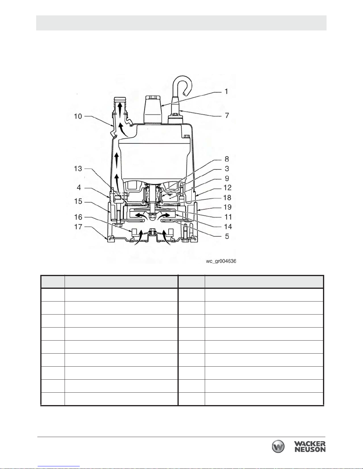
3.1 Components
Ref. Description Ref. Description
1 Lifting handle 11 Shaft sleeve
3 Oil lifter 12 Oil casing
4 Oil plug 13 Wear ring
5 Suction cover 14 Impeller
7 Cable assembly 15 Pump casing
8 Mechanical seal 16 Swing check valve
9 Lubricant 17 Bottom plate
10 Discharge outlet 18 V-ring
19 Stand
wc_tx001978gb.fm 13
Page 14
Installation PSR1 500
3.2 Preparing the Machine for First Use
When the pump is delivered, first perform the following checks:
• Inspection
While unpacking, inspect the product for damage during shipment, and
make sure all bolts and nuts are tightened properly.
• Specification check
Check the model number to make sure it is the product that was
ordered. Be certain it is the correct voltage and frequency.
Note: If there is any problem with the product as shipped, contact your
nearest dealer or Wacker Neuson representative at once.
• Product specifications
Do not operate this product under any conditions other than those for
which it is specified. Failure to observe this precaution can lead to
CAUTION
3.3 Application Area
electrical shock, current leakage, fire, water leakage or other
problems.
WARNING
If the pump is used for outdoor fountains, garden ponds and similar
places, or to drain a swimming pool, the pump must be supplied by an
isolating transformer or connected to a Residual Current Device (RCD)
with a residual operating current not exceeding 30 mA.
The pump must not be used when people are in the water.
Leakage of pump lubricants may cause pollution of water.
Proper plug must be provided according to local codes and standards.
Refer to wiring diagram.
Do not use this pump in liquids other than water, such as oil, salt water,
or organic solvents.
Use with a power supply voltage within ±5% of the rated voltage.
Do not use in water temperatures outside the range of 0–40°C
(32–104°F) which can lead to failure, electrical leakage or shock.
Do not use in the vicinity of explosive or flammable materials.
Use only in fully assembled state.
Note: Consult your local dealer or Wacker Neuson representative
before using with any liquids other than those indicated in this manual.
3.3.1 Install the pump in a location with sufficient water level, where water
collects readily.
14 wc_tx001978gb.fm
Page 15

PSR1 500 Installation
Note: See “Operating Water Level” for the water level necessary for
operation. The discharge end of the hose should be located higher
than the water surface. If the end of the hose is submerged, water may
flow back to the pump when the pump is stopped; and if the hose end
is lower than the water surface, water may overflow when the pump is
turned off.
3.3.2 The discharge connection is fitted with a 3/4-inch NPS coupling. Attach
a hose to the coupling and securely tighten the connection.
3.3.3 The hose should be run as straight as possible, since excessive
bending will hinder the water flow, preventing sufficient lift, and can
even cause the hose to become clogged with earth. If the hose is
crimped near the pump, air can become trapped in the pump and
cause idle running.
If large quantities of earth are sucked up, damage resulting from
friction in the pump can lead to electrical leakage and shock.
CAUTION
3.3.4 Use the pump in the upright position. To prevent the pump from
becoming submerged in mud, mount it on a block or other firm base if
necessary.
3.3.5 If used in a permanent installation, where the pump is not readily
accessible after installation, please contact Wacker Neuson for a
duplicate nameplate to be installed at the wellhead or on the control
box so that it will be readily visible.
3.4 Preparing for Installation
Before installing the pump at a work site, you will need to have the
following tools and instruments ready:
• Insulation resistance tester (megohmmeter)
• AC voltmeter
• AC ammeter (clamp-on type)
• Bolt and nut tighteners
• Power supply connection tools (screwdriver or box wrench)
Note: Please also read the instructions that come with each of the test
instruments.
wc_tx001978gb.fm 15
Page 16

Installation PSR1 500
3.5 Checks to Make Before Installation
• When a grounded plug is used:
Use the megohmmeter to measure the insulation resistance between
the cable assembly prongs and ground.
• When connection leads are used:
With the megohmmeter, measure the insulation resistance between
each core lead and the ground lead.
Reference insulation resistance: 20MΩ or greater
Note: The reference insulation resistance (20M
value when the pump is new or has been repaired. For the reference
value after installation, see “Periodic Maintenance Table.”
3.6 Electrical Wiring
Performing electrical wiring
Electrical wiring should be performed by a qualified person in accord
with all applicable regulations. Failure to observe this precaution not
WARNING
WARNING
only risks breaking the law but is extremely dangerous.
Incorrect wiring can lead to current leakage, electrical shock or fire.
Always make sure the pump is equipped with the specified overload
protectors and fuses or breakers, so as to prevent electrical shock from
a current leak or pump malfunction.
Operate within the capacity of the power supply and wiring.
Grounding
Do not use the pump without first grounding it properly. Failure to
ground it can lead to electrical shock from a current leak or pump
malfunction.
Ω
or greater) is the
Do not attach the grounding wire to a gas pipe, water pipe, lightning
arrester or telephone grounding wire. Improper grounding can result in
CAUTION
electrical shock.
16 wc_tx001978gb.fm
Page 17

PSR1 500 Installation
3.7 Connecting the Power Supply
Before connecting leads to the terminal strip, make certain the power
supply is turned off (circuit breaker, etc.), to avoid electrical shock,
WARNING
shorting, or unexpected starting of the pump, leading to injury.
Before inserting the power supply plug, make certain the power supply
is turned off (circuit breaker, etc.), to avoid electrical shock, shorting,
or unexpected starting of the pump, leading to injury.
Do not use the pump with the cable assembly or plug connected
loosely, which can result in electric shock, shorting, or fire.
CAUTION
Draw power from a dedicated power outlet rated at 15 A or above.
Sharing the outlet with other equipment may cause overheating at the
branch outlet and could result in fire.
NOTICE: Be sure to use a dedicated power supply with a ground
leakage circuit breaker.
Grounded plug
Connect only to receptacle of proper voltage and current rating
matching that of the plug provided with the cable assembly.
Without Plug
Tighten the ends of the cable assembly securely against the terminal
board. If installation of a grounded plug is required, use only a properly
rated and approved CEE plug and secure the ends of the cable
assembly securely to power and ground terminals in accordance with
the plug manufacturer’s instructions.
L1
L2
G
wc_tx001978gb.fm 17
RD
GR
WH
wc_gr004659
Page 18

Installation PSR1 500
3.8 Cable Assembly
If it is necessary to extend the cable assembly, use a core size equal
to or larger than the original. This is necessary not only to avoid a
CAUTION
performance drop, but to prevent cable overheating which can result in
fire, electrical leakage or electrical shock.
If a cable with cut insulation or other damage is submerged in the
water, there is a danger of damage to the pump, electrical leakage,
electrical shock, or fire.
Be careful not to let the cable assembly be cut or become twisted. This
may result in damage to the pump, electrical leakage, electrical shock,
or fire.
If it is necessary to submerge the connection wires of the cable
assembly in water, first seal the wires completely in a molded
protective sleeve, to prevent electrical leakage, electrical shock, or fire.
Do not allow the cable assembly wires or power supply plug to become
wet.
Make sure the cable does not become excessively bent or twisted, and
does not rub against a structure in a way that might damage it.
If used in a deep-well installation, the cable assembly should be
secured every 6 m (20 ft.).
18 wc_tx001978gb.fm
Page 19

PSR1 500 Operation
4 Operation
4.1 Before Starting
4.1.1 Make sure once again that the product is of the correct voltage and
frequency rating.
NOTICE: Using the product at other than rated voltage and frequency
will not only lower its performance but may damage the product.
Note: Confirm the rated voltage and frequency on the model
nameplate.
4.1.2 Confirm the wiring, supply voltage, circuit breaker capacity, and motor
insulation resistance.
Reference insulation resistance = 20 MΩ or greater.
Note: The reference insulation resistance (20 MΩ or greater) is the
value when the pump is new or has been repaired. For the reference
value after installation see “Periodic Maintenance Table.”
4.1.3 The setting on the circuit breaker or other overload protector should be
made in accord with the rated current of the pump.
Note: See “Operating Specifications” for the rated current of the pump.
4.1.4 When powering the pump with a generator, be certain the generator is
sized to supply the required power for the pump and any other
equipment powered by the generator.
Test Operation
NEVER operate the pump while it is suspended in the air. The recoil
may result in injury or other major accident.
WARNING
NEVER start the pump when people are standing next to it. A current
leak can result in electrical shock.
WARNING
The pump will not start until the pump casing is wet. Before performing
a test operation or starting the pump when the remaining water level is
low, pour in clean water from the hose coupling. Approximately 2.5
liters (2.64 quarts) of priming water is required.
Run the pump for a short time (3–10 minutes) and confirm the
following:
• Using an ammeter (clamp-on type), measure the operating cur-
rent at the L1 and L2 phase wires on the terminal.
COUNTERMEASURE: If the operating current exceeds the rated
value, pump motor overload may be a cause. Make sure the pump has
been installed under proper conditions as described in Installation.
wc_tx001993gb.fm 19
Page 20

Operation PSR1 500
• Using an AC voltmeter (tester), measure voltage at the terminals.
Supply voltage tolerance: within ±5% of rated voltage.
COUNTERMEASURE: If the supply voltage is outside the tolerance,
possible causes are the power supply capacity or an inadequate
extension cable. Look again at the wiring diagram and make sure the
conditions are proper.
In case of very excessive vibration, unusual noise or odor, turn off the
power immediately and consult your nearest dealer or Wacker
CAUTION
WARNING
representative. Continuing to operate the pump under abnormal
conditions may result in electrical shock, fire, or current leakage.
Operation
Make sure no extraneous objects such as pins, nails or other metal
objects are sucked into the pump. These can damage the pump or
cause it to malfunction, and can result in electrical shock or electrical
leakage.
When the pump is not used for an extended period, be sure to turn off
the power (circuit breaker, etc.). Deterioration of the insulation may
lead to electrical leakage, electrical shock, or fire.
CAUTION
WARNING
In case of a power outage, turn off the power to the pump to avoid
having it start unexpectedly when the power is restored, presenting
serious risk of injury to people in the vicinity.
Always make sure the pump is primed before starting operation.
The pump may become hot during operation. Do not touch an
operating pump. Allow the pump to cool before handling.
Pay careful attention to the water level while the pump is operating. Dry
operation may cause the pump to malfunction.
Note: See topic “Operating Water Level” for the water level necessary
for operation.
If the protection system operates due to an overload or malfunction,
causing the pump to stop, disconnect the power supply to the pump.
Make sure that the power is completely shut off before proceeding.
Next, unplug the cable assembly from the receptacle or detach it from
the terminals. Then, investigate and remove the cause of the
malfunction before restarting the pump.
After stopping operation, detach the hose from the discharge
connector and turn the pump upside down to remove the water inside
the pump.
20 wc_tx001993gb.fm
Page 21

PSR1 500 Operation
4.2 Operating Water Level
Do not operate the pump below the C.W.L. (Continuous running Water
Level) indicated below. Failure to observe this condition may result in
CAUTION
damage to the pump, current leakage or electrical shock.
1 mm (0.04")
4.3 Emergency Shutdown Procedure
If a breakdown/accident occurs while the machine is operating, follow
the procedure below.
4.3.1 Turn off the pump.
4.3.2 Disconnect the power supply.
4.3.3 Contact the rental yard or machine owner.
wc_gr004830
wc_tx001993gb.fm 21
Page 22

Maintenance PSR1 500
5 Maintenance
5.1 Periodic Maintenance Schedule
The table below lists basic machine maintenance. Tasks designated
with check marks may be performed by the operator. Tasks
designated with square bullet points require special training and
equipment.
Measure insulation resistance.
Reference insulation resistance =
1MW or greater. (1)
Measure operating current.
Compare with rated current.
Measure supply voltage.
Compare with allowable range (within ±5% of rated
voltage).
Pump inspection.
A noticeable drop in performance may indicate wear
in or clogging of the impeller, suction cover, etc.
Remove the clogged debris and replace any worn
parts.
Swing check valve inspection.
Lubricant inspection. (2)
Change lubricant. (2)
(Designated lubricant: SAE 10W/20W, Turbine Oil
ISO VG32 or equivalent)
Weekly
Monthly
Every
1000
hrs.
Every
2000
hrs.
Every
4000
hrs.
Change mechanical seal. (3)
Overhaul.
This should be carried out even if there are no problems with the pump. The frequency depends on how
continuously the pump is in use. (4)
(1) If the insulation resistance has become noticeably lower than the previous inspection, an inspec-
tion of the motor will be necessary.
(2) See Inspecting Lubricant and Replacing Lubricant in this chapter.
(3) Specialized know-how is required for inspecting and replacing the mechanical seal. Consult your
nearest dealer or Wacker representative.
(4) Consult your nearest dealer or Wacker representative regarding overhauls.
22 wc_tx002008gb.fm
Page 23

PSR1 500 Maintenance
5.2 Maintenance and Inspection
Regular maintenance and inspections are a necessity for continued
efficient functioning of the pump. If any abnormal conditions are
noticed, refer to the Troubleshooting section and take corrective
measures immediately. It is recommended that a spare pump be kept
ready in case of any problems.
Prior to inspecting
Before inspecting the pump, make certain the power supply (circuit
breaker, etc.) is turned off. Then, unplug the cable assembly from the
WARNING
5.2.1 Washing the pump
5.2.2 Inspecting the pump exterior
receptacle or detach it from the terminals. Failure to follow this
precaution may result in a serious accident from electrical shock or
unexpected starting of the pump motor.
Remove accumulated matter from the surface of the pump and wash
it with clean water. Take special care to remove any debris from the
impeller.
5.3 Storage
Look for any peeling or chipped paint, and make sure the nuts and
bolts are fastened tightly. Any cracks in the surface should be repaired
by cleaning that area, drying it and then applying a touch-up coating.
Note: Touch-up paint is not supplied. Note that some kinds of damage
or looseness may require that the unit be disassembled for repairs.
Please consult your nearest dealer or Wacker Neuson representative.
When the pump is out of use for an extended period, wash it and dry it
thoroughly, then store it indoors.
Note: Always run a test operation bef ore putting the pump back into
service.
If the pump is left in the water, it should be run a minimum of once a
week.
• Inspecting Lubricant
Remove the oil plug and tilt the pump to drain a small amount of
lubricant. If the lubricant is milky white or has water mixed in with it, the
mechanical seal may be faulty. In this case the pump will need to be
disassembled and repaired.
• Replacing Lubricant
Remove the oil plug and drain all the lubricant, then replace it with the
specified amount.
wc_tx002008gb.fm 23
Page 24

Maintenance PSR1 500
Note: Worn lubricant and other waste products should be disposed of
by a qualified agent, in accord with applicable laws. The oil plug gasket
should be replaced each time the lubricant is inspected or changed.
1
2
1
2
3
4
3
wc_gr004660
Ref. Description Ref. Description
1. Oil inlet 3. Oil plug
2. Gasket 4. Allen wrench
Pump Model Lubricant Capacity
PSR1 500 150 ml (5.1 fl. oz.)
Replacement Parts
The table lists the parts that need to be replaced periodically. Replace
these using the recommended frequency as a guideline.
Part Replacement Frequency
Mechanical seal When lubricant in oil compartment becomes milky.
Oil (Turbine oil VG 32) Every 2,000 hours or 12 months, whichever comes first.
Packing Each time pump is disassembled or inspected.
V-ring When ring is worn, or each time pump is disassembled
or inspected.
Shaft sleeve When it becomes worn.
24 wc_tx002008gb.fm
Page 25

PSR1 500 Maintenance
5.4 Disassembly and Reassembly
Before disassembling the pump, make certain the power supply (circuit
breaker, etc.) is turned off. Then, unplug the cable assembly from the
WARNING
receptacle or detach it from the terminals. To avoid electrical shock, do
not work with wet hands.
Do not check the operation of any parts (impeller rotation, etc.) by
turning on the power while the unit is partially assembled. Failure to
observe these precautions may result in a serious accident.
Do not disassemble or repair any parts other than those designated
here. If repairs are necessary in any other than the designated parts,
consult your nearest dealer or Wacker Neuson representative.
Improper repairs can result in electrical leakage, electrical shock, fire,
or water leaks.
After reassembly, always perform a test operation before resuming
use of the pump. Improper assembly will cause the pump to
malfunction, resulting in electric shock or water leaks.
The procedure for disassembly and reassembly is shown here to the
extent necessary for impeller replacement. A specialized environment
and facilities are necessary for work on the mechanical seal and the
motor parts. Contact your nearest dealer or Wacker Neuson
representative in the event such repairs are necessary.
wc_tx002008gb.fm 25
Page 26

Maintenance PSR1 500
5.5 Disassembly
Note: Before disassembling, be sure to drain the oil.
5.5.1 Removing the suction cover and the pump casing:
Remove the hex bolts (3) and the sealing washers (4) from under the
bottom plate (5) and remove the bottom plate from the pump unit.
Use a wrench to remove the hex bolt with flat washer (6).
Remove the stand (7), O-ring (8), suction cover (1) and the pump
casing (2) from the pump unit.
5.5.2 Removing the impeller:
Using a box wrench, remove the hex cap nut (9), spring washer (10),
and flat washer (11).
Remove the impeller (12), shaft sleeve (13), and the V-ring (14) from
the main shaft.
5.5.3 Removing the rear liner:
Remove the rear liner (15) from the oil casing (16).
WARNING
CAUTION
A worn impeller may have sharp edges that can cause injury, and
should be handled with care.
Never disassemble the swing valve (17) unnecessarily because it
could negatively affect the performance of the pump.
26 wc_tx002008gb.fm
Page 27

PSR1 500 Maintenance
17
8
7
6
5
16
14
13
15
12
11
10
9
2
1
4
3
wc_gr004643
5.6 Reassembly
The reassembly procedure is in the reverse sequence of disassembly.
5.6.1 Remove sand and other debris from the impeller (5), pump casing (6)
and suction cover (3) before reassembly.
5.6.2 Install the V-ring (8) on the outside of the shaft sleeve (7). During the
installation, be careful not to apply oil to the area in which the V-ring
contacts the shaft sleeve.
5.6.3 During assembly of the pump casing, make sure to press it firmly
against the contact surface. The flange portion on the inside of the oil
casing (9) has four tabs. Make sure to firmly press the pump casing
until it engages the tabs.
5.6.4 Replace the packing with a new part. Replace all other worn or
damaged parts. Contact your Wacker representative for replacement.
5.6.5 After installing the impeller, make sure that it rotates smoothly.
wc_tx002008gb.fm 27
Page 28

Maintenance PSR1 500
5.7 Troubleshooting
Before ordering repairs, carefully read through this manual, then
repeat the inspection. If the problem remains, contact your nearest
dealer or Wacker Neuson representative.
ALWAYS turn off the power before inspecting the pump. Failure to
WARNING
Problem / Symptom Reason / Remedy
observe this precaution can result in serious accident.
Pump will not start
Pump stops soon after starting (Motor protector operates)
Poor lift or discharge
capacity
Heavy vibration or noise
Power is off. Restore power.
Cable assembly is cut or not connected properly. Repair/replace the
cable or fix the connection.
Plug is not inserted. Connect the plug.
Impeller is clogged. Inspect the pump and remove any debris.
Start float does not operate. Remove any obstruction and check the
float operation.
Impeller is clogged. Remove debris.
Pump casing is filled with mud. Disassemble and clear the suction
cover, remove the mud, and manually turn the pump.
Low voltage. Provide the rated voltage, or make sure the cable assem-
bly extension is the proper standard.
Wrong power frequency. Check the nameplate, and replace the pump
or the impeller.
Extended operation with a clogged strainer. Remove debris from the
strainer.
Faulty motor (burning, water infiltration, etc.). Repair or replace the
motor.
Motor protection system was triggered. Identify and correct cause
before re-starting.
Worn out impeller or suction cover. Repair or replace the worn parts.
Sharply bent or clogged hose. Straighten out any sharp bends. Enclose
the pump with a screen to keep away debris.
Strainer clogged or buried. Remove debris from the strainer, or place a
block under the pump.
Wrong power frequency. Check the nameplate, and replace the pump
or the impeller.
Damaged motor shaft. Contact dealer and replace motor.
Pump does not draw water at
low water level
After the pump stops, the
priming water flows out.
Pump will not stop
automatically
There is no water in the pump. Prime the pump.
The swing valve or the suction inlet is worn. Replace the swing valve
and/or the suction inlet.
Something is interfering with the float operation, or the float switch is
faulty. Remove any obstacles, or replace the switch.
28 wc_tx002008gb.fm
Page 29

PSR1 500 Technical Data
6 Technical Data
6.1 Standard Specifications
Model: PSR1 500 BOM: 0620411
Applicable liquids,
consistency and
Rain water, fountain water, ground water
0–40°C (32–104°F)
temperature
Pump Impeller Vortex type
Shaft seal Double mechanical seal
Bearing Shielded ball bearing
Motor Specification Dry submersible induction motor (2-pole)
Insulation Class E
Protection system Miniature protector
Lubricant SAE 10W/20W
Connection 19 mm (3/4-inch NPS)
wc_td000251gb.fm 29
Page 30

Technical Data PSR1 500
6.2 Operating Specifications
Model: PSR1 500 BOM: 0620411
Pump
Electric power
Rated current
Starting method
Discharge
Output
Max. head
Max. capacity
Max. pressure
Solid size
V/Ph/Hz
mm (in.)
kW (Hp)
m (ft.)
L/min
(GPM)
kg/cm
(psi)
mm (in.)
110/1/60
A
6.1
Capacitor-run
19 (3/4-inch NPS)
0.48 (2/3)
12 (39.5)
170 (45)
2
1.19 (17)
6 (0.2)
capacity
Weight*
* The weight (mass) given above is the operating weight of the pump itself, not including the cable
assembly.
Kg (lbs.)
12 (26)
6.3 Dimensions
mm (in.)
30 wc_td000251gb.fm
Page 31

PSR1 500 Schematics
7 Schematics
RD RD
WH
GN
6
WH
2
5
GN
4
1
BU
BK
wcgr004639
Ref. Description Ref. Description
1 Capacitor 6 Ground
2 Main coil 7 Circle thermal protector
3
3 Auxiliary coil 8 Float switch (normally open con-
tact)
4 Miniature protector 9 Heater
5 Frame grounding
Wire Colors
BK Black RD Red YL Yellow OR Orange
GN Green TN Tan BR Brown PU Purple
BU Blue VIO Violet CL Clear SH Shield
PK Pink WH White GY Gray LB Lt. blue
If connected to a circuit protected by a fuse, use a time-delay fuse with
this pump.
CAUTION
wc_tx002023gb.fm 31
Page 32

Schematics PSR1 500
Notes
32 wc_tx002023gb.fm
Page 33

Page 34

Page 35

Page 36

Page 37

Page 38

Page 39

Page 40

Page 41

Page 42

Page 43

Page 44

Page 45

Page 46

Important: For spare parts information, please see your Wacker Neuson Dealer, or visit the
㔜せ
䠃㾷
Wacker Neuson website at http://www.wackerneuson.com/.
Wichtig! Informationen über Ersatzteile erhalten Sie von Ihrem Wacker Neuson Händler oder
besuchen Sie die Wacker Neuson Website unter http://www.wackerneuson.com/.
Important : Pour des informations sur les pièces détachées, merci de consulter votre
distributeur Wacker Neuson, ou de visiter le site Internet de Wacker Neuson sur
http://www.wackerneuson.com/.
Importante : Para saber más sobre las piezas de repuesto, póngase en contacto con su
distribuidor de Wacker Neuson o acceda al sitio web de Wacker Neuson en
http://www.wackerneuson.com/.
Importante : Per informazioni sui pezzi di ricambio, contattare il rivenditore Wacker Neuson o
visitare il sito di Wacker Neuson all’indirizzo www.wackerneuson.com.
Viktigt : För information om reservdelar, kontakta din Wacker Neuson-leverantör eller besök
Wacker Neusons webbplats på http://www.wackerneuson.com/.
Tärkeää : Pyydä varaosatietoja Wacker Neusoni n j ällee nmyyj äl tä tai vieraile Wacker Neusonin
web-sivustolla osoitteessa http://www.wackerneuson.com/
Viktig : For informasjon om reservedeler, vennligst kontakt din Wacker Neuson-forhandl er , ell er
besøk Wacker Neusons nettside på http://www.wackerneuson.com/.
Vigtigt : Hvis du ønsker oplysninger om reservedele, bedes du kontakte din Wacker Neuson
forhandler eller besøg Wacker Neuson websiden på http://www.wackerneuson.com/.
Belangrijk! Neem contact op met uw Wacker Neuson dealer of bezoek de website van Wacker
Neuson op http://www.wackerneuson.com/ voor meer informatie over reserveonderdelen.
Importante : Para obter informações sobre as peças sobresselentes, consulte o seu
fornecedor da Wacker Neuson ou aceda ao site Web da Wacker Neuson em
http://www.wackerneuson.com
WaĪne : W celu uzyskania informacji na temat czĊĞci zamiennych skontaktuj siĊ z
przedstawicielem firmy Wacker Neuson lub skorzystaj z witryny internetowej
http://wackerneuson.com/.
DĤležité upozornČní! Pro informace o náhradních dílech, prosím, kontaktujte svého Wacker
Neuson dealera, nebo navštivte webové stránky http://www.wackerneuson.com/.
FONTOS: A pótalkatrészekre vonatkozó informá ciókért kérjük, forduljon Wacker Neuson
kereskedĘjéhez vagy látogasson el a Wacker Neuson weboldalára a következĘ címen:
http://www.wackerneuson.com/.
ȼɚɠɧɨ! Ⱦɥɹ ɨɡɧɚɤɨɦɥɟɧɢɹ ɫ ɢɧɮɨɪɦɚɰɢɟɣ ɨ ɡɚɩɚɫɧɵɯ ɱɚɫɬɹɯ, ɩɨɠɚɥɭɣɫɬɚ, ɨɛɪɚɬɢɬɟɫɶ ɤ
ɦɟɫɬɧɨɦɭ ɬɨɪɝɨɜɨɦɭ ɩɪɟɞɫɬɚɜɢɬɟɥɸ ɤɨɦɩɚɧɢɢ Wacker Neuson ɢɥɢ ɩɨɫɟɬɢɬɟ ɜɟɛ-ɫɚɣɬ
http://www.wackerneuson.com/.
ȈȘȝĮȞIJȚțȩ
: īȚ
Į ʌȜȘȡȠijȠȡȓİȢ ıȤİIJȚțȐ ȝİ IJĮ ĮȞIJĮȜȜĮțIJȚțȐ, ȝȚȜȒıIJİ ȝİ IJȠȞ ĮȞIJȚʌȡȩıȦʌȩ ıĮȢ IJȘȢ
Wacker Neuson, Ȓ İʌȚıțİijșİȓIJİ IJȠȞ ȚıIJȩIJȠʌȠ http://www.wackerneuson.com/.
Važno : Za rezervne dijelove obratite se svom Wacker Neuson prodavaþu ili posjetite mrežne
stranice tvrtke Wacker Neuson: http://www.wackerneuson.com/.
Önemli : Y edek parça bilgileri için Wacker Neuson Bayinize bakÕn veya Wacker Neuson web
sitesini ziyaret edin. http://www.wackerneuson.com/
㒊ရࡢሗࡘ࠸࡚ࡣࠊ࣡ࢵ࣮࢝ࣀࢯࣥࢹ࣮࣮ࣛ࠾ၥ࠸ྜࢃࡏ㡬ࡃࠊ࣡ࢵ
࣮࢝ࣀࢯ࢙ࣥ࢘ࣈࢧࢺ KWWSZZZZDFNHUQHXVRQFRP ࢆࡈぴࡃࡔࡉ࠸ࠋ
ᴿީ༽Ԭؗᚥθ䈭䈘ᛞⲺ့ށ䈰ἤ㔅䬶ᡌ䇵䰤့ށ䈰ἤ㖇ㄏφ
KWWSZZZZDFNHUQHXVRQFRPȾ
Important : Pentru informaĠii referitoare la piesele de schimb, vă rugăm să vă adresaĠi
distribuitorului Wac k er Neuson sau să vizitaĠi site-ul web Wacker Neuson la adresa
http://www.wackerneuson.com/.
ȼɚɠɧɨ : Ɂɚ ɢɧɮɨɪɦɚɰɢɹ ɨɬɧɨɫɧɨ ɪɟɡɟɪɜɧɢ ɱɚɫɬɢ, ɦɨɥɹ, ɨɛɴɪɧɟɬɟ ɫɟ ɤɴɦ ɦɟɫɬɧɢɹ ɞɢɥɴɪ
ɧɚ W
acker Neuson ɢɥɢ ɩɨɫɟɬɟɬɟ ɭɟɛɫɚɣɬɚ ɧɚ Wacker Neuson ɧɚ ɚɞɪɟɫ
http://www.wackerneuson.com/.
Wacker Neuson Produktion GmbH & Co. KG, Preußenstraße 41, D-80809 München,
Wacker Neuson Production Americas LLC, N92W15000 Anthony Ave., Menomonee Falls, WI. 53051
Wacker Neuson Limited - Room 1701–03 & 1717–20, 17/F. Tower 1, Grand Century Place, 193 Prince Edward
Road West, Mongkok, Kowloon, Hongkong. Tel: (852) 3605 5360, Fax: (852) 2758 0032
Tel.: +49-(0)89-3 54 02-0 Fax: +49 - (0)89-3 54 02-390
Tel.: (262) 255-0500 Fax: (262) 255-0550 Tel.: (800) 770-0957
 Loading...