

Page 1

0171940en 002
1008
Pump
PSG2 500
OPERATOR’S MANUAL
0171940EN
Page 2

Page 3

PSG2 500 Table of Contents
Foreword 4
1. Safety Information 5
1.1 Operating and Electrical Safety ............................................................ 6
1.2 Information Labels ................................................................................ 6
2. Operation 7
2.1 Names of Parts ..................................................................................... 7
2.2 Prior to Operation ................................................................................. 8
2.3 Installation ............................................................................................ 8
2.4 Electrical Wiring .................................................................................. 10
2.5 Wiring Diagram ................................................................................... 13
2.6 Operation ............................................................................................ 14
3. Maintenance 17
3.1 Periodic Maintenance Table ............................................................. 17
3.2 Maintenance and Inspection .............................................................. 18
3.3 Disassembly/Reassembly .................................................................. 20
3.4 Disassembly ....................................................................................... 21
3.5 Reassembly ........................................................................................ 22
3.6 Troubleshooting .................................................................................. 23
4. Technical Data 25
4.1 Standard Specifications ...................................................................... 25
4.2 Operating Specifications (60 Hz) ........................................................ 26
4.3 Dimensions ......................................................................................... 27
wc_bo0171940en_002TOC.fm 3
Page 4

Foreword
Foreword
This manual provides information and procedures to safely operate
and maintain this Wacker Neuson model. For your own safety and
protection from injury, carefully read, understand and observe the
safety instructions described in this manual.
Keep this manual or a copy of it with the machine. If you lose this
manual or need an additional copy, please contact Wacker Neuson
Corporation. This machine is built with user safety in mind; however,
it can present hazards if improperly operated and serviced. Follow
operating instructions carefully! If you have questions about operating
or servicing this equipment, please contact Wacker Neuson
Corporation.
The information contained in this manual was based on machines in
production at the time of publication. Wacker Neuson Corporation
reserves the right to change any portion of this information without
notice.
All rights, especially copying and distribution rights, are reserved.
Copyright 2008 by Wacker Neuson Corporation.
No part of this publication may be reproduced in any form or by any
means, electronic or mechanical, including photocopying, without
express written permission from Wacker Neuson Corporation.
Any type of reproduction or distribution not authorized by Wacker
Neuson Corporation represents an infringement of valid copyrights
and will be prosecuted. We expressly reserve the right to make
technical modifications, even without due notice, which aim at
improving our machines or their safety standards.
wc_tx000001gb electric.fm 4
Page 5
PSG2 500 Safety Information
1. Safety Information
This manual contains DANGER, WARNING, CAUTION, NOTICE and
NOTE callouts which must be followed to reduce the possibility of
personal injury, damage to the equipment, or improper service.
This is the safety alert symbol. It is used to alert you to potential
personal injury hazards. Obey all safety messages that follow this
symbol to avoid possible injury or death.
DANGER indicates a hazardous situation which, if not avoided, will
result in death or serious injury.
DANGER
WARNING
CAUTION
WARNING indicates a hazardous situation which, if not avoided, could
result in death or serious injury.
CAUTION indicates a hazardous situation which, if not avoided, could
result in minor or moderate injury.
NOTICE: Used without the safety alert symbol, NOTICE indicates a
situation which, if not avoided, could result in property damage.
Note: Contains additional information important to a procedure.
wc_si000249gb.fm 5
Page 6
Safety Information PSG2 500
1.1 Operating and Electrical Safety
To reduce risk of electric shock, connect only to a properly grounded,
grounding-type receptacle.
WARNING
Risk of electric shock—this pump has not been investigated for use in
swimming pool areas.
An acceptable motor-control switch shall be provided at the time of
installation according to local codes and regulations.
To reduce risk of electric shock, follow instructions in this manual for
proper installation.
CAUTION: This pump may automatically restart. Prior to working on
the pump or control panel, all supply circuits must be disconnected.
CAUTION: Risk of shock—do not remove cord and strain relief.
If the power source is protected by a fuse, use a time-delay fuse with
this pump.
CAUTION
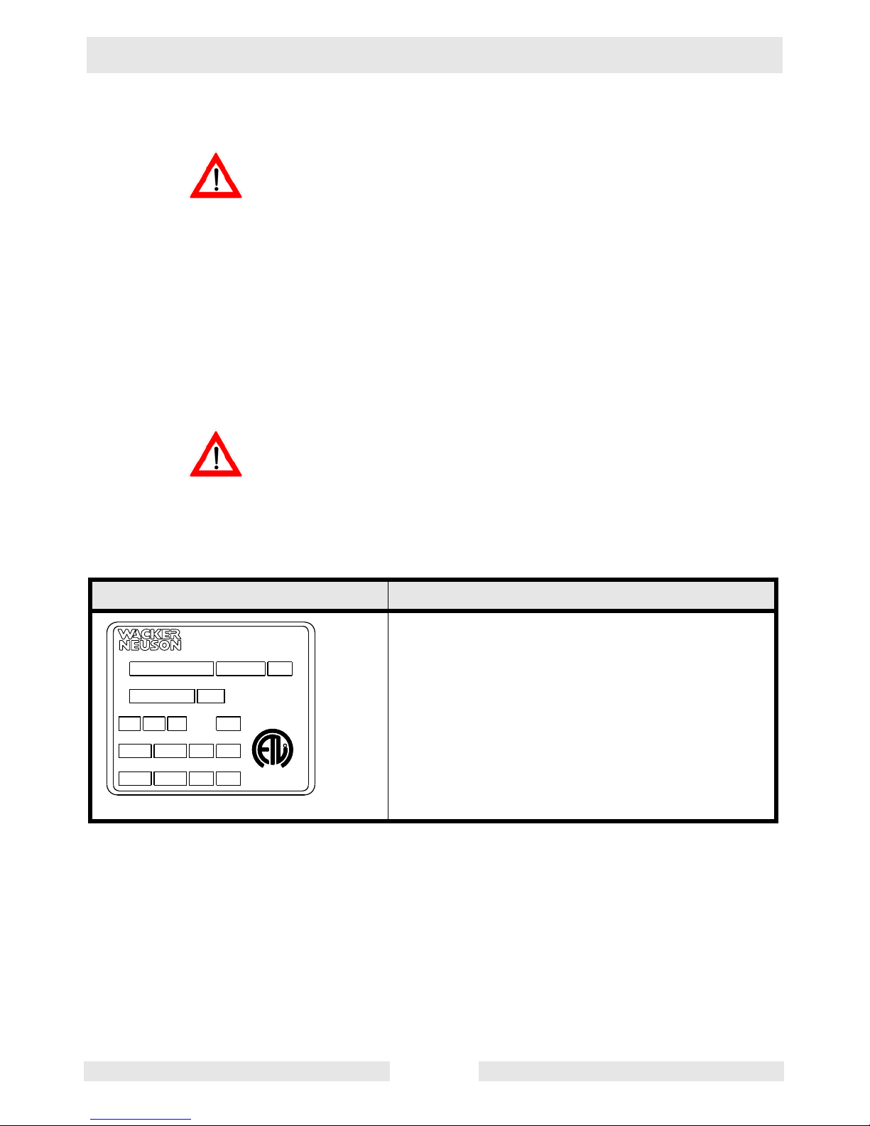
1.2 Information Labels
Label Meaning
Wacker Neuson Corporation
Model Item No. Rev.
Serial No.
VHz
Phase
Menomonee Falls, WI 53051 USA
Man. Y/M
THERMALLY PROTECTED
INDOORS OR OUTDOORS
CSA ENCLOSURE 3
Amp.
Conforms to UL Std. 778
Cert. to CAN/CSA St d.
kWkgMax. L/minMax. m
HPlbsMax. GPMMax. ft
CUS
MADE IN TAIWAN
C22.2 No. 108-M89
L
I
S
2001993
A nameplate listing the model number, item
number, revision number, and serial number is
attached to each unit. Please record the
information found on this plate so it will be
available should the nameplate become lost or
damaged. When ordering parts or requesting
R
D
E
T
service information, you will always be asked to
specify the model number, item number, revision
number, and serial number of the unit.
wc_si000249gb.fm 6
Page 7
PSG2 500 Operation
2. Operation
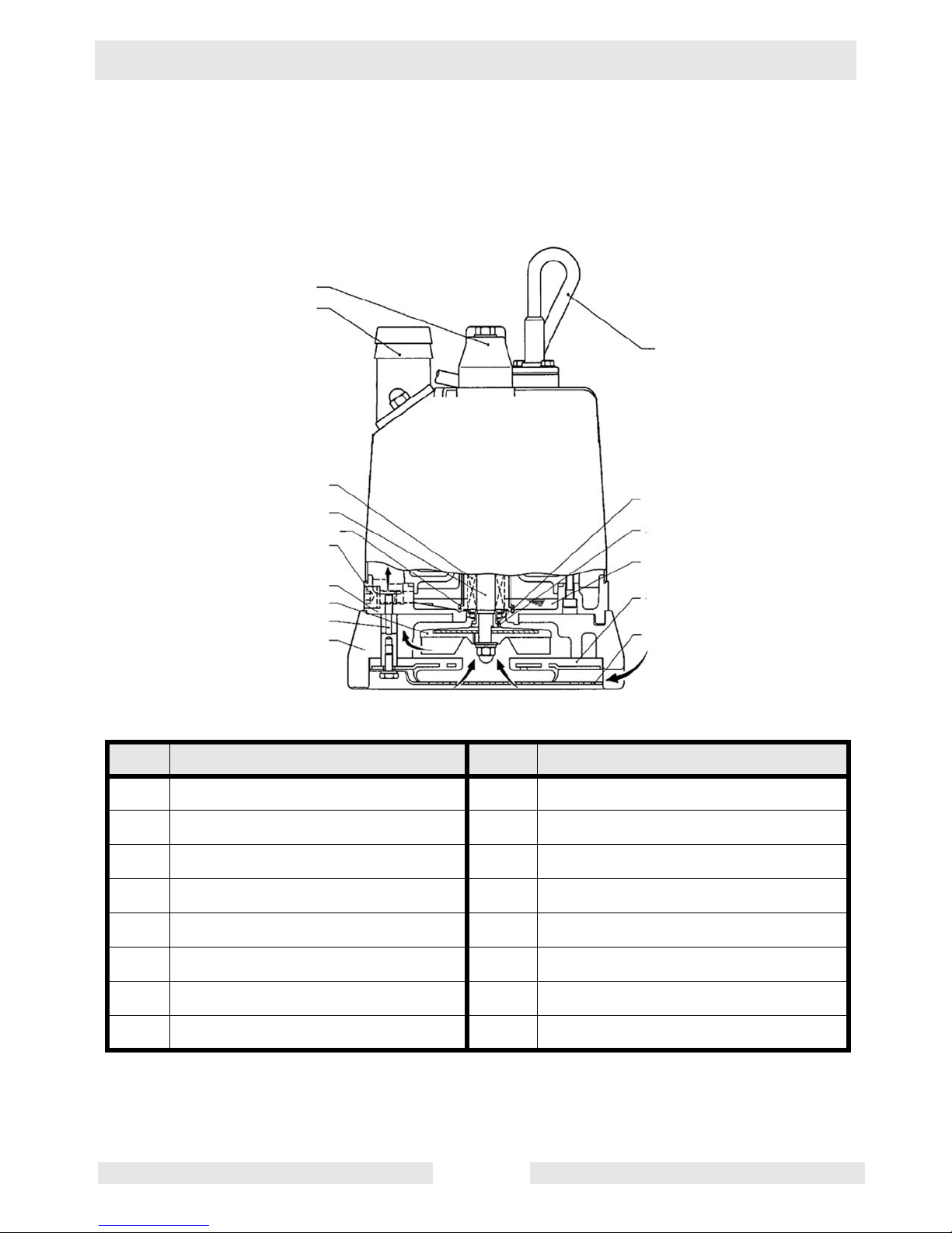
2.1 Names of Parts
See Graphic: wc_gr004637
1
2
7
8
10
3
4
12
14
15
16
wc_gr004637
Ref. Description Ref. Description
1 Lifting handle 9 Lubricant
2 Coupling 10 Shaft
3 Oil lifter 11 Shaft sleeve
4 Oil plug 12 Oil casing
5 Suction cover 13 V-ring
13
11
9
5
6
6 Strainer 14 Impeller
7 Cable assembly 15 Stud bolt
8 Mechanical seal 16 Pump casing
wc_tx000820gb.fm 7
Page 8
Operation PSG2 500
2.2 Prior to Operation
When the pump is delivered, first perform the following checks:
• Inspection
While unpacking, inspect the product for damage during shipment, and
make sure all bolts and nuts are tightened properly.
• Specification check
Check the model number to make sure it is the product that was
ordered. Be certain it is the correct voltage and frequency.
Note: If there is any problem with the product as shipped, contact your
nearest dealer or Wacker Neuson representative at once.
• Product specifications
Do not operate this product under any conditions other than those for
which it is specified. Failure to observe this precaution can lead to
CAUTION
electrical shock, current leakage, fire, water leakage or other
problems.
2.3 Installation
If the pump is used for outdoor fountains, garden ponds and similar
places, or to drain a swimming pool, the pump must be supplied by an
isolating transformer or connected to a Residual Current Device (RCD)
WARNING
with a residual operating current not exceeding 30 mA.
The pump must not be used when people are in the water.
Leakage of pump lubricants may cause pollution of water.
Proper plug must be provided according to local codes and standards.
Refer to wiring diagram.
DO NOT use this pump in liquids other than water, such as oil, salt
water, or organic solvents.
Use with a power supply voltage within ±5% of the rated voltage.
DO NOT use in water temperatures outside the range of 0–40°C (32–
104°F) which can lead to failure, electrical leakage or shock.
DO NOT use in the vicinity of explosive or flammable materials.
Use only in fully assembled state.
Note: Consult your local dealer or Wacker representative before using
with any liquids other than those indicated in this manual.
wc_tx000820gb.fm 8
Page 9
PSG2 500 Operation
Preparing for installation
Before installing the pump at a work site, you will need to have the
following tools and instruments ready:
• Insulation resistance tester (megohmmeter)
• AC voltmeter
• AC ammeter (clamp-on type)
• Bolt and nut tighteners
• Power supply connection tools (screwdriver or box wrench)
Note: Please also read the instructions that come with each of the test
instruments.
Checks to make before installation
• When a grounded plug is used:
Use the megohmmeter to measure the insulation resistance between
the cable assembly prongs and ground.
• When connection leads are used:
WARNING
CAUTION
With the megohmmeter, measure the insulation resistance between
each core lead and the ground lead.
Reference insulation resistance: 20MW or greater
Note: The reference insulation resistance (20MW or greater) is the
value when the pump is new or has been repaired. For the reference
value after installation, see “Maintenance and Inspection.”
Precautions During Installation
Do not under any circumstances install or move the pump by
suspending it from the cable assembly. The cable may be damaged,
causing electrical leakage, shock, or fire.
When installing the pump, pay close attention to its center of gravity
and weight. If it is not lowered into place correctly, it may fall and be
damaged or cause injury.
When transporting the pump by hand, be sure to employ manpower
commensurate with the weight of the pump. To avoid back injury when
lifting the pump, bend the knees to pick it up rather than bending your
back only.
2.3.1 Avoid dropping the pump or other strong impact. Lift the pump by
holding it firmly with the hands or by attaching a rope or chain to the
handle.
Note: On cable assembly handling, see Electrical Wiring.
2.3.2 Install the pump in a location with sufficient water level, where water
collects readily.
wc_tx000820gb.fm 9
Page 10
Operation PSG2 500
Note: See “Operating water level” for the water level necessary for
operation. The discharge end of the hose should be located higher
than the water surface. If the end of the hose is submerged, water may
flow back to the pump when the pump is stopped; and if the hose end
is lower than the water surface, water may overflow when the pump is
turned off.
2.3.3 The hose should be run as straight as possible, since excessive
bending will hinder the water flow, preventing sufficient lift, and can
even cause the hose to become clogged with earth. If the hose is
crimped near the pump, air can become trapped in the pump and
cause idle running.
If large quantities of earth are sucked up, damage resulting from
friction in the pump can lead to electrical leakage and shock.
CAUTION
2.3.4 Use the pump in the upright position. If there is a risk of the pump
drawing in debris or sediment, operate the pump inside a basket or by
enclosing it in a net.
2.3.5 If used in a permanent installation, where the pump is not readily
accessible after installation, please contact Wacker for a duplicate
nameplate to be installed at the wellhead or on the control box so that
it will be readily visible.
2.4 Electrical Wiring
Performing electrical wiring
Electrical wiring should be performed by a qualified person in accord
with all applicable regulations. Failure to observe this precaution not
WARNING
only risks breaking the law but is extremely dangerous.
Incorrect wiring can lead to current leakage, electrical shock or fire.
ALWAYS make sure the pump is equipped with the specified overload
protectors and fuses or breakers, so as to prevent electrical shock from
a current leak or pump malfunction.
Operate within the capacity of the power supply and wiring.
Grounding
DO NOT use the pump without first grounding it properly. Failure to
ground it can lead to electrical shock from a current leak or pump
WARNING
malfunction.
CAUTION
wc_tx000820gb.fm 10
Page 11
PSG2 500 Operation
DO NOT attach the grounding wire to a gas pipe, water pipe, lightning
arrester or telephone grounding wire. Improper grounding can result in
electrical shock.
Connecting the power supply
Before connecting leads to the terminal strip, make certain the power
supply is turned off (circuit breaker, etc.), to avoid electrical shock,
WARNING
shorting, or unexpected starting of the pump, leading to injury.
Before inserting the power supply plug, make certain the power supply
is turned off (circuit breaker, etc.), to avoid electrical shock, shorting,
or unexpected starting of the pump, leading to injury.
Do not use the pump with the cable assembly or plug connected
loosely, which can result in electric shock, shorting, or fire.
CAUTION
Draw power from a dedicated power outlet rated at 15 A or above.
Sharing the outlet with other equipment may cause overheating at the
branch outlet and could result in fire.
NOTICE: Be sure to use a dedicated power supply with a ground
leakage circuit breaker.
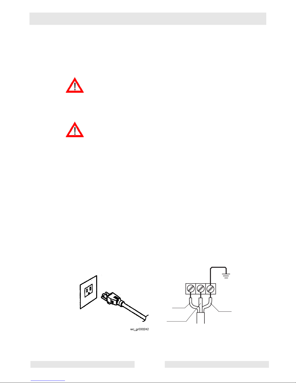
Grounded plug
Connect only to receptacle of proper voltage and current rating
matching that of the plug provided with the cable assembly.
Without Plug
Tighten the ends of the cable assembly securely against the terminal
board. If installation of a grounded plug is required, use only a properly
rated and approved CEE plug and secure the ends of the cable
assembly securely to power and ground terminals in accordance with
the plug manufacturer’s instructions.
See Graphics: wc_gr000242 and wc_gr004659
wc_tx000820gb.fm 11
RD
WH
L1
L2
G
GR
wc_gr004659
Page 12

Operation PSG2 500
Cable Assembly
If it is necessary to extend the cable assembly, use a core size equal
to or larger than the original. This is necessary not only to avoid a
CAUTION
performance drop, but to prevent cable overheating which can result in
fire, electrical leakage or electrical shock.
If a cable with cut insulation or other damage is submerged in the
water, there is a danger of damage to the pump, electrical leakage,
electrical shock, or fire.
Be careful not to let the cable assembly be cut or become twisted. This
may result in damage to the pump, electrical leakage, electrical shock,
or fire.
If it is necessary to submerge the connection wires of the cable
assembly in water, first seal the wires completely in a molded
protective sleeve, to prevent electrical leakage, electrical shock, or fire.
DO NOT allow the cable assembly wires or power supply plug to
become wet.
Make sure the cable does not become excessively bent or twisted, and
does not rub against a structure in a way that might damage it.
If used in a deep-well installation, the cable assembly should be
secured every twenty feet.
wc_tx000820gb.fm 12
Page 13
PSG2 500 Operation
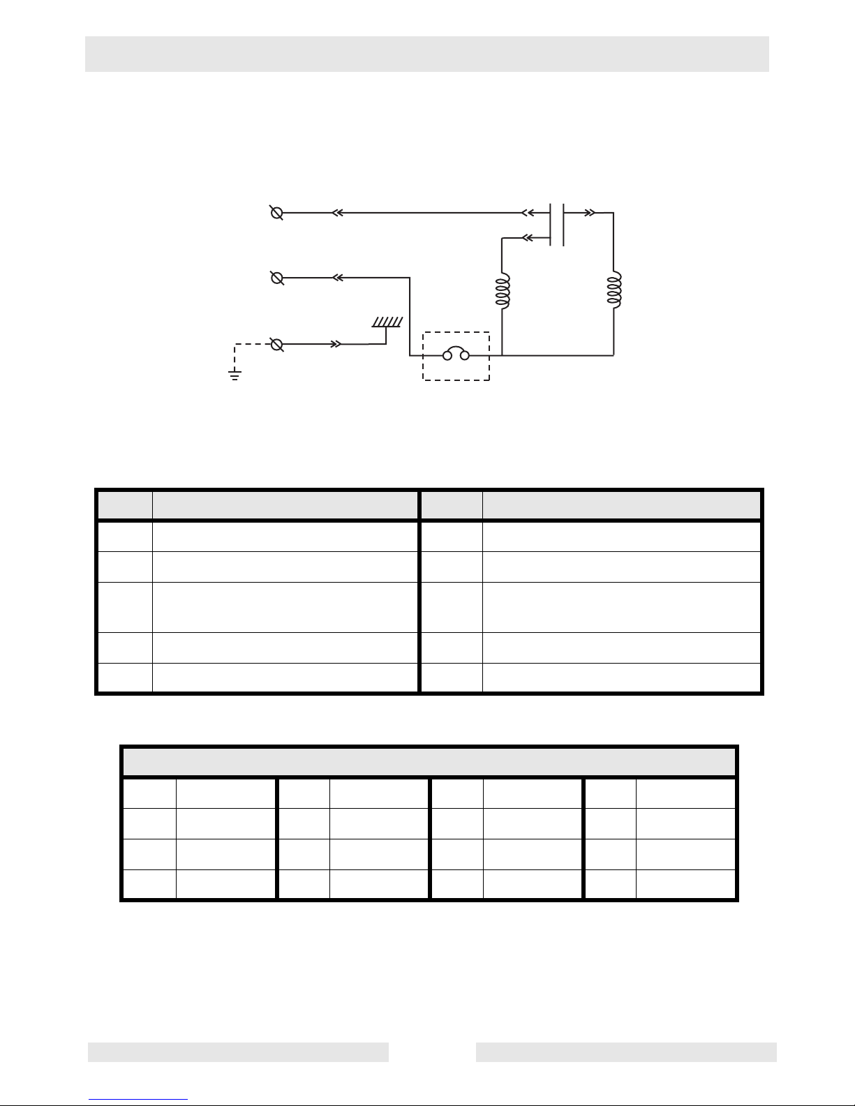
2.5 Wiring Diagram
See Graphic: wc_gr004640
RD
WH
GN GN
6
RD
BK
WH
2
5
4
1
BU
3
wc_gr004640
Ref. Description Ref. Description
1 Capacitor 6 Ground
2 Main coil 7 Circle thermal protector
3 Auxiliary coil 8 Float switch (normally open
contact)
4 Miniature protector 9 Heater
5 Frame grounding
Wire Colors
BK Black RD Red YL Yellow OR Orange
GN Green TN Tan BR Brown PU Purple
BU Blue VIO Violet CL Clear SH Shield
PK Pink WH White GY Gray LB Light blue
wc_tx000820gb.fm 13
Page 14

Operation PSG2 500
2.6 Operation
Before starting
2.6.1 Make sure once again that the product is of the correct voltage and
frequency rating.
NOTICE: Using the product at other than rated voltage and frequency
will not only lower its performance but may damage the product.
Note: Confirm the rated voltage and frequency on the model
nameplate.
2.6.2 Confirm the wiring, supply voltage, circuit breaker capacity, and motor
insulation resistance.
Reference insulation resistance = 20 MΩ or greater.
Note: The reference insulation resistance (20 MΩ or greater) is the
value when the pump is new or has been repaired. For the reference
value after installation see Maintenance and Inspection.
2.6.3 The setting on the circuit breaker or other overload protector should be
made in accord with the rated current of the pump.
Note: See Operating Specifications for the rated current of the pump.
2.6.4 When powering the pump with a generator, be certain the generator is
sized to supply the required power for the pump and any other
equipment powered by the generator.
If the power source is protected by a fuse, use a time-delay fuse with
this pump.
CAUTION
Test Operation
NEVER operate the pump while it is suspended in the air. The recoil
may result in injury or other major accident.
WARNING
NEVER start the pump when people are standing next to it. A current
leak can result in electrical shock.
WARNING
Run the pump for a short time (3–10 minutes) and confirm the
following:
• Using an ammeter (clamp-on type), measure the operating
current at the L1 and L2 phase wires on the terminal.
COUNTERMEASURE: If the operating current exceeds the rated
value, pump motor overload may be a cause. Make sure the pump has
been installed under proper conditions as described in Installation.
• Using an AC voltmeter (tester), measure voltage at the terminals.
Supply voltage tolerance: within ±5% of rated voltage.
wc_tx000820gb.fm 14
Page 15

PSG2 500 Operation
COUNTERMEASURE: If the supply voltage is outside the tolerance,
possible causes are the power supply capacity or an inadequate
extension cable. Look again at the wiring diagram and make sure the
conditions are proper.
In case of very excessive vibration, unusual noise or odor, turn off the
power immediately and consult your nearest dealer or Wacker
CAUTION
WARNING
representative. Continuing to operate the pump under abnormal
conditions may result in electrical shock, fire, or current leakage.
Operation
Make sure no extraneous objects such as pins, nails or other metal
objects are sucked into the pump. These can damage the pump or
cause it to malfunction, and can result in electrical shock or electrical
leakage.
When the pump is not used for an extended period, be sure to turn off
the power (circuit breaker, etc.). Deterioration of the insulation may
lead to electrical leakage, electrical shock, or fire.
In case of a power outage, turn off the power to the pump to avoid
having it start unexpectedly when the power is restored, presenting
serious danger to people in the vicinity.
CAUTION
WARNING
The pump may become hot during operation. Do not touch an
operating pump. Allow the pump to cool before handling.
Pay careful attention to the water level while the pump is operating. Dry
operation may cause the pump to malfunction.
Note: See section Operating water level, for the water level necessary
for operation.
If the protection system operates due to an overload or malfunction,
causing the pump to stop, disconnect the power supply to the pump.
Make sure that the power is completely shut off before proceeding.
Next, unplug the cable assembly from the receptacle or detach it from
the terminals. Then, investigate and remove the cause of the
malfunction before restarting the pump.
wc_tx000820gb.fm 15
Page 16

Operation PSG2 500
Operating water level
Do not operate the pump below the C.W.L. (Continuous running Water
Level) indicated below. Failure to observe this condition may result in
CAUTION
See Graphic: wc_gr004663
damage to the pump, current leakage or electrical shock.
5 mm
(0.20")
wc_gr004663
wc_tx000820gb.fm 16
Page 17

PSG2 500 Maintenance
3. Maintenance
3.1 Periodic Maintenance Table
Pump
Measure insulation resistance.
Reference insulation resistance =
1MW or greater. (1)
Measure operating current.
Compare with rated current.
Measure supply voltage.
Compare with allowable range (within ±5%
of rated voltage).
Pump inspection.
A noticeable drop in performance may indicate a worn or clogged impeller, strainer,
etc. Remove the clogged debris and replace
any worn parts.
Lubricant inspection. (2)
Weekly
Monthly
Every
1000
hrs.
Every
2000
hrs.
Every
4000
hrs.
Change lubricant. (2)
(Designated lubricant: SAE 10W/20W, Tur-
bine Oil ISO VG32 or equivalent)
Change mechanical seal. (3)
Overhaul.
This should be carried out even if there are
no problems with the pump. The frequency
depends on how continuously the pump is
in use. (4)
(1) If the insulation resistance has become noticeably lower than the previous inspection, an inspec-
tion of the motor will be necessary.
(2) See Inspecting Lubricant and Replacing Lubricant in this chapter.
(3) Specialized know-how is required for inspecting and replacing the mechanical seal. Consult your
nearest dealer or Wacker representative.
(4) Consult your nearest dealer or Wacker representative regarding overhauls.
wc_tx000821gb.fm 17
Page 18

Maintenance PSG2 500
3.2 Maintenance and Inspection
Regular maintenance and inspections are a necessity for continued
efficient functioning of the pump. If any abnormal conditions are
noticed, refer to the Troubleshooting section and take corrective
measures immediately. It is recommended that a spare pump be kept
ready in case of any problems.
Prior to inspecting
Before inspecting the pump, make certain the power supply (circuit
breaker, etc.) is turned off. Then, unplug the cable assembly from the
WARNING
3.2.1 Washing the pump
3.2.2 Inspecting the pump exterior
receptacle or detach it from the terminals. Failure to follow this
precaution may result in a serious accident from electrical shock or
unexpected starting of the pump motor.
Remove accumulated matter from the surface of the pump and wash
it with clean water. Take special care to remove any debris from the
impeller.
Look for any peeling or chipped paint, and make sure the nuts and
bolts are fastened tightly. Any cracks in the surface should be repaired
by cleaning that area, drying it and then applying a touch-up coating.
Note: Touch-up paint is not supplied. Note that some kinds of damage
or looseness may require that the unit be disassembled for repairs.
Please consult your nearest dealer or Wacker representative.
Storage
When the pump is out of use for an extended period, wash it and dry it
thoroughly, then store it indoors.
Note: Always run a test operation before putting the pump back into
service.
If the pump is left in the water, it should be run a minimum of once a
week.
• Inspecting Lubricant
Remove the oil plug and tilt the pump to drain a small amount of
lubricant. If the lubricant is milky white or has water mixed in with it, the
mechanical seal may be faulty. In this case the pump will need to be
disassembled and repaired.
• Replacing Lubricant
Remove the oil plug and drain all the lubricant, then replace it with the
specified amount.
wc_tx000821gb.fm 18
Page 19

PSG2 500 Maintenance
Note: Worn lubricant and other waste products should be disposed of
by a qualified agent, in accord with applicable laws. The oil plug gasket
should be replaced each time the lubricant is inspected or changed.
See Graphic: wc_gr004661
1
2
1
2
3
4
3
wc_gr004661
Ref. Description Ref. Description
1. Oil inlet 3. Oil plug
2. Gasket 4. Allen wrench
Pump Model Lubricant Capacity
PSG2 500 150 ml (5.1 fl. oz.)
Replacement Parts
The table lists the parts that need to be replaced periodically. Replace
these using the recommended frequency as a guideline.
Part Replacement Frequency
Mechanical seal When lubricant in oil compartment becomes milky.
Lubricant (SAE 10W/20W or
Every 2,000 hours or 12 months, whichever comes first.
equivalent)
Packing and O-ring Each time pump is disassembled or inspected.
Sleeve When it becomes worn.
V-ring When it becomes worn, or each time the pump is disas-
wc_tx000821gb.fm 19
sembled or inspected.
Page 20

Maintenance PSG2 500
3.3 Disassembly/Reassembly
Before disassembling the pump, make certain the power supply (circuit
breaker, etc.) is turned off. Then, unplug the cable assembly from the
WARNING
receptacle or detach it from the terminals. To avoid electrical shock,
DO NOT work with wet hands.
NEVER check the operation of any parts (impeller rotation, etc.) by
turning on the power while the unit is partially assembled. Failure to
observe these precautions may result in a serious accident.
DO NOT disassemble or repair any parts other than those designated
here. If repairs are necessary in any other than the designated parts,
consult your nearest dealer or Wacker representative. Improper
repairs can result in electrical leakage, electrical shock, fire, or water
leaks.
After reassembly, ALWAYS perform a test operation before resuming
use of the pump. Improper assembly will cause the pump to
malfunction, resulting in electric shock or water leaks.
The procedure for disassembly and reassembly is shown here to the
extent necessary for impeller replacement. A specialized environment
and facilities are necessary for work on the mechanical seal and the
motor parts. Contact your nearest dealer or Wacker representative in
the event such repairs are necessary.
wc_tx000821gb.fm 20
Page 21

PSG2 500 Maintenance
3.4 Disassembly
See Graphic: wc_gr004650
Note: To enhance serviceability, the PSG2 500 has been designed so
that the entire pump portion illustrated below can be disassembled with
a 12mm box wrench.
.
Stand the pump upside down with the discharge connection facing
downward during disassembly and reassembly. Exercise care to
CAUTION
3.4.1 Remove the three hex bolts with washers (1), then remove the strainer
3.4.2 Remove the hex nut / spring / washer assembly (4).
3.4.3 Remove the impeller (5), pump casing (6), shaft sleeve (7), and the V-
prevent the pump from tipping, which may lead to injury..
(2) and suction cover (3).
ring (8).
.
WARNING
2
3
A worn impeller may have sharp edges that can cause injury, and
should be handled with care.
1
4
5
6
7
8
wc_tx000821gb.fm 21
wc_gr004650
Page 22

Maintenance PSG2 500
3.5 Reassembly
See Graphic: wc_gr004650, wc_gr004651
The reassembly procedure is in the reverse sequence of disassembly.
3.5.1 Remove sand and other debris from the impeller (5), pump casing (6)
and suction cover (3) before reassembly.
3.5.2 Install the V-ring (8) on the outside of the shaft sleeve (7). During the
installation, be careful not to apply oil to the area in which the V-ring
contacts the shaft sleeve.
3.5.3 During assembly of the pump casing, make sure to press it firmly
against the contact surface. The flange portion on the inside of the oil
casing (9) has four tabs. Make sure to firmly press the pump casing
until it engages the tabs.
3.5.4 Replace the packing with a new part. Replace all other worn or
damaged parts. Contact your Wacker representative for replacement.
3.5.5 After installing the impeller, make sure that it rotates smoothly.
a
b
wc_tx000821gb.fm 22
Page 23

PSG2 500 Maintenance
3.6 Troubleshooting
Before ordering repairs, carefully read through this manual, then
repeat the inspection. If the problem remains, contact your nearest
dealer or Wacker representative.
ALWAYS turn off the power before inspecting the pump. Failure to
WARNING
observe this precaution can result in serious accident.
Problem / Symptom
Pump will not start
Pump stops soon after start-
ing (Motor protector operates)
Reason / Remedy
• Power is off. Restore power.
• Cable assembly is cut or not connected properly. Repair/
replace the cable or fix the connection.
• Plug is not inserted. Connect the plug.
• Impeller is clogged. Inspect the pump and remove any
debris.
• Start float does not operate. Remove any obstruction
and check the float operation.
• Impeller is clogged. Remove debris.
• Low voltage. Provide the rated voltage, or make sure the
cable assembly extension is the proper standard.
• Wrong power frequency. Check the nameplate, and
replace the pump or the impeller.
• Extended operation with a clogged strainer. Remove
debris from the strainer.
• Faulty motor (burning, water infiltration, etc.). Repair or
replace the motor.
• Motor protection system was triggered. Identify and correct cause before re-starting.
Poor lift or discharge
capacity
Heavy vibration or noise
Pump will not stop automati-
cally
wc_tx000821gb.fm 23
• Worn out impeller or suction cover. Repair or replace the
worn parts.
• Sharply bent or clogged hose. Straighten out any sharp
bends. Enclose the pump with a screen to keep away
debris.
• Strainer clogged or buried. Remove debris from the
strainer, or place a block under the pump.
• Wrong power frequency. Check the nameplate, and
replace the pump or the impeller.
• Damaged motor shaft. Contact dealer and replace
motor.
• Something is interfering with the float operation, or the
float switch is faulty. Remove any obstacles, or replace
the switch.
Page 24

Maintenance PSG2 500
Notes
wc_tx000821gb.fm 24
Page 25

PSG2 500 Technical Data
4. Technical Data
4.1 Standard Specifications
Model: PSG2 500 BOM: 0620412
Applicable liquids,
consistency and
temperature
Rain water, fountain water, ground water,
muddy water
0–40°C (32–104°F)
Pump Impeller Semi-vortex type
Shaft seal Double mechanical seal
Bearing Shielded ball bearing
Motor Specification Dry submersible induction motor (2-pole)
Insulation Class E
Protection system Miniature protector
Lubricant SAE 10W/20W
Connection Hose coupling (NPT male thread)
wc_td000252gb.fm 25
Page 26

Technical Data PSG2 500
4.2 Operating Specifications (60 Hz)
Model: PSG2 500 BOM: 0620412
Pump
Electric power
Rated current
Starting
V/Ph/Hz
110/1/60
A
6.1
Capacitor-run
method
Discharge
Output
Max. head
Max. capacity
Max. pressure
Solid size
mm (in.)
kW (Hp)
m (ft.)
L/min
(GPM)
kg/cm
(psi)
mm (in.)
50 (2-inch NPT)
0.48 (2/3)
12 (39.5)
240 (62)
2
1.19 (17)
6 (0.2)
capacity
Weight*
* The weight (mass) given above is the operating weight of the pump itself, not including the cable
assembly.
Kg (lbs.)
10.5 (23)
wc_td000252gb.fm 26
Page 27

PSG2 500 Technical Data
4.3 Dimensions
mm (in.)
231 (9.13)
210 (8.25)
174 (6.81)
285 (11.19)
271 (10.69)
210 (8.25)
5 (0.20)
228 (9)
wc_gr004656
wc_td000252gb.fm 27
Page 28

Page 29

Page 30

Page 31

Page 32

Page 33

Page 34

Page 35

Page 36

Page 37

Page 38

Page 39

Page 40

Page 41

Page 42

Wacker Construction Equipment AG · Preußenstraße 41 · D-80809 München · Tel.: +49-(0)89-3 54 02 - 0 · Fax: +49 - (0)89-3 54 02-3 90
Neuson Corporation · P.O. Box 9007 · Menomonee Falls, WI 53052-9007 · Tel. : (262) 255-0500 · Fax: (262) 255-0550 · Tel. : (800) 770-0957
Wacker
Wacker Asia Pacific Operations · Skyline Tower, Suite 2303, 23/F · 39 Wang Kwong Road, Kowloon Bay, Hong Kong · Tel. +852 2406 60 32 · Fax: +852 2406 60 21
 Loading...