

Page 1

Pump
PS (3-Phase)
Series
OPERATOR’S MANUAL
0154626en 002
0409
0154626EN
Page 2

Page 3

PS (3-Phase) Series Table of Contents
wc_bo0154626002enTOC.fm 1
1. Foreword 3
2. Safety Information 4
2.1 Operating and Electrical Safety ............................................................ 5
2.2 Information Labels ................................................................................ 5
3. Technical Data 6
3.1 Standard Specifications ........................................................................ 6
3.2 Operating Specifications (50 Hz) .......................................................... 7
4. Operation 11
4.1 Names of Parts ................................................................................... 11
4.2 Prior to Operation ............................................................................... 12
4.3 Installation .......................................................................................... 13
4.4 Electrical Wiring .................................................................................. 16
4.5 Operation ............................................................................................ 19
5. Maintenance 23
5.1 Periodic Maintenance Schedule ......................................................... 23
5.2 Maintenance and Inspection .............................................................. 24
5.3 Disassembly and Reassembly ........................................................... 26
5.4 Troubleshooting .................................................................................. 33
Page 4

Table of Contents PS (3-Phase) Series
wc_bo0154626002enTOC.fm 2
Page 5

Foreword
wc_tx000001gb elec tr ic. fm 3
1. Foreword
This manual provides information and procedures to safely operate
and maintain this Wacker m odel. For you r own safet y and prote ction
from injury, carefully read, understand and observe the safety
instructions described in this manual.
Keep this manual or a copy of it with the machine. If you lose this
manual or need an additional copy, please contact Wacker
Corporation. This machine is built with user safety in mind; however,
it can present hazards if improperly operated and serviced. Follow
operating instructions carefully! If you have questions about operating
or servicing this equipment, please contact Wac ker Corporation.
The information contained in this manual was based on machines in
production at the time of publication. Wacker Corporation reserves the
right to change any portion of this information without notice.
All rights, especially copying and distribution rights, are reserved.
Copyright 2007 by Wacker Corporation.
No part of this publication may be reproduced in any form or by any
means, electronic or mechanical, including photocopying, without
express written permission fr om Wacker Co rp or at io n.
Any type of reproduction or distribution not authorized by Wacker
Corporation represents an infringement of valid cop y rights and will be
prosecuted. We expressly reserve the right to make technical
modifications, even without due notice, which aim at improving our
machines or their safety standards.
Page 6
Safety Information PS 3-Phase Series
wc_si000041gb.fm 4
2. Safety Information
This manual contains DANGER, WARNING, CAUTION, and NOTE
callouts which must be followed to reduce the possibility of personal
injury, damage to the equipment, or improper service.
This is the safety alert symbol. It is used to alert you to potential
personal injury hazards. Obey all safety messages that follow this
symbol to avoid possible injury or death.
DANGER indicates an imminently hazardous situation which, if not
avoided, will result in death or serious injury.
WARNING indicates a potentially hazardous situation which, if not
avoided, could result in death or serious injury.
CAUTION indicates a potentially hazardous situation which, if not
avoided, may result in minor or moderate injury.
CAUTION: Used without the safety alert symbol, CAUTION indicates
a potentially hazardous situation which, if not avoided, may result in
property damage.
Note:
Contains additional information important to a procedure.
DANGER
WARNING
CAUTION
Page 7
PS 3-Phase Series Safety Information
wc_si000041gb.fm 5
2.1 Operating and Electrical Safety
To reduce risk of electric shock, connect only to a properly grounded,
grounding-type receptacle.
Risk of electric shock - This pump has n ot be en inve stigated for use i n
swimming pool areas.
An acceptable motor-control switch shall be provided at the time of
installation according to local codes and regulations.
To reduce risk of electric shock, see instruction manual for proper
installation.
CAUTION: This pump may automatically restart. Prior to working on
the pump or control panel all supply circuits must be disconnected.
CAUTION: Risk of shock - Do not remove cord and strain relief.
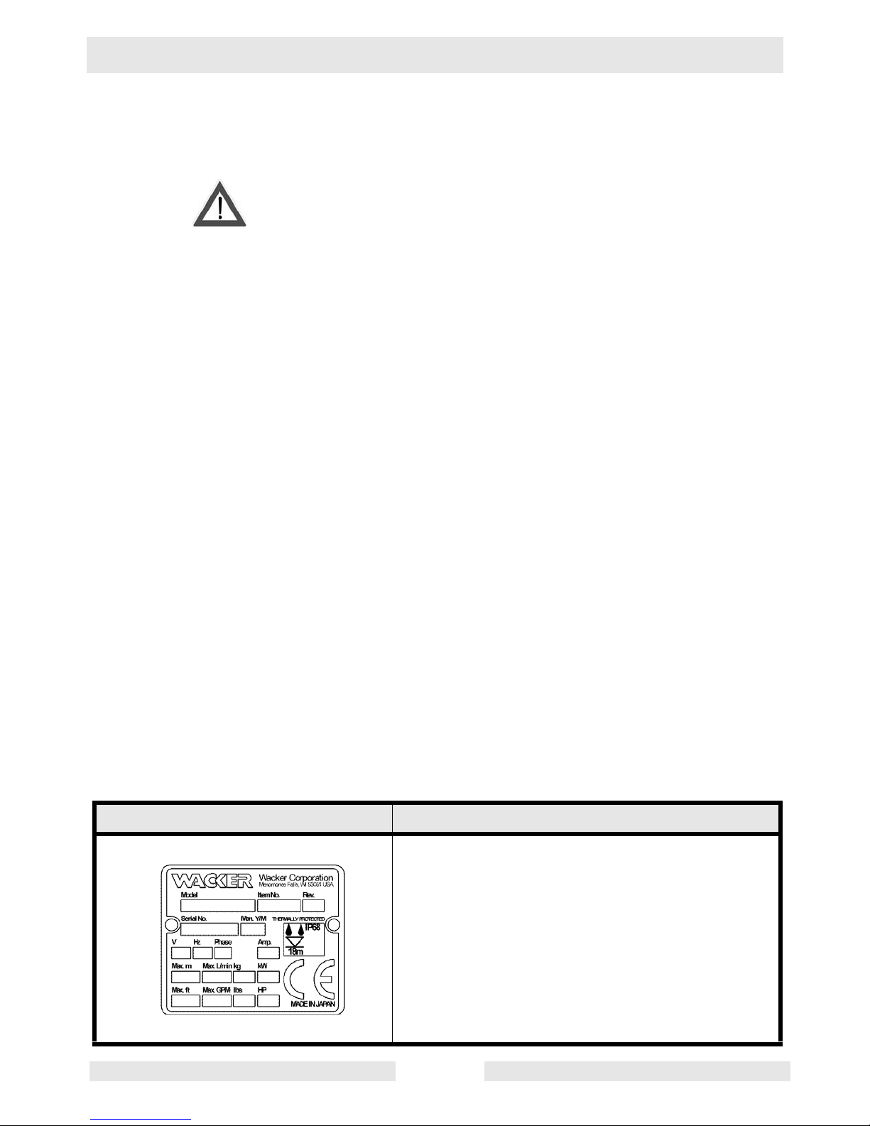
2.2 Information Labels
Label Meaning
A nameplate listing the Model Number, Item
Number, Revision, and Serial Number is
attached to each unit. Please record the information found on this plate so it will be available
should the nameplate become lost or damaged.
When ordering parts or requesting service information, you will always be asked to specify the
model, item number , revision number, and serial
number of the unit.
WARNING
Page 8

Technical Data PS (3-Phase) Series
wc_td000041gb.fm 6
3. Technical Data
3.1 Standard Specifications
Applicable Liquids,
Consistency and
Temperature
Work drainage and Sand-Carrying Water
0–40°C (32–104°F)
Pump Impeller Open Type
Shaft Seal Double Mechanical Seal
Bearing Shielded Ball Bearing
Motor Specification Dry Submersible Induction Motor (2-P ole)
Insulation Class B: 7.5 to 11 kW
Class E: 1.5 to 5.5 kW
Protection Sys tem Circle Thermal Protector
Lubricant SAE 10W/20W
Such as:
–Turbine Oil ISO VG #32
–Shell Victrolia Oil #27
–British Pet Energol THB #32
–Gulf Paramount #32
–Tellus #T22 Shell Oil
–Shell Turbo T32
Connection Coupling (Barb, BSP, QD)
Refer to BOM Product Matrix in Parts Section
Page 9
PS (3-Phase) Series Technical Data
wc_td000041gb.fm 7
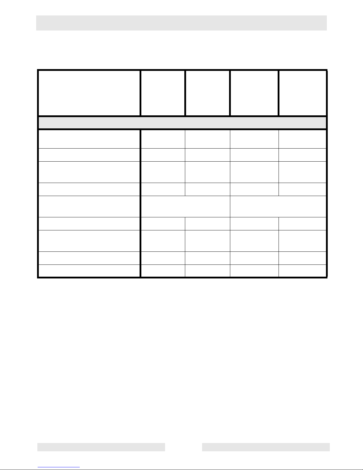
3.2 Operating Specifications (50 Hz)
*The weight (mass) given above is the operating weight of the pump itself, not including the cable
assembly.
PS 2 1503
0009186
0008801-
0008806
PS 3 1503
0009187
0009188
0008807-
0008812
PS 2 2203
0009189
0009190
0008813-
0008818
PS 3 2203
0009191
0009192
0008819-
0008824
Pump
Bore
mm
(in.)
50 (2) 80 (3) 50 (2) 80 (3)
Phase 3 3 3 3
Starting Method Direct
Online
Direct
Online
Direct Online Direct Online
Output
kW (Hp)
1.5 (2) 1.5 (2) 2.2 (3) 2.2 (3)
Rated Current
A
(V)
3.4
(400)
5.5
(400)
Maximum Head
m (ft.)
21.5 (71) 14.4 (47) 26 (85) 20.4 (67)
Maximum Capacity
L/min
(GPM)
430
(114)
670
(177)
500
(132)
800
(211)
Solid Size Capacity
mm (in.)
8.5 (0.3) 8.5 (0.3) 8.5 (0.3) 8.5 (0.3)
Weight*
Kg (lbs.)
29 (64) 29 (64) 32 (71) 32 (71)
Page 10

Technical Data PS (3-Phase) Series
wc_td000041gb.fm 8
*The weight (mass) given above is the operating weight of the pump itself, not including the cable
assembly.
PS 2 3703
0009193
0009194
0008825-
0008830
PS 3 3703
0009195
0009196
0008831-
0008836
PS 4 3703
0009197
0009198
0008837-
0008842
Pump
Bore
mm (in.)
50 (2) 80 (3) 100 (4)
Phase 3 3 3
Starting Method Direct Online Direct Online Direct Online
Output
kW (Hp)
3.7 (5) 3.7 (5) 3.7 (5)
Rated Current
A
(V)
7.5
(400)
Maximum Head
m (ft.)
36.5 (120) 29 (95) 18 (59)
Maximum
Capacity
L/min
(GPM)
450
(119)
900
(238)
1440
(380)
Maximum
Pressure
psi
50 44 26.4
Solid Size
Capacity
mm (in.)
8.5 (0.3) 8.5 (0.3) 8.5 (0.3)
Weight*
Kg (lbs.)
55 (121) 55 (121) 55 (121)
Page 11

PS (3-Phase) Series Technical Data
wc_td000041gb.fm 9
*The weight (mass) given above is the operating weight of the pump itself, not including the cable
assembly.
PS 3 5503
0009199
0009200
0008843-0008848
PS 4 5503
0009201
0009202
0008849-0008854
Pump
Bore
mm (in.)
80 (3) 100 (4)
Phase 3 3
Starting Method Direct Online Direct Online
Output
kW (Hp)
5.5 (7.5) 5.5 (7.5)
Rated Current
A
(V)
10.8
(400)
Maximum Head
m (ft.)
32 (105) 22.5 (74)
Maximum Capacity
L/min (GPM)
1100
(291)
1750
(462)
Maximum Pressure
psi
54 34.6
Solid Size Capacity
mm (in.)
8.5 (0.3) 8.5 (0.3)
Weight*
Kg (lbs.)
66 (146) 66 (146)
Page 12

Technical Data PS (3-Phase) Series
wc_td000041gb.fm 10
*The weight (mass) given above is the operating weight of the pump itself, not including the cable
assembly.
PS 4
7503HH
0009203
0009204
0008855-
0008860
PS 4
7503HF
0009205
0009206
0008861-
0008866
PS 4
11003HH
0009207
0009208
0008867-
0008870
0008876
0008877
PS 4
11003HF
0009209
0009210
0008871-
0008874
0008878
0008879
Pump
Bore
mm
(in.)
100
(4)
100 / 150
(4 / 6)
100
(4)
100 / 150
(4 / 6)
Phase 3 3 3 3
Starting
Method
Direct Online Direct Online Direct Online Direct Online
Output
kW (Hp)
7.5 (10) 7.5 (10) 11 (15) 11 (15)
Rated Current
A
(V)
14.3
(400)
21.0
(400)
Maximum
Head
m (ft.)
40 (131) 31 (102) 49 (159) 32.5 (107)
Maximum
Capacity
L/min
(GPM)
1400
(370)
2040
(539)
1440
(380)
2440
(645)
Maximum
Pressure
psi
60 44 73 46
Solid Size
Capacity
mm
(in.)
8.5
(0.3)
8.5
(0.3)
20
(0.8)
20
(0.8)
Weight*
Kg (lbs.)
93 (205) 93 (205) 130 (287) 130 (287)
Page 13
PS (3-Phase) Series Operation
wc_tx000123gb.fm 11
4. Operation
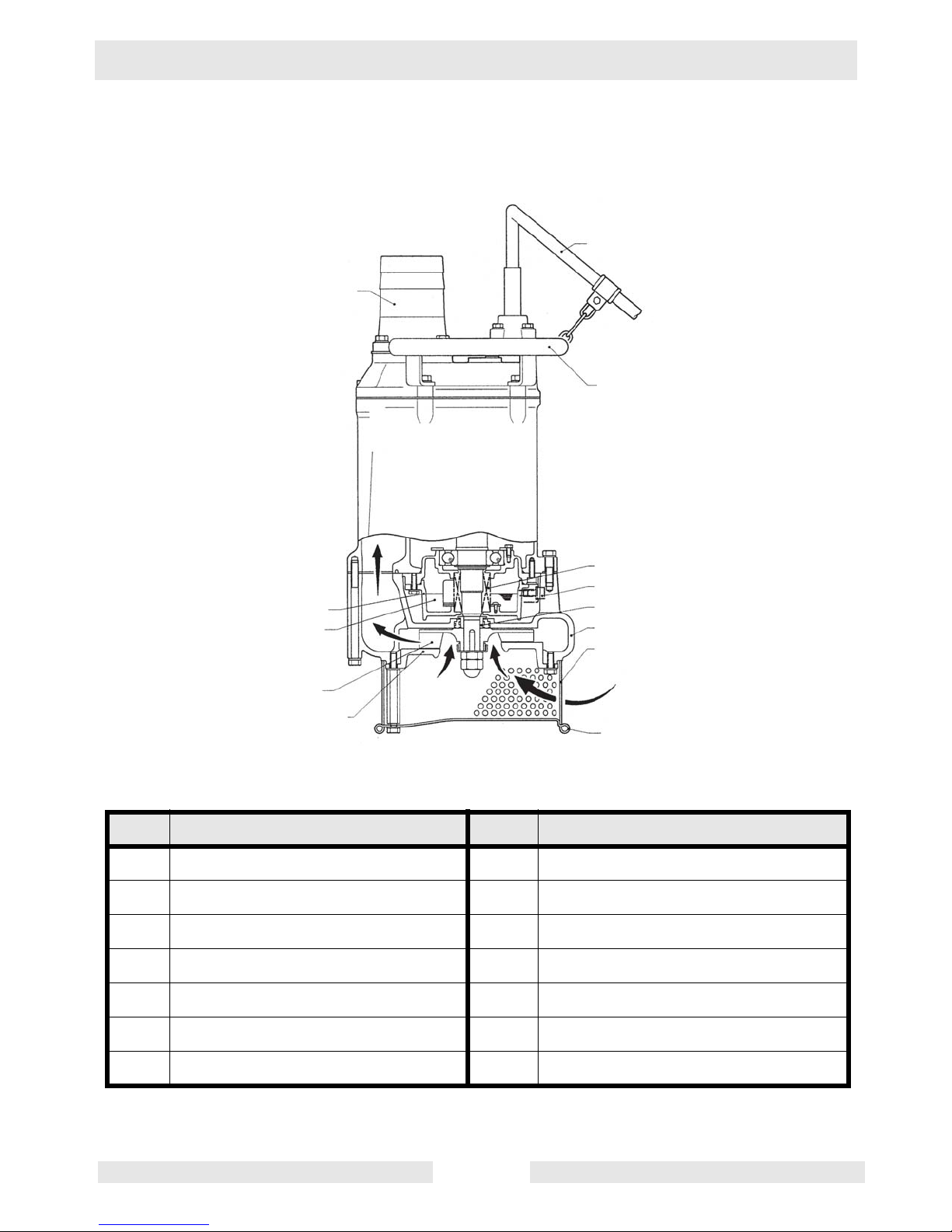
4.1 Names of Parts
See Graphic: wc_gr000327
Note:
This diagram shows the parts layout of a typical PS (Three-Phase) model. The external
appearance and the internal construction may vary slightly, depending on your particular model.
Ref. Description Ref. Description
1. Discharge Outlet 8. Lifting Handle
2. Coupling 9. Mechanical seal
3. Oil Housing 10. Oil plug
4. Lubricant 11. Sleeve
5. Impeller 12. Volute
6. Suction cover 13. Strainer
7. Cable Assem b ly 14. Plate
wc_gr000327
7
1
2
8
9
10
11
12
13
14
6
5
4
3
Page 14

Operation PS (3-Phase) Series
wc_tx000123gb.fm 12
4.2 Prior to Operation
When the pump is delivered, first perform the following checks:
• Inspection
While unpacking, inspect the product for damage during shipment, and
make sure all bolts and nuts are tightened properly.
• Specification check
Check the model number to make sure it is the product that was
ordered. Be certain it is the correct voltage and frequency.
Note:
If there is any problem wi th the product as sh ipped, contact yo ur
nearest dealer or Wacker representative at once.
• Product specifications
Do not operate this product under any conditions other than those for
which it is specified. Failure to observe this precaution can lead to
electrical shock, current leakage, fire, water leakage or other
problems.
CAUTION
Page 15
PS (3-Phase) Series Operation
wc_tx000123gb.fm 13
4.3 Installation
If the pump is used for outdoor fountains, garden ponds and similar
places, or to drain a swimming p ool, the pum p must be suppl ied my an
isolating transformer or connected to a Residual Current Device (RCD)
with a residual operating current not exceeding 30 mA.
The pump must not be used when people are in the water.
Leakage of pump lubricants may cause pollution of water.
Proper plug must be provided according to local codes and standards.
Refer to wiring diagram.
The supply voltage should be within ± 5% of the rated voltage.
DO NOT use in water temperatures outside the range of 0–40°C (32–
104°F), which can lead to failure, electrical leakage or shock.
The pump should be used only for pumping plain water. The pump
should not be used to pump fluids such as oil, salt water, or organic
solvents.
The pump must never be used to pump ex plosive liquids an d should
never be operated in an area where explosive elements might be
present.
The pump must not be used in a partially disassembled state.
Note:
Consult your local dea ler or Wacker r epresentative before usi ng
with any liquids other than those indicated in this document.
Critical Pressure
Do not use the pump i n an area whe re the water pressure exceeds t he
values given below , as it may dama ge the pump, or cause a short or
electrical shock.
Model Critical Pressure
PS2 1503
PS2 2203
PS2 3703
PS4 3703
PS4 5503
PS3 1503
PS3 2203
PS3 3703
PS3 5503
0.5 MPa (71 PSI)
– discharge pressure during use
= critical pressure
PS4 7503HH
PS4 11003HH
PS4 7503HF
PS4 11003HF
critical pressure = 0.5 MPa (71 PSI)
WARNING
CAUTION
Page 16

Operation PS (3-Phase) Series
wc_tx000123gb.fm 14
Checks to Make Before Installation
With the megohmmeter, measure the insulation resistance between
each of the power wires and grounding wire to verify the insulation
resistance of the motor.
Reference insulation resistance: 20MW or greater
Note:
The reference insulation resistance (20MW or greater) is the
value when the pump is new or has been repaired. For the reference
value after installation, see Maintenance and Inspection.
Preparing for Installation
Before installing the pump at a wo rk site, you will need to have the
following tools and instruments ready:
• Insulation resistance tester (megohmmeter)
• AC voltmeter
• AC ammeter (clamp-on type)
• Bolt and nut tighteners
• Power supply connection tools (screwdriver or box wrench)
Note:
Please also read the instructions that come with each of the test
instruments.
Precautions During Insta llation
When installin g the pump, pay close attention t o its center of gra vity
and weight. If it is not suspended properly, i t may fall and be da maged
or cause injury.
When transporting the pump manually, be sure to employ manpower
commensurate with the weight of the p ump. To avoid back injur y when
lifting the pump, bend the knees to pick it up rather than bending your
back only.
Do not under any circumstances install or move the pump by
suspending it from the cable assembly. The cable may be damaged,
causing electrical leakage, shock, or fire.
4.3.1 This pump series is offere d with a vari ety of discha rge fitti ngs. Plea se
refer to the BOM Product Matrix in the Par ts Section to identify the type
of discharge fitting used on your pump. Follow procedures noted
below to assure a proper discharge connection.
Threaded Discharge Fitting (BSP) –
Tighten hose coupling or discharge pipe securely and with proper
gaskets.
Quick Disconnect Coupling (QD) –
Assure coupling is tightened securely to pump discharge fitting and
WARNING
CAUTION
Page 17

PS (3-Phase) Series Operation
wc_tx000123gb.fm 15
companion coupling is securely fastened with proper gaskets.
Barbed Discharge Fitting (Barb) –
Place hose clamp over hose and push hose to the base of the
discharge fi tting. Tighten the hose clamp to secure the hose in place.
4.3.2 Avoid dropping the pump or other strong impact. Lift the pump by
holding it firmly with the hands or by attaching a wire rope (a) or chain
to the handle.
Note:
For proper pr oced ur es for handling the cable assembly, refe r to
Section Electrical Wiring in this manual.
Do not operate the pump dry. Doing so will prevent the pump from
attaining its fu ll pote ntial an d may a lso da mage t he pump and l ead to
a short and electrical shock.
In order to properly discharge water, provide adequate piping to the
area where the pump is mounted. Improper piping may lead to water
leakage or other m alfunctio ns.Install t he pump only in an area that can
maintain a proper water level.
4.3.3 Install the pump only in an area that can maintain a proper water level.
Note:
For details on the water level necessary for pump operation,
refer to “Water Level During Operation” in the Operation section.
4.3.4 When using a hose to provide piping to the pump, observe the
following:
Use the shortest possible length of discharge hose and minimize the
number of bends. Verify that the end of the hose (discharge side) is
lifted above the water surf ac e (a). If the end of the hose is submerged
in water, it may cause the water to flow back (b) when the pump has
been stopped. If the end of the hose is located at a level that is lower
than that of the source water surface, water may continue to flow out
even after the pump has been stopped.
Note:
Appropriate piping materials must be provided by the user.
Piping materials are not included with the product
..
If large quantities of sediment are drawn into the pump, damage
resulting from wear to the pump can lead to current leakage and
electrical shock.
4.3.5 Use the pump in the upright position. To prevent the pump from
becoming subme r ged in mud, mount it on a block or other firm base if
necessary.
4.3.6 If used in a permanent installation, where the pump is not readily
accessible after installation, please contact Wacker for a duplicate
nameplate to be install ed at th e w ell he ad o r on the cont ro l box so th at
it will be readily visible.
See Graphic: wc_gr000328, wc_gr000329, and wc_gr000330
CAUTION
CAUTION
Page 18

Operation PS (3-Phase) Series
wc_tx000123gb.fm 16
4.4 Electrical Wiring
Performing electrical wiring
Electrical wiring should be performed by a qualified person in accord
with all applicable regulations. Failure to observe this precaution not
only risks breaking the law but is extremely dangerous.
Incorrect wiring can lead to current leakage, electrical shock or fire.
ALWAYS make sure the pum p is equi pped w ith the specif ied ov erload
protectors and fuses or br eakers, so as to prevent electri cal shock from
a current leak or pump malfunction.
Operate within the capacity of the power supply and wiring.
Grounding
DO NOT use the p ump without first grou nding it properly. Fa ilure to
ground it can lead to electrical shock from a current leak or pump
malfunction.
DO NOT attach the gr ou nd ing wire to a g as p ipe, water pipe, li gh tni n g
arrestor or tele phone ground ing wire. Improper grounding ca n result in
electrical shock.
Cable Assembly
If it is neces sary t o ext end the c abl e ass embl y, us e a c ore size equal
to or larger than the original. This is necessary not only for avoiding a
performance drop, but to preven t cable overhea ting which can result in
fire, electrical leaka ge or ele ctr ical shock.
wc_gr000329
b
c
wc_gr000330
wc_gr000328
a
WARNING
WARNING
CAUTION
CAUTION
Page 19

PS (3-Phase) Series Operation
wc_tx000123gb.fm 17
If a cable with cut insulation or other damage is submerged in the
water, there is a danger of damage to the pump, electrical leakage,
electrical shock, or fire.
Be careful not to let the cable assemb ly be cut or become t wisted. Th is
may result in damage to the pump , electrical leak age, electrica l shock,
or fire.
If it is necessary to submerge the connection wires of the cable
assembly in water, first seal the wires completely in a molded
protective sleeve, to preve nt electrical leakage, electrical sho ck, or fire.
DO NOT allow the cable assembly wires or power supply plug to
become wet.
Make sure the cable does not become excessively be nt or twisted, and
does not rub against a structure in a way that might damage it.
If used in a deep-well installation, the cable assembly should be
secured every twenty feet.
Connecting the power supply
Before connecting leads to the terminal strip, make certain the power
supply is turned off (circuit breaker, etc.), to avoid electrical shock,
shorting, or unexpected starting of the pump, leading to injury.
This pump series is offered with a variety of cable assembly
connections. Please refer to the BOM Product Matrix in the Parts
Section 2 to identify the type of cable assembly connection used on
your pump. Follo w the procedur es noted below to assure prop er cable
assembly connection.
Without Plug –
Tighten the ends of the cable assembly securely against the terminal
board. If installation of grounded plug is required, use only properly
rated and approved CEE plug and secure ends of the cable assembly
securely to power and ground terminals in accordance with plug
manufacturer’s instr ucti o ns.
Grounded P lug –
Connect only to receptacle of proper voltage and current rating
matching that of the plug provided with the cable assembly.
See Graphic: wc_gr000339
WARNING
U
V
W
G
Br
L
B
G/Y
wc_gr000339
Page 20

Operation PS (3-Phase) Series
wc_tx000123gb.fm 18
Wiring Diagram
Direct-on-line starting
Wiring Diagram
See Graphic: wc_gr000340
If connected to a circuit protecte d by a fuse, use a time-de lay fuse with
this pump.
Ref. Description Ref. Description
1. Coil 2. Circle thermal protecto r
Wire Colors
B Black R Red Y Yellow Or Orange
G Green T Tan Br Brown Pr Purple
L Blue V Violet Cl Clear Sh Shield
P Pink W White Gr Gray LL Light Blue
1
2
G/Y
B
L
Br
wc_gr000340
CAUTION
Page 21

PS (3-Phase) Series Operation
wc_tx000123gb.fm 19
4.5 Operation
Before Operation
Improper voltage and freque ncy of the power supply will prevent the
pump from attaining its full potential, and may also lead to current
leakage, electrical shock, or fire.
4.5.1 Once again, check the nam eplate o f the pump to ver ify th at its vol tage
and frequency are correct.
4.5.2 Check the wiring, power supply voltage, the capacity of the ground
leakage circuit breaker, and the insulation resistance of the motor.
Insulation resistance reference value = 20MW min.
Note:
The insulation refer e nce va lue of 20MW min. is based on a ne w
or repaired pump. For reference values for a pump that has already
been installed, refer to Maintenance and Inspection in this manual.
4.5.3 Adjus t the set ting of t he over load pr otecto r (i.e. cir cuit br eaker) to the
pump’s rated current.
Note:
Verify the rated current on the pump’s nameplate.
4.5.4 When using a generator, as much as possible avoid operating the
pump in conjunction with other types of equipment.
Trial Operation
NEVER start the pump while it is suspended, as the pump may jerk
and cause a serious accident inv olv ing injury.
NEVER start the pump where people are present, as they may suffer
electrical shock from current leakage.
Be sure to check the pump’s direction of rotation when the pump is
exposed to atmosphere (a). Utilize a hoist to stabilize the pump on a
level surface while performing this check. Operating the pump in
reverse while it is submerged in wa ter will damage the pump, which
may lead to current leakage, electrical shock, or fire.
4.5.5 The impeller will rotate counterclockwise (b), as viewed from the
bottom of the pump. Opera te the pump for a short time (1 to 2 second s)
to check the rotational direction of the impeller.
Before changing the connections for reverse rotation, make sure that
the power supply (i.e. circuit br eaker) is properly disconnected and th at
the impeller has stopped completely. Failure to observe this may lead
to serious accidents, including electrical shock, short, or injury.
• To reverse the rotation, the following countermeasure must be taken.
CAUTION
WARNING
CAUTION
WARNING
Page 22

Operation PS (3-Phase) Series
wc_tx000123gb.fm 20
COUNTERMEASURE: Interchange t wo of the three wires designate d
U, V and W respectively (c), or follow control system manufacturer's
instructions to utilize rotary field control and phase inverter function of
the control system supplied with the pump.
4.5.6 Operate the pump for a short time (3 to 10 minutes) and perform the
following checks:
Operating current
Using an AC ammeter (cla mp), mea sure t he curr ent at th e phases U,
V, and W that are connected to the terminal board.
COUNTERMEASURE: Because an overload condition may be
present at the motor i f the operati ng current excee ds the rated curr ent,
refer to Section
Installation
in this manual for procedures on reverting
the motor to the correct state.
Operating voltage
Use an AC voltmeter (tester) to measure the voltage at the terminal
board.
Power supply voltage tolerance = within ±5% of the rated voltage
COUNTERMEASURE: If the power supp ly voltag e deviates f rom the
tolerance va lue, the deviation may be caused by t he capacity of t he
power supply or the extension cable that is used. Refer to Section
Electrical Wiring
in this manual to provide correct voltage.
Vibration
If the pump generates a considerable amount of vibration, noise, or
smell, disconnect the power supply immediately and contact the dealer
where you purchased the equipment, or the Wacker sales office in
your area.
See Graphic: wc_gr000333
CAUTION
U
V
W
G
wc_gr000333
c
b
a
Page 23

PS (3-Phase) Series Operation
wc_tx000123gb.fm 21
Operation
The pump may be extre mely hot during operation. To pr event burns,
do not touch the pump with bare hands.
Do not insert your finger o r a stick into the pum p’s inl et openin g. Doing
so may cause injury, electrical shock, short, or fire.
When the pump is not used for a long time, make sure that the power
supply (such as a breaker) is properly disconnected. If the wiring
insulation deteriorates with the power supply connected, it may cause
current leakage, electrical shock, or fire.
Pay attention to the water le vel during the pump operation. The pump
will become damaged if it is allowed to operate dry.
Note:
Refer to “Water Level During Operation” at the end of this
section.
The pump is equipped with an internal motor protective device (circle
thermal protector).
Motor Protector
During inspection and repair, disconnect the power supply to avoid
starting the pump unintentionally. Failure to disconnect the power
supply may lead to serious accidents including electrical shock, a
short, and injury.
During a power outage, disconnect the power supply to the pump.
Unintentional operation of the pump after power resumption would be
extremely dangerous to people around the pump.
Unless the cause of a problem is rem oved, the pump will repeat the
stop-and-go cycle, eventually resulting in damage to the pump, and
causing current le akage and electr ical shock. Therefo re, after verify ing
that the power supply is disconnected, find and correct the cause of the
problem through inspection and repair.
DO NOT operate the pump at unusually low head, or when the strainer
is clogged with debris. Doing so will prevent the pump fr om attaining
its full potential, and may also generate abnormal noise and vibration
and cause damage to the pump, which may lead to current leakage,
electrical shock, and fire.
To protect the motor, if a current overload occurs in the motor or if the
motor overheats under the conditions given below, the pump will stop
automatically, regardless of the wat er level during operation.
• Extreme fluctuation of power supply voltage
• Pump operated under overload condition
• Pump operated at open phase or binding condition
CAUTION
WARNING
CAUTION
Page 24

Operation PS (3-Phase) Series
wc_tx000123gb.fm 22
Water Level During Operation
Do not operate t he pump bel ow Co ntin uous Ru nnin g Wat er L evel (a),
as doing so will damage the pump, causing current leakage and
electrical shock.
The table below shows the water level during operation by output.
Make sure that the water level will not be under these levels.
See Graphic: wc_gr000335
Model Continuous Running Water Level
PS2 1503
PS2 2203
PS3 1503
PS3 2203
120 mm (4¾”)
PS2 3703
PS4 3703
PS4 5503
PS3 3703
PS3 5503
150 mm (6”)
PS4 7503HH
PS4 11003HH
PS4 7503HF
PS4 11003HF
190 mm (7½”)
CAUTION
a
wc_gr000335
Page 25

PS (3-Phase) Series Maintenance
wc_tx000124gb.fm 23
5. Maintenance
5.1 Periodic Maintenance Schedule
Pump
Monthly Every
3000
hrs.
Every
6000
hrs.
Every
2–5
years
Measure insulation resistance.
Reference insulation resistance =
1MW or greater. (1)
•
Measure operatin g current.
Compare with rated current.
•
Measure supply voltage. Compare with allowable
range (within ±5% of rated voltage).
•
Pump inspection. A noticeable drop in performance
may indicate wear in the impeller, etc., or else clogging of the strainer, etc. Remove the cl og ge d deb r is
and replace any worn parts.
•
Lubricant insp ection. •
Change lubricant. •
Designated lubricant: SAE 10W/20W. (2)
Change mechanical seal. (3) •
Overhaul. This should be carried out even if there
are no problems with the pump. The frequency
depends on how continuously the pump is in use. (4)
•
(1)
If the insulation resistance has become noticeably lower than the previous
inspection, an inspection of the motor will be necessary.
(2)
See Lubricant Inspection and Change in this section.
(3)
Specialized knowledge is required for inspecting and replacing the mechanical
seal. Consult with your nearest dealer or Wacker representative.
(4)
Consult with your nearest dealer or Wacker representative regarding overhauls.
Page 26

Maintenance PS (3-Phase) Series
wc_tx000124gb.fm 24
5.2 Maintenance and Inspection
Regular maintenance and inspections are a necessity for continued
efficient functioning of the pump. If any abnormal conditions are
noticed, refer to
Troubleshooting
section and take corrective m easures
immediately. It is recommended that a spare pump be kept ready in
case of any problems.
Prior to inspecting
Before inspecting the pump, make certain the power supply (circuit
breaker, etc.) is turned off. Then, unplug the cable assembly from the
receptacle or detach it from the terminals. Failure to follow this
precaution may result in a serious accident from electrical shock or
unexpected starting of the pump motor.
5.2.1 Washing the pump
Remove accumulated matter from the surface of the pump and wash
it with clean water. Take special care to remove any de bris from the
impeller.
5.2.2 Inspecting the pump exterior
Look for any peeling or chipped paint, and make sure the nuts and
bolts are fastened tigh tly. Any cracks in the surface should be re paired
by cleaning that area, drying it and then applying a touch-up coating.
Note:
Touch-up paint is not supplied. Note that some kinds of damage
or looseness may require that the unit be disassembled for repairs.
Please consul t with your nearest dealer or Wacker representa tive.
Storage
When the pump is out of use for an extended period, wash it and dry it
thoroughly, then store it indoors.
Note:
Always run a test operation before putting the pump back into
service.
If the pump is lef t in the wat er, it shou ld be run a minimum of once a
week.
Lubricant Inspection and Changing Procedures
• Inspection interval: Every 3,000 hou r s or 6 m o nth s , wh ich eve r com e s
first.
• Changing interval: Every 6,000 hou rs or 12 mont hs, whichever co mes
first.
• Designated lubricant: Turbine oil VG32 (S AE 10W /2 0W ).
WARNING
Page 27

PS (3-Phase) Series Maintenance
wc_tx000124gb.fm 25
• Lubricant capacity: Specified capacity (Refer to the table, “Specified
Lubricant Capacity”.)
Inspecting Lubricant
Remove the oil plug and take out a small am ount of oil. The oil can be
extracted easily by ti lting the pump so that the oi l plug faces downward.
If the oil appears discolored or intermixed with water, a likely cause is
a defective shaft-sealing device (i.e. mechanical seal), which requires
that the pump be disassembled and repaired.
See Graphic: wc_gr000336
Changing Lubricant
Remove the oil plug and drain the oil completely. Pour a specified
volume of oil into the oil filler inlet.
Note:
The drained oil must be disposed of by waste disposal
contractors in compliance with the laws of the locale where th e pump
is being used.
Note:
The gasket and the O-ring for the oil plug m ust be replaced with
a new part at each oil inspection and change
.
Ref. Description Ref. Description
1. Oil Inlet 3. Oil Plug
2. Gasket 4. Allen Wrench
Model Specified Lubricant Capacity
PS2 1503
PS2 2203
PS3 1503
PS3 2203
740 ml (25.0 fl.oz.)
PS2 3703
PS4 3703
PS3 3703 960 ml (32.5 fl.oz.)
PS4 5503 PS3 5503 1100 ml (37.2 fl.oz.)
wcgr000336
Page 28

Maintenance PS (3-Phase) Series
wc_tx000124gb.fm 26
Replacement Parts
The table lists the parts that need to be replaced periodically. Replace
these using the recommended frequency as a guideline.
5.3 Disassembly and Reassembly
Prior to Disassembling and Reassembling
Before disass embling and reassembling the pump, be sure that t he
power supply (i.e. circuit breaker) is disconnected, and remove the
cable assembly from the term inal board. To prevent s erious accidents,
DO NOT perform a conducting test during disassembly and
reassembly.
Be sure to perform a trial operation when starting the pump after a
reassembly. If the pump was assembled improperly, it may lead to
abnormal operation, electrical shock, or water damage.
This section explains the di sassembl y and re assembl y processes tha t
are involved up to the casing (or oil casing, in the case of 7.5 kW and
11 kW [10/15 HP] models). Refer to the structural drawing for the
respective model before disassembling. Operations involving the
disassembly and reassembly of the sealing portion (i.e. mechanical
seal) and of the motor require a specialized facility including vacuum
and electrical equ ipment. For these operatio ns, contact the dealer fr om
whom you purchased the e quipment, or the Wacker sales o ffice in your
area.
PS4 7503HH
PS4 11003HH
PS4 7503HF
PS4 11003HF
760 ml (25.7 fl.oz.)
Part Replacement Frequency
Mechanical seal Lubrication oil discolored
Lubricant (SAE 10W/20W) Every 6,000 hours or 12 mon ths, which ever co mes fi rst.
Gasket and O-ring Each time pump is disassembled or inspected.
Oil seal (1.5 to 5.5 kW)
[2 to 2.7 HP]
Each time pump is disassembled or inspected or if th e
sealing lip is worn
Ring-sealing (7.5/11 kW)
[10/15 HP]
When it becomes worn.
Sleeve (except 3.7/5.5 kW)
[5 / 7.5 HP]
When it becomes worn.
Model Specified Lubricant Capacity
WARNING
CAUTION
Page 29

PS (3-Phase) Series Maintenance
wc_tx000124gb.fm 27
1
2
3
4
5
AA
CC
8
9
10
BB
DD
11
12
13
14
15
16
17
18
19
20
21
22
23
24
wc_gr000337
Page 30

Maintenance PS (3-Phase) Series
wc_tx000124gb.fm 28
Parts List
See Graphic: wc_gr000337
Disassembly Procedure for 1.5 kW, 2.2 kW, 3.7 kW and 5.5 kW
Note:
Before disassembling, be sure to drain the lubricant from the
pump.
The breakdown of pump shown is based o n the constru ction of 1.5 kW
model PS2 (3) 1503. However, 2.2 kW, 3.7 kW and 5.5 kW PS threephase models have the same construction as PS2 1503 and PS3
1503, except that th e sl ee ve (12) will not be applied to the 3.7 kW and
5.5 kW models.
5.3.1 Removing the strainer (22):
Remove the nut (24) and the w asher (23) from the bottom and remove
the strainer (22) from the pump.
5.3.2 Removing the suction cover:
Remove the bolt and the nut (excep t 1.5 kW/2.2 kW), washer (20), and
the stud bolt (21), and remove the suction cover (19), from the pump.
5.3.3 Removing the impeller (14):
An impeller puller is availabl e from manufacturer.
Using a box wrench, remove the ac orn nut (17), lockwasher (16), and
thread cover (15); then remove the impeller (14), sleeve (12) (except
3.7 kW/5.5 kW) from the main shaft.
Ref. Description Ref. Description
1. Bolt 12. Sleeve
2. Lock washer 13. Shim
3. Gasket 14. Impeller
4. Oil plug 15. Thread cover
5. Mechanical seal 16. Loc k washer
AA Screw 17. Acorn nut
BB Oil Lifter 18. Gasket
CC Screw 19. Suction cover
DD Retaining plate 20. Lock washer
8. O-Ring 21. Stud bolt
9. Gasket 22. Strainer
10. Volute 23. Washer
11. Oil seal 24. Nut
WARNING
Page 31

PS (3-Phase) Series Maintenance
wc_tx000124gb.fm 29
A worn impeller may have sharp edges that can cause injury, and
should be handled with care.
5.3.4 If necessary, remove the volute (10) and remove the mechanical seal
(5).
After removing the bolt (1) and the lockwasher (2), remove the volute
(10) from the pump. At this time, be careful not to damage the sliding
surface of the mechanical seal (5). Remove the mechanical seal (5)
from the main shaft.
Note:
Also refer to the “Mechanical Seal Handling Procedure” that
comes with the mechanical seal sold separately as a spare part.
See Graphic: wc_gr000337
Reassembly Procedure
5.3.5 The reassembly procedure is the reverse sequence of disassembly.
Note:
After completing reassembly, do not forg et to pour the specified
amount of lubricant into the pump.
Note:
The gaskets and O-rings must be replaced with new parts. Also
replace any parts that are worn or damaged.
5.3.6 Using a clean rag without lubricant, wipe the sliding surface of the
mechanical seal (5). Apply lubricant to the outer circumference of the
cushion rubber to facilitate inser tion.
Note:
For further details on how to install the mechanical seal (5), refer
to the “Mechanical Seal Handling Procedure” that comes with the
mechanical seal (5) that is sold separately as a spare part.
5.3.7 After installing the impeller (14), and after completing the reassembly,
check that the impeller (14) rotates smoothly and that it does not come
in contact with the suction cover (19).
5.3.8 To make sure that the pump operates normally, perform a trial
operation before placing the pump back into service.
Page 32

Maintenance PS (3-Phase) Series
wc_tx000124gb.fm 30
wc_gr000338
1
2
3
10
8
9
BB
DD
AA
CC
11
6
7
12
13
15
16
17
14
18
19
20
21
22
23
24
25
26
27
28
29
30
31
32
33
Page 33

PS (3-Phase) Series Maintenance
wc_tx000124gb.fm 31
Parts List
See Graphic: wc_gr000338
Disassembly Procedur e for 7.5 kW and 11 kW
Note:
Before disassembling, be sure to drain the lubricant from the
pump.
The breakdown of pum p shown is based on the constructio n of 7.5 kW
model PS4 7503HH/HF.
5.3.1 Removing the plate (31) and the strainer (30):
After removing the nut (33) and the washer (32) from the bottom,
remove the plate (31) and the strainer (30) from the pump.
5.3.2 Removin g the suction cover (25):
After removing the bolt (27), washer (26), stud bolt (29), and the
lockwasher (28), remove the suction cover (25) from the pump.
Ref. Description Ref. Description
1. Bolt 17. O-Ring
2. Lock washer 18. Sealing ring
3. Mechanical seal 19. Shim
AA Screw 20. Impeller
BB Oil Lifter 21. Thread cover
CC Screw 22. Nut
DD Retaining pl ate 23. Acorn nut
6. O-Ring 24. Gasket
7. Gasket 25. Suction cover
8. Oil casing 26. Lock washer
9. Gasket 27. Bolt
10. Oil plug 28. Lock wash er
11. Lock washer 29. Stud bolt
12. Bolt 30. Strainer
13. Sleeve 31. Plate
14. Volute 32. Lock washer
15. Lock washer 33. Nut
16. Bolt
Page 34

Maintenance PS (3-Phase) Series
wc_tx000124gb.fm 32
5.3.3 Removing the impeller (20):
Using a box wrench, remove the acorn nut (23), nut (22), and the
thread cover (21); then remove the impeller (20) and t he sleeve (13)
from the main shaft.
A worn impeller may have sharp edges that can cause injury, and
should be handled with care.
5.3.4 Removing the volute (14):
After removing the bolt (16) and the lockwasher (15), remove the
volute (14) from the pump.
5.3.5 Remove the oil casing (8) if necessary, and remove the mechanical
seal (3). After remo ving the bolt (12) and the lockw a sher (11), remove
the oil casing (8) from the pump. At this time, be careful not to damage
the sliding surface of the mechanical seal (3 ). Remove the mechanical
seal (3) from the main shaft.
Note:
Also refer to the “Mechanical Seal Handling Procedure” that
comes with the mechanical seal that is sold separate ly as a spare part.
See Graphic: wc_gr000338
Reassembly Procedure
5.3.6 The reassembly procedure is the reverse sequence of disassembly.
Note:
After completing reassembly, do not forget to pour the specified
amount of lubricant into the pump.
Note:
The gaskets and O-ring s must be replace d with n ew parts. Also
replace any parts that are worn or damaged.
5.3.7 Using a clean rag without lubricant, wipe the sliding surface of the
mechanical seal (3). Apply lubricant to the outer circumference of the
cushion rubber to facilitate insertion.
Note:
For further details on how to install the mechanical seal (3), refer
to the “Mechanical Seal Handling Procedure” that comes with the
mechanical seal (3) that is sold separately as a spare part.
5.3.8 After installing the impeller (20), and after completing the reassembly,
check that the impeller (20) rotates smoothly and that it does n ot come
in contact with the suction cover (2 5) .
5.3.9 To make sure that the pump operates normally, perform a trial
operation before placing the pump back into service.
WARNING
Page 35

PS (3-Phase) Series Maintenance
wc_tx000124gb.fm 33
5.4 Troubleshooting
Before ordering repairs, carefully read through this manual, then
repeat the inspection. If the problem remains, contact your nearest
dealer or Wacker representative.
ALWAYS turn off the power before inspecting the pump. Failure to
observe this precaution can result in serious accident.
Problem / Symptom Reason / Remedy
Pump fails to start. • No power is supplied (i.e. power outage). Contact
the electric power company or an electrical repair
shop.
• Open circuit or poor connection of the cable assembly. Check if there is an open circuit in the cable
assembly or wiring.
• Impeller is obstructed. Inspect the pump and remove
the obstruction.
Pump starts but stops immediately, causing the motor protector to actuate.
• Impeller is obstructed. Inspect the pump and remove
the obstruction.
• Voltage drop. Correct the voltage to the rated voltage, or use an extension cable that meets the standard.
• A 50 Hz model is operated at 60 Hz. Check the
nameplate and replace the pump or the impeller.
• The strainer is obstructed, and the pump was operated dry for long periods. Remove the obstruction.
• Motor abnormal. Repair the motor or replace with a
new motor.
• The pump is picking up too much sediment. Place a
concrete block under the pump to prevent the pump
from picking up sediment.
WARNING
Page 36

Maintenance PS (3-Phase) Series
wc_tx000124gb.fm 34
The pump's head and pump-
ing volume is decreased.
• The impeller is worn. Replace.
• The hose ma y be kinked or clogged. Minimiz e the
number of bends in the hose. (In an area with a large
amount of debris, use the pump in a meshed enclosure.)
• The strainer is obstructed or buried. Remove the
obstruction. Place a concrete block under the pump
to prevent the pump from pi cking up debris .
• The motor rotates in reverse. Inte rchange the power
supply terminal leads.
The pump generates noise or
vibration.
• The bearing of the motor may be damaged. To
replace the bearing, contact the dealer from whom
you purchased the equipment, or the Wacker sales
office in your area.
Problem / Symptom Reason / Remedy
Page 37

Page 38

Page 39

Page 40

Page 41

Page 42

Page 43

Page 44

Page 45

Page 46

Page 47

Page 48

Page 49

EC DECLARATION OF CONFORMITY
CE-KONFORMITÄTSERKLÄRUNG
DECLARACIÓN DE CONFORMIDAD DE LA CE
DÉCLARATION DE CONFORMITÉ C.E.
WACKER NEUSON CORPORATION, N92 W15000 ANTHONY AVENUE, MENOMONEE FALLS, WISCONSIN USA
AUTHORIZED REPRESENTATIVE IN THE EUROPEAN UNION
BEVOLLMÄCHTIGTER VERTRETER FÜR DIE EUROPÄISCHE GEMEINSCHAFT
REPRESENTANTE AUTORIZADO EN LA UNIÓN EUROPEA
REPRÉSENTANT AGRÉÉ AUPRÈS DE L’UNION EUROPÉENNE
hereby certifies that the construction equipment specified hereunder:
bescheinigt, daß das Baugerät:
certifica que la máquina de:
construcción / atteste que le matériel :
WACKER CONSTRUCTION EQUIPMENT AG
Preußenstraße 41
80809 München
1. Category / Art / Categoría / Catégorie
Water Pump Units
Wasserpumpen
Equipos de Bomba de Agua
Groupe Motopompe à Eau
2. Type - Typ - Tipo - Type
PS, 3-Phase
3. Item number of equipment / Artikelnummer / Número de referencia de la máquina / Numéro de référence du matériel :
0008801, 0008802, 0008803, 0008804, 0008805, 0008806, 0008807, 0008808, 0008809, 0008810,
0008811, 0008812, 0008813, 0008814, 0008815, 0008816, 0008817, 0008818, 0008819, 0008820,
0008821, 0008822, 0008823, 0008824, 0008825, 0008826, 0008827, 0008828, 0008829, 0008830,
0008831, 0008832, 0008833, 0008834, 0008835, 0008836, 0008837, 0008838, 0008839, 0008840,
0008841, 0008842, 0008843, 0008844, 0008845, 0008846, 0008847, 0008848, 0008849, 0008850,
0008851, 0008852, 0008853, 0008854, 0008855, 0008856, 0008857, 0008858, 0008859, 0008860,
0008861, 0008862, 0008863, 0008864, 0008865, 0008866, 0008867, 0008876, 0008868, 0008869,
0008877, 0008870, 0008871, 0008878, 0008872, 0008873, 0008879, 0008874, 0009186, 0009188,
0009190, 0009192, 0009194, 0009196, 0009198, 0009200, 0009202, 0009204, 0009206, 0009208,
0009210
and has been produced in accordance with the following standards:
und in Übereinstimmung mit folgenden Richtlinien hergestellt worden ist:
y ha sido fabricado en conformidad con las siguientes normas:
et a été produit conforme aux dispositions des directives européennes ci-après :
EN 60 335-2-41:96
EN 60 335-1:94 + A11:95
EMC 89/336/EEC
EN 50081-1:1992
28.07.08
Date / Datum / Fecha / Date
2008-CE-PS3-Phase_Q.fm
William Lahner Dan Domanski
Vice President of Engineering Manager, Product Engineering
WACKER NEUSON CORPORATION
Page 50

Wacker Construction Equipment AG · Preußenstraße 41 · D-80809 München · Tel.: +49-(0)89-354 02 - 0 · Fax: +49 - (0)89-354 02-390
Wacker Corporation · P.O. Box 9007 · Menomonee Falls, WI 53052-9007 · Tel. : +1-(1)(262) 255-0500 · Fax: +1-(1)(262) 255-0550 · Tel. : (800) 770-0957
Wacker Asia Pacific Operations · Sunley Center, Unit 912, 9/F · 9 Wing Qin Street, Kwai Chung, N.T. · Hong Kong · Tel. + 852 2406 60 32 · Fax: + 852 2406 60 21
 Loading...