

Page 1
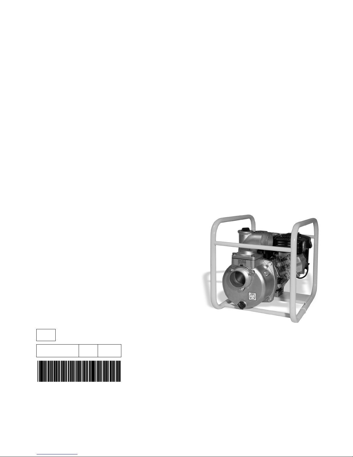
Operator’s Manual
Pump
PG 3A
EN
5000184874 08 0511
5000184874
Page 2

Copyright
notice
© Copyright 2011 by Wacker Neuson Production Americas LLC
All rights, including copying and distribution rights, are reserved.
This publication may be photocopied by the original purchaser of the machine. Any
other type of reproduction is prohibited without express written permission from
Wacker Neuson Production Americas LLC.
Any type of reproduction or distribution not authorized by Wacker Neuson Production
Americas LLC represents an infringement of valid copyrights. Violators will be
prosecuted.
Trademarks
Manufacturer
All trademarks referenced in this manual are the property of their respective owners.
Wacker Neuson Production Americas LLC
N92W15000 Anthony Avenue
Menomonee Falls, WI 53051 U.S.A.
Tel: (262) 255-0500 · Fax: (262) 255-0550 · Tel: (800) 770-0957
www.wackerneuson.com
Original
instructions
This Operator’s Manual presents the original instructions. The original language of this
Operator’s Manual is American English.
Page 3
PG 3A Foreword
Foreword
SAVE THESE INSTRUCTIONS—This manual contains important instructions for
the machine models below. These instructions have been written expressly by
Wacker Neuson Production Americas LLC and must be followed during installation,
operation, and maintenance of the machines.
Machine Item Number
PG 3A 0007659
PG 3A I 0009055
Machine
documentation
Expectations
for
information in
this manual
From this point forward in this documentation, Wacker Neuson Production
Americas LLC will be referred to as Wacker Neuson.
Keep a copy of the Operator’s Manual with the machine at all times.
Use the separate Parts Book supplied with the machine to order replacement
parts.
Refer to the separate Repair Manual for detailed instructions on servicing and
repairing the machine.
If you are missing any of these documents, please contact Wacker Neuson to
order a replacement or visit www.wackerneuson.com.
When ordering parts or requesting service information, be prepared to provide
the machine model number, item number, revision number, and serial number.
This manual provides information and procedures to safely operate and main-
tain the above Wacker Neuson model(s). For your own safety and to reduce the
risk of injury, carefully read, understand, and observe all instructions described
in this manual.
Wacker Neuson expressly reserves the right to make technical modifications,
even without notice, which improve the performance or safety standards of its
machines.
The information contained in this manual is based on machines manufactured
up until the time of publication. Wacker Neuson reserves the right to change
any portion of this information without notice.
CALIFORNIA
Proposition
65 Warning
Laws
pertaining to
spark
arresters
Engine exhaust, some of its constituents, and certain vehicle components, contain
or emit chemicals known to the State of California to cause cancer and birth
defects or other reproductive harm.
NOTICE: State Health Safety Codes and Public Resources Codes specify that in
certain locations spark arresters be used on internal combustion engines that use
hydrocarbon fuels. A spark arrester is a device designed to prevent accidental discharge of sparks or flames from the engine exhaust. Spark arresters are qualified
and rated by the United States Forest Service for this purpose. In order to comply
with local laws regarding spark arresters, consult the engine distributor or the local
Health and Safety Administrator.
wc_tx001328gb.fm 3
Page 4

Foreword PG 3A
Manufacturer’s
approval
This manual contains references to approved parts, attachments, and modifications. The following definitions apply:
Approved parts or attachments are those either manufactured or provided by
Wacker Neuson.
Approved modifications are those performed by an authorized Wacker Neu-
son service center according to written instructions published by Wacker Neuson.
Unapproved parts, attachments, and modifications are those that do not
meet the approved criteria.
Unapproved parts, attachments, or modifications may have the following consequences:
Serious injury hazards to the operator and persons in the work area
Permanent damage to the machine which will not be covered under warranty
Contact your Wacker Neuson dealer immediately if you have questions about
approved or unapproved parts, attachments, or modifications.
4 wc_tx001328gb.fm
Page 5
EC Declaration of Conformity
Manufacturer
Wacker Neuson Production Americas LLC, N92W15000 Anthony Avenue,
Menomonee Falls, Wisconsin USA
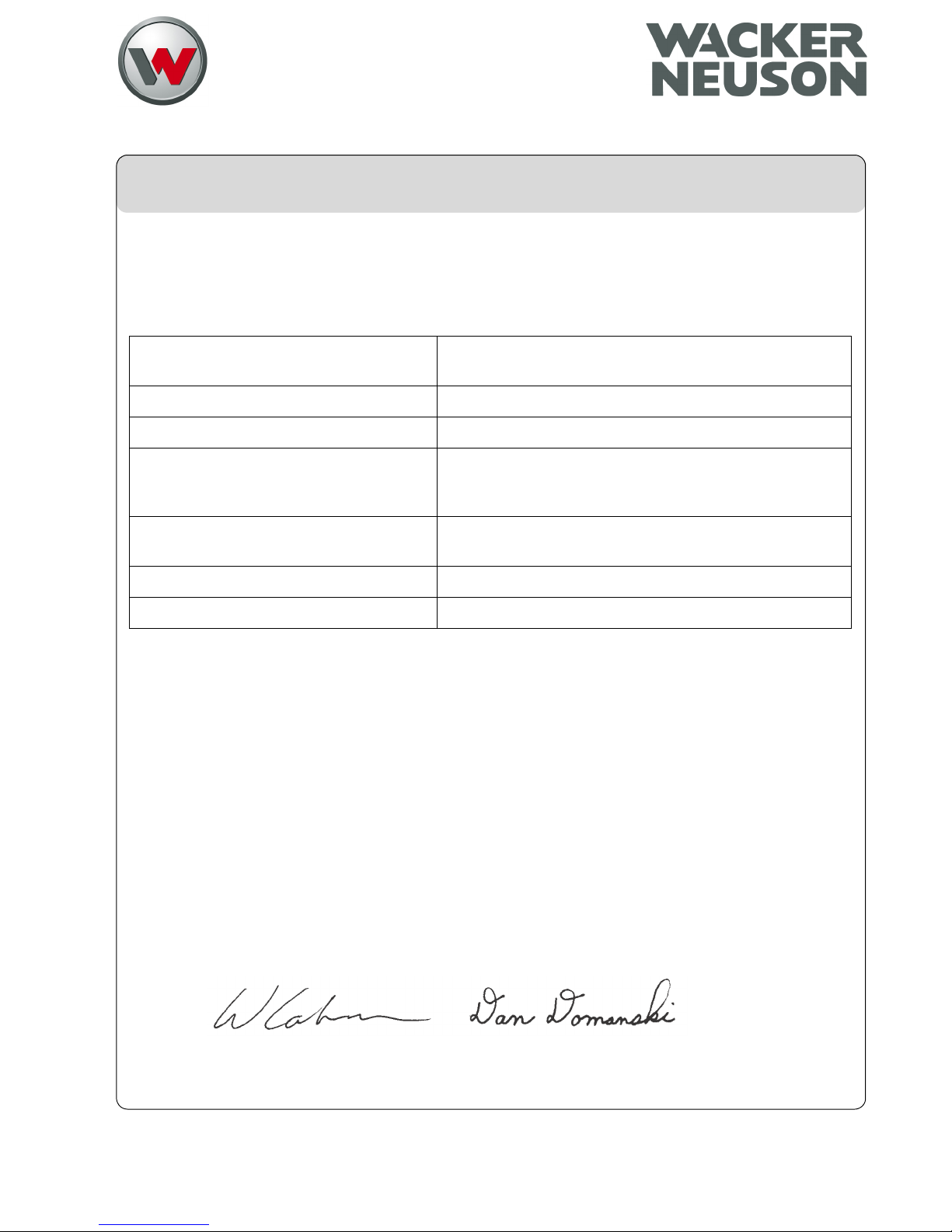
Product
Product
Product category
Product function
Item number
Net installed power
Measured sound power level
Guaranteed sound power level
PG 3A
Water Pump Units
To pump fluid
0009055
3.6 kW
105 dB(A)
105 dB(A)
Conformity Assessment Procedure
According to ANNEX V
Guidelines and Standards
We hereby declare that this product meets and complies with the relevant regulations and
requirements of the following guidelines and standards:
2006/42/EC, 2000/14/EC, 2002/88/EC, 89/336/EEC, 98/37/EEC
Authorized Person for Technical Documents
Axel Häret, Wacker Neuson SE, Preußenstraße 41, 80809 München
Menomonee Falls, WI, USA, 17.5.11
William Lahner
Vice President of Engineering
2011-CE-PG3_PG3A_en.f m
Dan Domanski
Manager, Product Engineering
Original Declaration of Conformity
Page 6

Page 7

Table of ContentsPG 3A
Foreword 3
EC Declaration of Conformity 5
1 Safety Information 9
1.1 Signal Words Used in this Manual ....................................................... 9
1.2 Machine Description and Intended Use ............................................. 10
1.3 Safety Guidelines for Operating the Machine ..................................... 11
1.4 Operator Safety while Using Internal Combustion Engines ............... 13
1.5 Service Safety .................................................................................... 14
2 Labels 16
2.1 Label Locations .................................................................................. 16
2.2 Label Meanings .................................................................................. 17
3 Lifting and Transporting 19
4 Operation 20
4.1 Preparing the Machine for First Use ................................................... 20
4.2 Recommended Fuel ........................................................................... 21
4.3 Before Starting ................................................................................... 22
4.4 Starting ............................................................................................... 23
4.5 Stopping ............................................................................................. 23
4.6 Operation ............................................................................................ 24
4.7 Hoses and Clamps ............................................................................. 24
4.8 Emergency Shutdown Procedure ....................................................... 25
wc_bo5000184874_08TOC.fm 7
Page 8

Table of Contents PG 3A
5 Maintenance 26
5.1 Maintaining the Emission Control System ...........................................26
5.2 Periodic Maintenance Schedule ..........................................................26
5.3 Cleaning the Pump ..............................................................................27
5.4 Adjusting the Impeller Clearance ........................................................28
5.5 Replacing the Mechanical Seal ...........................................................29
5.6 Spark Plug ...........................................................................................30
5.7 Servicing the Air Cleaner .....................................................................31
5.8 Engine Oil ............................................................................................32
5.9 Cleaning the Sediment Cup ................................................................33
5.10 Carburetor Adjustment ........................................................................34
5.11 Adjusting the Idle Speed .....................................................................34
5.12 Long-Term Storage .............................................................................35
6 Troubleshooting 36
7 Technical Data 37
7.1 Engine .................................................................................................37
7.2 Machine ...............................................................................................38
7.3 Sound Measurements .........................................................................38
7.4 Dimensions ..........................................................................................38
8 Emission Control Systems Information and Warranty 39
8.1 Emission Control Systems Warranty Statement .................................39
9 AEM Safety Manual 41
8 wc_bo5000184874_08TOC.fm
Page 9
PG 2A / 3A Safety Information
1 Safety Information
1.1 Signal Words Used in this Manual
This manual contains DANGER, WARNING, CAUTION, NOTICE, and
NOTE signal words which must be followed to reduce the possibility
of personal injury, damage to the equipment, or improper service.
This is the safety alert symbol. It is used to alert you to potential personal hazards.
f Obey all safety messages that follow this symbol.
DANGER
DANGER indicates a hazardous situation which, if not avoided, will result in death
or serious injury.
f To avoid death or serious injury from this type of hazard, obey all safety mes-
sages that follow this signal word.
WARNING
WARNING indicates a hazardous situation which, if not avoided, could result in
death or serious injury.
f To avoid possible death or serious injury from this type of hazard, obey all safety
messages that follow this signal word.
CAUTION
CAUTION indicates a hazardous situation which, if not avoided, could result in
minor or moderate injury.
f To avoid possible minor or moderate injury from this type of hazard, obey all
safety messages that follow this signal word.
NOTICE: Used without the safety alert symbol, NOTICE indicates a
situation which, if not avoided, could result in property damage.
Note: A Note contains additional information important to a procedure.
wc_si000069gb.fm 9
Page 10

Safety Information PG 2A / 3A
1.2 Machine Description and Intended Use
This machine is a centrifugal dewatering pump. The Wacker Neuson
Dewatering Pump consists of a tubular steel frame surrounding a
gasoline engine, a fuel tank, and an impeller pump with ports for water
suction and discharge. The engine rotates the impeller during
operation. Waste water is drawn into the pump through the suction
port and expelled through the discharge port. The operator connects
hoses to the pump and routes them so that water and solids are
drained from the work area and discharged into an appropriate
location.
This machine is intended to be used for general de-watering
applications. This machine is intended for the pumping of clear water,
or water containing solids up to the size stated within the product
specifications, and up to the flow, head and suction lift limits also
stated within the product specifications.
This machine has been designed and built strictly for the intended use
described above. Using the machine for any other purpose could
permanently damage the machine or seriously injure the operator or
other persons in the area. Machine damage caused by misuse is not
covered under warranty.
The following are some examples of misuse:
• Pumping flammable, explosive, or corrosive fluids
• Pumping hot or volatile fluids that result in pump cavitation
• Operating the pump outside of product specifications due to
incorrect diameter hoses, incorrect length hoses, other inlet or
outlet restrictions, or excessive suction lift or head
• Using the machine as a ladder, support, or work surface
• Using the machine to carry or transport passengers or equipment
• Operating the machine outside of factory specifications
• Operating the machine in a manner inconsistent with all warnings
found on the machine and in the Operator’s Manual.
This machine has been designed and built in accordance with the
latest global safety standards. It has been carefully engineered to
eliminate hazards as far as practicable and to increase operator
safety through protective guards and labeling. However, some risks
may remain even after protective measures have been taken. They
are called residual risks. On this machine, they may include exposure
to:
• Heat, noise, exhaust, and carbon monoxide from the engine
• Fire hazards from improper refueling techniques
10 wc_si000069gb.fm
Page 11
PG 2A / 3A Safety Information
• Fuel and its fumes
• Personal injury from improper lifting techniques
• Projectile hazard from discharge
• Crushing hazards from a tipping or falling pump
To protect yourself and others, make sure you thoroughly read and
understand the safety information presented in this manual before
operating the machine.
1.3 Safety Guidelines for Operating the Machine
Familiarity and proper training are required for the safe operation of the
machine. Machines operated improperly or by untrained personnel
can be hazardous. Read the operating instructions contained in this
WARNING
Operator qualifications
manual and the engine manual, and familiarize yourself with the
location and proper use of all controls. Inexperienced operators should
receive instruction from someone familiar with the machine before
being allowed to operate it.
Only trained personnel are permitted to start, operate, and shut down
the machine. They also must meet the following qualifications:
• have received instruction on how to properly use the machine
• are familiar with required safety devices
The machine must not be accessed or operated by:
•children
• people impaired by alcohol or drugs
Personal Protective Equipment (PPE)
Wear the following Personal Protective Equipment (PPE) while
operating this machine:
• Close-fitting work clothes that do not hinder movement
• Safety glasses with side shields
• Hearing protection
• Safety-toed footwear
1.3.1 Do not allow anyone to operate this equipment without proper training.
People operating this equipment must be familiar with the risks and
hazards associated with it.
1.3.2 Do not touch the engine or muffler while the engine is on or
immediately after it has been turned off. These areas get hot and may
cause burns.
1.3.3 Do not use accessories or attachments that are not recommended by
Wacker Neuson. Damage to equipment and injury to the user may
result.
wc_si000069gb.fm 11
Page 12

Safety Information PG 2A / 3A
1.3.4 Do not pump volatile, flammable, or low flash point fluids. These fluids
could ignite or explode.
1.3.5 Do not pump corrosive chemicals or water containing toxic
substances. These fluids could create serious health and
environmental hazards. Contact local authorities for assistance.
1.3.6 Do not open the priming plug when the pump is hot. Do not loosen or
remove inlet or discharge hose fittings when the pump is hot. Hot water
inside could be pressurized much like the radiator on an automobile.
Allow the pump to cool to the touch before loosening the plug and
before loosening or removing the inlet or discharge hose fittings.
1.3.7 Do not open pump housing cover while pump is operating, or start
pump with the cover off. The rotating impeller inside the pump can cut
or sever objects caught in it.
1.3.8 Do not block or restrict flow from inlet line or discharge line. Remove
kinks from discharge line before starting pump. Operation with a
blocked inlet line or discharge line can cause water inside pump to
overheat.
1.3.9 Read, understand, and follow procedures in the Operator’s Manual
before attempting to operate the machine.
1.3.10 Be sure operator is familiar with proper safety precautions and
operation techniques before using machine.
1.3.11 Be sure the machine is on a firm, level surface and will not tip, roll,
slide, or fall while operating.
1.3.12 Close fuel valve on engines equipped with one when machine is not
being operated.
1.3.13 Store the machine properly when it is not being used. The machine
should be stored in a clean, dry location out of the reach of children.
12 wc_si000069gb.fm
Page 13
PG 2A / 3A Safety Information
1.4 Operator Safety while Using Internal Combustion Engines
WARNING
Internal combustion engines present special hazards during operation and fueling.
Failure to follow the warnings and safety standards could result in severe injury or
death.
f Read and follow the warning instructions in the engine owner’s manual and the
safety guidelines below.
DANGER
Asphyxiation hazard. Using a pump indoors CAN KILL YOU IN MINUTES. Pump
exhaust contains carbon monoxide. This is a poison you cannot see or smell.
f NEVER use this pump inside a home or garage, EVEN IF doors and windows
are open. Only use OUTSIDE and far away from windows, doors, and vents.
f NEVER use a pump inside an enclosed area, such as a tunnel or a trench,
unless adequate ventilation is provided through such items as exhaust fans or
hoses.
Operating safety
When operating the pump:
• Keep the area around exhaust pipe free of flammable materials.
• Check the fuel lines and the fuel tank for leaks and cracks before
starting the engine.
When operating the pump:
• Do not smoke while operating the machine.
• Do not run the machine if fuel leaks are present or the fuel lines
are loose.
• Do not run the engine near sparks or open flames.
• Do not touch the engine or muffler while the engine is running or
immediately after it has been turned off.
• Do not operate a machine when its fuel cap is loose or missing.
• Do not start the engine if fuel has spilled or a fuel odor is present.
Move the machine away from the spill and wipe the machine dry
before starting.
Refueling safety
When refueling the engine:
• Clean up any spilled fuel immediately.
• Refill the fuel tank in a well-ventilated area.
• Replace the fuel tank cap after refueling.
wc_si000069gb.fm 13
Page 14
Safety Information PG 2A / 3A
When refueling the engine:
• Do not smoke.
• Do not refuel a hot or running engine.
• Do not refuel the engine near sparks or open flames.
• Do not refuel if the machine is positioned in a truck fitted with a
plastic bed liner. Static electricity can ignite the fuel or fuel vapors.
1.5 Service Safety
A poorly maintained machine can become a safety hazard! In order
for the machine to operate safely and properly over a long period of
time, periodic maintenance and occasional repairs are necessary.
WARNING
Personal Protective Equipment (PPE)
Wear the following Personal Protective Equipment (PPE) while
servicing or maintaining this machine:
• Close-fitting work clothes that do not hinder movement
• Safety glasses with side shields
• Hearing protection
• Safety-toed footwear
In addition, before servicing or maintaining the machine:
• Tie back long hair.
• Remove all jewelry (including rings).
1.5.1 Do not attempt to clean or service the machine while it is running.
Rotating parts can cause severe injury.
1.5.2 Do not crank a flooded engine with the spark plug removed on
gasoline-powered engines. Fuel trapped in the cylinder will squirt out
the spark plug opening.
1.5.3 Do not test for spark on gasoline-powered engines if the engine is
flooded or the smell of gasoline is present. A stray spark could ignite
the fumes.
1.5.4 Do not use gasoline or other types of fuels or flammable solvents to
clean parts, especially in enclosed areas. Fumes from fuels and
solvents can become explosive.
1.5.5 Keep the area around the muffler free of debris such as leaves, paper,
cartons, etc. A hot muffler could ignite the debris and start a fire.
1.5.6 Replace worn or damaged components with spare parts designed and
approved by Wacker Neuson.
1.5.7 When replacement parts are required for this machine, use only
Wacker Neuson replacement parts or those parts equivalent to the
14 wc_si000069gb.fm
Page 15

PG 2A / 3A Safety Information
original in all types of specifications, such as physical dimensions,
type, strength, and material.
1.5.8 Disconnect the spark plug on machines equipped with gasoline
engines, before servicing, to avoid accidental start-up.
wc_si000069gb.fm 15
Page 16
Labels PG 3A
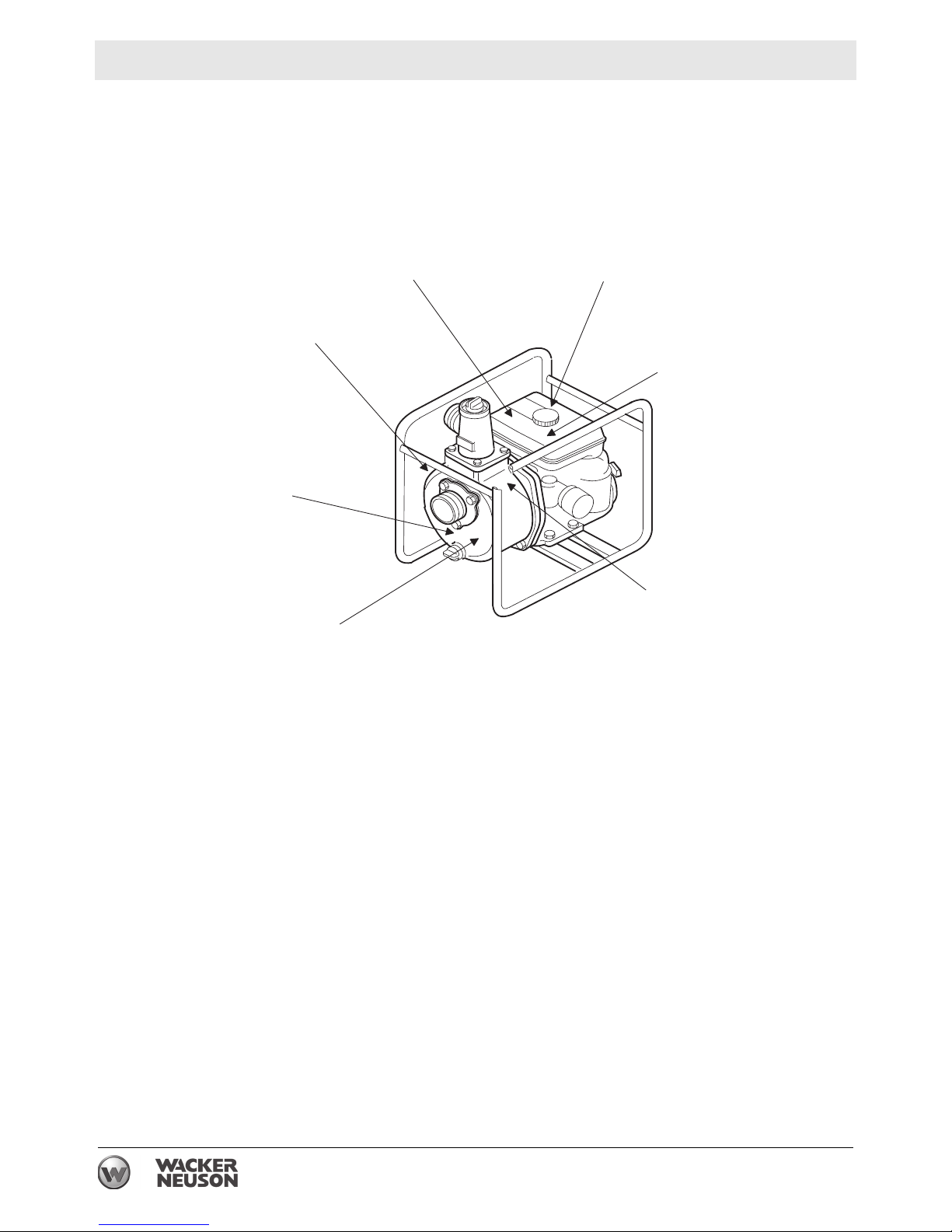
2 Labels
2.1 Label Locations
G, H
F
E
B
A
C
D
wc_gr000833
16 wc_si000519gb.fm
Page 17

PG 3A Labels
STOP
2.2 Label Meanings
A
B
DANGER!
Asphyxiation hazard.
Engines emit carbon monoxide.
Do not run the machine indoors or in an enclosed area.
NEVER use inside a home or garage, EVEN IF doors
and windows are open.
Only use OUTSIDE and far away from windows, doors,
and vents.
Read the Operator’s Manual.
No sparks, flames, or burning objects near the machine.
Stop the engine before refueling.
0178715
WARNING!
Hot surface!
C
D
CAUTION!
Read and understand the supplied Operator’s Manual
before operating this machine. Failure to do so
increases the risk of injury to yourself and others.
WARNING!
Pressurized contents. Do not open when hot!
wc_si000519gb.fm 17
Page 18

Labels PG 3A
E
F
G
H
Impeller rotation.
Guaranteed sound power level in dB(A).
A nameplate listing the model number, item number,
revision number, and serial number is attached to each
unit. Please record the information found on this nameplate so it will be available should the nameplate
become lost or damaged. When ordering parts or
requesting service information, you will always be asked
to specify the model number, item number, revision
number, and serial number of the unit.
This machine may be covered by one or more patents.
18 wc_si000519gb.fm
Page 19

PG 2A / 3A
3 Lifting and Transporting
Lifting the machine
This pump is heavy enough to cause injury if proper lifting techniques
are not used. Observe the following guidelines when lifting the pump.
• Do not attempt to lift the pump unassisted. Use appropriate lifting
equipment such as slings, chains, hooks, ramps, or jacks.
• Make sure lifting equipment is attached securely and has enough
weight-bearing capacity to lift or hold the pump safely.
• Remain aware of the location of other people nearby when lifting
the pump.
Transporting the machine
Observe the following guidelines when transporting the pump to and
from the job site.
• Drain the fuel tank before transporting the pump.
• Ensure that the pump is securely strapped down in the transport
vehicle to prevent it from sliding or tipping.
Lifting and Transporting
• Do not refuel the pump in or on the transport vehicle. Move the
pump to its operating location and then fill the fuel tank.
wc_tx001379gb.fm 19
Page 20

Operation PG 2A / 3A
4 Operation
4.1 Preparing the Machine for First Use
Preparing for first use
To prepare your machine for first use:
4.1.1 Make sure all loose packaging materials have been removed from the
machine.
4.1.2 Check the machine and its components for damage. If there is visible
damage, do not operate the machine! Contact your Wacker Neuson
dealer immediately for assistance.
4.1.3 Take inventory of all items included with the machine and verify that
all loose components and fasteners are accounted for.
4.1.4 Attach component parts not already attached.
4.1.5 Add fluids as needed and applicable, including fuel, engine oil, and
battery acid.
4.1.6 Move the machine to its operating location.
20 wc_tx000177gb.fm
Page 21

PG 2A / 3A Operation
4.2 Recommended Fuel
Type
This engine/equipment requires regular unleaded gasoline.
• Use only fresh (no older than three months old), clean gasoline.
• Use a fuel stabilizer per the fuel stabilizer manufacturer’s
instructions.
Use of oxygenated fuels
Some conventional gasolines are blended with alcohol. These
gasolines are collectively referred to as oxygenated fuels. If you use
an oxygenated fuel, be sure it is unleaded and meets the minimum
octane rating requirement.
Before using an oxygenated fuel, confirm the fuel's contents. Some
states / Provinces require this information to be posted on the fuel
pump.
The following are Wacker Neuson approved percentages of
oxygenates:
ETHANOL - (ethyl or grain alcohol) 10% by volume. You may use
gasoline containing up to 10% ethanol by volume (commonly referred
to as E10). Gasoline containing more than 10% ethanol (such as E15,
E20, or E85) may not be used because it could damage the engine.
If you notice any undesirable operating symptoms, try another service
station, or switch to another brand of gasoline.
Fuel system damage or performance problems resulting from the use
of an oxygenated fuel containing more than the percentages of
oxygenates mentioned above are not covered under warranty.
wc_tx000177gb.fm 21
Page 22

Operation PG 2A / 3A
4.3 Before Starting
See Graphic: wc_gr000835
4.3.1 Read safety instructions at the beginning of this Operator’s Manual.
4.3.2 Place pump as near to water as possible, on a firm, flat, level surface.
4.3.3 To prime pump, remove prime plug (a) and fill pump housing with
water. If the pump housing is not filled with water before starting, it will
not begin pumping.
Do not open priming plug, discharge plug, or loosen hose fittings if
pump is hot! Water or vapor inside pump may be under pressure.
WARNING
4.3.4 Check for leaks between pump and engine. If water is leaking, the seal
inside pump is worn or damaged. Continued operation may cause
water damage to engine.
4.3.5 Check that hoses are securely attached to pump. Suction hose (b)
must not have any air leaks. Tighten hose clamps (c) and couplings
(d). Check that discharge hose (e) is not restricted. Lay hose out as
straight as possible. Remove any twists or sharp bends from hose
which may block the flow of water.
4.3.6 Make sure suction strainer (f) is clean and securely attached to end of
hose. The strainer is designed to protect the pump by preventing large
objects from being pulled into the pump.
NOTICE: Strainer should be positioned so it will remain completely
under water. Running the pump with the strainer above water for long
periods can damage the pump.
4.3.7 Check fuel level, engine oil level, and condition of air cleaner.
=
@
?
A
>
?
B
w c _ g r 0 0 0 8 3 5
22 wc_tx000177gb.fm
Page 23

PG 2A / 3A Operation
4.4 Starting
See Graphic: wc_gr000014
4.4.1 Open fuel valve by moving lever to the right (a1).
Note: If engine is cold, move choke lever to close position (b1). If
engine is hot, set choke to open position (b2).
4.4.2 Turn engine switch to “ON” (e1).
4.4.3 Open throttle by moving it slightly to left (d1).
4.4.4 Pull starter rope (c).
Note: If the oil level in the engine is low, the engine will not start. If this
happens, add oil to engine. Some engines are equipped with an oil
alert light (f) that will come on while pulling the starter rope.
4.4.5 Open choke as engine warms (b2).
4.4.6 Open throttle fully to operate.
4.5 Stopping
See Graphic: wc_gr000014
4.5.1 Reduce engine RPM to idle by moving throttle completely to right (d2).
4.5.2 Turn engine switch to “OFF” (e2).
4.5.3 Close fuel valve by moving lever to the left (a2).
wc_tx000177gb.fm 23
Page 24

Operation PG 2A / 3A
_ g
4.6 Operation
Pump should begin pumping water within a minute depending on
length of suction hose and height of pump above water. Longer hoses
will require more time.
If pump does not prime, check for loose fittings or air leak in suction
hose. Make sure strainer in water is not blocked.
Run engine at full speed while operating pump.
4.7 Hoses and Clamps
See Graphic: wc_gr000836
Suction hoses (a) must be rigid enough not to collapse when pump is
operating.
Discharge hoses (b) are usually thin-walled collapsible hoses. Rigid
hoses similar to those used as suction hoses may also be used as
discharge hoses.
Note: Suction and discharge hoses are available from Wacker
Neuson. Contact your nearest dealer for more information.
Two clamps (c) are recommended for connection of suction hoses to
inlet coupling.
Note: This connection is important. Even a small air leak on the suction
side of pump will prevent the pump from priming.
For other hose connections, one T-bolt or worm-gear-type clamp is
usually sufficient to hold hoses in place. In some cases, slight
variances in hose diameters may make it necessary to add more
clamps in order to maintain tight connections.
?
=
>
w c
r 0 0 0 8 3 6
24 wc_tx000177gb.fm
Page 25

PG 2A / 3A Operation
4.8 Emergency Shutdown Procedure
If a breakdown/accident occurs while the machine is operating, follow
the procedure below.
4.8.1 Stop the engine.
4.8.2 Turn off the fuel supply.
4.8.3 Remove any obstructions.
4.8.4 Unkink the hoses.
4.8.5 Allow the machine to cool.
4.8.6 Contact the rental yard or machine owner.
wc_tx000177gb.fm 25
Page 26

Maintenance PG 2A / 3A
5 Maintenance
5.1 Maintaining the Emission Control System
Normal maintenance, replacement or repair of emission control
devices and systems may be performed by any repair establishment
or individual; however, warranty repairs must be performed by a
dealer/service center authorized by the engine manufacturer. See the
supplied engine owner’s manual for the applicable emission warranty
information.
5.2 Periodic Maintenance Schedule
The table below lists basic machine maintenance. Tasks designated
with check marks may be performed by the operator. Tasks
designated with square bullet points require special training and
equipment.
Check fuel level.
Check engine oil level.
Inspect air cleaner element.
Replace as needed.
Check external hardware.
Inspect hoses and housing for leaks.
Clean air cleaner element.
Change engine oil.
Clean cooling system.
Check and clean spark plug.
Clean sediment cup.
Daily
before
starting
3
3
3
3
3
After
first
20 hrs.
Every
50
hrs.
Every
100
hrs.
Every
300
hrs.
Check and adjust valve clearance.
Check and adjust impeller clearance.
26 wc_tx000178gb.fm
Page 27

PG 2A / 3A Maintenance
5.3 Cleaning the Pump
See Graphic: wc_gr000837
After pumping water containing a large amount of dirt or debris, clean
out inside of pump housing.
5.3.1 Remove drain plug (b) from pump housing and drain any water left in
pump.
5.3.2 Loosen the four knobs holding the pump cover (a) and remove cover.
5.3.3 Clean out dirt and debris. Inspect impeller and volute insert for wear.
The impeller may develop sharp edges. Use care when cleaning
around impeller to avoid getting cut.
WARNING
w c _ g r 0 0 0 8 3 7
=
>
wc_tx000178gb.fm 27
Page 28

Maintenance PG 2A / 3A
5.4 Adjusting the Impeller Clearance
See Graphic: wc_gr000838
If it is necessary to replace impeller or volute, be sure clearance
between impeller and volute is adjusted correctly. The impeller (a)
should be as close to the volute (b) as possible without rubbing against
it. Clearance is adjusted by adding or removing shims (c) from behind
impeller. To adjust the clearance do the following:
5.4.1 Remove pump housing but do not remove impeller.
5.4.2 Measure the distance (d) of volute.
5.4.3 Measure the distance (e) of impeller.
5.4.4 Subtract the distance (e) from (d).
(d) - (e) = (f) clearance.
5.4.5 The clearance between the volute and the impeller should be 0.3 mm
(0.012 in.) to 0.7 mm (0.028 in.). Adjust the distance by removing the
impeller and adding shims as needed.
Each shim measures 0.3 mm (0.012 in.).
As the impeller wears down, additional shims may be required to
maintain the clearance between the impeller and the volute. Check the
clearance whenever the mechanical seal (g), impeller, volute, or rear
flange plate are replaced.
e
b
d
g
c
f
a
wc_gr000838
28 wc_tx000178gb.fm
Page 29

PG 2A / 3A Maintenance
5.5 Replacing the Mechanical Seal
See Graphic: wc_gr000839
To service the mechanical seal do the following:
5.5.1 Remove the impeller (a) from the engine shaft by turning it
countercockwise.
Note: If the impeller is hard to remove, tap it with a plastic mallet. Do
not lose any adjusting shims (b).
5.5.2 Remove mechanical seal spring (c) and carbon face (d) from
crankshaft.
5.5.3 Remove mechanical seal ceramic face (e) and L-ring (f).
5.5.4 Clean engine shaft, remove any rust. Also clean contact surface of
ceramic and carbon faces with a clean cloth. Do not lubricate seal
faces.
5.5.5 Place ceramic face in L-ring and install in pump flange. Carefully place
carbon face and seal spring on engine shaft.
5.5.6 Mount impeller to engine shaft. Turn impeller shaft clockwise to
tighten. See Section Adjusting Impeller Clearance.
wc_tx000178gb.fm 29
Page 30

Maintenance PG 2A / 3A
5.6 Spark Plug
Clean or replace spark plug as needed to ensure proper operation.
Refer to the engine owner’s manual.
Recommended Plug: (NGK) BPR 6ES
The muffler becomes very hot during operation and remains hot for a
while after stopping the engine. Do not touch the muffler while it is hot.
WARNING
5.6.1 Remove spark plug and inspect it.
5.6.2 Replace plug if the insulator is cracked or chipped.
5.6.3 Clean spark plug electrodes with a wire brush.
5.6.4 Set gap (a) to 0.7-0.8 mm (0.028–0.031 in).
5.6.5 Tighten spark plug securely.
NOTICE: A loose spark plug can become very hot and may cause
engine damage.
30 wc_tx000178gb.fm
Page 31
PG 2A / 3A Maintenance
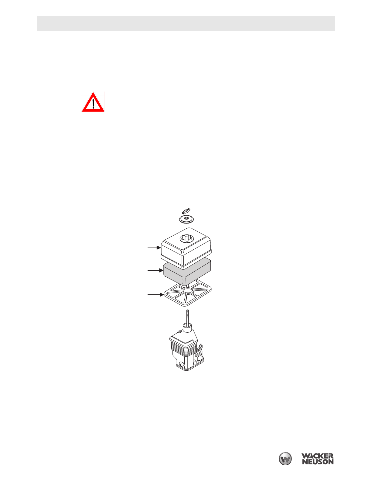
5.7 Servicing the Air Cleaner
See Graphic: wc_gr000840
Service air cleaner frequently to prevent carburetor malfunction.
NOTICE: NEVER run engine without air cleaner. Severe engine
damage will occur.
NEVER use gasoline or other types of low flash point solvents for
cleaning the air cleaner. A fire or explosion could result.
WARNING
To service:
5.7.1 Remove air cleaner cover (a). Inspect element (b) for holes or tears.
Replace element if damaged.
5.7.2 Wash element in solution of mild detergent and warm water. Rinse
thoroughly in clean water. Allow element to dry thoroughly.
Soak element in clean engine oil and squeeze out excess oil.
5.7.3 Install element, grid plate (c), and air cleaner cover.
=
>
?
w c _ g r 0 0 0 8 4 0
wc_tx000178gb.fm 31
Page 32

Maintenance PG 2A / 3A
5.8 Engine Oil
See Graphic: wc_gr000022
WARNING
Most used oil contains small amounts of materials that can cause cancer and other
health problems if inhaled, ingested, or left in contact with skin for prolonged periods of time.
f Take steps to avoid inhaling or ingesting used engine oil.
f Wash skin thoroughly after exposure to used engine oil.
5.8.1 Drain the oil while the engine is still warm.
5.8.2 Remove the oil filler plug (a) and the drain plug (b) to drain the oil.
Note: In the interests of environmental protection, place a plastic sheet
and a container under the machine to collect any liquid that drains off.
Dispose of this liquid in accordance with environmental protection
legislation.
5.8.3 Install the drain plug.
5.8.4 Fill the engine crankcase with the recommended oil up to the level of
the plug opening (c). See section Technical Data for oil quantity and
type.
5.8.5 Install the oil filler plug.
wc_gr000022
32 wc_tx000178gb.fm
Page 33

PG 2A / 3A Maintenance
5.9 Cleaning the Sediment Cup
See Graphic: wc_gr000029
5.9.1 Turn the fuel valve off.
5.9.2 Remove the sediment cup (a) and the O-ring (b).
5.9.3 Wash both thoroughly in a nonflammable solvent. Dry and reinstall
them.
5.9.4 Turn the fuel valve on and check for leaks.
wc_tx000178gb.fm 33
Page 34

Maintenance PG 2A / 3A
5.10 Carburetor Adjustment
See Graphic: wc_gr000032
5.10.1 Start the engine and allow it to warm up to operating temperature.
5.10.2 Set the pilot screw (a) two turns out. See Note.
5.10.3 With the engine idling, turn the pilot screw (a) in or out to the setting
that produces the highest rpm.
5.10.4 After the pilot screw is adjusted, turn the throttle stop screw (b) to
obtain the standard idle speed. See Technical Data.
Note: On some engines the pilot screw is fitted with a limiter cap (c)
to prevent excessive enrichment of the air-fuel mixture in order to
comply with emission regulations. The mixture is set at the factory and
no adjustment should be necessary. Do not attempt to remove the
limiter cap. The limiter cap cannot be removed without breaking the
pilot screw.
5.11 Adjusting the Idle Speed
See Graphic: wc_gr000032
To adjust idle speed:
5.11.1 Start engine and allow it to warm up to normal operating temperature.
5.11.2 Turn throttle stop screw (b) in to increase speed, out to decrease
speed.
wc_gr000032
34 wc_tx000178gb.fm
Page 35

PG 2A / 3A Maintenance
5.12 Long-Term Storage
If pump is being stored for more than 30 days:
Do not open priming plug, discharge plug, or cover when pump is hot.
WARNING
5.12.1 After pump has cooled, remove discharge plug from pump housing
and drain out any water left in the housing.
5.12.2 Remove pump cover and clean inside of pump housing. Coat inside of
pump with a light film of oil to reduce corrosion. A spray can of oil works
well for this.
5.12.3 Tape up suction and discharge ports to prevent anything from falling
into pump.
5.12.4 Change engine oil and follow procedures described in engine manual
for engine storage.
5.12.5 Cover pump and engine and store in a clean, dry area.
wc_tx000178gb.fm 35
Page 36

Troubleshooting PG 2A/3A
6 Troubleshooting
Problem / Symptom Reason / Remedy
Pump does not take in water. • Not enough priming water in housing.
• Engine speed too low. Adjust speed.
• Strainer plugged. Clean strainer.
• Suction hose damaged. Replace or repair hose.
• Air leak at suction port. Check that fittings are tight
and sealing properly.
• Pump too high above water.
• Debris collecting in pump housing. Clean pump
housing.
• Too much clearance between impeller and insert.
Pump takes in water, little or
no discharge.
Suction hose leaks at inlet. • Clamps are not sealing properly. Tighten, replace, or
Discharge hose does not stay
on coupling.
• Engine speed too low. Adjust speed.
• Suction strainer partially plugged. Clean strainer.
• Impeller worn. Adjust clearance by adding shims or
replace impeller.
• Volute insert worn or damaged. Adjust clearance or
replace insert.
add clamp.
• Hose diameter is too large.
• Hose is damaged.
• Pressure may be too high for clamps being used.
Add another clamp.
• Hose kinked or end blocked. Check hose.
Impeller does not turn; pump
is hard to start.
• Impeller jammed or blocked. Open pump cover and
clean dirt and debris from inside of pump housing.
• Impeller and insert binding. Adjust clearance by
removing shim from behind insert.
36 wc_tx001575gb.fm
Page 37

PG 3A Technical Data
7 Technical Data
7.1 Engine
Engine Power Rating
Net power rating per SAE J1349. Actual power output may vary due to
conditions of specific use.
Item Number: PG 3A
0009055 Rev. 102
and lower,
0009055 Rev. 103
PG 3A
and higher
0007659
Engine
Engine make Honda
Engine model GX160K1WKT2 GX160K1WKT4
Maximum rated power
kW (Hp)
3.6 (4.8) @ 3600 rpm
@ rated speed
Operating speed
Spark plug
Electrode gap
Air cleaner
Engine lubrication
Engine oil capacity
rpm
type
mm (in.)
type
oil grade
class
ml (oz.)
3600 ± 100
NGK BPR 6ES
0.7–0.8 (0.028–0.031)
Single element
SAE 10W30
SG or SF
600 (20)
Fuel
Fuel tank capacity
Valve clearance (cold)
wc_td000050gb.fm 37
type
L (qt)
mm (in.)
Regular unleaded gasoline
3.6 (3.8)
Inlet: 0.15 ( 0.006)
Outlet: 0.20 (0.008)
Page 38

Technical Data PG 3A
7.2 Machine
Pump
Weight
*Max. suction lift
Max. total head
Suction / discharge dia.
Maximum solid size
Max. discharge
* Based on pump operating at sea level. Maximum suction lift will be less at higher altitudes.
kg (lb)
m (ft)
m (ft)
mm (in.)
mm (in.)
L/min (gpm)
31 (69)
7.5 (25)
30 (98)
75 (3)
6.5 (0.25)
1000 (264)
7.3 Sound Measurements
The required sound specification, Paragraph 1.7.4.f of 89/392/EEC
Machinery Directive, is:
- the sound pressure level at operator’s location (LpA) = 87 dB(A)
- the sound power level (LWA) = 108 dB(A)
These sound values were determined according to ISO 3744 for the
sound power level (LWA) and ISO 6081 for the sound pressure level
(LpA) at the operator’s location.
The sound specifications were obtained with the unit operating on
pavement at nominal engine speed.
7.4 Dimensions
mm (in.)
38 wc_td000050gb.fm
Page 39

Emission Control Systems Information and Warranty
8 Emission Control Systems Information and Warranty
The Emission Control Warranty and associated information is valid only for the
U.S.A., its territories, and Canada.
8.1 Emission Control Systems Warranty Statement
See the supplied engine owner’s manual for the applicable exhaust and
evaporative emission warranty statement.
wc_tx001753gb.fm 39
Page 40

Emission Control Systems Information and Warranty
40 wc_tx001753gb.fm
Page 41

Page 42

Page 43

Page 44
Page 45

Page 46

Page 47

Page 48

Page 49

Page 50

Page 51

Page 52

Page 53

Page 54

Wacker Neuson SE, Preußenstraße 41, D-80809 München, Tel.: +49-(0)89-3 54 02-0 Fax: +49 - (0)89-3 54 02-390
Wacker Neuson Production Americas LLC, N92W15000 Anthony Ave., Menomonee Falls, WI 53051
Wacker Neuson Limited - Room 1701–03 & 1717–20, 17/F. Tower 1, Grand Century Place, 193 Prince Edward Road West, Mongkok, Kowloon, Hongkong.
Tel. : (262) 255-0500 Fax: (262) 255-0550 Tel.: (800) 770-0957
Tel: (852) 3605 5360, Fax: (852) 2758 0032
 Loading...