

Page 1
Laser Level
Nivel láser
Niveau électronique
PAL 450
OPERATOR’S MANUAL
Manual de Operación
Notice d’Emploi
www.wackerneuson.com
0171957 003
0509
0171957
Page 2

Page 3

PAL 450 Table of Contents
wc_bo0171957q4_003TOC.fm 3
Foreword EN-5
1. Safety Information EN-7
1.1 Operating Safety ............................................................................ EN-8
1.2 Service Safety ................................................................................ EN-8
1.3 Label Locations .............................................................................. EN-9
1.4 Safety and Operating Labels .......................................................... EN-9
2. Operation EN-10
2.1 Application .................................................................................... EN-10
2.2 Calibration .................................................................................... EN-10
2.3 Setup and Operation Locations .................................................... EN-10
2.4 Using the Laser ............................................................................ EN-11
2.5 Laser Detector .............................................................................. EN-12
2.6 Other Accessories ........................................................................ EN-14
3. Maintenance EN-15
3.1 Calibration overview ..................................................................... EN-15
3.2 Checking Calibration .................................................................... EN-15
3.3 Calibration Adjustment ................................................................. EN-16
3.4 Battery Pack ................................................................................. EN-17
3.5 Care and Handling ....................................................................... EN-19
4. Troubleshooting EN-19
5. Technical Data EN-20
5.1 PAL 450 Laser Level .................................................................... EN-20
5.2 Laser Detector .............................................................................. EN-21
Page 4

Page 5

Foreword
wc_tx001230gb.fm EN-5
Foreword
This manual provides information and procedures to safely operate
and maintain this Wacker Neuson model. For your own safety and
protection from injury, carefully read, understand and observe the
safety instructions described in this manual.
Keep this manual or a copy of it with the machine. If you lose this
manual or need an additional copy, please contact Wacker Neuson
Corporation. This machine is built with user safety in mind; however,
it can present hazards if improperly operated and serviced. Follow
operating instructions carefully! If you have questions about operating
or servicing this equipment, please contact Wacker Neuson
Corporation.
The information contained in this manual was based on machines in
production at the time of publication. Wacker Neuson Corporation
reserves the right to change any portion of this information without
notice.
All rights, especially copying and distribution rights, are reserved.
Copyright 2009 by Wacker Neuson Corporation.
No part of this publication may be reproduced in any form or by any
means, electronic or mechanical, including photocopying, without
express written permission from Wacker Neuson Corporation.
Any type of reproduction or distribution not authorized by Wacker
Neuson Corporation represents an infringement of valid copyrights
and will be prosecuted. We expressly reserve the right to make
technical modifications, even without due notice, which aim at
improving our machines or their safety standards.
Page 6

Foreword
wc_tx001230gb.fm EN-6
Page 7
PAL 450 Safety Information
wc_si000243gb.fm EN-7
1 Safety Information
This manual contains DANGER, WARNING, CAUTION, NOTICE, and
NOTE callouts which must be followed to reduce the possibility of
personal injury, damage to the equipment, or improper service.
This is the safety alert symbol. It is used to alert you to potential
personal injury hazards. Obey all safety messages that follow this
symbol to avoid possible injury or death.
DANGER indicates a hazardous situation which, if not avoided, will
result in death or serious injury.
WARNING indicates a hazardous situation which, if not avoided, could
result in death or serious injury.
CAUTION indicates a hazardous situation which, if not avoided, could
result in minor or moderate injury.
NOTICE: Used without the safety alert symbol, NOTICE indicates a
situation which, if not avoided, could result in property damage.
Note: Contains additional information important to a procedure.
DANGER
WARNING
CAUTION
Page 8

PAL 450 Safety Information
wc_si000243gb.fm EN-8
1.1 Operating Safety
1.1.1 Read, understand, and follow procedures in the Operator’s Manual
before attempting to operate the machine.
1.1.2 Store the machine properly when it is not being used. The machine
should be stored in a clean, dry location out of the reach of children.
1.1.3 Always operate the machine with all safety devices and guards in
place and in working order.
1.1.4
1.2 Service Safety
A poorly maintained machine can become a safety hazard! In order
for the machine to operate safely and properly over a long period of
time, periodic maintenance and occasional repairs are necessary.
1.2.1 All adjustments and repairs MUST be completed before operation. Do
not operate the machine with a known problem or deficiency! All
repairs and adjustments should be completed by a qualified
technician.
1.2.2 Do not modify the machine without the express written approval of the
manufacturer.
1.2.3 Keep the machine clean and labels legible. Replace all missing and
hard-to-read labels. Labels provide important operating instructions
and warn of dangers and hazards.
1.2.4 ALWAYS do periodic maintenance as recommended in the Operator’s
Manual.
WARNING
Page 9
PAL 450 Safety Information
wc_si000243gb.fm EN-9
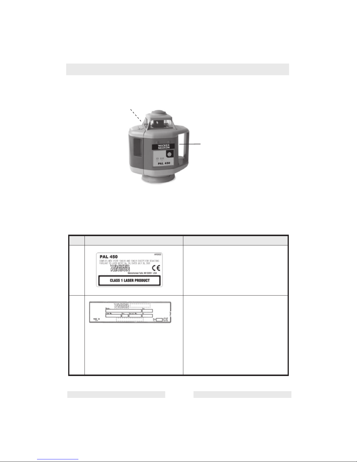
1.3 Label Locations
1.4 Safety and Operating Labels
Ref. Label Meaning
A The PAL 450 is a Class 1 laser product,
manufactured to comply with the rules of
the Code of Federal Regulations 1040.10
and 1040.11, except for deviations
pursuant to Laser Notice No. 50, dated
July 26, 2001.
B A nameplate listing the model number,
item number, revision number, and serial
number is attached to each unit. Please
record the information found on this plate
so it will be available should the
nameplate become lost or damaged.
When ordering parts or requesting
service information, you will always be
asked to specify the model number, item
number, revision number, and serial
number of the unit.
A
B
wc_gr004606
WACKER NEUSON CORPORATION
Page 10
PAL 450 Operation
wc_tx000804gb.fm EN-10
2 Operation
2.1 Application
This Wacker Neuson laser transmitter is simple to use, yet it has
several advanced features:
• Automatic self-leveling in horizontal
• High precision
• Ideal for screeding, general construction, site preparation, and
other leveling applications
2.2 Calibration
It is important to check your laser for proper calibration. The laser is a precision instrument and it is important that you keep it calibrated and in proper
condition. The accuracy of your work is completely your responsibility and you
should check your instrument before beginning each job, and especially after
the instrument has taken a sharp jolt or been dropped, or when temperature
changes greater than 50 degrees F (28 degrees C) have occurred. See “Maintenance” for calibration procedures.
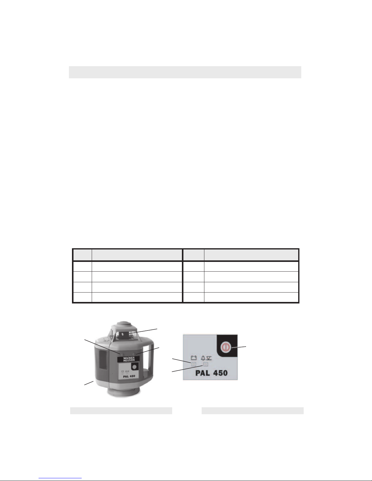
2.3 Setup and Operation Locations
Ref. Description Ref. Description
1 Rotating head 5 Level indicator
2 X-axis calibration port 6 Battery indicator
3 Y-axis calibration port 7 Battery pack
4 On / Off switch
2
3
7
1
6
5
wc_gr004579
4
Page 11

PAL 450 Operation
wc_tx000804gb.fm EN-11
2.4 Using the Laser
See Graphic: wc_gr004579
Setup:
The laser mounts to any 5/8" x 11 tripod (flathead or domed) or can
rest on any stable flat surface (floor, bricks, etc.). Position the tripod,
attach the laser, then adjust the tripod until it is rough leveled (within ±
4° self-leveling range).
Turning on the Laser:
Press the ON / OFF key (4) to power up the laser. The unit's selfchecking system will start automatically. Both LEDs (5 and 6) will flash
if anything goes wrong during the self-check procedure. The battery
LED should be green. If batteries are low, the battery LED will be red
or both LEDs will flash.
Leveling:
When the laser is turned on, the level indicator LED (5) will flash red
until the unit is level. If the laser fails to self-level within 90 seconds, the
LED will light and remain lit. Re-adjust the tripod to bring the laser into
self-leveling range. When the unit is level, the rotor head will begin
spinning at 600 rpm.
Level Alert:
If laser is disturbed, the level alert system will stop head rotation. The
laser will self-level and return to operation automatically unless it is
disturbed again while in the self-leveling range (± 4°). Always recheck
the beam height against a benchmark when releveling is required.
Power Sources:
The laser can be operated with the alkaline battery pack (4 D-size
batteries) or the optional NiCd rechargeable battery pack. If using a
NiCd battery pack, charge it completely before flrst use. The NiCd
battery pack can also be charged while working. If electricity is
available on the job site, simply plug in the charger and keep working.
Page 12

PAL 450 Operation
wc_tx000804gb.fm EN-12
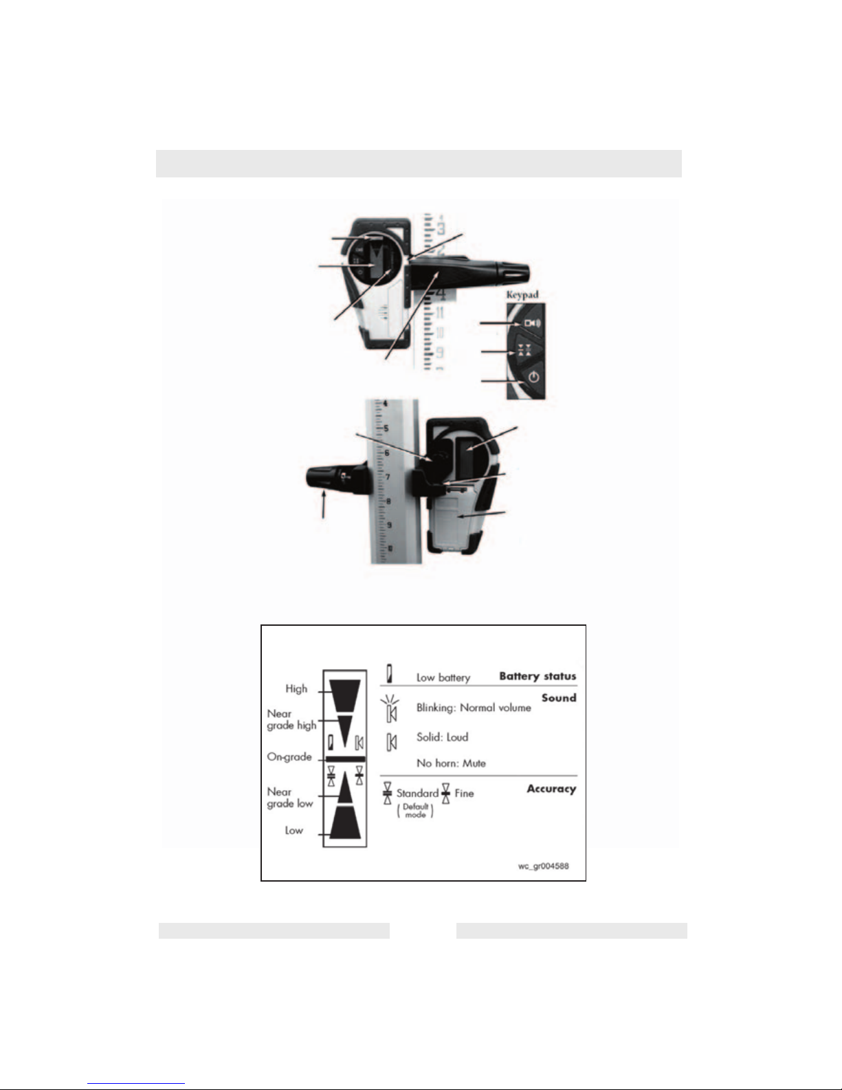
2.5 Laser Detector
Your laser transmitter is provided with a laser detector to be used with
a grade rod or handheld applications.
See graphic: wc_gr004586
Ref. Description Ref. Description
1 Level vial 8 ON / OFF
2 LCD screen (front) 9 Turn to attach clamp to detector
3 Detection window 10 Turn to tighten or remove clamp
from grade rod
4 Rod clamp 11 9V battery compartment
(Follow polarity indications inside)
5 On-grade alignment notch 12 Bubble vial to plumb rod
6 Choice of sound level 13 LCD screen (rear)
7 Choice of accuracy
Page 13
PAL 450 Operation
wc_tx000804gb.fm EN-13
wc_gr004586
1
2
3
4
5
6
7
8
9
10
13
12
11
LCD Display
Page 14

PAL 450 Operation
wc_tx000804gb.fm EN-14
See graphic: wc_gr004586 and wc_gr004588
Using the detector:
2.5.1 Press the ON / OFF key (8) to turn on the detector.
2.5.2 Press the middle key (7) to select the accuracy (deadband).
2.5.3 Press the top key (6) to select the sound level.
2.5.4 Turn the detection window (3) towards the laser beam, and move the
detector up or down according to the information given on the LCD
screen (2). There are five channels of information, or grade indicators.
2.5.5 A down arrow indicates that you must move the detector down to reach
the laser reference; and up arrow indicates that you must move it up.
When a horizontal line appears on the display, the detector is at the
same level as the laser beam.
2.5.6 Press the ON / OFF key to turn the detector off. It will automatically
sound a warning beep and shut off after 10 minutes if not used.
2.5.7 Keep the detection window clean, using a soft cloth and glass cleaner.
2.6 Other Accessories
Contact your Wacker Neuson dealer for information about available
accessories.
Page 15

Maintenance PAL 450
wc_tx000807gb.fm EN-15
3 Maintenance
3.1 Calibration overview
THIS SECTION IS VERY IMPORTANT: Here are a few simple
instructions to check your laser for calibration. The laser is a precision
instrument and it is important that you keep it calibrated and in proper
condition. The accuracy of your work is completely your responsibility
and you should check your instrument before beginning each job, and
especially after the instrument has taken a sharp jolt or been dropped,
or when temperature changes greater than 28°C (50°F) have
occurred.
Calibration should be checked regularly. For convenience, you should
establish a range for routine and quick checks. Your Wacker Neuson
dealer can assist you in setting up this range. Allow at least 15 minutes
for the laser to warm up before checking or adjusting calibration.
3.2 Checking Calibration
3.2.1 Select a level range at least 100 ft. (30 m) long. Set up the laser on a
flat surface or tripod. Approximately 100 ft. (30 m) away, erect a
vertical pole or rod.
3.2.2 Position the laser so one axis is aligned toward pole at end of the
range.
3.2.3 Turn the laser on and allow it to self-level.
3.2.4 Using a detector, mark the elevation of the beam at the pole. This is
mark “A.”
3.2.5 Rotate the laser 180° so the axis is again aligned with the pole, but in
the opposite direction. Use the detector again to mark the elevation of
the beam at the pole. This is mark “B.”
3.2.6 If marks A and B are within 1/8" (2.5 mm), calibration is correct.
3.2.7 Repeat the above procedure for the other axis. If marks are more than
1/8” (2.5 mm) apart, proceed to “Calibration Adjustment.”
Page 16
PAL 450 Maintenance
wc_tx000807gb.fm EN-16
3.3 Calibration Adjustment
See graphics: wc_gr004603 and wc_gr004604
3.3.1 Make new “A” and “B” marks as directed in “Checking Calibration.”
Make a third mark halfway between the new A and B. Call this mark
“C.” This is the correct beam center.
3.3.2 The calibration port for each axis is located on the top front of the laser.
Choose the X axis port (2) or the Y axis port (3) as necessary. Open
only one cover at a time to avoid adjusting the wrong axis.
3.3.3 Using a small screwdriver, carefully turn the exposed calibration port
adjustment screw left or right until the beam is centered at mark C.
Make adjustments in small, careful increments. After each adjustment,
check beam movement at the pole.
3.3.4 Double check the axis. Rotate the laser 180° and again check the
beam. The beam should now strike within 1/16" (1.5 mm) of mark C. If
not, repeat steps 1–3, adjusting as needed until the axis is calibrated.
3.3.5 Check and adjust the calibration of the other axis. Calibration is
complete when mark C is the same for both axes in both directions.
2
3
wc_gr004604
wc_gr004603
FRONT
X Axis
Top View
Y Axis
Page 17
Maintenance PAL 450
wc_tx000807gb.fm EN-17
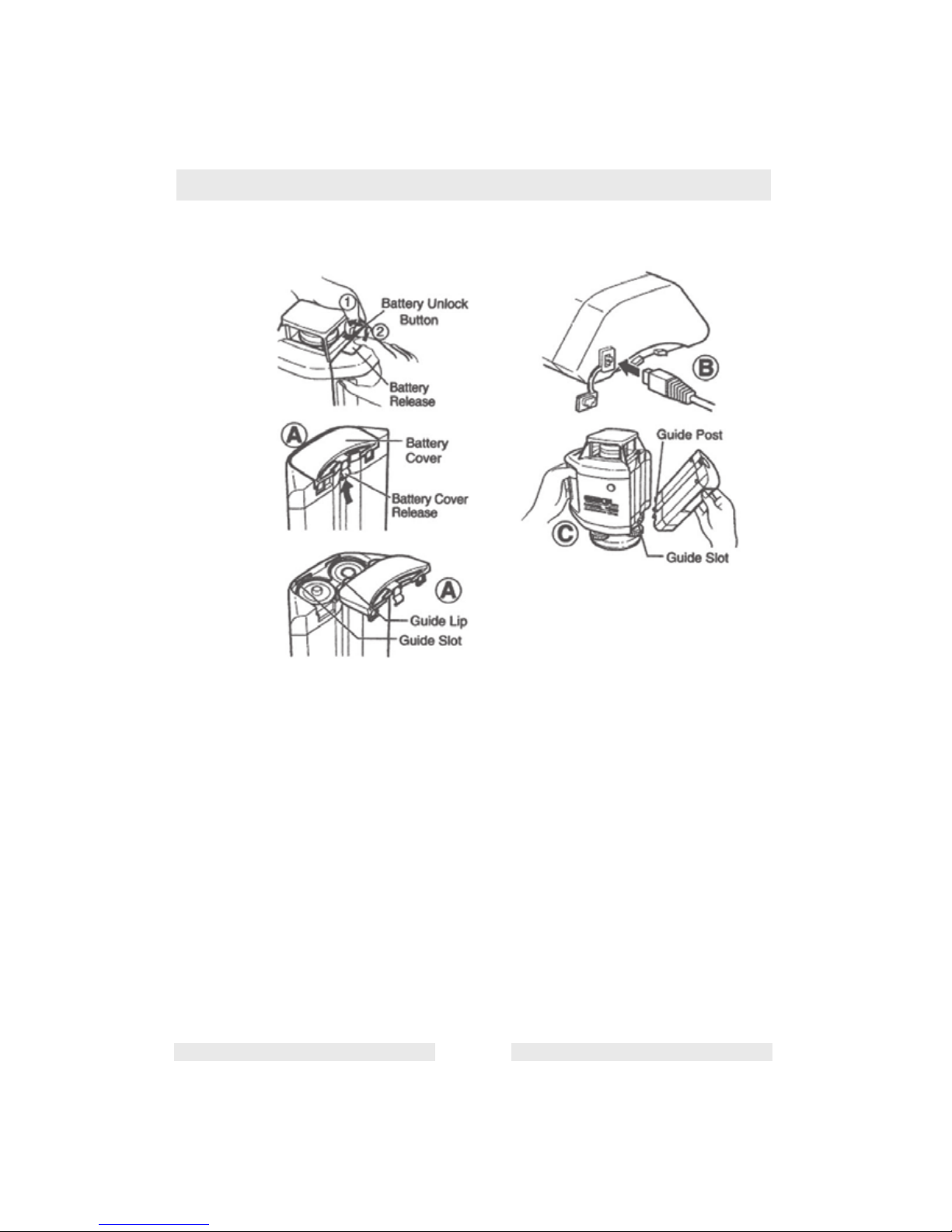
3.4 Battery Pack
See graphic: wc_gr004602
To replace the alkaline batteries, or to charge the NiCd pack, first
remove the battery pack. The NiCd pack must be charged before first
use.
Removing the Battery Pack
3.4.1 Press the battery unlock button -- see (1) in the graphic above.
3.4.2 Supporting the battery, press the battery release (2) to remove it.
A) Battery Replacement
3.4.1 Raise the battery cover release to remove the battery cover.
3.4.2 Insert 4 D batteries. The insertion direction of the batteries is indicated
on the battery pack.
3.4.3 Attach the battery cover, inserting the guide lips into the guide slots.
B) Recharging (optional NiCd pack)
3.4.1 Remove the charging connector cap on the battery pack and plug in
the charger.
3.4.2 Plug the charger into an electrical outlet. A red light on the charger
indicates that it is charging.
wc_gr004602
Page 18

PAL 450 Maintenance
wc_tx000807gb.fm EN-18
3.4.3 When the red light blinks (lights on for 6 seconds, off for 20 seconds),
the charging is finished. Charging time is about 7.5 hours. The unit can
be charged while working. For optimum life of the battery, recharge the
battery after it is fully discharged. To assure battery life, do not charge
over 20 hours.
C) Installing the Battery Pack
3.4.1 Fit the guide posts of the battery into the guide slots of the laser.
3.4.2 Attach the battery to the laser by pressing the top of the battery against
the laser until a click is heard.
Page 19

Troubleshooting PAL 450
wc_tx000807gb.fm EN-19
3.5 Care and Handling
The use of controls or adjustments or performance of procedures other
than those specified herein may result in hazardous radiation
exposure.
3.5.1 The laser is a precision instrument which must be handled with care.
Avoid shock and vibrations. Always store and transport the laser and
its accessories in the carrying case.
3.5.2 Although the laser is weather resistant, make sure to clean and dry it
with a soft cloth after each use. This will increase the battery life.
3.5.3 Do not store your laser at temperatures below -4°F (-20°C) or above
176°F (80°C) because some electronic components could be
damaged.
3.5.4 To avoid water condensation inside the instrument, do not store it
inside the case if the instrument or the case is wet.
3.5.5 To maintain the laser’s precision, check and calibrate the beam
regularly.
3.5.6 Keep the glass housing around the rotating head dry and clean. Use a
soft cloth and glass cleaner to clean it.
3.5.7 Charge the batteries regularly. However, charge them only when they
are nearly drained or completely out of power. Recharging batteries
that are still usable will shorten their capacity.
4. Troubleshooting
For laser repair, calibration, or warranty repair, please contact
EQUIPRO at 1-866-378-4776.
CAUTION
Page 20

PAL 450 Technical Data
wc_td000246gb.fm EN-20
5 Technical Data
5.1 PAL 450 Laser Level
Part No.
PAL 450
0620408
Laser Level
Operating range
m (ft)
450 (1500)
diameter
Self-leveling range ± 4° (± 7%)
Accuracy Better than ± 1/16-inch @ 100 feet
(± 4 mm / 100 m)
± 8 arc seconds
Rotation speed
rpm
600
Beam type / output Infrared diode; 785 nm; 1.0 mW,
Class 1
Power sources (1) 4 “D” size alkaline battery pack
(2) Optional NiCd rechargeable bat-
tery pack
(3) AC charger with optional NiCd
battery pack
Battery life
hours
Approximately 100 (alkaline)
40 (NiCd)
Mounting base 5/8-inch x 11 flat or domed
Environmental Water resistant, IP55
Operating temperature
C (F)
–10° to 50° (14° to 122°)
Storage temperature
C (F)
–20° to 60° (–4° to 140°)
Dimensions and weight
cm (in)
kg (lbs.)
20 x 16 x 15 (8 x 6.5 x 6)
2.3 (5)
Page 21

Technical Data PAL 450
wc_td000246gb.fm EN-21
5.2 Laser Detector
Part No.
Laser Detector
0147101
Laser Detector
Range
m (ft.)
225 (750)
Accuracy
mm (in.)
Fine: ± 1 (1/16)
Standard: ± 2.5 (1/8)
Grade indication LCD and audible tones
Battery life
hours
50
Power source 9V alkaline
Environmental Waterproof (IP 66+)
Dimensions and weight
cm (in.)
kg (lbs.)
15 x 8 x 3.5 (6 x 3.25 x 1.5)
0.2 (0.35)
Page 22

Page 23

PAL 450 Tabla de materias
wc_bo0171957es_001TOC.fm ES-1
Prefacio ES-2
1. Información sobre la seguridad ES-3
1.1 Seguridad en la operación ............................................................. ES-4
1.2 Seguridad en el mantenimiento ...................................................... ES-4
1.3 Ubicación de las calcomanías ........................................................ ES-5
1.4 Calcomanías de seguridad y operación ......................................... ES-5
2. Operación ES-6
2.1 Aplicación ....................................................................................... ES-6
2.2 Calibración ..................................................................................... ES-6
2.3 Configuración y ubicaciones de operación ..................................... ES-6
2.4 Uso del láser .................................................................................. ES-7
2.5 Detector de láser ............................................................................ ES-8
2.6 Otros accesorios .......................................................................... ES-10
3. Mantenimiento ES-11
3.1 Generalidades sobre la calibración .............................................. ES-11
3.2 Revisión de la calibración ............................................................. ES-11
3.3 Ajuste de la calibración ................................................................ ES-12
3.4 Paquete de pilas ........................................................................... ES-13
3.5 Cuidado y manipulación ............................................................... ES-15
3.6 Localización de problemas ........................................................... ES-15
4. Datos técnicos ES-17
4.1 Nivel a láser PAL 450 ................................................................... ES-17
4.2 Detector de láser .......................................................................... ES-18
Page 24

wc_tx001230es.fm ES-2
Prefacio
El presente manual proporciona información y procedimientos para
operar y mantener en forma segura este modelo de Wacker Neuson.
Para su propia seguridad y protección contra lesiones, lea, comprenda
y acate cuidadosamente las instrucciones de seguridad descritas en
este manual.
Mantenga este manual o una copia con la máquina. Si extravía este
manual o necesita una copia adicional, comuníquese con Wacker
Neuson Corporation. Esta máquina está construida teniendo en mente
la seguridad del usuario; sin embargo, puede presentar riesgos si se
opera o se le da servicio incorrectamente. ¡Siga cuidadosamente las
instrucciones de operación! Si tiene consultas acerca de la operación
o servicio de este equipo, comuníquese con Wacker Neuson
Corporation.
La información contenida en este manual se basa en las máquinas
que están en producción al momento de la publicación. Wacker
Neuson Corporation se reserva el derecho de cambiar cualquier parte
de esta información sin previo aviso.
Se reservan todos los derechos, especialmente de copia y
distribución.
Copyright 2009 de Wacker Neuson Corporation.
Ninguna parte de esta publicación se puede reproducir en modo
alguno, ni por ningún medio, ya sea electrónico o mecánico,
incluyendo fotocopia, sin la autorización expresada por escrito de
Wacker Neuson Corporation.
Todo tipo de reproducción o distribución no autorizada por Wacker
Neuson Corporation infringe los derechos de autor válidos y será
penado por la ley. La empresa se reserva expresamente el derecho de
efectuar modificaciones técnicas (incluso sin previo aviso) con el
objeto de perfeccionar nuestras máquinas o sus normas de seguridad.
Page 25

Información sobre la seguridad PAL 450
wc_si000243es.fm ES-3
1. Información sobre la seguridad
Este manual contiene notas de PELIGRO, ADVERTENCIA,
PRECAUCIÓN, AVISO y NOTA, las cuales precisan ser seguidas
para reducir la posibilidad de lesión corporal, daño a los equipos o
servicio incorrecto.
Este es el símbolo de alerta de seguridad. Se emplea para avisarle de
peligros potenciales de lesión corporal. Obedezca todos los mensajes
de seguridad a continuación de este símbolo para evitar posibles
daños corporales o la muerte.
PELIGRO indica una situación de riesgo que, si no se evita, causará
la muerte o lesión grave.
ADVERTENCIA indica una situación de riesgo que, si no se evita,
puede causar la muerte o lesión grave.
PRECAUCIÓN indica una situación de riesgo que, si no se evita,
puede causar lesión de grado menor o moderado.
AVISO: al usarse sin el símbolo de alerta de seguridad, AVISO indica
una situación de riesgo que, si no se evita, puede causar daños a
la propiedad.
Nota: Contiene información adicional importante para un
procedimiento.
PELIGRO
ADVERTENCIA
PRECAUCIÓN
Page 26

PAL 450 Información sobre la seguridad
wc_si000243es.fm ES-4
1.1 Seguridad en la operación
1.1.1 SIEMPRE lea, entienda y siga los procedimientos en el Manual de
operación, antes de intentar operar la máquina.
1.1.2 SIEMPRE almacene la máquina de manera adecuada cuando no la
utilice. La máquina deberá almacenarse en un lugar limpio y seco que
esté fuera del alcance de los niños.
1.1.3 SIEMPRE opere la máquina con todos los dispositivos de seguridad y
de protección colocados y en funcionamiento.
1.2 Seguridad en el mantenimiento
¡Las máquinas con mantenimiento deficiente pueden presentar un
riesgo para la seguridad! A fin de que la máquina funcione en forma
segura y adecuada durante un largo período, es necesario realizar un
mantenimiento periódico y reparaciones ocasionales.
1.2.1 DEBEN realizarse todos los ajustes y las reparaciones antes de la
operación. ¡NUNCA opere la máquina a sabiendas de que hay un
problema o una deficiencia! Un técnico calificado deberá realizar todas
las reparaciones y los ajustes.
1.2.2 NO modifique la máquina sin la expresa aprobación por escrito del
fabricante.
1.2.3 SIEMPRE mantenga la máquina en condiciones de limpieza y las
calcomanías legibles. Vuelva a colocar todas las calcomanías
faltantes y cambie las que sean difíciles de leer. Las calcomanías
proporcionan instrucciones de operación importantes y advierten
sobre peligros y riesgos.
1.2.4 SIEMPRE realice el Mantenimiento periódico según las
recomendaciones en el Manual de operación.
ADVERTENCIA
Page 27

Información sobre la seguridad PAL 450
wc_si000243es.fm ES-5
1.3 Ubicación de las calcomanías
1.4 Calcomanías de seguridad y operación
Ref. Calcomanía Significado
A El PAL 450 es un láser Clase 1, fabricado
para cumplir con las reglas del Código de
Reglamentaciones Federales 1040.10
y 1040.11, excepto por las variaciones
en conformidad con el aviso sobre láser
No. 50, con fecha 26 de julio de 2001.
B Cada unidad posee una placa de
identificación con el número de modelo,
el número de referencia, el nivel de
revisión y el número de serie. Favor de
anotar los datos contenidos en la placa
en caso de que la placa de identificación
se dañe o pierda. En todos los pedidos
para repuestos o cuando se solicite
información de servicio, siempre se le
pedirá que especifique el número de
modelo, el número de referencia, el
número de revisión y el número de serie
de la unidad.
A
B
wc_gr004606
WACKER NEUSON CORPORATION
Page 28

PAL 450 Operación
wc_tx000804es.fm ES-6
2. Operación
2.1 Aplicación
Este transmisor láser Wacker Neuson es muy fácil de usar, aunque
tiene diversas funciones avanzadas:
• Nivelación automática en horizontal
• Alta precisión
• Ideal para operación con reglas vibratorias, construcción general,
preparación de obras y otras aplicaciones de nivelación
2.2 Calibración
Es importante verificar la correcta calibración del láser. El láser es un
instrumento de precisión y es importante que se mantenga calibrado y en
condiciones óptimas. La precisión de su trabajo es una responsabilidad
completamente suya, por lo que debe revisar los instrumentos antes de
comenzar cada obra, y especialmente después de que el instrumento haya
sido sacudido bruscamente o se haya caído, o bien cuando se hayan
producido cambios de temperatura superiores a 50 grados F (28 grados C).
En la sección “Mantenimiento” encontrará los procedimientos de calibración.
2.3 Configuración y ubicaciones de operación
Ref. Descripción Ref. Descripción
1 Cabezal giratorio 5 Indicador de nivel
2 Puerto de calibración del eje X 6 Indicador de la pila
3 Puerto de calibración del eje Y 7 Paquete de pilas
4 Interruptor On / Off
(Encendido / Apagado)
2
3
7
1
6
5
wc_gr004579
4
Page 29

PAL 450 Operación
wc_tx000804es.fm ES-7
2.4 Uso del láser
Consulte el gráfico: wc_gr004579
Configuración:
El láser se instala en cualquier trípode de 5/8 x 11 pulg. (plano o
con cúpula) o bien puede posarse en cualquier superficie estable (piso,
ladrillos, etc.). Coloque el trípode, instale el láser, y luego ajuste el
trípode hasta que esté relativamente nivelado (en un margen de ± 4°
respecto de la autonivelación).
Encendido del láser:
Pulse la tecla ON / OFF (ENCENDIDO / APAGADO) (4) para
encender el láser. El sistema de autorrevisión de la unidad comenzará
automáticamente. Ambos diodos LED (5 y 6) destellarán si algo sale
mal durante el procedimiento de autorrevisión. El LED de la pila debe
estar verde. Si las pilas tienen poca carga, el LED correspondiente
estará en rojo o bien ambos LED destellarán.
Nivelación:
Cuando el láser esté encendido, el LED indicador de nivel (5)
destellará en rojo hasta que la unidad esté nivelada. Si el láser no se
autonivela en 90 segundos, el LED se encenderá y permanecerá así.
Vuelva a ajustar el trípode hasta que el láser quede en el margen de
autonivelación. Cuando la unidad esté nivelada, el cabezal del rotor
comenzará a girar a 600 RPM.
Alerta de nivel:
Si el láser sufre alguna alteración, el sistema de alerta de nivel detendrá
la rotación del cabezal. El láser se autonivelará y volverá a funcionar
automáticamente a menos que vuelva a sufrir una alteración en el
margen de autonivelación (± 4°). Siempre verifique la altura del haz
respecto de una referencia conocida cuando sea preciso renivelarlo.
Fuentes de alimentación:
El láser puede funcionar con el paquete de pilas alcalinas (4 pilas
tamaño D) o con el paquete opcional de pilas recargables de NiCd.
Si usará el paquete de pilas de NiCd, cárguelo completamente
antes de utilizarlo por primera vez. El paquete de pilas de NiCd
también se puede cargar cuando la máquina está funcionando. Si se
cuenta con electricidad en la obra, basta con enchufar el cargador y
continuar trabajando.
Page 30

PAL 450 Operación
wc_tx000804es.fm ES-8
2.5 Detector de láser
Su transmisor láser viene con un detector láser que se puede utilizar
con una varilla de rasante o en aplicaciones manuales.
Consulte el gráfico: wc_gr004586
Ref. Descripción Ref. Descripción
1 Nivel de burbuja de aire 8 ON / OFF (ENCENDIDO / APAGADO)
2 Pantalla LCD (delantera) 9 Gire para fijar la presilla al detector
3 Ventana de detección 10 Gire para apretar o desprender
la presilla de la varilla de rasante
4 Presilla de la varilla 11 Compartimiento de pilas de 9V
(Acate la polaridad en su interior)
5 Muesca, alineación
de graduación
12 Burbuja a varilla de plomada
6 Opción de nivel sonoro 13 Pantalla LCD (trasera)
7 Opción de precisión
Page 31

PAL 450 Operación
wc_tx000804es.fm ES-9
wc_gr004586
1
2
3
4
5
6
7
8
9
10
13
12
11
LCD Display
Page 32

PAL 450 Operación
wc_tx000804es.fm ES-10
Consulte los gráficos: wc_gr004586 y wc_gr004588
Uso del detector:
2.5.1 Pulse la tecla ON / OFF (ENCENDIDO / APAGADO) (8) para
encender el detector.
2.5.2 Pulse la tecla intermedia (7) para seleccionar la precisión (banda
muerta).
2.5.3 Pulse la tecla superior (6) para seleccionar el nivel de sonido.
2.5.4 Gire la ventana de detección (3) hacia el haz de láser, y suba o baje el
detector según la información que aparezca en la pantalla LCD (2).
Hay cinco canales de información, o indicadores de inclinación.
2.5.5 Una flecha hacia abajo indica que debe bajar el detector hasta que
alcance la referencia del láser; y la flecha hacia arriba indica que debe
subirlo. Cuando aparezca una línea horizontal en la pantalla, el
detector está al mismo nivel que el haz del láser.
2.5.6 Pulse la tecla ON / OFF (ENCENDIDO / APAGADO) para apagar el
detector. Sonará automáticamente un tono de advertencia y se apagará
al cabo de 10 minutos si es que no se usa.
2.5.7 Mantenga la ventana de detección limpia, usando un paño
humedecido con líquido limpiavidrios.
2.6 Otros accesorios
Comuníquese con su distribuidor Wacker Neuson para obtener
información sobre los accesorios disponibles.
Page 33

PAL 450 Mantenimiento
wc_tx000807es.fm ES-11
3. Mantenimiento
3.1 Generalidades sobre la calibración
ESTA SECCIÓN ES MUY IMPORTANTE: He aquí algunas sencillas
instrucciones para revisar la calibración del láser. El láser es un
instrumento de precisión y es importante que se mantenga calibrado
y en condiciones óptimas. La precisión de su trabajo es una
responsabilidad completamente suya, por lo que debe revisar los
instrumentos antes de comenzar cada obra, y especialmente después
de que el instrumento haya sido sacudido bruscamente o se haya
caído, o bien cuando se hayan producido cambios de temperatura
superiores a 50 grados F (28 grados C).
La calibración se debe revisar regularmente. Para mayor comodidad,
se debe establecer un margen para las revisiones rutinarias y rápidas.
Para ello, puede solicitar ayuda al distribuidor Wacker Neuson. Espere
al menos 15 minutos para que el láser se entibie antes de revisar o
ajustar la calibración.
3.2 Revisión de la calibración
3.2.1 Seleccione un margen de nivel de por lo menos 100 pies (30 m) de
largo. Configure el láser en una superficie plana o en un trípode.
A unos 100 pies (30 m) de distancia, disponga un poste o varilla.
3.2.2 Coloque el láser de modo que un eje quede alineado hacia el poste en
el extremo del margen.
3.2.3 Encienda el láser y deje que se autonivele.
3.2.4 Usando un detector, marque la elevación del haz en el poste. Esta es
la marca “A”.
3.2.5 Gire el láser 180° de modo que el eje quede nuevamente alineado con
el poste, pero en la dirección contraria. Use el detector nuevamente
para marcar la elevación del haz en el poste. Esta es la marca “B”.
3.2.6 Si las marcas A y B están a menos de 1/8 pulg. (2,5 mm) de distancia,
la calibración es correcta.
3.2.7 Repita el procedimiento antedicho para el otro eje. Si las marcas están
a más de 1/8 pulg. (2,5 mm) de distancia, proceda con el “Ajuste de la
calibración”.
Page 34

PAL 450 Mantenimiento
wc_tx000807es.fm ES-12
3.3 Ajuste de la calibración
Consulte los gráficos: wc_gr004603 y wc_gr004804
3.3.1 Haga nuevas marcas “A” y “B” según se indica en “Revisión de la
calibración.” Haga una tercera marca a medio camino entre las nuevas
marcas A y B. Denomínela marca “C”. Este es el centro correcto del haz.
3.3.2 El puerto de calibración para cada eje se encuentra en la parte
superior delantera del láser. Escoja el puerto del eje X (2) o el puerto
del eje Y (3) según sea necesario. Abra una sola tapa a la vez para
evitar ajustar el eje incorrecto.
3.3.3 Usando un pequeño destornillador, gire cuidadosamente el tornillo de
ajuste izquierdo o derecho expuesto del puerto de calibración hasta
que el haz quede centrado en la marca C. Haga ajustes en
incrementos pequeños y cuidadosos. Después de cada ajuste, revise
el movimiento del haz en el poste.
3.3.4 Revise dos veces el eje. Gire el láser 180° y vuelva a revisar el haz.
Este debe quedar ahora a no más de 1/16 pulg. (1,5 mm) de la marca
C. En caso contrario, repita los pasos 1–3, realizando ajustes hasta
que el eje esté calibrado.
3.3.5 Revise y ajuste la calibración del otro eje. La calibración está completa
cuando la marca C es igual en los dos ejes y en ambas direcciones.
2
3
wc_gr004604
wc_gr004603
FRONT
X Axis
Top View
Y Axis
Page 35

PAL 450 Mantenimiento
wc_tx000807es.fm ES-13
3.4 Paquete de pilas
Consulte el gráfico: wc_gr004602
Para reemplazar las pilas alcalinas, o para cargar el paquete de NiCd,
primero retire el paquete de pilas. El paquete de NiCd se debe cargar
antes de usarlo primera vez.
Retiro del paquete de pilas
3.4.1 Pulse el botón de desbloqueo de las pilas; consulte (1) en el gráfico
anterior.
3.4.2 Sujetando la pila, presione el pestillo (2) para retirarla.
A) Reemplazo de las pilas
3.4.1 Levante el pestillo de la tapa para retirarla.
3.4.2 Inserte 4 pilas tamaño D. La dirección de inserción se indica en el
paquete de las pilas.
3.4.3 Conecte la cubierta de las pilas, insertando los rebordes guía en las
ranuras respectivas.
B) Recarga (paquete opcional de NiCd)
3.4.1 Retire la tapa del conector de carga en el paquete de pilas y enchufe
el cargador
wc_gr004602
Page 36

PAL 450 Mantenimiento
wc_tx000807es.fm ES-14
3.4.2 Enchufe el cargador en un tomacorriente eléctrico. Una luz roja indica
que ya está cargando.
3.4.3 Cuando la luz roja parpadee (se enciende durante 6 segundos y luego
se apaga por 20), la carga ha finalizado. El tiempo de carga es de unas
7 horas y media. La unidad se puede cargar mientras esté
funcionando. Para una óptima vida útil de la pila, recárguela una vez
que se haya descargado por completo. Para garantizar la vida útil de
las pilas, no las cargue más de 20 horas.
C) Instalación del paquete de pilas
3.4.1 Encaje los bornes guía de la pila en las ranuras del láser.
3.4.2 Conecte la pila al láser presionando la parte superior contra el láser
hasta que se oiga un chasquido.
Page 37

PAL 450 Localización de problemas
wc_tx000807es.fm ES-15
3.5 Cuidado y manipulación
El uso de controles, ajustes o procedimientos distintos a los
especificados en este documento pueden producir una exposición
peligrosa a la radiación.
3.5.1 El láser es un instrumento de precisión que se debe manipular con
cuidado. Evite descargas y vibraciones. Siempre almacene y traslade
el láser y sus accesorios en el maletín de transporte.
3.5.2 Si bien el láser es impermeable, cerciórese de limpiarlo y secarlo con un
paño suave después de cada uso. Esto aumentará la vida útil de la pila.
3.5.3 No almacene el láser a temperaturas inferiores a los -4°F (-20°C) o
superiores a los 176°F (80°C) ya que algunos componentes
electrónicos se podrían dañar.
3.5.4 Para evitar la condensación del agua dentro del instrumento, no lo
almacene dentro de la caja si es que uno de los dos estuviera mojado.
3.5.5 Para mantener la precisión del láser, revise y calibre el haz
regularmente.
3.5.6 Mantenga seca y limpia la caja de vidrio alrededor del cabezal
giratorio. Use un paño suave y un líquido limpiavidrios para asearla.
3.5.7 Cargue las pilas con frecuencia. Sin embargo, hágalo sólo cuando
estén casi o totalmente descargadas. Si recarga pilas que aún estén
utilizables disminuirá su capacidad.
4. Localización de problemas
Para la calibración o reparación del láser, o para una reparación por
garantía, comuníquese con su distribuidor o representante de Wacker
Neuson más cercano.
PRECAUCIÓN
Page 38

PAL 450 Localización de problemas
wc_tx000807es.fm ES-16
Notas
Page 39

PAL 450 Datos técnicos
wc_td000246es.fm ES-17
5. Datos técnicos
5.1 Nivel a láser PAL 450
Parte no.
PAL 450
0620408
Nivel a láser
Margen de operación
pies (m)
1500 (450)
diámetro
Margen de autonivelación ± 4° (± 7%)
Precisión Superior a ± 1/16 pulg. a 100 pies
(± 4 mm / 100m)
± 8 segundos de arco
Velocidad de rotación
RPM
600
Tipo / potencia de salida del haz Diodo infrarrojo; 785 nm; 1,0 mW,
Clase 1
Fuentes de alimentación (1) Paquete de 4 pilas alcalinas
tamaño “D”
(2) Paquete opcional de pilas
recargables de NiCd
(3) Cargador de CA con paquete
opcional de pilas de NiCd
Duración de las pilas
horas
Aproximadamente 100 (alcalinas)
40 (NiCd)
Base de montaje 5/8 pulg. x 11, plana o con cúpula
Ambientales Impermeable, IP55
Temperatura de operación
F (C)
14° a 122° (–10° a 50°)
Temperatura de almacenamiento
F (C)
–4° a 140° (–20° a 60°)
Dimensiones y peso
pulg. (cm)
lb. (kg)
8 x 6,5 x 6 (20 x 16 x 15)
5 (2,3)
Page 40

PAL 450 Datos técnicos
wc_td000246es.fm ES-18
5.2 Detector de láser
Parte no.
Detector de láser
0147101
Detector de láser
Margen
pies (m)
750 (225)
Precisión
pulg. (mm)
Fina: ± 1 (1/16)
Estándar: ± 2,5 (1/8)
Indicación de inclinación LCD y tonos audibles
Duración de las pilas
horas
50
Fuente de energía Alcalina de 9V
Ambientales Impermeable (IP 66+)
Dimensiones y peso
pulg. (cm)
lb. (kg)
6 x 3,25 x 1,5 (15 x 8 x 3,5)
0,35 (0,2)
Page 41

PAL 450 Table des matières
wc_bo0171957fr_001TOC.fm FR-1
Préface FR-2
1. Information de sécurité FR-3
1.1 Mesures de sécurité liées au fonctionnement ................................ FR-4
1.2 Mesures de sécurité liées à l’entretien ........................................... FR-4
1.3 Emplacements des autocollants ..................................................... FR-5
1.4 Autocollants de sécurité et de fonctionnement ............................... FR-5
2. Fonctionnement FR-6
2.1 Application ...................................................................................... FR-6
2.2 Calibrage ........................................................................................ FR-6
2.3 Emplacements de configuration et de fonctionnement .................. FR-6
2.4 Utilisation du Laser ......................................................................... FR-7
2.5 Détecteur laser ............................................................................... FR-8
2.6 Autres accessoires ....................................................................... FR-10
3. Maintenance FR-11
3.1 Survol du calibrage ....................................................................... FR-11
3.2 Vérification du calibrage ............................................................... FR-11
3.3 Ajustement du calibrage ............................................................... FR-12
3.4 Bloc-batterie ................................................................................. FR-13
3.5 Entretien et manipulation .............................................................. FR-15
3.6 Dépannage ................................................................................... FR-15
4. Caractéristiques techniques FR-16
4.1 Niveau laser PAL 450 ................................................................... FR-16
4.2 Détecteur laser ............................................................................. FR-17
Page 42

Préface
FR-2
Préface
Cette notice fournit de l’information et des procédures sur l’utilisation
sécuritaire et le maintien de ce modèle de Wacker Neuson. Pour votre
propre sécurité et protection contre les risques de blessure, veuillez
lire attentivement, bien assimiler et observer les consignes de sécurité
fournies dans cette notice.
Conserver cette notice ou un exemplaire avec la machine. Si cette
notice est perdue ou si l’on a besoin d’un autre exemplaire, contacter
la société Wacker Neuson Corporation. Cette machine a été conçue
avec comme objectif primordial la sécurité de l’utilisateur; toutefois,
elle peut présenter des dangers si elle n’est pas utilisée ou entretenue
correctement. Veuillez suivre attentivement les instructions
d’utilisation ! Pour toute question sur l’utilisation ou l’entretien de cet
équipement, contacter la société Wacker Neuson Corporation.
Les informations contenues dans cette notice portent sur des
machines en production au moment de la mise sous presse. La
société Wacker Neuson Corporation se réserve le droit de modifier
toute information sans préavis.
Tous les droits, en particulier les droits de copie et de distribution, sont
réservés.
Droit d’auteur 2009 par Wacker Neuson Corporation.
Il est interdit de reproduire tout ou une partie de cette publication, sous
quelque forme ou par quelque moyen que ce soit, électronique ou
mécanique, y compris par photocopie, sans l’autorisation écrite
préalable expresse de Wacker Neuson Corporation.
Tout type de reproduction ou de distribution non autorisé par Wacker
Neuson Corporation représente une violation des droits d’auteur en
vigueur et fera l’objet de poursuites. Nous nous réservons
expressément le droit d’apporter des modifications techniques, même
sans préavis, visant à améliorer nos machines ou leurs normes de
sécurité.
Page 43

PAL 450 Information de sécurité
wc_si000243fr.fm FR-3
1. Information de sécurité
Ce manuel contient des notations de DANGER, AVERTISSEMENT,
PRÉCAUTION, ATTENTION et REMARQUE à suivre pour réduire les
risques de blessures, de dommages à l’équipement ou d’un service
inadéquat.
Ce symbole signale une Alerte sécuritaire. Il est utilisé pour vous
avertir qu’il existe un risque potentiel de blessure corporelle.
Respecter toutes les consignes de sécurité qui suivent ce symbole
pour éviter une éventuelle blessure corporelle voire mortelle.
DANGER indique une situation dangereuse immédiate qui, si elle n’est
pas évitée, risque d’entraîner des blessures corporelles graves voire
mortelles.
AVERTISSEMENT indique une situation dangereuse qui, si elle n’est
pas évitée, risque d’entraîner des blessures corporelles graves voire
mortelles.
PRÉCAUTION indique une situation dangereuse qui, si elle n’est pas
évitée, risque d’entraîner des blessures corporelles mineures ou
modérées.
ATTENTION : utilisé sans le symbole de sécurité, ATTENTION
indique une situation dangereuse qui, si elle n’est pas évitée, risque
d’entraîner des dommages matériels.
Remarque : contient des informations complémentaires importantes
pour une procédure.
DANGER
AVERTISSEMENT
PRÉCAUTION
Page 44

PAL 450 Information de sécurité
wc_si000243fr.fm FR-4
1.1 Mesures de sécurité liées au fonctionnement
1.1.1 TOUJOURS lire, comprendre et suivre les procédures dans la Notice
d’emploi avant de tenter d’utiliser l’équipement.
1.1.2 TOUJOURS ranger correctement l’équipement lorsqu’il n’est pas
utilisé. L’équipement doit être rangé dans un endroit propre et sec,
hors de portée des enfants
1.1.3 TOUJOURS faire fonctionner l’appareil avec tous les dispositifs de
sécurité et les protections en place et en bon état.
1.2 Mesures de sécurité liées à l’entretien
Une machine mal entretenue peut représenter un risque pour la
sécurité ! Pour que l’équipement fonctionne sans danger et
correctement pendant de longues périodes, il faut un entretien
périodique et des réparations occasionnelles.
1.2.1 Tous les réglages et toutes les réparations DOIVENT être complétés
avant l’opération. NE JAMAIS faire fonctionner l’appareil sachant
qu’un problème ou une défectuosité existe ! Toutes réparations et tous
les ajustements devraient être effectuées par un technicien qualifié.
1.2.2 NE PAS modifier l’appareil sans approbation écrite expresse du
fabricant.
1.2.3 TOUJOURS garder l’appareil propre et les autocollants lisibles.
Remplacer tous les autocollants manquants et difficiles à lire. Les
autocollants offrent des instructions opérationnelles importantes et
indiquent les dangers.
1.2.4 TOUJOURS effectuer la maintenance périodique tel que recommandé
dans le Manuel de l’utilisateur.
AVERTISSEMENT
Page 45

PAL 450 Information de sécurité
wc_si000243fr.fm FR-5
1.3 Emplacements des autocollants
1.4 Autocollants de sécurité et de fonctionnement
Réf. Autocollant Signification
A Le PAL 450 est un produit laser de classe
1, fabriqué de façon à satisfaire aux
normes du Code of Federal Regulations
1040.10 et 1040.11, sauf les déviations
selon le Laser Notice No. 50 daté du
26 juillet 2001.
B Une plaque signalétique mentionnant
le numéro de modèle, le numéro de
référence, le niveau de révision et le
numéro de série de l’appareil se trouve
sur chaque unité. Veuillez inscrire
l’information qui se trouve sur la plaque
signalétique pour qu’elle soit disponible
si la plaque est perdue ou endommagée.
En commandant des pièces ou en
demandant de l’information de service,
il faut toujours mentionner le numéro
de modèle, le numéro de référence,
le niveau de révision et le numéro de
série de l’unité.
A
B
wc_gr004606
WACKER NEUSON CORPORATION
Page 46

PAL 450 Fonctionnement
wc_tx000804fr.fm FR-6
2. Fonctionnement
2.1 Application
Ce transmetteur laser Wacker Neuson est simple à utiliser, mais il
possède plusieurs fonctions avancées :
• Autonivellement à l’horizontale
• Haute précision
• Idéal pour l’aplanissement, la construction générale, la préparation
de site, et les autres applications de nivellement.
2.2 Calibrage
Il est important de vérifier que le calibrage de votre laser est correct. Le laser
est un instrument de précision et il est important de le maintenir calibré et en
bonne condition. La précision de votre travail relève entièrement de votre
responsabilité et vous devriez vérifier votre instrument avant de démarrer
chaque projet, surtout à la suite d’un impact important ou d’une chute de
l’instrument, ou lorsque la température subit des écarts de plus de 28 °C. Voir
« Maintenance » pour les procédures de calibrage.
2.3 Emplacements de configuration et de fonctionnement
Réf. Description Réf. Description
1 Tête rotative 5 Indicateur de niveau
2 Port de calibrage de l’axe X 6 Indicateur de batterie
3 Port de calibrage de l’axe Y 7 Bloc-batterie
4 Commutateur On / Off
(Marche / Arrêt)
2
3
7
1
6
5
wc_gr004579
4
Page 47

PAL 450 Fonctionnement
wc_tx000804fr.fm FR-7
2.4 Utilisation du Laser
Voir le graphique : wc_gr004579
Configuration :
Le laser s’installe sur n’importe quel trépied 5/8 po x 11 (tête plate ou
de dôme) ou peut s’appuyer sur n’importe quelle surface stable
(plancher, briques, etc.). Placer le trépied, attacher le laser, puis
ajuster le trépied jusqu’à ce qu’il soit plus ou moins à niveau
(en dedans de ± 4° la plage d’autonivellement).
Allumer le laser :
Appuyer sur la touche ON / OFF (MARCHE / ARRÊT) (4) pour allumer
le laser. Le système d’auto-diagnostique de l’unité démarre
automatiquement. Les deux DELs (5 et 6) clignoteront pour avertir
d’un malfonctionnement pendant la procédure d’auto-diagnostique. La
DEL des batteries devrat être verte. Si les batteries sont faibles, la DEL
des batteries sera rouge et les deux DELs clignoteront.
Nivellement :
En allumant le laser, la DEL indicatrice de niveau (5) clignote en rouge
jusqu’à ce que l’appareil soit à niveau. Si le laser ne réussit pas à
s’autoniveler en dedans de 90 secondes, la DEL s’allumera et
demeurera allumée. Réajuster le trépied afin de ramener le laser dans
la plage d’autonivellement. Une fois l’appareil nivelé, la tête rotative
commencera à tourner à 600 tr/min.
Alerte de niveau :
Si le laser est dérangé, le système d’alerte de niveau arrêtera la
rotation de la tête. Le laser s’autonivellera et retournera à l’opération
automatique à moins qu’il ne soit dérangé de nouveau pendant qu’il
est dans la plage d’auto-nivellement (± 4°). Toujours revérifier la
hauteur du faisceau contre une référence lorsqu’une remise à niveau
est requise.
Sources d’alimentation :
Le laser peut fonctionner avec un bloc de batteries alcalines (4 batteries
grosseur D) ou un bloc optionnel de batteries NiCd rechargeables.
Charger complètement le bloc de batteries NiCd avant la première
utilisation. Le bloc de batteries NiCd peut aussi être chargé pendant
l’opération du laser. Si l’électricité est disponible sur le chantier,
simplement brancher le chargeur et continuer à travailler.
Page 48

PAL 450 Fonctionnement
wc_tx000804fr.fm FR-8
2.5 Détecteur laser
Votre transmetteur est équipé d’un détecteur de laser qui est utilisé sur
une perche de nivellement ou pour les applications à main.
Voir le graphique : wc_gr004586
Réf. Description Réf. Description
1 Fiole de niveau 8 ON / OFF (MARCHE / ARRÊT)
2 Écran LCD (devant) 9 Tourner pour attacher la pince
au détecteur
3 Fenêtre de détection 10 Tourner pour resserrer or retirer la
pince de la perche de nivellement.
4 Pince de perche 11 Compartiment de batteries 9V
(Suivre les instructions sur la
polarité à l’intérieur)
5 Coche d’alignement sur-pente 12 Fiole en bulle pour mettre la perche
d’aplomb
6 Choix de niveau de son 13 Écran LCD (arrière)
7 Choix de précision
Page 49

PAL 450 Fonctionnement
wc_tx000804fr.fm FR-9
wc_gr004586
1
2
3
4
5
6
7
8
9
10
13
12
11
LCD Display
Page 50

PAL 450 Fonctionnement
wc_tx000804fr.fm FR-10
Voir le graphique : wc_gr004586 et wc_gr004588
Utilisation du détecteur :
2.5.1 Appuyer sur la touche ON / OFF (MARCHE / ARRÊT) (8) pour allumer
le détecteur.
2.5.2 Appuyer sur la touche du milieu (7) pour sélectionner la précision
(zone morte).
2.5.3 Appuyer sur la touche supérieure (6) pour sélectionner le niveau de son.
2.5.4 Tourner la fenêtre de détection (3) dans la direction du laser, puis
déplacer le détecteur vers le haut ou le bas selon l’information fournie
sur l’écran LCD (2). Il y a cinq canaux d’information, ou indicateurs
de pente.
2.5.5 Une flèche vers le bas indique que vous devez déplacer le détecteur
vers le bas pour atteindre la référence du laser ; et la flèche vers le
haut indique que vous devez le déplacer vers le haut. Lorsqu’une ligne
horizontale apparaît sur l’écran, le détecteur est au même niveau que
le faisceau laser.
2.5.6 Appuyer sur la touche ON / OFF (MARCHE / ARRÊT) pour éteindre le
détecteur. Il émettra automatiquement un bip d’avertissement et
s’éteindra après 10 minutes d’inactivité.
2.5.7 Maintenez la propreté de la fenêtre de détection, utilisant un chiffon
doux et un nettoyeur pour vitres.
2.6 Autres accessoires
Contacter votre concessionnaire Wacker Neuson pour plus de
renseignements concernant les accessoires disponibles.
Page 51

Maintenance PAL 450
wc_tx000807fr.fm FR-11
3. Maintenance
3.1 Survol du calibrage
CETTE SECTION EST TRÈS IMPORTANTE : on y retrouve des
instructions simples pour vérifier le calibrage de votre laser. Le laser
est un instrument de précision et il est important de le maintenir calibré
et en bonne condition. La précision de votre travail relève entièrement
de votre responsabilité et vous devriez vérifier votre instrument avant
de démarrer chaque projet, surtout à la suite d’un impact important ou
d’une chute de l’instrument, ou lorsque la température subit des écarts
de plus de 28 °C.
Le calibrage devrait être vérifié régulièrement. Il est commode d’établir
un champ de mire pour rendre les vérifications routinières plus
rapides. Votre concessionnaire Wacker Neuson peut vous aider à
mettre un tel champ de mire en place. Permettre au laser de se
réchauffer pendant au-moins 15 minutes avant de procéder à la
vérification ou l’ajustement du calibrage.
3.2 Vérification du calibrage
3.2.1 Choisir un champ de mire à niveau d’au moins 30 m de long. Installer
le laser sur une surface plane ou sur un trépied. À une distance
d’environ 30 m, ériger une perche ou une tige verticale.
3.2.2 Placer le laser de façon à ce qu’un des axes soit aligné vers la perche
à l’extrémité du champ de mire.
3.2.3 Allumer le laser et permettre qu’il s’autonivelle.
3.2.4 À l’aide d’un détecteur, marquer l’élévation du faisceau sur la perche.
Celle-ci est la marque « A ».
3.2.5 Tourner le laser par 180° de façon à ce que l’axe soit de nouveau
aligné avec la perche, mais dans la direction opposée. Utiliser le
détecteur de nouveau pour marquer l’élévation du faisceau à la
perche. Celle-ci sera la marque « B ».
3.2.6 Si les marques « A » et « B » sont en dedans de 3 mm l’une de l’autre,
le calibrage est correct.
3.2.7 Répéter cette procédure pour l’autre axe. Si les marques sont
séparées par plus de 2,5 mm, procéder à « Ajustement du calibrage ».
Page 52

PAL 450 Maintenance
wc_tx000807fr.fm FR-12
3.3 Ajustement du calibrage
Voir le graphique : wc_gr004603 et wc_gr004804
3.3.1 Effectuer de nouvelles marques « A » et « B » tel que proposé dans
la consigne « Vérifier le calibrage ». Placer une troisième marque à
mi-chemin entre les nouvelles marques A et B. Appeler celle-ci « C ».
Celle-ci est le centre correct pour le faisceau.
3.3.2 Le port de calibrage pour chaque axe se situe sur le dessus en avant
du laser. Choisir le port de l’axe X (2) ou le port de l’axe Y (3) au
besoin. Ouvrir un seul couvercle à la fois afin d’éviter d’ajuster le
mauvais axe.
3.3.3 À l’aide d’un petit tournevis, tourner délicatement la vis du port
d’ajustement de calibrage vers la gauche ou la droite jusqu’à ce que le
faisceau soit centré sur la marque C. Effectuer les changements par
petits incréments. Après chaque ajustement, vérifier le déplacement
du faisceau sur la perche.
3.3.4 Contre-vérifier l’axe. Pivoter le laser par 180° et vérifier le faisceau de
nouveau. Le faisceau devrait rencontrer la marque C en-dedans de
1,5 mm. Sinon, répéter les étapes 1 à 3, ajuster au besoin jusqu’à ce
que l’axe soit calibré.
3.3.5 Vérifier et ajuster le calibrage de l’autre axe. Le calibrage est terminé
lorsque la marque C est la même pour les deux axes.
2
3
wc_gr004604
wc_gr004603
FRONT
X Axis
Top View
Y Axis
Page 53

Maintenance PAL 450
wc_tx000807fr.fm FR-13
3.4 Bloc-batterie
Voir le graphique : wc_gr004602
Pour remplacer les batteries alcalines, ou pour charger un bloc-batterie
NiCd, retirer en premier le bloc-batterie. Le bloc-batterie NiCd doit être
chargé avant la première utilisation.
Dépose du bloc-batterie
3.4.1 Appuyer sur le bouton de déverrouillage -- voir (1) dans le graphique
ci-dessous.
3.4.2 Tout en supportant la batterie, appuyer sur la relâche de batterie (2)
pour la déposer.
A) Remplacement de la batterie
3.4.1 Soulever la relâche du couvercle pour retirer le couvercle de la batterie.
3.4.2 Insérer 4 batteries D. La direction d’insertion des batteries est indiquée
sur le porte batteries.
3.4.3 Fixer le couvercle de batteries, insérant les lèvres de guidage dans les
rainure de guidage.
B) Recharger (bloc-batterie NiCd optionnel)
3.4.1 Retirer le connecteur de charge sur le bloc-batterie et brancher
le chargeur.
wc_gr004602
Page 54

PAL 450 Maintenance
wc_tx000807fr.fm FR-14
3.4.2 Brancher le chargeur dans une prise secteur. Un voyant rouge sur le
chargeur indique qu’il effectue la charge.
3.4.3 Lorsque le voyant rouge clignote (voyant allumé pendant 6 secondes,
éteint pendant 20 secondes), la charge est complétée. Le temps
requis pour la charge est environ 7,5 heures. L’unité peut être chargée
tout en étant utilisée. Pour atteindre une durée de vie optimale de la
batterie, recharger la batterie après l’avoir complètement déchargée.
Pour assurer une longue vie à la batterie, ne pas charger pendant plus
de 20 heures.
C) Installer le bloc-batterie
3.4.1 Installer la colonne de guidage dans la rainure de guidage du laser.
3.4.2 Attacher la batterie au laser en appuyant le dessus de la batterie
contre le laser jusqu’à ce que vous entendiez un clic.
Page 55

Dépannage PAL 450
wc_tx000807fr.fm FR-15
3.5 Entretien et manipulation
L’utilisation de commandes ou des ajustements, ou l’exécution de
procédures autres que celles spécifiées dans ce document pourrait
résulter en une exposition dangereuse à de la radiation.
3.5.1 Le laser est un instrument de précision qui doit être manipulé avec
soin. Éviter les chocs et les vibrations. Toujours ranger et transporter
le laser et ses accessoires dans son étui de transport.
3.5.2 Même si le laser est résistant à l’eau, assurez-vous de le nettoyer et
de le sécher avec un chiffon doux après chaque usage. Ceci
augmentera aussi la vie utile de la batterie.
3.5.3 Ne pas ranger le laser à des températures sous -20 °C ou au-dessus
de 80 °C parce certains composants électroniques pourraient être
endommagés.
3.5.4 Pour éviter la condensation d’eau à l’intérieur, ne pas ranger celui-ci
dans son étui si l’instrument ou l’étui sont mouillés.
3.5.5 Afin de maintenir la précision du laser, vérifier et calibrer le faisceau
régulièrement.
3.5.6 Maintenir le boîtier de verre autour de la tête rotative sec et propre.
Utiliser un chiffon doux et un nettoyeur de verre pour le nettoyer.
3.5.7 Charger les batteries régulièrement. Par contre, les charger uniquement
lorsqu’elles sont presque ou complètement déchargées. Recharger les
batteries qui sont encore utilisables raccourcira leur vie utile.
4. Dépannage
Pour réparer un laser, le calibrer, ou effectuer des réparations sous
garantie, veuillez contacter ÉQUIPRO à 1-866-378-4776.
PRÉCAUTION
Page 56

PAL 450 Caractéristiques techniques
wc_td000246fr.fm FR-16
5. Caractéristiques techniques
5.1 Niveau laser PAL 450
Article
PAL 450
0620408
Niveau laser
Plage opérationnelle
m
450
diamètre
Plage d’autonivellement ± 4° (± 7 %)
Précision supérieure à ± 4 mm / 100 m
± 8 secondes d’arc
Vitesse de rotation
tr/min
600
Type de faisceau / sortie Diode infrarouge ; 785 nm ; 1,0 mW,
classe 1
Sources d’alimentation (1) bloc de 4 batteries « D »
alcalines
(2) option bloc de batteries
NiCd rechargeables
(3) option Chargeur CA avec
bloc-batterie NiCd
Vie utile des batteries
heures
environ 100 (alcaline)
40 (NiCd)
Base d’installation 1,6 cm x 18 plate ou en dôme
Écologique Étanchéité, IP55
Température opérationnelle °C –10 to 50
Température de rangement °C –20 à 60
Dimensions et poids
cm
kg
20 x 16 x 15
2,3
Page 57

Caractéristiques techniques PAL 450
wc_td000246fr.fm FR-17
5.2 Détecteur laser
Article
Détecteur laser
0147101
Détecteur laser
Distance
m
225
Précision
mm
Fine : ± 1
Standard : ± 2,5
Indication de niveau LCD et tons audibles
Vie utile des batteries
heures
50
Source d’alimentation 9V alcaline
Écologique Étanchéité (IP 66+)
Dimensions et poids
cm
kg
15 x 8 x 3,5
0,2
Page 58

Wacker Neuson SE · Preußenstraße 41 · D-80809 München · Tel.: +49-(0)89-3 54 02-0 · Fax: +49 - (0)89-3 54 02-390
Wacker Neuson Corporation · P.O. Box 9007 · Menomonee Falls, WI 53052-9007 · Tel. : (262) 255-0500 · Fax: (262) 255-0550 · Tel. : (800) 770-0957
Wacker Neuson Limited - Room 1701–03 & 1717–20, 17/F. Tower 1, Grand Century Place, 193 Prince Edward Road West, Mongkok, Kowloon, Hongkong.
Tel: (852) 3605 5360, Fax: (852) 2758 0032
AM 1040-05/09
 Loading...