

Wacker Neuson BPU 2440 series, BPU 2950 series, BPU 2650R, BPU 2440A, BPU 2950R Repair Manual
...Page 1

www.wackergroup.com
Vibroplate
BPU 2440
BPU 2950
REPAIR MANUAL
0078232 004
0603 en
0078232
Page 2

Page 3

BPU 2440/2950 Repair Foreword
wc_tx000260gb.fm i
Operating / Parts Inf o r ma t i on
You must be familiar with the operation of this machine before you
attempt to trou bl es h oot or ma ke a ny re pa irs t o it. Ba sic op er atin g an d
maintenance procedures are described in the operator’s / parts
manual supplied with the machine. The operator’s / parts manual
should be kept with the machine. Use it to order replacement parts
when needed. If this manual becomes lost, please contact Wacker
Corporation to order a replacement.
Damage caused by misuse or neg lect of the unit should be brough t to
the attention of the operator, to prevent similar occurrences from
happening in the future.
This manual provides information and procedures to safe ly repair and
maintain this Wacker model. For your own safety and protection from
injury, carefully read, understand and observe the safety instructions
described in this manual. TH E INFORM ATION CONTAINED IN THIS
MANUAL WAS BASED ON MACHINES IN PRODUCTION AT THE
TIME OF PUBLICATION. WACKER CORPORATION RESERVES
THE RIGHT TO CHANGE ANY PORTION OF THIS INFORMATION
WITHOUT NOTICE.
This manual covers machines with Item Number:
5603, 5904, 6222, 6346, 6412, 6993, 7150, 7867, 7872, 7962
Page 4

Foreword BPU 2440/2950 Repair
wc_tx000260gb.fm ii
CALIFORNIA
Proposition 65 Warning:
Engine exhaust, some of its constituents, and certain vehicle
components contain or em it chemicals known to the State of California
to cause cancer and birth defects or other reproductive harm.
All rights, especially copying and distribution ri ghts, are reserved.
Copyright 2003 by Wacker Corporation.
No part of this pu blication may be rep roduced in any form or by any
means, electronic or mechanical, including photocopying, without
express written permission from Wacker Corporation.
Any type of reproduction or distribution not authorized by Wacker
Corporation represents an infringement of valid copyrights and will be
prosecuted. We expressly reserve the right to make technical
modifications, even without due notice, which aim at improving our
machines or their safety standards.
WARNING
Page 5

Typ Table of Contents
wc_br0078232_002enTOC.fm 1
1. Safety Information 3
1.1 Operating Safety .................................................................................. 4
1.2 Operator Safety while using Internal Combustion Engines .................. 5
1.3 Service Safety ...................................................................................... 5
1.4 Labels ................................................................................................... 7
2. Technical Data 9
2.1 Engine .................................................................................................. 9
2.2 Plate ..................................................................................................... 9
2.3 Lubrication .......................................................................................... 10
2.4 Dimensions ......................................................................................... 10
3. General Information 11
3.1 Application .......................................................................................... 11
3.2 Tools ................................................................................................... 11
3.3 Ordering Parts ................................. .... ............................................... 11
3.4 Reference Numbers ( ) ....................................................................... 12
3.5 Weight Block ......................................................................................12
3.6 Lifting and Transporting the Machine .................................................12
3.7 Storage ............................................................................................... 13
3.8 Theory of Operation ...........................................................................14
3.9 Directional and Speed Control ........................................................... 16
3.10 Engine Speed and Machine Performance ..........................................18
3.11 Operating on Slopes ........................................................................... 18
3.12 To Start ............................................................................................... 19
3.13 To Stop ............................................ .... ..... .......................................... 19
4. Maintenance 20
4.1 General Maintenance ......................................................................... 20
4.2 Maintenance Schedule .................................................................... 21
4.3 Air Filter .............................................................................................. 22
4.4 Spark Plug .......................................................................................... 23
4.5 Cleaning Sediment Cup ..................................................................... 24
4.6 Adjusting Idle Speed ..........................................................................25
Page 6

Table of Contents Typ
wc_br0078232_002enTOC.fm 2
4.7 Carburetor Adjustment ........................................................................25
4.8 Drive Belt .............................................................................................26
4.9 Exciter Oil ............................................................................................27
4.10 Control Circuit Oil ................................................................................27
4.11 Bleeding the Control Circuit .................................................................28
4.12 Re-installing Piston in Control Assembly .............................................29
5. Repair Procedures 30
5.1 General Repair ....................................................................................30
5.2 Checking Exciter Operation .................................................................31
5.3 Exciter Exploded View Illustration .......................................................32
5.4 Exciter Parts List .................................................................................33
5.5 Removing Exciter ................................................................................34
5.6 Installing Exciter ........................................ ..... .... .................................35
5.7 Exciter Assembly Cross Section .........................................................36
5.8 Exciter Cross Section List of Components ..........................................37
5.9 Servicing Exciter ..................................................................................38
5.10 Disassembling the Exciter ...................................................................38
5.11 Re-assembling the Exciter ..................................................................40
5.12 Servicing the Clutch ............................................................................44
5.13 Replacing the Engine ................................ ..... .....................................45
5.14 Engine Replacement—Honda .............................................................46
5.15 Engine Replacement—Robin ..............................................................47
6. Troubleshooting 48
Page 7

BPU 2440/2950 Repair Safety Information
wc_si000099gb.fm 3
1. Safety Information
This manual contains DANGER, WARNING, CAUTION, and NOTE
callouts which must be followed to reduce the po ssibility of personal
injury, damage to the equipment, or improper service.
This is the safety alert symbol. It is used to alert you to potential
personal injury hazards. Obey all safety messages that follow this
symbol to avoid pos sible injury or death.
DANGER indicates an imminently hazardous situation which, if not
avoided, will result in death or serious injury.
WARNING indicates a potentially hazardous situation which, if not
avoided, could result in death or serious injury.
CAUTION indicates a potentially hazardous situation which, if not
avoided, may result in minor or modera te injury.
CAUTION: Used without the safety alert symbol, CAUTION indicates
a potentially hazardous situation which, if not avoided, may result in
property damage.
Note:
Contains addi tional infor m ation important to a procedure.
DANGER
WARNING
CAUTION
Page 8

Safety Information BPU 2440/2950 Repair
wc_si000099gb.fm 4
1.1 Operating Safety
Familiarity and proper training are required for the safe operation of
equipment! Equipment operated improperly or by untrained personnel
can be dangerous! Read the operating instructions contained in both
this manual and the en gine manual and familiarize yourself with the
location and prope r use of all contr ols. Inexperie nced operators shou ld
receive instruction from someone familiar with the equipment before
being allowed to operate the machine.
1.1.1 ALWAYS wear protective clothing appropriate to the job site when
operating equi pment.
1.1.2 ALWAYS remain aware of moving parts and keep hands, feet, and
loose clothing away from movi ng parts of equipment.
1.1.3 ALWAYS read, understand, and follow procedures in Operator's
Manual before attempting to operate equipment.
1.1.4 ALWAYS store equipment properly when it is not being used.
Equipment should be stored in a clean, dry location out of the reach of
children.
1.1.5 ALWAYS check that all controls are functioning properly immediately
after start-up! DO NOT operate machine unless all controls operate
correctly.
1.1.6 ALWAYS operate ma chi ne w ith all safety devices and g ua rd s i n pla c e
and in working order.
1.1.7 ALWAYS remain aware of cha ng in g positi o ns and move me nt of oth er
equipment and personnel on the jobsite.
1.1.8 ALW AY S rem ain aw are of c h angi ng s urfa ce c ond it ions a nd us e ex tr a
care when operating over uneven ground, on hills, or over soft or
coarse material. The machine could shift or slide unexpe ctedly.
1.1.9 ALWAYS be sure that all other persons are at a safe distance from the
machine. Stop the machine if people step into the working area of the
machine.
1.1.10 NEVER allow improperly trained people to operate this equipment.
People operating this equipment must be familiar with the potential
risks and hazards associated with it.
1.1.11 NEVER touch the engine or muffler while the engine is on or
immediately after i t has been turned off. The se areas get hot and may
cause burns.
1.1.12 NEVER use accessories or attachm ents that are not recom mended by
Wacker. Damage to equipment and injury to the user m ay result.
1.1.13 NEVER leave machine running unattended.
1.1.14 NEVER start a defective unit in need of service or repair.
WARNING
Page 9

BPU 2440/2950 Repair Safety Information
wc_si000099gb.fm 5
1.2 Operator Safety while using Internal Combustion En gines
Internal combusti on en gines pr esent specia l haza rds du rin g opera tion
and fueling! Read and follow warning instructio ns in engine owner's
manual and safety guidelines below. Failure to follow warnings and
safety guidelines could result in severe injury or death.
1.2.1 DO NOT r un mach ine in door s or in an enclo sed area s uch as a d eep
trench unless adequate ventilation, through such items as exhaust
fans or hoses, is provided. Exhaust gas from the engine contains
poisonous carbon monoxide gas; exposure to carbon monoxide can
cause loss of consciousness and may lead to death.
1.2.2 DO NOT smoke while operating machine.
1.2.3 DO NOT smoke when refueling engine.
1.2.4 DO NOT refuel hot or running engine.
1.2.5 DO NOT refuel engine near open flame.
1.2.6 DO NOT spill fuel when refu eling engine.
1.2.7 DO NOT run engine near open flames.
1.2.8 ALWAYS refill fuel tank in well-venti lated area.
1.2.9 ALWAYS replace fuel tank cap after refueling.
1.2.10 ALWAYS check fuel lines and fuel tank for leaks and cracks before
starting engine. Do not run machine if fuel leaks are present or fuel
lines are loose.
1.2.11 ALWAYS keep area a roun d hot exhaus t pipes free of de bris to red uce
the chance of an accidental fire.
1.3 Service Safety
Poorly maintained equipment can become a safety hazard! In order
for the equipment to operate safely and prop erly over a long period of
time, periodic maintenance and occasional repairs are necessary.
1.3.1 DO NOT stand under the machine while it is being hoisted or moved.
1.3.2 DO NOT get onto the machine while it is being hoisted or moved.
1.3.3 DO NOT use the machine as a ladder . Use safe ladders and platforms
designed for this purpose.
1.3.4 DO NOT modify the equipmen t without expre ss written approva l of the
manufacturer.
1.3.5 DO NOT attempt to clean or service machine while it is running.
Rotating parts can cause severe injury.
DANGER
WARNING
Page 10

Safety Information BPU 2440/2950 Repair
wc_si000099gb.fm 6
1.3.6 DO NOT crank a flooded engine with the spark plug removed on
gasoline-powered eng ines. Fuel trapped in the cylinder will squirt o ut
the spark plug opening.
1.3.7 DO NOT test for spark on gasoline-powered engines, if engine is
flooded or the smell of gasoline is present. A stray spark could ignite
fumes.
1.3.8 DO NOT use gasoline or oth er type s of fu el s or flam ma bl e so lvents to
clean parts, especially in enclosed areas. Fumes from fuels and
solvents can become explosive.
1.3.9 ALWAYS keep area around muffler free of debris such as leaves,
paper, cartons, etc. A hot muffler could ignite them, starting a fire.
1.3.10 ALWAYS replace worn or damaged components with spare parts
designed and recommende d by Wacke r.
1.3.11 ALWAYS keep machine clean and labels legible. Replace all missing
and hard-to-read labels. Labels provide important operating
instructions and warn of dangers and hazards.
1.3.12 ALWAYS check and tighten all external fasteners at regular intervals.
1.3.13 ALWAYS switch off the power supply at the batte ry di sco nne ct befo re
adjusting or maintaining the electrical equipment.
1.3.14 ALWAYS turn engine off before performing maintenance or making
repairs.
1.3.15 ALWAYS keep hands, feet and loose clothing away fro m moving parts.
1.3.16 ALWAYS make sure slings, chains, hooks, ramps, jacks and other
types of lifting devices are attached securely and have enough weightbearing capacity to lift or hold the machine safely. Always remain
aware of the position of other people around you when lifting the
machine.
1.3.17 Before you start the machi ne, ensure that all tools have b een removed
from the machine and th at re place ment parts and adju sters are fir mly
tightened.
Page 11
BPU 2440/2950 Repair Safety Information
wc_si000099gb.fm 7
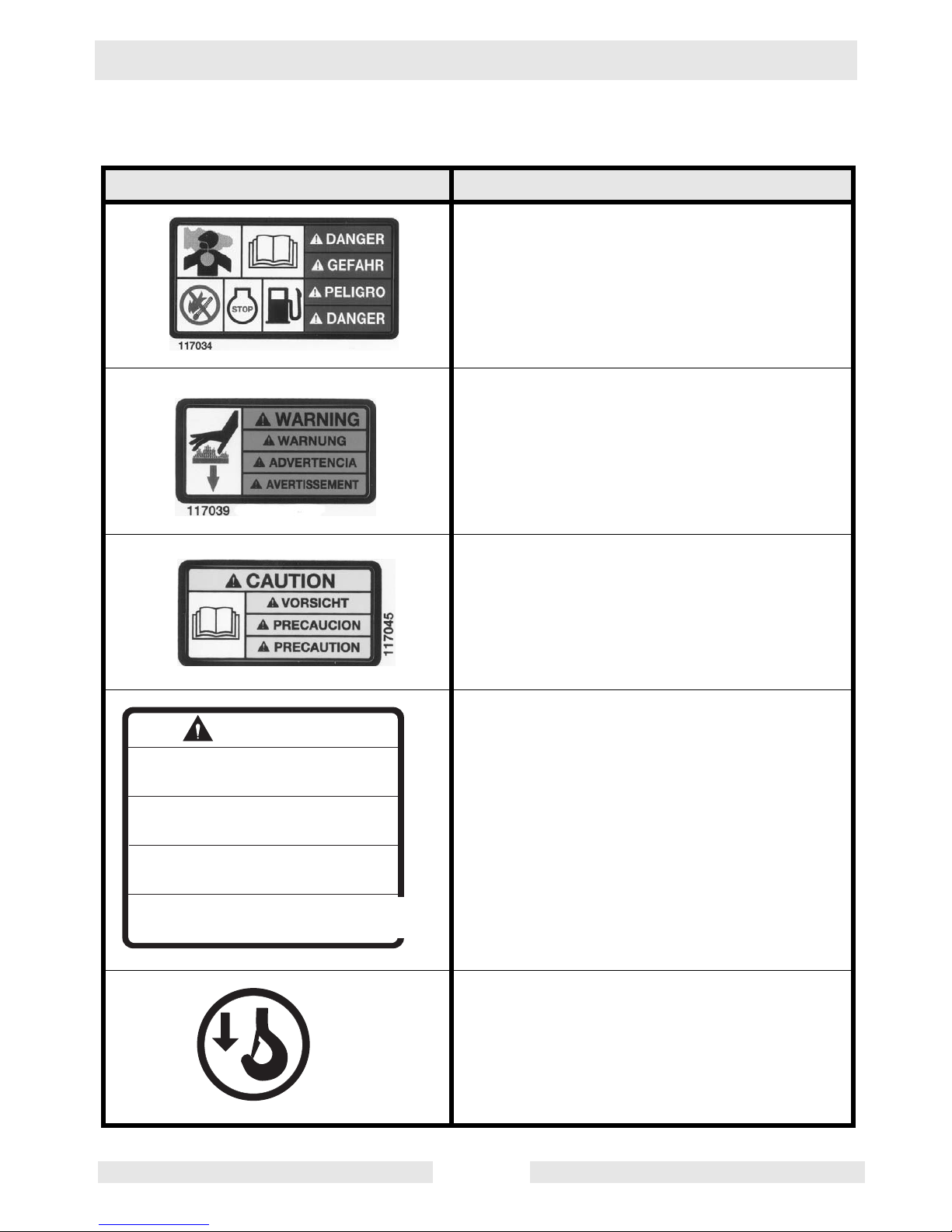
1.4 Labels
Label Meaning
DANGER!
Engines emit carbon monoxide; operate only
in well ventilated area. Read the op era tor's
manual.
No sparks, flames or burning obje cts near
machine. Shut off engine before refueling.
WARNING!
Hot surface.
CAUTION!
Read and underst and the supplied operator's
manuals before operating this machine. Failure to do so increases the risk of injury to yourself or others.
WARNING!
Do not operate without safety guards. Read
and understand instruction book.
CAUTION!
Lifting point
DO NOT OPERATE WITHOUT SAFETY
GUARDS. READ AND UNDERSTAND
INSTRUCTION BOOK.
NICHT OHNE SCHUTZVORRICHTUNG
BETREIBEN. BEDIENUNGSANWEISUNG
GENAU DURCHLESEN.
NO OPPRE SIN LOS DISPOSITIVOS
DE SEGURIDAD. LEA Y ENTIENDA
PRIMERO LAS INSTRUCCIONES.
NE PAS OPERER SANS DEFLECTEUR
PROTECTIF. LIRE ET COMPRENDRE
LES INSTRUCTIONS DE SERVICE.
WARNING
1007190
wc_gr001474
Page 12
Safety Information BPU 2440/2950 Repair
wc_si000099gb.fm 8
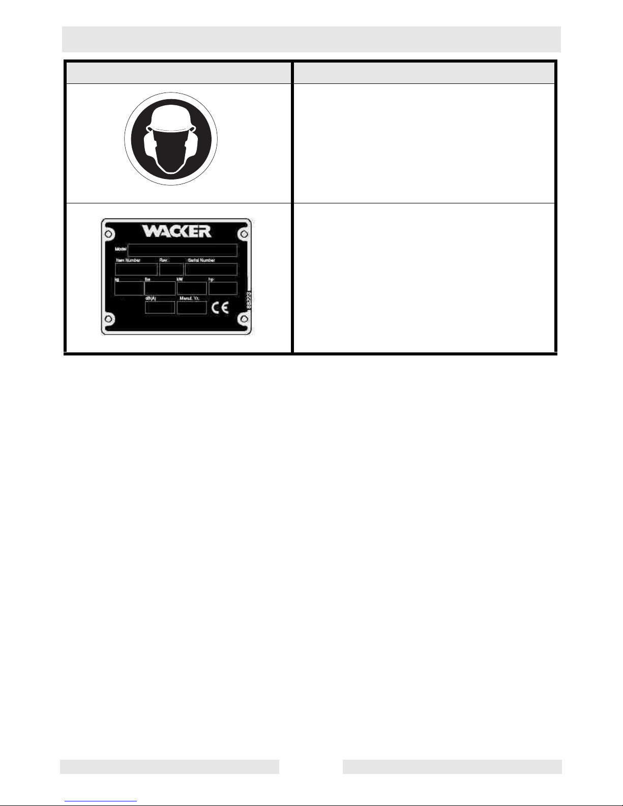
WARNING!
To prevent hearing loss, wear hearing protection when operating this machine.
A nameplate listing the Model Number, Item
Number, Revision, and Serial Number is
attached to each unit. Please record the information found on this plate so it will be available should the nameplate become lost or
damaged. When ordering parts or requesting
service information, you will alwa ys be asked
to specify the model, item number, revision
number, and serial number of the unit.
Label Meaning
wc_gr001475
Page 13

BPU 2950/2440 Repair Technical Data
wc_td000102gb.fm 9
2. Technical Data
2.1 Engine
2.2 Plate
Model
BPU
2440A
5904
BPU
2440A
7150
BPU
2440A
7867
BPU
2950R
5603
BPU
2950R
6222
6346
BPU
2950A
6412
6993
7872
7962
Engine
Engine Make Honda Honda Robin Robin Honda
Engine Model GX 140 GX 160 EY 27W W1-280 GX 240
Rated Power kW (Hp) 3.7 (5.0) 4.0 (5.5) 6 (8) 6 (8) 6 (8)
Operating Speed rpm 3600 3600 3550 3550 3550
Idle Speed rpm 1400 1400 1200 1200 1400
Clutch Engagement rpm 2100 2100 2100 2100 N/A
Cylinder Compression psi 85-121 85-121 N/A N/A 85-121
Valve Clearance
(cold)
intake
exhaust:
mm (in.)
0.15 (0.006)
0.20 (0.008)
0.15 (0.006)
0.20 (0.008)
0.10
(0.004)
0.10
(0.004)
0.10
(0.004)
0.10
(0.004)
0.15
(0.006)
0.20
(0.008)
Spark Plug Champion
RNYC
NGK
BPR6ES
Champion
L-86
Champion
L-86
Champion
RN9YC
Spark Plug Gap mm (in. ) 0.76 (0.030) 0.76 (0.030) 0.64
(0.025)
0.64
(0.025)
0.76
(0.030)
Air Cleaner type Pleated paper cartridge with oil wetted foam pre-cleaner
Fuel Tank Capacity liter (gal) 3.7 (1) 3.7 (1) 5.7 (1.5) 5.7 (1.5) 5.7 (1.5)
Model
BPU
2440A
5904
BPU
2440A
7150
BPU
2440A
7867
BPU
2950R
5603
BPU
2950R
6222
6346
BPU
2950A
6412
6993
7872
7962
Plate
Vibration Frequency VPM
(Hz)
5400
(90)
5400
(90)
5400
(90)
5400
(90)
5400
(90)
5400
(90)
Travel Speed m (ft.)/min 23 (75) 20 (65) 20 (65) 20 (65) 20 (65) 20 (65)
Power Take-Off kW (Hp) --- Centrifugal clutch & V-belt
Page 14
Technical Data BPU 2950/2440 Repair
wc_td000102gb.fm 10
2.3 Lubrication
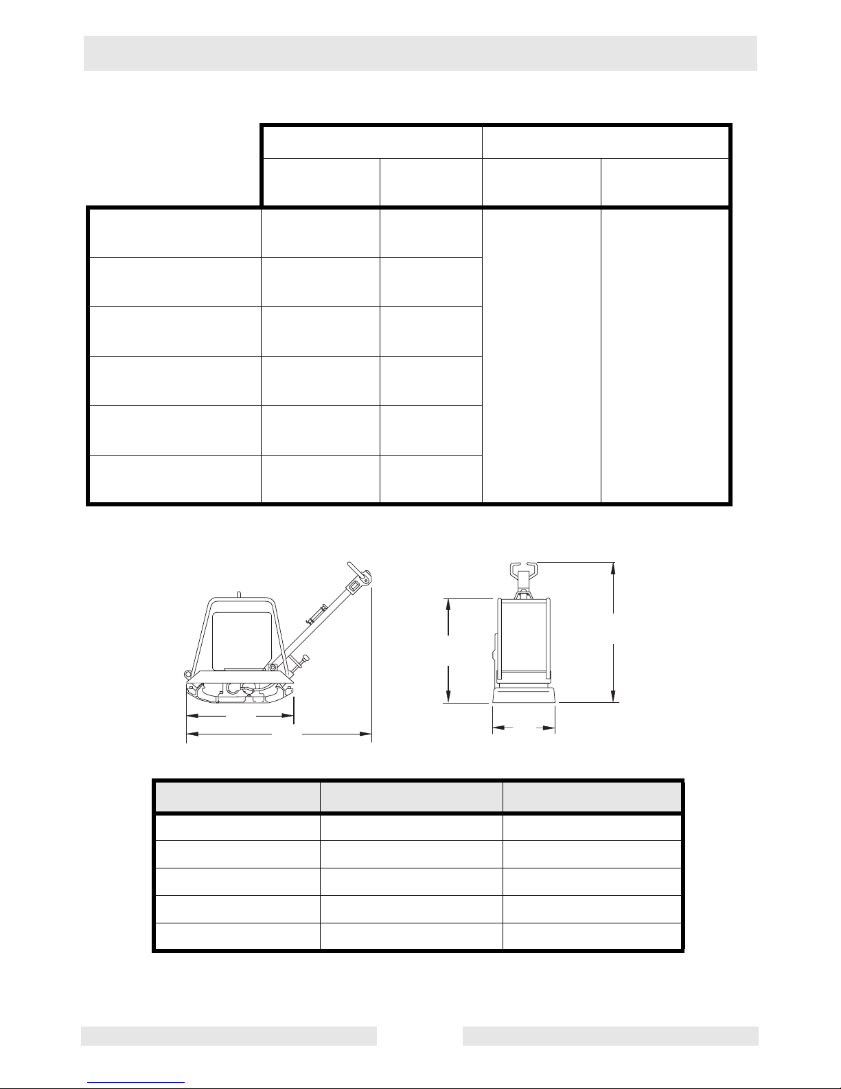
2.4 Dimensions
* Guide handle in working position
Engine Exciter
Model
(S/N)
Oil Grade
Quantity
ml (ounces)
Oil Grade
Quantity
ml (ounces)
BPU 2440A
(5904)
10W40 600 (20)
SAE 15W40 750 (25)
BPU 2440A
(7150)
10W30 600 (20)
BPU 2440A
(7867)
10W30 600 (20)
BPU 2650R
(5603)
10W030 770 (26)
BPU 2950R
(6222, 6346)
10W030 710 (24)
BPU 2950A
(6412)
10W40 1100 (37)
Dimension mm (in.) BPU 2950 BPU 2440
A 700 (27.5) 700 (27.5)
B 1380 (54) 1600 (63)
C 635 (26) 560 (22)
D 500 (19.5) 400 (15.5)
E* 1020 (40) 880 (35)
A
B
C
D
E
wc_gr001180
Page 15

BPU 2440/2950 Repair General Information
wc_tx000264gb.fm 11
3. General Information
3.1 Application
Due to its low width of only 400 or 500 mm and its infinite ly variable
working speed setting, this vibratory plate is particularly suited for all
kinds of soil compaction in confined areas such as in cable trenches
40 cm wide or more, compact ion of marginal stri ps, repairs on blackt op
surfaces as well as for all com paction jobs where the use of large scale
equipment is not suitable. Do not use this machine for any other
purpose.
3.2 Tools
Since all possible problems encountered while repairing the
equipment cannot be anticipated, it is up to the mechanic to use
common sense and good judgment in t ool selection.
The use of any spe cial tools is r ecommended only f or those operat ions
where the use of conventional tools proves inadequate.
Before substituting another tool or procedure, you should be satisfied
that neither personal injury nor damage to the component will result.
3.3 Ordering Parts
Operating / Parts Inf o r ma t i on
You must be familiar with the operation of this machine before you
attempt to trou bl es h oot or ma ke a ny re pa irs t o it. Ba sic op er atin g an d
maintenance procedures are described in the operator’s / parts
manual supplied with the machine. The operator’s / parts manual
should be kept with the machine. Use it to order replacement parts
when needed. If this manual becomes lost, please contact Wacker
Corporation to order a replacement.
Damage caused by misuse or neg lect of the unit should be brough t to
the attention of the operator, to prevent similar occurrences from
happening in the future.
Page 16
General Information BPU 2440/2950 Repair
wc_tx000264gb.fm 12
3.4 Reference Numbers ( )
Repair procedures contain reference numbers enclosed in
parentheses ( ). These numbers refer to the item numbers shown on
the assembly drawing s and other detaile d drawings. They are incl uded
to aid the mechanic in identifying parts and assembling components.
3.5 Weight Block
See Graphic: wc_gr000 84 3
The weight block symbol gives an approximate weight measurement
to aid the mechanic when lifting / hoisting larger components.
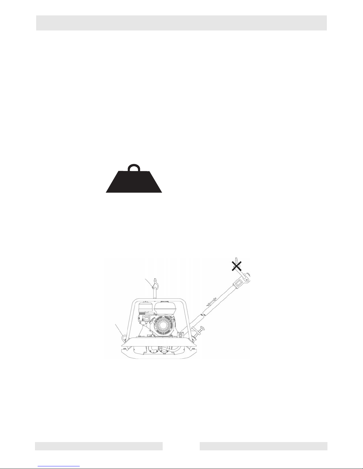
3.6 Lifting and Transporting the Machine
See Graphic: wc_gr000 98 6
Lift the machine only by the lifti ng eye (a). Do not lift the machine by
the control hand le. When liftin g, use a n approp riate cran e or hoi st with
minimum load-bearing capacity of 200 kg (440 lbs.).
When transporting the machine, secure it using the tie-down brackets
(b).
250 kg
(550 lbs.)
wc_gr000843
a
b
wc_gr000986
Page 17

BPU 2440/2950 Repair General Information
wc_tx000264gb.fm 13
Never lift or trans port the machine with its engine running.
3.7 Storage
Job Site Storage
Never allow the machine to sit overnight in a ditch, trench, or other low
area that may fill with water during heavy rain.
Long-term Storage
Before storing the unit for a long period of time, be sure it is in good
condition. The following steps are recommended before storing.
3.7.1 Completely drain the fuel tank. Run the engine until carburetor is dry.
3.7.2 Thoroughly clean ext erior of plate and engine. Visuall y inspect the uni t
for signs of damage, loose hardware, and worn shockmounts. Make
any necessary repair.
3.7.3 Change engine oil and exciter oil.
3.7.4 Clean area around spar k pl u g an d re m ove pl ug. Pou r 1 o un c e (3 0 m l)
of SAE 10W30 engine oil into engine cylinder throug h plug opening.
Crank engine slowly three or four times to distribute oil. Replace the
spark plug.
3.7.5 Store unit indoors in a clean dry area. If unit is to be stored outside,
wrap it with a quality tarpaulin.
CAUTION
CAUTION
Page 18

General Information BPU 2440/2950 Repair
wc_tx000264gb.fm 14
3.8 Theory of Operation
See Graphic: wc_gr000085 and wc_gr001430
The vibration required for compaction is produced by the exciter (a)
which is firmly joined to the l ower mass (b). The exciter contains two
shafts with eccentric weights attached to each shaft. The shafts are
connected by a sleeve gear and rotate in opposite directions. The
exciter is designed as a centr al vibrator with aligned vibrati ons. Such a
principle permits the direction of vi bration to be ch anged by rotating the
eccentric weights (c) in relation to one another. In this way, an infinitely
variable transition between vibration in forward motion, at standstill,
and in reverse motion is possible. This process is hydraulically
controlled with the operating control handle (d) on the center pole head
(e).
The drive engine (f) is anchored to the upper mass and drives the
exciter. The torque is transmitted by means of a friction connection
through the centrifugal clutch (g) and the exciter V-belt (h).
The centrifugal clutch interrupts flow of power to the exciter at low
engine speeds and thus permits perfect idling of the drive engine. The
speed of the drive engine can be infinitely varied by way of the throttle
control lever (i).
The upper and l ower (j) masse s are con nected t o each ot her by f our
vibration-damping shock mounts (k). This damping system prevents
the very high frequencies from being transmitted to the upper mass. As
a result, the functionality of the drive engine is retained in spite of the
high compaction performance.
The drive engine works according to the 4-stroke principle, is started
by way of a recoil starter, draws in combustion air over a dry air filter,
(l) and is air-cooled.
Page 19

BPU 2440/2950 Repair General Information
wc_tx000264gb.fm 15
l
f
d
e
k
a
j
b
i
h
g
wc_gr001430
wc_gr000085
c
Page 20

General Information BPU 2440/2950 Repair
wc_tx000264gb.fm 16
3.9 Directional and Speed Control
See Graphic: wc_gr001 43 1
The control lever (a) operates a hydraulically actuated piston which
connects to the sleeve gear inside the exciter. As the piston moves in
and out, the sleeve gear rot ates, changing th e position of th e eccentric
weights (c) inside the exciter . It is the position of the weights insid e the
exciter that determines the direction of travel.
1. Neutral: Wi th the ma chi ne running and no cont rol pr e ssur e applied,
the eccentric weights spin in phase and apply force in either the
upward or downward direction; each weight cancels any directional
force produced by the other. Due to the direction of rotation, the natural
tendency of the exciter is to shift into reverse. To prevent this from
happening, spring ten sion (c) in the ha ndle i s used to ap ply a con stant
pressure on the control circuit. The value of the spring is such that it
balances the exciter assembly in its neutral position. In neutral the
machine will vibrate but will not travel forward or reverse.
2. Forward: When the control lever is moved forward, hydraulic
pressure pushes against the actuating piston inside the exciter. As the
piston moves in, the pin riding inside the helix of the sleeve gear
rotates the gear which in turn rotates the rear weights away from the
neutral position. The we i ght s now r ota te out o f ph ase wi th each oth er .
While the forces of one set of weights lift the plate the forces from the
other set propel it forward. The farther the weights are shifted, the
faster the travel speed.
3. Reverse: When the control handle is released, the sleeve gear,
piston, and weights will automatically slip back into their neutral
position. If the control handle is pulled back past neutral, they continue
to slip until the piston reaches the end of its stroke and the weights
have shifted a full 90° in the opposite direction. In this position, the
plate will travel in reverse.
Speed: Top speed is achieved when the exciter weights are rotated a
full 90° in relation to each other. This occurs when the control lever is
shifted as far as possible in the forward or reverse direction.
Intermediate speeds are possi ble by partia lly shi fting th e contr ol le ver,
allowing the weigh ts to assume a positi on somewhere bet ween 0° and
90°.
Page 21

BPU 2440/2950 Repair General Information
wc_tx000264gb.fm 17
wc_gr001431
1
2
3
c
90˚
90˚
a
b
0˚
Page 22

General Information BPU 2440/2950 Repair
wc_tx000264gb.fm 18
3.10 Engine Speed and Machine Performance
Even a small rise or fall in engine speed will affect the centrifugal force
produced by the exciter. If the engine runs overspee d even slightly, the
centrifugal force will increase significantly and overload the exciter
bearings. If the engine runs underspeed, the centrifugal force will drop
significantly, causing poor compaction and slow travel speeds.
When checking engi ne speed, use a tac hometer for accur acy. Operate
the unit at the appropriate rpm. Refer to the
Technical Data
. Service
engine at recommended intervals and adjust drive belts regularly to
maintain ma x i mu m machine perf or m ance.
3.11 Operating on Slopes
See graphic: wc_gr0002 28
When compacting on a slope, only approach the slope from the top.
The operator mus t n eve r s ta nd bet we en t h e mac h ine an d dir ect ion of
descent.
Do not operate on a slope of more than 20°. If this degree of slope is
exceeded, a failure of the en gine’s splash-type lubricat ion system may
result.
wc_gr000228
Page 23

BPU 2440/2950 Repair General Information
wc_tx000264gb.fm 19
3.12 To Start
See graphic: wc_gr000014
3.12.1 Open fuel valve by moving lever to the right (a1).
Note:
If engine is cold, move choke lever to close position
(b1)
. If
engine is ho t, set choke to open position
(b2 )
.
3.12.2 Turn engine switch to “ON” (e1).
3.12.3 Open throttle by moving it slightly to left (d1).
3.12.4 Pull starter rope (c).
Note:
If the oil level in the engine is low, the engine will not start. If this
happens, add oil to engine. Some engines are equipped with an oil
alert light
(f)
that will come on while pulling the starter rope.
3.12.5 Open choke as engine warms (b2).
3.12.6 Open throttle fully to operate.
3.13 To Stop
See Graphic: wc_gr000014
3.13.1 Reduce engine RP M to idle by moving thro ttle complete ly to right (d2).
3.13.2 Turn engine switch to “OFF” (e2).
3.13.3 Close fuel valve by moving lever to the left (a2).
Page 24

Maintenance BPU 2440/2950 Repair
wc_tx000328gb.fm 20
4. Maintenance
4.1 General Maintenance
Periodic maintenance is essential to prolong the service life of the plate
and engine. Use the
Maintenance Schedu le
as a guide when servici ng
the equipment.
Compaction equipment is designed and manufactured to perform
heavy work under harsh operating conditions. Because of the heavy
demands, the frequency of engine maintenance may exceed that
recommended by the engine manufacturer.
For detailed maintena nce procedures of th e engine, refer to the en gine
manufacturer’s service manual.
Page 25

BPU 2440/2950 Repair Maintenance
wc_tx000328gb.fm 21
4.2 Maintenance Schedule
Daily
before
starting
Every
25
hrs.
Every
100
hrs.
Every
300
hrs.
Check engine oil level. •
Visually inspect exciter base for leaks. •
Inspect/clean air filter. Re-oil foam element;
replace as requ ired.
•
Check/tighten external hardware. •
Change engine oil. •
Inspect/adjust V-belt. •
Check/regap spark plug. Replace when
nececessary.
•
Clean engine cylinder cooling fins. •
Inspect shockmounts. Replace if cracked
or split.
•
Change exciter oil. •
Chang hydraulic oil in handle. •
Change fuel filter or strainer. •
Clean combustion chamber. •
Check/adjust breaker point ignitions. •
Clean/rinse fuel tank. •
Clean rewind starter. •
For new or reconditioned engines
:
Check/adjust belt tension. After first 5 hours of operation.
Change engine oil. After first 10 hours of operation.
Page 26

Maintenance BPU 2440/2950 Repair
wc_tx000328gb.fm 22
4.3 Air Filter
See graphic: wc_gr0014 32
4.3.1 Take off cover (a) and remove foam element (b).
4.3.2 Wash element with liq uid detergent (c) and ho t water. Rinse with clea n
water. Wrap in a clean towel and wring dry.
Do not use gasoline, paint thinner, or other low flash point solvent for
cleaning air cleaner element. A fire or explosion could result.
4.3.3 Saturate foam element with engine oil and squeeze out excess. If dirt
is severe, or element is torn or distorted, replace the element.
4.3.4 Clean paper cartridge (c) by blowing compressed air through the filter
from the inside or by ta pping ele ment on a hard surf ace. Use on ly light
air pressure to avoid tearing element. Replace paper cartridges as
necessary.
4.3.5 Re-install elements and cover.
4.3.6
Never operate ma chine with d amaged air clean er or missi ng air fi lters.
CAUTION
CAUTION
wc_gr001432
BPU 2950R
BPU 2950A/2440A
a
a
b
c
c
b
Page 27

BPU 2440/2950 Repair Maintenance
wc_tx000328gb.fm 23
4.4 Spark Pl ug
See Graphic: wc_gr000028
Clean or replace spark plug as needed to ensure proper operation.
Refer to the engine Owner’s Manual.
The muffler becom es very hot during oper ation a nd r emains h ot fo r a
while after stop ping the engine. Do not touc h the muffle r while it is hot.
Note:
Refer to the Technical Data for the recommended spark plug
type and the electrode gap setting.
4.4.1 Remove spark plug and inspect it.
4.4.2 Replace plug if the insulator is cracked or chipped.
4.4.3 Clean spark plug electrodes with a wire brush.
4.4.4 Se t the electrode gap (a).
4.4.5 Tighten spark plug securely.
CAUTION: A loose spark plug can become very hot and may cause
engine damage.
WARNING
Page 28

Maintenance BPU 2440/2950 Repair
wc_tx000328gb.fm 24
4.5 Cleaning Sediment Cup
See Graphic: wc_gr000 02 9
4.5.1 Turn fuel valve off.
4.5.2 Remove sediment cup (a) and O-ring (b).
4.5.3 Wash both thoroughly in a nonflammable solvent. Dry and reinstall
them.
4.5.4 Turn fuel valve on and check for leaks.
Page 29

BPU 2440/2950 Repair Maintenance
wc_tx000328gb.fm 25
4.6 Adjusting Idle Speed
See Graphic: wc_gr001122
Adjust engine to the no load or idle speed per the Technical Data.
4.6.1 Start the engine and allow it to warm up to normal operating
temperature.
4.6.2 Tur n the throt tle stop scre w (a) in to increas e spee d, out to decr ease
speed. Make sure the throttle lever is touching the stop screw before
measuring rpm.
4.7 Carburetor Adjustment
See Graphic: wc_gr0001061
The pilot screw (a) is fitted with a limiter cap to prevent excessive
enrichment of the air-fuel mixture in order to comply with emission
regulations. The mixtur e is set at the factor y and no adjustmen t should
be necessary. Do no t attempt to remove the l imiter cap. The l imiter cap
cannot be removed witho ut br ea kin g the pilot screw.
wc_gr001122
a
wc_gr001061
a
Page 30

Maintenance BPU 2440/2950 Repair
wc_tx000328gb.fm 26
4.8 Drive Belt
See graphic: wc_gr0014 3
Recommended tools:
Allen wrench—6 mm, Socket wrench—13 mm
See Maintenance Sched ule fo r servic e interva ls. On ne w mach ines or
after installing a new belt, check the belt tension after the first 5 hours
of operation.
Adjust belt for 1/4"–3/8" (5–10 mm) deflection when pressed midway
between the belt pulleys (x).
To tighten the belt, reduce the quantity of spacers (y) between the
pulley halves (z); to loosen, add spacers .
4.8.1 Remove belt cover.
4.8.2 Remove the four hex nuts holding the pulley halves together.
4.8.3 Remove the outer pulley half and remove spacers as required to
tighten the belt. Normally, removing one spacer is sufficient. When
installing a new belt, remove or add spacers as required to obtain
correct belt tension.
Note:
Place used spacers in equal quantities on either side of the
pulley to maintain bel t a l ig nm en t. If spacers cannot be placed equ all y ,
place odd spac er to the outside of pulley.
4.8.4 Secure pulley halves together with hex nuts and recheck belt tension.
Replace belt cover.
x
y
z
w
wc_gr001433
Page 31

BPU 2440/2950 Repair Maintenance
wc_tx000328gb.fm 27
4.9 Exciter Oil
See graphic: wc_gr001152
The bearings in the exciter assembly are splash lubricated and rotate
at a very high speed (u p to 5400 rpm). It is important to maint ain the
exciter oil at the proper level and change it regularly to ensure
maximum protecti on .
To drain oil, r emove drain pl ug an d tip ma chine t oward dr ain hol e. Use
a suction gun to draw oil out of the exciter case.
When filling, position plate on a level surface and add oil through drain
plug hole until oil is even with bottom edge of threads (a).
Caution: DO NOT overfill exciter case. Excessive wear on engine and
exciter bearings will result.
4.10 Control Circuit Oil
Check oil level in control handle once a week or every 25 hours.
Remove plug from top of control handle. Add oil as required to
maintain proper oil level. Oil level should be at “OEL” mark on outside
of housing. If oil needs replenishing on a regular basis, it may be
leaking past the seals on the pist ons. Service the seal s on the pisto ns.
A low oil level ma y allow ai r to en ter the co ntrol circui t. This condition
is normally characterized by the plate’s inability to travel in the forward
direction. Should this occur, bleed the system.
wc_gr001152
a
Page 32

Maintenance BPU 2440/2950 Repair
wc_tx000328gb.fm 28
4.11 Bleeding the Control Circuit
See graphic: wc_gr0014 35
Recommended Tool s:
Allen wrench – 6 mm
Socket or box wrench – 7 mm, 22 mm
Bleed control circu it wheneve r handl e or excite r have been opened for
service.
4.11.1 Turn off engine before servicing.
4.11.2 Lock handle in its vertical upright position.
4.11.3 Remove belt guard to expose exciter pulley (a).
4.11.4 Secure the control lever in the reverse position using a C-clamp to
prevent the spring and piston inside from popping out when control
assembly is removed. Remove control asse mbly from handle tube.
4.11.5 Fill handle tube with oil.
4.11.6 Remove bleeder screw (c) from cover flange on exciter.
4.11.7 Slowly rotate exciter pulley counterclockwise (same direction as
normal operation) two full turns. Oil will flow out of bleeder hole during
this procedure as the piston in the exciter extends and retracts inside
flange cover.
4.11.8 Rotate exciter pulley to a position where oil is observed flowing from
the hole and insert the bleed screw while holding the pulley in this
position. This prevents air fr om being drawn back into the flange cover.
Tighten the bleeder screw.
4.11.9 Top off oil in handle tube.
4.11.10 Make sure O-ring is in pla ce between control assembl y and tube flange
and re-install control lever assembly. Coat bolts with Loctite 242 or
equivalent and torque to 7 ft.lbs. (10 Nm).
4.11.11 Remove fill plug from control lever assembly and fill with oil to “OEL”
mark (b). Do not overfill.
4.11.12 Wait 30 seco nds for oil to fill area under piston, then remove
C-clamp and re-install fill plug.
4.11.13 Start plate and check directional control.
Page 33

BPU 2440/2950 Repair Maintenance
wc_tx000328gb.fm 29
4.12 Re-installing Piston in Control Assembly
See graphic: wc_gr001435
If it is ever necessary to re-install the piston into the control assembly,
carry out the following procedu r e.
4.12.1 Place the contro l lever in a position approx imately 45° to th e assemb ly
body. Insert the piston assembly until the first groove in the piston
catches on the pinion (d).
4.12.2 Move the lever to a position 90° to the assembly body. The pinion
should pull the piston into the assembly body as the lever is rotated.
When the lever reache s the 90° position, the end of the piston m ust be
flush with the opening in th e asse mbly bo dy (e). If it is not, repeat the
procedure, repositioning the piston as needed.
Ref. Description Ref. Description
1. Fill Plug 4. O-Ring
2. Spring 5. Seal
3. Piston 6. O-Ring
wc_gr001435
a
b
d
e
c
"OEL"
1
2
3
4
5
6
90˚
45˚
Page 34

Repair Procedures BPU 2440/2950 Repair
wc_tx000329gb.fm 30
5. Repair Procedures
5.1 General Repair
The repair procedures specify using sealants and screw and nut
adhesives to seal metal su rfaces and secure fasten ers in place. These
products must be used where indicated.
Although Loctite is referred to throughout this manual, an equivalent
sealant such as Hernon or Omnifit may be used. When using sealants,
always follow the application instructions on the container. Refer to the
thread locking and sealant char t lo cate d in this manual.
Most thread locking sealants break down at temperatures above
350°F (177°C). If a bolt or nut resists sepa ration , appl y heat to it usi ng
a small propane torch. When doing so, check to make sure no other
portion of the unit will be damaged from the use of the torch.
Correct torque values are listed whenever possible. Follow these
specifications when replacing or tightening screws and nuts. This is
especially important at sealed surfaces where screws must be
tightened evenly to ensure airtight seals thus preventing leaks.
The step-by-step procedures listed here provide complete descriptions
for the removal and replacement of all serviceable parts. However,
items such as bearings and shafts, assembled with press fits, should
be inspected for wear and damage while still in place. Removing or
installing such items often requires tools or presses to do the task
properly.
When installing bea rings into hou sing, apply p ressure only to the outer
race of the bear ing. I f pressing a bea ring ont o a shaf t, pressu re shou ld
be applied only to the inner race. Apply pressure evenly around the
bearing. Avoid using a hammer to pound bearings in place.
If using heat to fit a beari ng ont o a ra ce, u s e a ho t pl ate or hot oi l bat h
where the temperature can be controlled. Never heat a bearing using
a propane torch. Excessive heat, over 350°F (150°C), can affect the
hardness characteristics and tolerance values of the bearing.
Page 35

BPU 2440/2950 Repair Repair Procedures
wc_tx000329gb.fm 31
5.2 Checking Exciter Operation
Before servicing the exciter, check for other possible problems that
could affect machine operation, such as: engine speed, control circuit
operation, dr ive belt tightnes s, and clutch performance.
If the engine is running unders peed, the exciter VPM will be re duced,
the plate will handl e slug gishly an d pe rform poorly, and tr avel speed s
will be greatly reduced. Check engine speed with a tachometer. See
Technical Data
for correct engine speed.
If engine cannot be brough t up to spe ed, either the eng ine is at fa ult or
exciter bearings are binding. Check general condition of engine,
engine compression, and no-load operating speed.
5.2.1 To check bearings, run the machine with clutch engaged for several
minutes to warm exciter. Bearings may appear to turn freely when cold
but start to bind as they heat up. Stop engine and rotate the exciter by
hand.
Pinching hazard. Ke ep hands, feet, hair , and lo ose clothin g away fro m
moving parts.
5.2.2 Remove belt gu ard cover and ch eck operation o f drive belt, clu tch, and
exciter pulley. Use a vi bratio n tachome ter an d check e xciter VPM with
engine running at full throttle (3500–3600 rpm).
5.2.3 Air trapped in the control circuit will affect the plate’s ability to maintain
neutral position, or shift into forward. Make sure the system has been
properly bled, se als in handle are i n good condition, an d oil is at correct
level.
See Bleeding the Control Circuit.
5.2.4 If control system checks out but machine’s directional control still does
not operate correctly, the exciter’s actuating assembly is faulty or the
exciter timing is set incorrectly.
CAUTION
Page 36

Repair Procedures BPU 2440/2950 Repair
wc_tx000329gb.fm 32
5.3 Exciter Exploded View Illustration
wc_gr001436
10
11
12
13
14
15
4
7
2
2
3
1
4
5
6
7
8
9
16
17
4
22
21
20
19
18
4
4
33
32
31
21
20
30
29
28
27
26
25
4
24
23
Page 37

BPU 2440/2950 Repair Repair Procedures
wc_tx000329gb.fm 33
5.4 Exciter Parts List
See graphic: wc_gr001436
Ref. Description Ref. Description
1. Exciter housing 18. Idler gear
2. Screw M10x120 19. Idler shaft
3. Screw M10x35 20. Eccentric weight
4. Bearing (inner & outer race) 21. Washer
5. Bleed screw M4x5 22. Screw M10x35
6. Flanged cover 23. Retaining ring
7. Flanged cover 24. Wear ring
8. Washer 25. Retaining ring
9. Screw M6x20 26. Sleeve gear bearing
10. Pulley 27. Sleeve gear
11. Tolerance ring 28. Vent plug
12. Screw M6x16 29. Drive shaft
13. Holder 30. Guide pin
14. Flanged cover 31. Screw M10x25
15. Shaft seal 32. Piston assembly
16. Key 33. Piston seal
17. Retaining ring
Page 38

Repair Procedures BPU 2440/2950 Repair
wc_tx000329gb.fm 34
5.5 Removing Exciter
See graphic: wc_gr0013 47
Recommended Tool s:
Socket wrench – 19 mm
Allen wrench – 6 mm, 8 mm
Open-end wrench – 17 mm, 19 mm
Locking pliers
3-jaw puller
Rubber mallet
High-strength thread locking adhesive
Gasket eliminator
5.5.1 Turn machine’s engine off.
5.5.2 Remove belt guard and remove drive belt.
5.5.3 Using a 3-jaw puller (a), remove pulley (b) from exciter drive shaft.
5.5.4 Clamp the control line hose with locking pliers or C-clamp to prevent
leaking. Then, disconnect the line from the front exciter flange cover.
5.5.5 Using a 19 mm socket, remove the four hex nuts (c) that secure the
tubular frame (d) to the plate. Remove the frame from the plate.
5.5.6 Using an appropriate l ift or crane, lift the complete up per mass from the
baseplate to expose the exciter assembly.
5.5.7 Mark the exciter housing referencing the right hand front side (e).
5.5.8 Remove the eight socket head screws (f) securing exciter and lift the
exciter from the plate.
wc_gr001437
a
b
c
d
f
e
Page 39

BPU 2440/2950 Repair Repair Procedures
wc_tx000329gb.fm 35
5.6 Installing Exciter
See graphic: wc_gr001441
5.6.1 Scrape off old gasket m aterial and thorou ghly clean mounting su rfaces
on exciter and baseplate.
5.6.2 Once thoroughly clean and completely dry, coat mounting baseplate
(a) with Loctite 515 gasket eliminator or equivalent.
5.6.3 Position exciter assembly so that ex citer d rive pulley faces front right
corner (b) of plate.
5.6.4 Coat threads of mounting bo lts (c) with Loctite 242 o r equivalent, insert
them and torque to 36 ft.lbs. (49 Nm).
5.6.5 Inspect shockmounts (d). Replace any that appear w orn or damaged.
Coat threads of shockmou nt with Loctit e 242 or equi valent, inser t, and
torque to 63 ft.lbs. (86 Nm).
5.6.6 Position upper mass onto lower mass and secure with nuts. Torque
nuts to 63 ft.lbs. (86 Nm).
5.6.7 Install new tolerance ring (e) and carefully tap on exciter driv e pulley
(f) until it is flush against shaft shoulder.
5.6.8 Connect control hose and bleed the system.
5.6.9 Install drive belt. Adjust belt tension and check alignment of pulleys.
Replace belt guard cover.
5.6.10 Fill exciter (g) with oil.
a
g
c
d
b
e
f
wc_gr001441
Page 40

Repair Procedures BPU 2440/2950 Repair
wc_tx000329gb.fm 36
5.7 Exciter Assembly Cross Section
1
2
3
4
5
6
7
8
9
10
12a
12
13
11
14
15
27
23
26
25
24
16
5
2
17
18
19
20
21
22
wc_gr001442
Page 41

BPU 2440/2950 Repair Repair Procedures
wc_tx000329gb.fm 37
5.8 Exciter Cross Section List of Components
See Graphic: wc_gr001442
Ref. Description Ref. Description
1. Flange cover 14. Piston assembly
2. Idler shaft 15. Piston seal
3. Holder 16. Eccentric weight bolt (2)
4. Shaft seal 17. Flanged c ov er bolt (2)
5. Drive shaft 18. Roller bearing
6. Vent plug 19. Retaining ring
7. Retaining ring 20. Idler gear
8. Wear ring 21. Eccentric weight
9. Flanged cover 22. Shaft key
10. Retaining ring 23. Piston head
11. Guide pin 24. Retaining Ring
12. Sleeve gear 25. Bearing (2)
12a. Sleeve gear bearing 26. Washer
13. Flange cover 27. Screw
Page 42

Repair Procedures BPU 2440/2950 Repair
wc_tx000329gb.fm 38
5.9 Servicing Exciter
Recommended To ol s
Allen wrench – 5 mm, 8 mm
Snap ring pliers – external type
Torque wrench – 38 ft.lbs. (50 Nm)
Screwdriver
Rubber mallet
Arbor press
Wooden V-block
Loctite sealants – 242, 271, 515
5.10 Disassembling the Exciter
See graphics: wc_gr001443, wc_gr001444, wc_gr001445
Refer to Cross Section Component List for item nu mbers ( ).
Remove exciter as shown in section
Removing Exciter
.
5.10.1 Mark front corner of housing on side that exciter pulley attaches to.
5.10.2 Jam the gears to prevent them from turning and remove all exciter
weights (21).
5.10.3 Remove snap rings (7, 10) from drive shaft.
5.10.4 Mark location of a ll flange cover s (1, 2, 9, 13 ) and rem ove cove rs fr om
exciter.
Note:
Flange covers (9, 1 3) o n dr ive sh aft ar e eq uipped wit h threa ded
pusher holes (a)
.
5.10.5 Remove drive shaft (2).
Place exciter in an arbor press pulley side up. Press on pulley side of
drive shaft (b) until the shaft is pushed completely through the side of
the housing. The shaft will press out with sleeve gear (12), piston
assembly (14), and inner bearing races intact.
Note:
During this st ep the roller bearing on the op posite en d of shaft
will be pressed out of exciter housing. Remove bearing as it becomes
free of housing to prevent it from falling.
5.10.6 Use arbor press or 2-jaw puller to remove bearing races and sleeve
gear bearing (12a).
Page 43

BPU 2440/2950 Repair Repair Procedures
wc_tx000329gb.fm 39
5.10.7 Remove piston assem bly (15) from drive sh aft by placi ng on a wo oden
V-block (c). The block should ha ve a hole drilled in i t for the guide pi n
(11). Press guide pin (d) (DO NOT HAMMER) through shaft until
piston (e) can be removed.
Spin head (23) of piston assembly by hand and check condition of
small bearings (25) inside. H ead should rotate smoothly with no side
play. If necessary, remove retaining ring holding head and replace
bearings.
5.10.8 Press idler shaft from exciter.
5.10.9 Use an arbor press or puller to re move bearing race and idler ge ar
(20).
wc_gr001443
a
wc_gr001444
b
f
d
e
c
wc_gr001445
Page 44

Repair Procedures BPU 2440/2950 Repair
wc_tx000329gb.fm 40
5.11 Re-assembling the Exciter
Refer to Cross Section Component List for item nu mbers ( ).
See graphics: wc_gr00 14 46 and wc_g r 001 44 7
When installing shafts, make sure drive shaft is installed on machined
end of housin g. Later housing s are sy mmetric al and ar e mach ined at
all four bearing locations. On these housings, the drive shaft may be
installed on either side.
Installing idler shaft
5.11.1 Assemble retaining ring (19), key (22), gear (20), and bearing races
onto shaft.
5.11.2 Press roller bearing into one side of exciter housing. Use a flange
cover as a guide in positi oning the bearing the correct distance into the
housing.
5.11.3 Install the idler shaft. Complete the installation by pressing the
remaining bearing into the opposite side of housing. Position the
bearing into the housing using a flange cover.
Installing drive shaft
5.11.4 Using the wooden V-block to secure shaft, position the piston
assembly (14) in shaft and press guide pin (11) through.
Caution: Do not hammer on guide pi n. Hammering may mushroom
top of pin and cause it to bind in the sleeve gear.
Note:
When installing guide pin, make sure it extends an equal
distance on each side of shaft so it will slide freely once sleeve gear is
installed.
5.11.5 Press sleeve gear bearing (12a) on shaft and secure in place with
retaining ring (10).
5.11.6 Press bearing race on pulley side of shaft. Do not install bearing race
on opposite side of shaft until shaft and sleeve gear are in place.
5.11.7 Insert drive shaft a ssembly throu gh housing an d slide slee ve gear (12)
on shaft and over sleeve gear (12a).
Note:
Sleeve gear must be installed so th at when the pisto n assembly
is pulled out, the bolt holes in the shaft face the timing mark on the
gear.
5.11.8 Press bearing into pulley side of exciter housing. Position it in the
housing using a flanged cover.
Page 45

BPU 2440/2950 Repair Repair Procedures
wc_tx000329gb.fm 41
Procedure continued on next page.
Ref. Note
a. Drive shaft side machined surface
b. Pulley end of housing
c. Piston end of housing
d. Use flanged covers to position bearings the cor-
rect distance into exciter housing.
wc_gr001446
a
b
c
d
wc_gr001447
Page 46

Repair Procedures BPU 2440/2950 Repair
wc_tx000329gb.fm 42
Timing Exciter Weights
Refer to Cross Section Component List for item nu mbers ( ).
See graphics: wc_gr001448, wc_gr001449, and wc_gr001450.
5.11.9 Align timing marks on gears with piston extended. View shafts from
piston side and compare position of bolt holes in shafts and timing
marks on gears with those shown . If bolt pattern does not match slee ve
gear was installed incorrectly. Back gear off bearing and rotate it onehalf turn.
5.11.10 Install wear ring (17).
5.11.11 After installation is complete, operate piston by hand and make sure
both sleeve gear and piston slide freely.
5.11.12 Using Loctite 515 gasket eliminator or equ i val en t on flange, assemble
it to housing. Coat M10 screws with Loctite 242 or equivalent and
secure flange to housing. Torque screw to 7 ft.lbs. (10 Nm).
5.11.13 Install retaining ring (7) on end of drive shaft.
5.11.14 Once assembled, exciter weights can cause exciter shafts to turn
unexpectedly and with considerable force. Keep fingers and hands
away from gears and weights when handling exciter assembly to
prevent being pinched.
Install exciter weights. Coat threads of M10x25 screws with Loctite 271
or equivalent and secure weights to drive shaft. Coat threads of
M10x35 screws with Loctite 271 or equi valent and sec ure weights to
idler shaft. Torque screws to 38 ft.lbs, (50 Nm).
5.11.15 Re-install the exciter assembly to plate.
CAUTION
Page 47

BPU 2440/2950 Repair Repair Procedures
wc_tx000329gb.fm 43
Ref. Note
a. Bolt holes must face timing mark with piston
extended.
b. Piston
c. Position of exciter weights, piston fully extended.
View from piston side.
d Timing marks
e. Apply gasket eliminator to flange.
f. Idler shaft
g. Drive shaft
b
wc_gr001448
a
c
d
f
g
wc_gr001449
wc_gr001450
e
Page 48

Repair Procedures BPU 2440/2950 Repair
wc_tx000329gb.fm 44
5.12 Servicing the Clutch
See graphic: wc_gr0014 70
The engine clutch is ke yed (a) to the engine drive shaft (b) and secured
using a washer and hex screw. To replace clutch shoes or springs:
5.12.1 Remove snap ring (c) that secures bearing (d) to hub (e).
5.12.2 Pry behind clutch drum and rap center bolt with rubber mallet until the
drum and bearing are free from hub. It is not necessary to remove
clutch hub when replacing the clutch shoes or springs.
Although clutch hub is keyed to sha ft, it may bind tightly due to rust and
corrosion, making it difficult to remove. When installing a new clutch,
clean engine drive shaft and coat it with anti-seize lubricating
compound before before installing the new clutch.
Note:
Model 2440A also includes spacer (f).
a
c
b
d
f
e
wc_gr001470
Page 49

BPU 2440/2950 Repair Repair Procedures
wc_tx000329gb.fm 45
5.13 Replacing the Engine
Wacker BPU series reversible vibroplates are powered by Robin or
Honda engines in ei ther 5.0, 5.5, or 8 hp models . Replacing the e ngine
is similar for either type of engine; however, there are subtle
differences. Older plates have a beltguard mounted directly to the
engine. On newer models the beltguard is mounted to a baseplate that
is mounted to the upper mass.
Engine Removal
5.13.1 Remove the tubular frame from the plate.
5.13.2 Remove drive belt, pulley, and clutch from engine drive shaft.
5.13.3 On older models, remove the four bolts securing the beltguard to the
engine.
On newer models, remove the four bolts securing the beltguard to the
baseplate.
5.13.4 Remove engine mounting bolts and using an appropriate hoist or
crane, lift the engine off the upper mass.
Page 50

Repair Procedures BPU 2440/2950 Repair
wc_tx000329gb.fm 46
5.14 Engine Replacement—Honda
See graphic: wc_gr0014 71
5.14.1 U si ng an ap pr op riat e h oi st or c r an e to lif t en g ine , pl ace t he en gi ne on
the upper mass and secure th e engine with the four mou nting bolts (a).
Torque the bolts to 18 ft.lbs. (2 5 Nm) on BPU 244 0A models; 36 ft. lbs.
(49 Nm) on BPU 2950A models.
5.14.2 On older models, secure the beltguard to the engine using the four
mounting bolts.
On newer models, secur e the beltguard t o the baseplate usi ng the four
M10x25 mounting bolt s.
5.14.3 Coat engine drive shaft with anti-seize and re-install drive belt, pulley,
and clutch onto drive shaft.
5.14.4 Re-install tubular frame to upper mass.
Ref. Note
1. Baseplate
2. Upper Mass
3. Use Loctite 242 or equivalent on screw when installing.
4. Mounting bar
5. Lock nut
BPU 2440A
a
a
1
3
4
2
1
5
2
wc_gr001471
BPU 2950A
a
Page 51

BPU 2440/2950 Repair Repair Procedures
wc_tx000329gb.fm 47
5.15 Engine Replacement—Robin
See graphic: wc_gr001472
The engine hardware is designed to provide clearance between the
engine crankcase and the upper console. Any contact between the
console and the engine ma y str ess th e en gi ne bl ock. There should be
a small air gap between the engine and plate after hardware has been
tightened.
5.15.1 Place the cupped washer and flat washer as shown.
5.15.2 Using an appropriate hoist or crane, place the engine on the upper
mass and secure the engine with the four mounting bolts. Torque the
bolts to 38 ft.lbs (50 Nm).
5.15.3 On older models, secure the beltguard to the engine using the four
mounting bolts.
On newer models, secure the beltguard to the baseplate using the four
M10x25 mounting bolts.
5.15.4 Coat engine drive shaft with anti-seize and re-install drive belt, pulley,
and clutch onto drive shaft.
5.15.5 Re-install tubular frame to upper mass.
Ref. Note
1. Torque nut to 38 ft.lbs (50 Nm).
2. Check for air gap after as sembly.
3. Cupped washer
4. Flat washer
1
2
3
4
wc_gr001472
BPU 2950R
Page 52

Troubleshooting BPU 2440/2950 Repair
wc_tx000330gb.fm 48
6. Troubleshooting
Problem Cause Remedy
Engine runs, but no
vibration
Belt broken or loose.
Clutch not engaging.
Replace belt or adjust tension.
Inspect clutch for damage and repair.
Engine runs, but plate
does not develop full
speed.
Engine RPM set too low.
Throttle control not adjusted
correctly.
Soil conditions too wet, plate
bogging down.
Drive belt or clutch worn and
slipping.
Exciter pulley slipping.
Exciter gears not timed correctly.
Exciter bearings binding.
Adjust engine speed per manufacturer’s
recommendations.
Inspect throttle control and adjust rpm to 3600
at full throttle.
Review application.
Replace belt or clutch shoes.
Replace tolerance ring.
Remove exciter and adjust timing.
Check oil level in exciter and inspect exciter
bearings. Replace bearings if necessary.
Plate pulls to one side. Shockmounts damaged. Inspect and replace.
Plate travels in
reverse only
Air in control circuit.
Oil level low in handle.
Seals in handle leaking.
Seal on exciter piston leaking.
Bleed air from system.
Fill oil to level mark.
Replace seals.
Replace seal.
Forward and Reverse
switched
Exciter gears not timed correctly.
Sleeve gear installed incorrectly
on drive shaft.
Remove exciter and adjust gear timing.
Remove exciter and check position of sleeve
gear on drive shaft.
Directiona l control
inoperative
Piston binding in flange.
Sleeve gear binding on drive shaft.
Inspect piston assembly for damage. Repair or
replace.
Remove flange cover and operate piston by
hand to check operation of sleeve gear. Check
sleeve gear and guide pin.
Page 53

Threadlockers and Sealants
Threadlockers and Sealants
Threadlocking adhesives and sealants are specified throughout this
manual by a notation of “S” plus a number (S#) and should be used
where indicated. Threadlocking compounds normally break down at
temperatures above 175°C (350°F). If a screw or bolt is hard to
remove, heat it using a small propane torch to break down the sealant.
When applying sealant s, follow instru ctions on conta iner. The sealant s
listed below are recommended for use on Wacker equipment.
TYPE
( ) = Europe
COLOR USAGE
PART NO. SIZE
Loctite 222
Hernon 420
Omnifit 1150 (50M)
Purple Low strength, for locking threads smaller than 6 mm
(1/4").
Hand tool removable.
Temp. range, -54 to 149 ° C (-65 to 300 ° F)
73287 - 10 ml
Hernon 423
Omnifit 1350 (100M)
Blue Medium strength, for locking threads larger than
6 mm (1/4").
Hand tool removable.
Temp. range, -54 to 149 ° C (-65 to 300 ° F)
29311 - .5 ml
17380 - 50 ml
Loctite 271/277
Hernon 427
Omnifit 1550 (220M)
Red High strength, for all threads up to 25 mm (1”).
Heat parts before disassembly.
Temp. range, -54 to 149 ° C (-65 to 300 ° F)
29312 - .5 ml
26685 - 10 ml
73285 - 50 ml
Loctite 290
Hernon 431
Omnifit 1710 (230LL)
Green Medium to high strength, for locking preassembled
threads and for sealing weld porosity (wicking).
Gaps up to 0.13 mm (0.005")
Temp. range, -54 to 149 ° C (-65 to 300 ° F)
28824 - .5 ml
25316 - 10 ml
Loctite 609
Hernon 822
Omnifit 1730 (230L)
Green Medium strength retaining compound for slip or press
fit of shafts, bearings, gears, pulleys, etc.
Gaps up to 0.13 mm (0.005")
Temp. range, -54 to 149 ° C (-65 to 300 ° F)
29314 - .5 ml
Loctite 545
Hernon 947
Omnifit 1150 (50M)
Brown Hydraulic seala nt
Temp. range, -54 to 149 ° C (-65 to 300 ° F)
79356 - 50 ml
Loctite 592
Hernon 920
Omnifit 790
White Pipe sealant with Teflon for moderate pressures.
Temp. range, -54 to 149 ° C (-65 to 300 ° F)
26695 - 6 ml
73289 - 50 ml
Loctite 515
Hernon 910
Omnifit 10
Purple Form-in-place gasket for flexible joints.
Fills gaps up to 1.3 mm (0.05")
Temp. range, -54 to 149 ° C (-65 to 300 ° F)
70735 - 50 ml
Loctite 496
Hernon 110
Omnifit Sicomet 7000
Clear Instant adhesive for bonding rubber, metal and plas-
tics; general purpose.
For gaps up to 0.15 mm (0.006")
Read caution instruct io ns befo re using.
Temp. range, -54 to 82 ° C (-65 to 180 ° F)
52676 - 1 oz.
Page 54

Threadlockers and Sealants
Loctite Primer T
Hernon Primer 10
Omnifit VC Activator
Aerosol
Spray
Fast curing primer for threadlocking, retaining and
sealing compounds. Must be used with stainless
steel hardware. Recommended for use with gasket
sealants.
2006124 6 oz.
TYPE
( ) = Europe
COLOR USAGE
PART NO. SIZE
Page 55

Torque Values
Torque Values
Metric Fasteners (DIN)
TORQUE VALUES (Based on Bolt Size and Hardness) WRENCH SIZE
Size ft.lb. Nm ft.lb. Nm ft.lb. Nm Inch Metric Inch Metric
M3 *11 1.2 *14 1.6 *19 2.1 7/32 5.5 - 2.5
M4 *26 2.9 *36 4.1 *43 4.9 9/32 7 - 3
M5 *53 6.0 6 8.5 7 10 5/16 8 - 4
M6 7 10 10 14 13 17 - 10 - 5
M8 18 25 26 35 30 41 1/2 13 - 6
M10 36 49 51 69 61 83 11/16 17 - 8
M12 63 86 88 120 107 145 3/4 19 - 10
M14 99 135 140 190 169 230 7/8 22 - 12
M16 155 210 217 295 262 355 15/16 24 - 14
M18 214 290 298 405 357 485 1-1/16 27 - 14
M20 302 410 427 580 508 690 1-1/4 30 - 17
1 ft.lb. = 1.357 Nm. * = in.lb. 1 Inch = 25.4 mm
8.8
10.9 12.9
Page 56

Torque Values
Inch Fasteners (SAE)
Size ft.lb. Nm ft.lb. Nm ft.lb. Nm Inch Metric Inch Metric
No.4 *6 0.7 *14 1.0 *12 1.4 1/4 5.5 3/32 -
No.6 *12 1.4 *17 1.9 *21 2.4 5/16 8 7/64 -
No.8 *22 2.5 *31 3.5 *42 4.7 11/32 9 9/64 -
No.10 *323.6*455.1*606.83/8 - 5/32 -
1/4 6 8.1 9 12 12 16 7/16 - 3/32 -
5/16 13 18 19 26 24 33 1/2 13 1/4 -
3/8 23 31 33 45 43 58 9/16 - 5/16 -
7/16 37 50 52 71 69 94 5/8 16 3/8 -
1/2 57 77 80 109 105 142 3/4 19 3/8 -
9/16 82 111 115 156 158 214 13/16 - - -
5/8 112 152 159 216 195 265 15/16 24 1/2 -
3/4 200 271 282 383 353 479 1-1/8 - 5/8 -
1 ft.lb. = 1.357 Nm. * = in.lb. 1 Inch = 25.4 mm
Page 57

Page 58

Wacker Construction Equipment AG · Preußenstraße 41 · D-80809 München · Tel.: +49-(0)89-354 02 - 0 · Fax: +49 - (0)89-354 02-390
Wacker Corporation · P.O. Box 9007 · Menomonee Falls, WI 53052-9007 · Tel. : +1-(1)(262) 255-0500 · Fax: +1-(1)(262) 255-0550 · Tel. : (800) 770-0957
Wacker Asia Pacific Operations · Sunley Center, Unit 912, 9/F · 9 Wing Qin Street, Kwai Chung, N.T. · Hong Kong · Tel. + 852 2406 60 32 · Fax: + 852 2406 60 21
 Loading...