

Page 1
Air dehumidifier
AD ...
0211675en 001
10.2006
Operator's manual
Page 2

Page 3

3
Contents
1. Foreword 5
2. Control panel 6
3. Description 7
4. Operation 9
4.1 Installation .............................................................................................9
4.2 Using the machine .................................................................................9
5. Transport 11
6. Maintenance 12
7. Disposal 13
8. Malfunctions, causes and remedies 15
9. Electric wiring diagram 16
10. Technical data 18
EC Declaration of Conformity 19
Page 4

Contents
4
Page 5

5
Foreword
1. Foreword
This operator's manual contains information and procedures for the
safe operation and maintenance of your Wacker machine. In the interest of your own safety and to prevent accidents, you should carefully
read through the safety information, familiarize yourself with it and observe it at all times.
This operator's manual is not a manual for extensive maintenance and
repair work. Such work should be carried out by Wacker Service or authorized specialists.
The safety of the operator was one of the most important aspects taken into consideration when this machine was designed. Nevertheless,
improper use or incorrect maintenance can pose a risk. Please operate
and maintain your Wacker machine in accordance with the instructions
in this operator's manual. Your reward will be troublefree operation and
a high degree of availability.
Defective components should be replaced immediately!
Please contact your Wacker representative if you have any questions
concerning operation or maintenance.
All rights reserved, especially reproduction and distribution rights.
Copyright 2006 Wacker Construction Equipment AG
No part of this publication may be reproduced in any form or by any
means, electronic or mechanical, including photocopying, without the
expressed written permission of Wacker.
Any type of reproduction, distribution or storage on data media of any
type and form not authorized by Wacker represents an infringement of
copyright and will be prosecuted.
We expressly reserve the right to make technical modifications – even
without special notice – which aim at further improving our machines
or their safety standards.
Page 6

Control panel AD ...
wagtx5700000039en.fm 6
2. Control panel
a Main switch d Rotary control moisture meter
b Control lamp e Operating hour meter
c Control lamp "Water collecting
pan full" (not for AD 80)
Page 7
wagtx5700000011en.fm 7
AD ... Description
3. Description
The air dehumidifiers of the AD series are designed for use in rooms
and at locations that can be quickly dried or in which the relative humidity must not increase in an unregulated manner.
The air dehumidifiers of the AD series consist of a cooling circuit and
a fan and condense the water vapor present in the air. This reduces
the relative humidity.
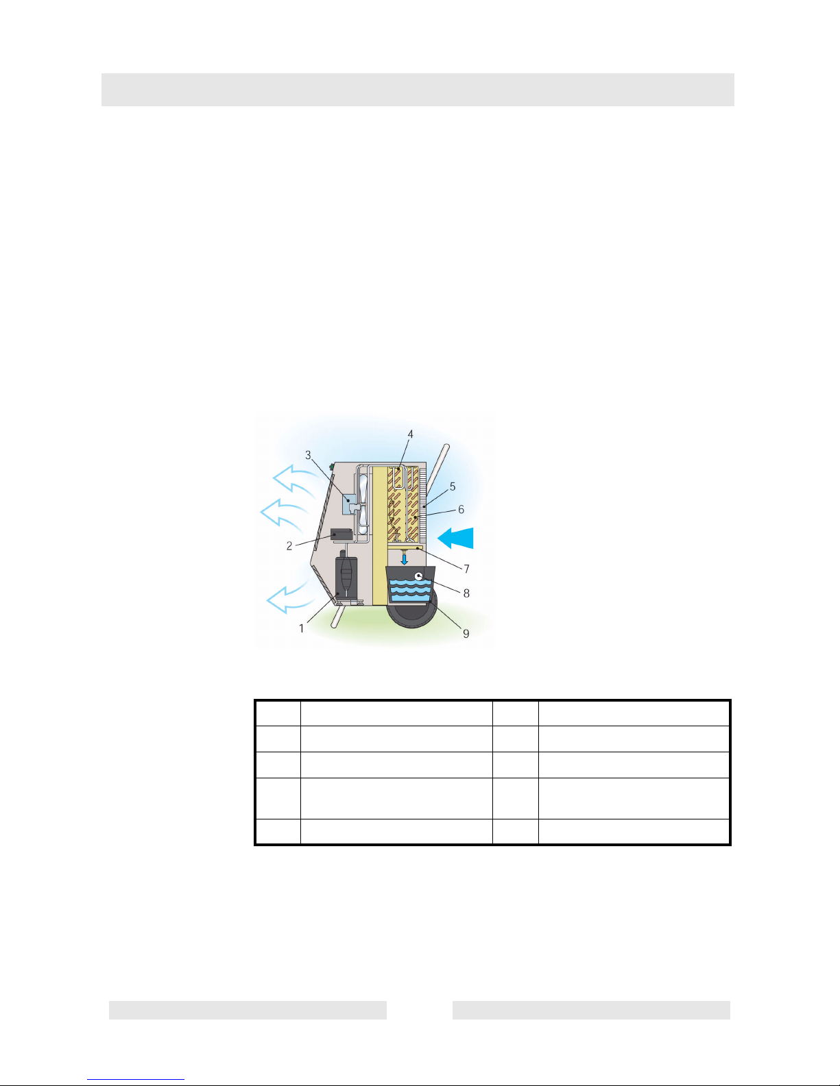
Figure 1 schematically illustrates the function of the machine. The air
drawn in by the fan (3) flows through the air filter (5) and against the
cold walls of the evaporator (6). This cools the air to a temperature that
is under the condensation point. A part of the vapor is condensed and
is collected in the water collection pan (9). Afterwards, the air flows
through the condenser (4) and is heated to a temperature that is slightly higher than the room temperature.
Figure 1: Function diagram
1 Hermetic compressor 6 Evaporator
2 Control unit 7 Condensate outlet
3 Fan 8 Float
4 Condenser 9 Water collecting pan (not for
AD 80)
5 Air filter
Page 8

Description AD ...
wagtx5700000011en.fm 8
For the most efficient and reliable operation, the humidity should be
between 40 % and 100 % and the temperature between 3 °C and
40 °C.
The moisture meter turns the air dehumidifier on automatically and
turns it automatically back off when the set limit value has been
reached. The control unit (2) turns the defrosting unit automatically on
and off if the operating conditions change. In addition, the machine is
turned off (fan and compressor switch off, control lamp (b) is lit) if a
malfunction occurs or if the machine overheats in a room that is too hot
(Tmax = 40 °C).
Caution
If the room temperature falls below the minimum level (3 °C), the air
dehumidifier does not function. The control lamp (b) will blink.
Page 9

wagtx5700000016en.fm 9
AD ... Operation
4. Operation
4.1 Installation
Caution
The mains for supplying power to the machine (230 V, single phase,
50 Hz) must be grounded and equipped with a fault current protective
switch.
Set up the air dehumidifier in the middle of the room to be dehumidified. The air suction side and the air discharge side must not be obstructed. The minimum distance from the walls should be 20 - 30 cm.
Do not set up the machine near heat sources (for example radiators,
ovens, heat outlets etc.) or near doors or openings. Doors and windows in the room must remain closed while the air dehumidifier is in
operation.
Caution
Do not place any rags or cloths on the air dehumidifier.
If required, you can conduct the water formed by dehumidification directly to a drain. To do this, remove the water collecting pan (9) and
connect a rubber hose to the condensate outlet (7).
4.2 Using the machine
4.2.1 Turning the machine on and off
Caution
Always keep the air dehumidifier in the vertical position (during operation, storage and, with model AD 22, during transport).
To turn on the air dehumidifier, proceed as follows:
* Turn the rotary control (d) of the moisture meter in the clockwise di-
rection to the marking "20 %".
* Set the green main switch (a) to the "ON" position. The fan and com-
pressor are turned on. The control lamp in the switch is lit.
Page 10

Operation AD ...
wagtx5700000016en.fm 10
Caution
The air dehumidifier is equipped with an automatic safety device. This
is why the compressor is turned on only 1 minute after you have
pressed the main switch (a).
* Turn the rotary control (d) of the moisture meter in the counterclock-
wise direction until you obtain the desired humidity.
To turn off the machine, set the green main switch (a) to the "OFF" position.
Caution
If the room temperature falls below the permissible level (3 °C), the air
dehumidifier will not function. The control lamp (b) will blink.
4.2.2 Water collecting pan (not for AD 80)
If the water collecting pan (9) is full, the air dehumidifier will switch off.
The control lamp (c) is lit. After you empty the pan, you can restart the
air dehumidifier.
Caution
Before you remove the water collecting pan, disconnect the machine
from the electric power supply. Set the main switch to the "OFF" position and pull the power plug from the electrical socket.
Caution
Carefully slide the water collecting pan back into the machine. This
helps prevent damage or inadvertent actuation of the switch connected
to the float.
Page 11

wagtx5700000020en.fm 11
AD ... Transport
5. Transport
Caution
Disconnect the machine from the electric power supply prior to transport. Set the main switch to the "OFF" position and pull the power plug
from the electrical socket.
During transport, do not store the air dehumidifier in the horizontal position.
Wind up the cable, take hold of the machine at the top handle and
transport on the wheels. Tilt the machine slightly and do not lift the machine.
Transporting the machine on stairs or on a steep incline is easier if you
hold the machine as shown in the figure:
Page 12

Maintenance AD ...
wagtx5700000023en.fm 12
6. Maintenance
Caution
Before you start maintenance procedures, disconnect the machine
from the electric power supply. Set the main switch to the "OFF" position and pull the power plug from the electrical socket.
To ensure trouble-free operation, clean the air filter and the internal
parts of the air dehumidifier on a regular basis. Blow out the air filter
with compressed air or wash it with a lukewarm soap solution. To clean
the internal parts, first disassemble the housing completely. Remove
the screws that connect the outer plates to the frame of the air dehumidifier. Clean the internal parts with a vacuum cleaner. In particular,
vacuum off the cooling fins of the condenser and evaporator.
Page 13

wagtx5700000007en.fm 13
AD ... Disposal
7. Disposal
The air dehumidifier has coolant R407C in the cooling circuit that is under pressure and oil in the compressor. When the machine has
reached the end of its service life, it must be disassembled and/or recycled or scrapped.
Caution
Only qualified personnel are permitted to carry out the steps described
in this section.
Do not allow the liquid coolants to escape in the atmosphere. To recycle the R407C, have the following on hand:
* Refilling unit (condenser unit)
* Pressure vessel
* Punch pliers
To recycle the R407C, proceed as follows:
* Connect the pressure vessel to the refilling unit and the refilling unit
to the punch pliers.
* Using the punch pliers, punch the outlet hose of the compressor.
* Open the valve on the refilling unit, turn on the refilling unit and drain
the cooling circuit.
* Turn off the refilling unit, close the suction and purging cocks of the
refilling unit as well as the cock of the pressure vessel.
* Remove the punch pliers.
* If the container is full with R407C: Bring it to a recycling point for
waste liquids.
Page 14

Disposal AD ...
wagtx5700000007en.fm 14
Remove the welded-on connectors of the purging and suction hoses
and loosen the fastening screws. Lift the compressor, drill a hole in the
bottom side of the housing and tip the machine to empty the oil into a
container or a barrel. Bring the container or the barrel to a recycling
point or waste disposal site for waste oil.
The remaining metallic parts contain copper, aluminum, and steel and
thus can be scrapped.
Page 15

wagtx5700000028en.fm 15
AD ... Malfunctions, causes and remedies
8. Malfunctions, causes and remedies
Malfunction Cause Remedy
The machine does not start
No electric power
Check the function and position
of the main switch
Check the ratings of the electrical power line (230 V 1 ~
50 Hz)
The moisture meter is incorrectly set
Set the moisture meter so that
the value is smaller than the
current value of the relative
humidity in the room
The machine does not start
Water collecting pan is full
(control lamp (c) is lit)
Empty the water collecting pan
Fan and compressor are in
operation but there is no formation of water and ice on the
evaporator
Insufficient air supply
Check if there are objects
obstructing the suction and discharge side
Check if there are any deposits
or incrustations on the filter or
on the cooling fins of the condenser or evaporator
Values for the temperature and
relative humidity are too low
Check if the temperature is
between 0 °C and 40 °C and if
the relative humidity is between
40 % and 100 %
The cooling circuit does not
function properly
Contact the Technical Customer Service
The machine has switched off,
and the control lamp (c) is lit
Water collecting pan is full Empty the water collecting pan
The machine has switched off
and the control lamp (b) is lit
(the cooling fins of the condenser have overheated)
Air flow path is obstructed Remove any obstructions and
turn the machine back on
Room temperature is over
40 °C
Do not start the machine until
the temperature has fallen
below 40 °C
The fan motor is defective Contact the Technical Cus-
tomer Service
The cooling circuit does not
function properly
Contact the Technical Customer Service
The machine has switched off,
and the control lamp (b) is lit
Temperature is below 3 °C Place the air dehumidifier in a
room that has a temperature of
3°C
Page 16

Electric wiring diagram AD ...
wagtx5700000033en.fm 16
9. Electric wiring diagram
MV Fan motor S1 Defrost probe S2 Overheating probe
S3 Sensor for the room tem-
perature
CP Compressor CO Condenser
FU Fuse (500 mA) IA Switch "Water collecting
pan full"
TI Operating hour meter
IG Main switch SA Control lamp "Water col-
lecting pan full"
SB Control lamp "Malfunc-
tion"
UM Moisture meter ST Control lamp "Voltage" EV Solenoid valve
AP Control unit TC Compressor thermostat RC Compressor relay
Page 17

wagtx5700000033en.fm 17
AD ... Electric wiring diagram
MV Fan motor S1 Defrost probe S2 Overheating probe
S3 Sensor for the room tem-
perature
CP Compressor CO Condenser
FU Fuse (500 mA) TI Operating hour meter IG Main switch
SA Control lamp "Water col-
lecting pan full"
SB Control lamp "Malfunc-
tion"
UM Moisture meter
ST Control lamp "Voltage" EV Solenoid valve AP Control unit
TC Compressor thermostat
Page 18

Technical data AD ...
wagtd5700000006en.fm 18
10. Technical data
Unit AD 22 AD 52 AD 80
Item number 0610130 0610131
0610139
0610132
0610140
Relative humidity
1
1. Work area
[%] 40 – 100
Temperature
1
[°C] 3 – 40
Air flow performance [m³/h] 250 650 900
Dehumidifying perfor-
mance
2
2. T = 30 °C; UR = 80 %
[l/24h] 22 52 80
Coolant R407C
Amount of coolant [g] 300 525 1600
Voltage [V] 230 1~
Frequency [Hz] 50
Current consumption
2
[W] 550 1000 1350
Noise level, SPL [dBA] 59 65 64
Tank capacity [l] 5 11 —
Dimensions, L x B x H [mm] 540 x 585 x 775 650 x 615 x 958 761 x 776 x 1048
Weight [kg] 39 52 76
Page 19

EC Declaration of Conformity
Wacker Construction Equipment AG, Preußenstraße 41, 80809 München
certifies that the construction machine:
Type:
Air dehumidifier
fulfill the requirements of the directive 89/392/EC with amendments 91/368, 93/44,
93/68 and 98/37.
The machine was constructed in accordance with the following directives:
89/336/EC
92/31/EC
73/23/EC
Type AD 22 AD 52 AD 80
Machine type number 0610130 0610131
0610139
0610132
0610140
Installed electrical output [W] 550 1000 1350
Dr. Stenzel
Head of Research and Development
Please keep this document in a safe place
Page 20

Wacker Construction Equipment AG - Preußenstraße 41 - 80809 München - Tel.: +49-(0)89-3 54 02-0 - Fax: +49-(0)89-3 54 02-390
Wacker Corporation - P.O. Box 9007 - Menomonee Falls, WI 53052-9007 - Tel.: +1 (1) 262-255-0500 - Fax: +1 (1) 262-255-0550 - Tel.: 800-770-0957
Wacker Machinery Ltd.- Skyline Tower, Suite 2303, 23/F, 39 Wang Kwong Road, Kowloon Bay, Hong Kong -Tel.: +852 2406 6032 -Fax: +852 2406 6021
Page 21

Page 22

 Loading...