

Page 1

Operator’s Manual
Compact loaders
901S/901SP
1101C/1101CP
Machine models S03-01 (901s/901sp)
S03-02 (1101c/1101cp)
Edition 2.1
Article number 1000185550
Language en
Page 2

Documentation
Documentation Order no.
Operator’s manual 1000185550
Spare parts catalog de/en/fr (901) 1000187499
Spare parts catalog de/en/fr (1101) 1000187759
Spare parts catalog de/it/es (901) 1000187501
Spare parts catalog de/it/es (1101) 1000187760
Legend
Original Operator’s Manual x
Translation of original Operator’s
Manual
--
Edition 2.1
Date 12/2014
Document BA 901/1101 en
Copyright © 2014 Wacker Neuson Linz GmbH, Hörsching
Printed in Austria
All rights reserved, in particular the copyright, the right of reproduction and the right of distribution applicable worldwide.
No part of this publication may be reproduced, translated or used in any form or by any means – graphic, electronic or mechanical including photocopying, recording, taping or information storage or retrieval systems – without prior permission in writing from the manufacturer.
No reproduction or translation of this publication, in whole or part, without the written consent of Wacker Neuson Linz GmbH.
Violations of legal regulations, in particular of the copyright protection, will be subject to civil and criminal prosecution.
Wacker Neuson Linz GmbH keep abreast of the latest technical developments and constantly improve their products. For this reason, we
may from time to time need to make changes to figures and descriptions in this documentation which do not reflect products that have
already been delivered and that will not be implemented on these machines.
Technical data, dimensions and weights are only given as an indication. Responsibility for errors or omissions not accepted.
Photographs and graphics are symbolic representations and may differ from the actual products.
The cover features the machine with possible optional equipment.
Wacker Neuson Linz GmbH
Flughafenstr. 7
A-4063 Hörsching
Page 3

Table of contents
Table of contents
Table of contents
I
Introduction
Important information on this Operator’s Manual ..................................................... 1-1
Machine overview .................................................................................................... 1-2
Brief description ....................................................................................................... 1-3
Traveling drive ................................................................................................... 1-3
Operating hydraulics .......................................................................................... 1-3
Cooling system .................................................................................................. 1-3
Cabin (ROPS and FOPS) .................................................................................. 1-4
Fields of application, attachments ........................................................................... 1-5
Use: attachment ................................................................................................ 1-6
Regulations .............................................................................................................. 1-7
Declaration of conformity 901s .......................................................................... 1-8
Declaration of conformity 901sp ........................................................................ 1-9
Declaration of conformity 1101c ...................................................................... 1-10
Declaration of conformity 1101cp .................................................................... 1-11
Type labels and component numbers .................................................................... 1-12
Serial number .................................................................................................. 1-12
Signs and symbols ................................................................................................. 1-15
Warning and safety labels ............................................................................... 1-15
Operation and information labels ..................................................................... 1-19
Model 901: ....................................................................................................... 1-20
Options: ........................................................................................................... 1-21
Fire extinguisher .................................................................................................... 1-23
Duty to wear ear protectors ................................................................................... 1-23
Safety instructions
Identification of warnings and dangers .................................................................... 2-1
Warranty .................................................................................................................. 2-1
Designated use and exemption from liability ........................................................... 2-2
General conduct and safety instructions .................................................................. 2-3
Organizational measures ................................................................................... 2-3
Selection and qualification of personnel, basic responsibilities ......................... 2-4
Safety instructions regarding operation ................................................................... 2-5
Normal operation ............................................................................................... 2-5
Applications with lifting gear .............................................................................. 2-6
Trailers and attachments ................................................................................... 2-7
Transportation ................................................................................................... 2-7
Safety instructions for maintenance ......................................................................... 2-8
Warning of special hazards ................................................................................... 2-10
Electrical energy .............................................................................................. 2-10
Gas, dust, steam, smoke ................................................................................. 2-10
Hydraulic system ............................................................................................. 2-10
Noise ............................................................................................................... 2-11
Oil, grease and other chemical substances ..................................................... 2-11
Battery ............................................................................................................. 2-11
Tires (model 901) ............................................................................................ 2-11
Tracks (model 1101) ........................................................................................ 2-11
Operation
BA 901/1101 en - Edition 2.1 * Ba91101en2_1IVZ.fm I-1
Page 4

Table of contents
Cabin overview (models 901/1101) ......................................................................... 3-2
Cabin (models 901/1101): legend ............................................................................ 3-3
Instrument panel overview ....................................................................................... 3-4
Instrument panel legend .......................................................................................... 3-6
Indicator lights and warning lights (overview) ......................................................... 3-7
Putting into operation ............................................................................................. 3-10
Safety instructions ........................................................................................... 3-10
Putting into operation for the first time ............................................................. 3-10
Running-in period ............................................................................................ 3-10
Check lists ....................................................................................................... 3-11
Start-up checklist ............................................................................................. 3-11
Operation checklist .......................................................................................... 3-12
Parking checklist .............................................................................................. 3-12
Performing machine travel ..................................................................................... 3-13
Preheating start switch (overview) ................................................................... 3-13
Accelerator actuation ....................................................................................... 3-13
Speed control (option) ..................................................................................... 3-14
Parking brake ................................................................................................... 3-14
Brake test ......................................................................................................... 3-14
Before starting the engine ................................................................................ 3-15
Starting the engine: general ............................................................................. 3-16
Starting ............................................................................................................ 3-17
Starting with the immobilizer (option) ............................................................... 3-18
Jump-starting the engine (supply battery) ....................................................... 3-19
Battery master switch ............................................................................................. 3-20
When the engine has started ... ....................................................................... 3-20
Starting at low temperatures ............................................................................ 3-21
Engine warm-up ............................................................................................... 3-21
Machine travel on public roads .............................................................................. 3-22
Preparing machine travel on public roads ....................................................... 3-22
Starting machine travel .......................................................................................... 3-25
Reversing ......................................................................................................... 3-25
Control levers ................................................................................................... 3-26
ISO controls ..................................................................................................... 3-27
H controls (option) ........................................................................................... 3-28
Hydrostatic service brake ................................................................................ 3-29
Parking brake ................................................................................................... 3-29
Machine travel on slopes ....................................................................................... 3-30
Specific safety instructions .............................................................................. 3-30
Machine operation on rough terrain ................................................................. 3-31
Machine travel on slopes ................................................................................. 3-31
Parking the machine .............................................................................................. 3-32
Parking the machine on slopes ........................................................................ 3-32
2nd speed .............................................................................................................. 3-33
Horn ....................................................................................................................... 3-33
Light system ........................................................................................................... 3-34
Lights (option) .................................................................................................. 3-34
Turn indicators (option) .................................................................................... 3-34
Hazard warning system (option) ...................................................................... 3-35
Working lights (option) ..................................................................................... 3-36
Rotating beacon (option) ................................................................................. 3-36
Washer system (option) ......................................................................................... 3-37
Washer system reservoir ................................................................................. 3-37
Ventilation (fully-glazed cabin option) .................................................................... 3-38
Cabin heating and ventilation .......................................................................... 3-38
Summer/winter operation ................................................................................. 3-38
I-2 BA 901/1101 en - Edition 2.1 * Ba91101en2_1IVZ.fm
Page 5

Table of contents
Air conditioning (option) ......................................................................................... 3-39
Recirculated air mode ...................................................................................... 3-39
Seat adjustment, safety bars and seat belt ............................................................ 3-40
Seat adjustment ............................................................................................... 3-40
Weight adjustment ........................................................................................... 3-40
Horizontal adjustment ...................................................................................... 3-41
Safety bars ...................................................................................................... 3-42
Seat belt .......................................................................................................... 3-43
Emergency exit ...................................................................................................... 3-44
Engine cover .......................................................................................................... 3-44
Maintenance flap ................................................................................................... 3-45
Cabin ..................................................................................................................... 3-46
Raising/lowering the cabin ............................................................................... 3-46
Cabin entry and exit ......................................................................................... 3-48
Cabin access and exit (fully-glazed cabin option) ........................................... 3-49
Front window (with cabin option) ..................................................................... 3-50
Towing and transporting the machine .................................................................... 3-51
Towing ............................................................................................................. 3-51
Loading and transporting the machine ............................................................ 3-52
Tying down the machine .................................................................................. 3-53
Crane-lifting the machine ................................................................................. 3-54
Crane-lifting bracket (option) ........................................................................... 3-54
Control levers (ISO controls) (overview) ................................................................ 3-55
Locking the operating hydraulics (option) ........................................................ 3-55
Control lever (ISO controls) ............................................................................. 3-55
Lowering the loader unit with the engine stopped ........................................... 3-56
Control lever (H controls) (overview) ..................................................................... 3-57
Locking the operating hydraulics (option) ........................................................ 3-57
Control lever (H controls) ................................................................................. 3-57
Lowering the loader unit with the engine stopped ........................................... 3-58
Parallel bucket lift ................................................................................................... 3-58
2-way parallel bucket lift (option) ........................................................................... 3-58
Attachment controls (option) .................................................................................. 3-59
Load stabilizer ........................................................................................................ 3-59
Auxiliary hydraulics pedal ...................................................................................... 3-59
Auxiliary hydraulics pedal cover ...................................................................... 3-60
Releasing the pressure on the quick couplers on the loader unit .......................... 3-60
Couplings ............................................................................................................... 3-60
Connections for auxiliary hydraulics ...................................................................... 3-61
3rd control circuit (option) ...................................................................................... 3-61
Re-equipping the loader unit .................................................................................. 3-62
Fitting attachments onto the quickhitch ........................................................... 3-62
Hydraulic quickhitch (option) .................................................................................. 3-63
Machine operation ................................................................................................. 3-64
General safety instructions .............................................................................. 3-64
Transporting with a full bucket ......................................................................... 3-65
Attachments ........................................................................................................... 3-69
Standard Bucket .............................................................................................. 3-69
Excavation bucket ........................................................................................... 3-70
Multipurpose bucket ........................................................................................ 3-70
Lightweight material bucket ............................................................................. 3-71
“4-in-1” bucket ................................................................................................. 3-71
“4-in-1” bucket with teeth ................................................................................. 3-72
Rotary broom ................................................................................................... 3-72
Multipurpose bucket ........................................................................................ 3-73
Agricultural grab .............................................................................................. 3-73
Pallet forks ....................................................................................................... 3-74
BA 901/1101 en - Edition 2.1 * Ba91101en2_1IVZ.fm I-3
Page 6

Table of contents
Hammer operation ................................................................................................. 3-75
Installing a hydraulic hammer on the mount .................................................... 3-75
Malfunctions
Engine malfunctions ................................................................................................. 4-1
Maintenance
Introduction .............................................................................................................. 5-1
Fuel system .............................................................................................................. 5-2
Specific safety instructions ................................................................................ 5-2
Draining fuel ....................................................................................................... 5-2
Refueling ............................................................................................................ 5-2
Stationary fuel pumps ........................................................................................ 5-3
Diesel fuel specification ..................................................................................... 5-3
Bleeding the fuel system .................................................................................... 5-4
Fuel prefilter with water separator ..................................................................... 5-4
Engine lubrication system ........................................................................................ 5-5
Checking the oil level ......................................................................................... 5-5
Adding engine oil ............................................................................................... 5-6
Engine and hydraulics cooling system ..................................................................... 5-7
Specific safety instructions ................................................................................ 5-7
Checking the coolant level/adding coolant ........................................................ 5-8
Air filter ................................................................................................................... 5-10
Replacing the filter ........................................................................................... 5-11
V-belts .................................................................................................................... 5-12
Checking V-belt tension ................................................................................... 5-12
Retightening the V-belts .................................................................................. 5-13
Checking the V-belt of the air conditioning system (option) ............................. 5-14
Tightening the V-belt of the air conditioning system (option) ........................... 5-14
Hydraulic system .................................................................................................... 5-15
Specific safety instructions .............................................................................. 5-15
Checking the hydraulic oil level ....................................................................... 5-15
Adding hydraulic oil .......................................................................................... 5-17
Checking hydraulic pressure lines ................................................................... 5-18
Travel gear maintenance ....................................................................................... 5-19
Checking drive chain oil (model 901) ..................................................................... 5-20
Checking the oil level ....................................................................................... 5-20
Checking drive chain tension (model 901) ............................................................. 5-21
Checking track tension .................................................................................... 5-21
Tires (model 901) ................................................................................................... 5-22
Raising and jacking up the machine ................................................................ 5-22
Fitting the wheels ............................................................................................. 5-23
Airboss tires (option) ........................................................................................ 5-23
Tracks (model 1101) .............................................................................................. 5-24
Checking track tension .................................................................................... 5-24
Adjusting track tension ..................................................................................... 5-25
Replacing tracks .................................................................................................... 5-26
Traveling drive ....................................................................................................... 5-26
Checking the oil level and adding oil ............................................................... 5-26
Draining oil ....................................................................................................... 5-27
Electrical system .................................................................................................... 5-27
Specific safety instructions .............................................................................. 5-27
Servicing and maintenance at regular intervals ............................................... 5-28
Instructions concerning specific components .................................................. 5-28
Alternator ......................................................................................................... 5-28
Battery .................................................................................................................... 5-29
General maintenance ............................................................................................. 5-30
Cleaning ........................................................................................................... 5-30
I-4 BA 901/1101 en - Edition 2.1 * Ba91101en2_1IVZ.fm
Page 7

Table of contents
General instructions for all areas of the machine ............................................ 5-30
Inside the cabin ............................................................................................... 5-31
Under the cabin ............................................................................................... 5-31
Exterior of the machine .................................................................................... 5-31
Engine compartment ....................................................................................... 5-31
Rear window .................................................................................................... 5-32
Threaded fittings and attachments .................................................................. 5-32
Pivots and hinges ............................................................................................ 5-32
Maintenance of attachments ........................................................................... 5-32
Maintenance prop of loader unit ...................................................................... 5-33
Maintenance if the machine is out of service for a longer period of time ............... 5-34
Preparatory work before taking out of service ................................................. 5-34
Putting into operation again ............................................................................. 5-34
Fluids and lubricants .............................................................................................. 5-35
Maintenance plan (overview) ................................................................................. 5-37
Maintenance label .................................................................................................. 5-40
Explanation of symbols on the maintenance label ......................................... 5-40
Maintenance plan (model 901) ........................................................................ 5-41
Maintenance plan (model 1101) ...................................................................... 5-42
Technical data
Chassis .................................................................................................................... 6-1
Engine ...................................................................................................................... 6-1
Traveling drive ......................................................................................................... 6-2
Brakes ...................................................................................................................... 6-2
Operating hydraulics ................................................................................................ 6-3
Pilot control .............................................................................................................. 6-3
High Flow additional control circuit .......................................................................... 6-3
Electrical system ...................................................................................................... 6-4
Fuse box behind the seat on the left ................................................................. 6-4
Main fuse box with relays .................................................................................. 6-5
Relay box at rear left of cabin ............................................................................ 6-5
Tires (model 901) ..................................................................................................... 6-6
Tracks (model 1101) ................................................................................................ 6-6
Noise levels ............................................................................................................. 6-6
Vibration ................................................................................................................... 6-7
Coolant compound table ........................................................................................ 6-10
Weights .................................................................................................................. 6-10
Weight of options (selection) ........................................................................... 6-10
Dimensions model 901 .......................................................................................... 6-11
Dimensions model 1101 ........................................................................................ 6-12
BA 901/1101 en - Edition 2.1 * Ba91101en2_1IVZ.fm I-5
Page 8

Index
Index
I
A
Abbreviations .........................................................................................1-1
Accelerator actuation ...........................................................................3-13
Air filter .................................................................................................5-10
Applications with lifting gear ..................................................................2-6
Attachments .........................................................................................3-69
B
Battery master switch ..........................................................................3-20
Brake test .............................................................................................3-14
C
Check lists ...........................................................................................3-11
Checking track tension ........................................................................5-24
Crane-lifting the machine .....................................................................3-54
D
Declaration of conformity 1101c ..........................................................1-10
Declaration of conformity 1101cp ........................................................1-11
Declaration of conformity 901s ..............................................................1-8
Declaration of conformity 901sp ............................................................1-9
Designated use and exemption from liability .........................................2-2
F
Fire extinguisher ..................................................................................1-23
Fluids and lubricants ............................................................................5-35
I
Important information
On this Operator’s Manual ..............................................................1-1
Indicator lights and warning lights ..........................................................3-7
L
Legal regulations ...................................................................................1-7
Light system .........................................................................................3-34
Loading and transporting .....................................................................3-52
Lowering the loader unit with the engine stopped ..................... 3-56, 3-58
M
Machine
Brief description .............................................................................. 1-3
Fields of application ........................................................................ 1-5
Overview ........................................................................................ 1-2
Machine travel on public roads ........................................................... 3-22
Maintenance
Adding coolant ................................................................................ 5-8
Adding engine oil ............................................................................ 5-6
Adding hydraulic oil ...................................................................... 5-17
Air filter ......................................................................................... 5-11
Bleeding the fuel system ................................................................ 5-4
Checking drive chain oil level ....................................................... 5-20
Checking drive chain tension ....................................................... 5-21
Checking the coolant level ............................................................. 5-8
Checking the engine oil level .................................................5-5, 5-20
Checking the hydraulic oil level .................................................... 5-15
Cleaning ....................................................................................... 5-30
Electrical system .......................................................................... 5-27
Engine and hydraulics cooling system ........................................... 5-7
Engine lubrication system .............................................................. 5-5
Fluids and lubricants .................................................................... 5-35
Fuel system .................................................................................... 5-2
General maintenance ................................................................... 5-30
Hydraulic pressure lines ...............................................................5-18
Hydraulic system .......................................................................... 5-15
Instructions concerning specific components ............................... 5-28
Maintenance plan ......................................................................... 5-37
Pivots and hinges ......................................................................... 5-32
Servicing and maintenance at regular intervals ........................... 5-28
Threaded fittings ........................................................................... 5-32
N
Noise levels ......................................................................................... 1-21
O
Operation .............................................................................................. 3-1
Before starting the engine ............................................................ 3-15
Cabin model 501s (overview) ......................................................... 3-2
Instrument panel overview ............................................................. 3-4
Parking the machine ..................................................................... 3-32
Seat belt ....................................................................................... 3-43
Starting machine travel ................................................................. 3-25
Starting the engine ....................................................................... 3-16
P
Performing machine travel .................................................................. 3-13
Preheating start switch ........................................................................ 3-13
Putting into operation ............................................................................ 3-2
Check lists .................................................................................... 3-11
Putting into operation for the first time .......................................... 3-10
Safety instructions ........................................................................ 3-10
R
Raising/lowering the cabin .................................................................. 3-46
Refueling ............................................................................................... 5-2
Rotating beacon .................................................................................. 3-36
Running-in period ................................................................................ 3-10
I-6 BA 901/1101 en - Edition 2.1 * Ba91101en2_1SIX.fm
Page 9

S
Safety instructions .................................................................................2-1
Applications with lifting gear ............................................................2-6
General conduct ..............................................................................2-3
Identification ....................................................................................2-1
Maintenance ...................................................................................2-8
Operation ........................................................................................2-5
Special hazards ............................................................................2-10
Trailers and attachments ................................................................2-7
Transportation .................................................................................2-7
Seat adjustment ...................................................................................3-40
Horizontal adjustment ...................................................................3-41
Weight adjustment ........................................................................3-40
Seat belt ...............................................................................................3-43
Seat belt height adjustment .................................................................3-43
Serial number ......................................................................................1-12
Signs and symbols ...............................................................................1-15
Starting aid ...........................................................................................3-19
T
Technical data .......................................................................................6-1
Additional control circuit ..................................................................6-3
Brakes .............................................................................................6-3
Chassis ...........................................................................................6-1
Coolant compound table ...............................................................6-10
Dimensions ......................................................................... 6-11, 6-12
Electrical system .............................................................................6-4
Engine ..................................................................................... 6-1, 6-2
Noise levels .....................................................................................6-6
Operating hydraulics .......................................................................6-3
Pilot control .....................................................................................6-3
Traveling drive ................................................................................6-2
Vibration ..........................................................................................6-7
V
V-belts ..................................................................................................5-12
Ventilation
Ventilation, fresh air ......................................................................3-38
W
Warranty ................................................................................................2-1
Working
Freeing the machine .....................................................................3-68
Loading loose material ..................................................................3-65
Recommendations ........................................................................3-68
Removing material/digging in hard soil .........................................3-67
Removing material/digging in soft soil ..........................................3-66
Index
BA 901/1101 en - Edition 2.1 * Ba91101en2_1SIX.fm I-7
Page 10

Index
I-8 BA 901/1101 en - Edition 2.1 * Ba91101en2_1SIX.fm
Page 11

1 Introduction
1.1 Important information on this Operator’s Manual
Please store the Operator’s Manual in the storage box at the rear of the seat.
This Operator’s Manual contains important information on how to work safely, correctly
and economically with the machine. Therefore, it aims not only at new operators, but it also
serves as a reference for experienced ones. It helps to avoid hazardous situations and
reduce repair costs and downtimes. Furthermore, the reliability and the service life of the
machine will be increased by following the instructions in the Operator’s Manual. This is
why the Operator’s Manual must always be kept at hand in the machine.
Your own safety, as well as the safety of others, depends to a great extent on how the
machine is moved and operated. Therefore, carefully read and understand this Operator’s
Manual prior to the first drive. This Operator’s Manual will help to familiarize yourself more
easily with the machine, thereby enabling you to use it more safely and efficiently.
Prior to the first drive, carefully read chapter “Safety Instructions” as well, in order to be
prepared for possible hazardous situations, as it will be too late for it during operation. As a
rule, keep the following in mind:
Careful and prudent working is the best way to avoid accidents!
Operational safety and readiness of the machine do not only depend on your skill, but also
on maintenance and servicing of the machine. This is why regular maintenance and
servicing is absolutely necessary. Extensive maintenance and repair work must always be
performed by a technician with appropriate training. Insist on using original spare parts
when performing maintenance and repair work. This ensures operational safety and
readiness of your machine, and maintains its value.
• Special equipment and superstructures are not described in this Operator’s Manual.
• We reserve the right to improve the technical standard of our machines without
adapting the Operator’s Manual.
• Modifying Neuson products and fitting them with additional equipment and attachments
not included in our delivery program requires Neuson’s written authorization, otherwise
warranty and product liability for possible damage caused by these modifications shall
not be applicable.
• Subject to modifications and printing errors.
Your Neuson dealer will be happy to answer any further questions regarding the machine
or the Operator’s Manual.
Abbreviations/symbols
• Identifies a list
• Subdivision within lists or an activity. Follow the steps in the recommended order
☞ Identifies an activity
➥ Description of the effects or results of an activity
n. s. = not shown
“Opt” = option
Stated whenever controls or other components of the machine are installed as an option.
Introduction
This symbol shows the travel direction – for better orientation in figures and graphics.
BA 901/1101 en – Edition 2.1 * 91101b110.fm 1-1
Page 12
Introduction
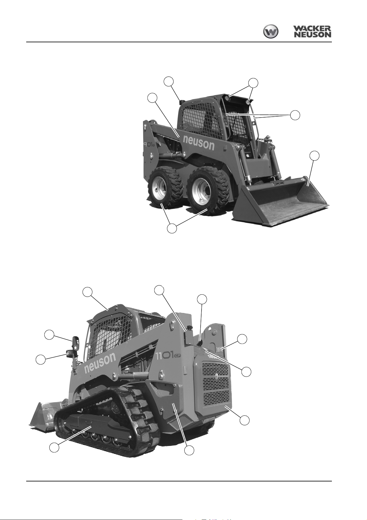
Fig. 1: Machine outside views
1 Front working lights
2 Rear working light (option)
3 Outside rearview mirror (option)
4 Front lights (option)
5 Handholds
6 Standard bucket
7 Loader unit
8 Engine cover
9 Standard tires (model 901)
10 Track drive (model 1101)
11 Numberplate bracket (option)
6
3
7
11
13
1
10
9
2
4
5
12
14
15
16
12 Exhaust pipe
13 Extra weight (option)
14 Crane-lifting bracket (option)
15 Type label
16 Maintenance flap
8
1.2 Machine overview
1-2 BA 901/1101 en – Edition 2.1 * 91101b110.fm
Page 13

1.3 Brief description
Notice!
Introduction
The model 901 and 1101 compact loaders are self-propelled work machines.
Get informed on and follow the legal regulations of your country.
This machine is a versatile and powerful helper for moving earth, gravel and debris on construction sites and elsewhere. A wide range of attachments accounts for the numerous
applications of the machine. See chapter 1.4 Fields of application, attachments for further
applications.
The main components of the machine are:
• ROPS tested cabin
• FOPS 1 tested cabin
• FOPS 2 tested cabin (option)
• Models 901s and 1101c: water-cooled turbocharged Deutz diesel engine
• Model 901sp is available as an option with features differing from model 901s as
follows:
• Powerflow hydraulic system with increased oil flow
• Model 1101cp is available as an option with features differing from model 1101c as
follows:
• Powerflow hydraulic system with increased oil flow
• Sturdy steel sheet chassis, rubber-mounted engine
• Axial piston motor with reduction gear
• Hydraulic parking brake
Traveling drive
Operating hydraulics
Cooling system
The machine can be equipped with the “Telematic” option (for transmitting oper-
ating data, location, etc. via satellite).
The diesel engine permanently drives two axial-piston variable displacement pumps
whose oil flow is sent to the axial piston motors on the left and right.
The diesel engine also drives the joint gear pump for the operating hydraulics. The oil flow
of this pump depends on the diesel engine speed only.
The indicator lights on the instrument panel of the machine ensure constant monitoring of
the engine and hydraulic oil temperature, as well as of the coolant temperature and level.
BA 901/1101 en – Edition 2.1 * 91101b110.fm 1-3
Page 14

Introduction
Caution!
Cabin (ROPS and FOPS)
Modifying or performing improper repair work on the cabin is dangerous. Do
not modify the cabin. Repair work may only be performed by a Wacker Neuson
service center. If the cabin has been damaged, check it before resuming work
and have it repaired if necessary. Please contact your Neuson dealer for
support. Failure to follow this precautionary measure can lead to serious or
fatal injury. The cabin has been specially designed for your protection in case
of an accident.
Fasten your seatbelt, otherwise you can be thrown around or even outside the
cabin and crushed. Therefore always fasten your seat belt as you perform
machine travel and operation. Tighten the seat belt before starting machine
operation.
1-4 BA 901/1101 en – Edition 2.1 * 91101b110.fm
Page 15

1.4 Fields of application, attachments
Caution!
The attachments will decide in the first place how the loader is used.
In order to avoid damage to the machine, only the attachments listed below
have been certified for installation on the machine.
☞ Please contact your Neuson dealer if you wish to use other attachments.
Using tools of other manufacturers, or tools which have been released for other loader
types, can reduce the machine’s output and stability considerably, and can also cause
damage to the machine and injuries to the operator or the personnel.
The buckets listed below have been released by Neuson and are certified for transport on
public roads. However, the national provisions of the country shall apply in which the
machine is used.
Attachments which have been subsequently released for your machine may possibly not
be certified for transport on public roads. This requires a separate certification from the
competent authority.
Always compare the weight of the attachment and its maximum payload with the indications in the lift capacity table. Never exceed the maximum payload.
Introduction
BA 901/1101 en – Edition 2.1 * 91101b110.fm 1-5
Page 16

Introduction
Use: attachment Possible attachments
Description of attachment
Standard bucket
Excavation bucket
Multipurpose bucket
Lightweight material bucket
“4-in-1” bucket
“4-in-1” bucket with teeth
Weight Capacity Loader
219 kg
230 kg
234 kg
246 kg
357 kg
357 kg
382 kg
382 kg
475 kg
475 kg
475 kg
475 kg
0.46 m
0.49 m
0.46 m
0.49 m
0.73 m
0.73 m
3
1 m
3
1 m
0.54 m
0.54 m
0.54 m
0.54 m
3
901
3
1101
3
901
3
1101
3
901
3
1101
901
1101
3
901
3
1101
3
901
3
1101
Remarks
Loosening, picking up, transporting and loading loose or solid
material (material density p = 2 t/m³)
Good excavation and tearout features
Bucket for picking up large-volume material
For picking up and transporting low-density material such as
refuse or sawdust
Multipurpose bucket used for a wide range of applications as
a bucket, grader or grab, or for filling in material.
Multipurpose bucket used for a wide range of applications as
a bucket, grader or grab, or for filling in material. Excavation
work performed more easily with teeth.
Rotary broom
Multipurpose bucket
Agricultural grab
Pallet forks
Hydraulic hammer kit NE 36
Hydraulic hammer NE 36
389 kg
389 kg
383 kg
383 kg
292 kg
292 kg
179 kg
179 kg
193 kg
350 kg
--
For cleaning streets, yards and sidewalks
1101
901
--
901
1101
For heavy industrial applications in foundries, recycling
plants, metal and paper recycling
901
--
For agricultural and industrial applications
1101
901
--
For transporting material on pallets
1101
-- 901/1101 Hydraulic hammer console
-- 901/1101 Hydraulic hammer
1-6 BA 901/1101 en – Edition 2.1 * 91101b110.fm
Page 17

1.5 Regulations
Introduction
Requirements to be met by the operator
Earth moving machines may be driven and serviced only by persons who meet the following requirements:
• 18 years or older
• Physically and mentally suited for this work
• Persons have been instructed in driving and servicing the earth moving machine and
have proven their qualifications to the contractor
• Persons are expected to perform work reliably.
They have been appointed by the contractor for driving and servicing the earth moving
machine.
Get informed on and follow the legal regulations of your country.
BA 901/1101 en – Edition 2.1 * 91101b110.fm 1-7
Page 18

Introduction
EC Declaration of Conformity
According to Machine Directive 2006/42/EC, appendix II A
Manufacturer
Wacker Neuson Linz GmbH
Haidfeldstr. 37
4060 Linz-Leonding
Product
Machine designation: Compact loader
Machine model: 901s
Serial no.: ______________
Output (kW): 50 kW
Measured sound power level: 101.3 dB (A)
Guaranteed sound power level: 101 dB (A)
Conformity assessment procedure
Notified body according to Directive 2006/42/EC, appendix XI:
Fachausschüsse Bau und Tiefbau
Prüf- und Zertifizierungsstelle im BG-PRÜFZERT
Landsberger Str. 309
D-80687 Munich
Distinguishing EU number 0036
Notified body according to Directive 2000/14/EC, appendix VI:
TÜV SÜD Industrie Service GmbH
Westendstr. 199
D-80686 Munich
Directives and standards
We hereby declare that this product corresponds to the relevant regulations and requirements of the following Directives and
standards:
2006/42/EC (old 98/37 EC), 2004/108/EC (old 89/336/EEC), 2002/44/EC, 2005/88/EC, 2000/14/EC;
DIN EN ISO 12100-1 and 2, DIN EN 474-1 and 3, DIN EN 14121,
DIN EN 3471, DIN EN 13510, EN ISO 3744, EN ISO 3746, DIN EN ISO 3449
Josef Erlinger,
Managing director
Thomas Köck,
Responsible for documentation
Leonding,
Place, date
Declaration of conformity 901s
1-8 BA 901/1101 en – Edition 2.1 * 91101b110.fm
Page 19
Declaration of conformity 901sp
EC Declaration of Conformity
According to Machine Directive 2006/42/EC, appendix II A
Manufacturer
Wacker Neuson Linz GmbH
Haidfeldstr. 37
4060 Linz-Leonding
Product
Machine designation: Compact loader
Machine model: 901sp
Serial no.: ______________
Output (kW): 63 kW
Measured sound power level: 100.5 dB (A)
Guaranteed sound power level: 101 dB (A)
Conformity assessment procedure
Notified body according to Directive 2006/42/EC, appendix XI:
Fachausschüsse Bau und Tiefbau
Prüf- und Zertifizierungsstelle im BG-PRÜFZERT
Landsberger Str. 309
D-80687 Munich
Distinguishing EU number 0036
Notified body according to Directive 2000/14/EC, appendix VI:
TÜV SÜD Industrie Service GmbH
Westendstr. 199
D-80686 Munich
Directives and standards
We hereby declare that this product corresponds to the relevant regulations and requirements of the following Directives and
standards:
2006/42/EC (old 98/37 EC), 2004/108/EC (old 89/336/EEC), 2002/44/EC, 2005/88/EC, 2000/14/EC;
DIN EN ISO 12100-1 and 2, DIN EN 474-1 and 3, DIN EN 14121,
DIN EN 3471, DIN EN 13510, EN ISO 3744, EN ISO 3746, DIN EN ISO 3449
Josef Erlinger,
Managing director
Thomas Köck,
Responsible for documentation
Leonding,
Place, date
Introduction
BA 901/1101 en – Edition 2.1 * 91101b110.fm 1-9
Page 20
Introduction
EC Declaration of Conformity
According to Machine Directive 2006/42/EC, appendix II A
Manufacturer
Wacker Neuson Linz GmbH
Haidfeldstr. 37
4060 Linz-Leonding
Product
Machine designation: Compact loader
Machine model: 1101c
Serial no.: ______________
Output (kW): 63 kW
Measured sound power level: 103.9 dB (A)
Guaranteed sound power level: 104 dB (A)
Conformity assessment procedure
Notified body according to Directive 2006/42/EC, appendix XI:
Fachausschüsse Bau und Tiefbau
Prüf- und Zertifizierungsstelle im BG-PRÜFZERT
Landsberger Str. 309
D-80687 Munich
Distinguishing EU number 0036
Notified body according to Directive 2000/14/EC, appendix VI:
TÜV SÜD Industrie Service GmbH
Westendstr. 199
D-80686 Munich
Directives and standards
We hereby declare that this product corresponds to the relevant regulations and requirements of the following Directives and
standards:
2006/42/EC (old 98/37 EC), 2004/108/EC (old 89/336/EEC), 2002/44/EC, 2005/88/EC, 2000/14/EC;
DIN EN ISO 12100-1 and 2, DIN EN 474-1 and 3, DIN EN 14121,
DIN EN 3471, DIN EN 13510, EN ISO 3744, EN ISO 3746, DIN EN ISO 3449
Josef Erlinger,
Managing director
Thomas Köck,
Responsible for documentation
Leonding,
Place, date
Declaration of conformity 1101c
1-10 BA 901/1101 en – Edition 2.1 * 91101b110.fm
Page 21

Declaration of conformity 1101cp
EC Declaration of Conformity
According to Machine Directive 2006/42/EC, appendix II A
Manufacturer
Wacker Neuson Linz GmbH
Haidfeldstr. 37
4060 Linz-Leonding
Product
Machine designation: Compact loader
Machine model: 1101cp
Serial no.: ______________
Output (kW): 63 kW
Measured sound power level: 103.9 dB (A)
Guaranteed sound power level: 104 dB (A)
Conformity assessment procedure
Notified body according to Directive 2006/42/EC, appendix XI:
Fachausschüsse Bau und Tiefbau
Prüf- und Zertifizierungsstelle im BG-PRÜFZERT
Landsberger Str. 309
D-80687 Munich
Distinguishing EU number 0036
Notified body according to Directive 2000/14/EC, appendix VI:
TÜV SÜD Industrie Service GmbH
Westendstr. 199
D-80686 Munich
Directives and standards
We hereby declare that this product corresponds to the relevant regulations and requirements of the following Directives and
standards:
2006/42/EC (old 98/37 EC), 2004/108/EC (old 89/336/EEC), 2002/44/EC, 2005/88/EC, 2000/14/EC;
DIN EN ISO 12100-1 and 2, DIN EN 474-1 and 3, DIN EN 14121,
DIN EN 3471, DIN EN 13510, EN ISO 3744, EN ISO 3746, DIN EN ISO 3449
Josef Erlinger,
Managing director
Thomas Köck,
Responsible for documentation
Leonding,
Place, date
Introduction
BA 901/1101 en – Edition 2.1 * 91101b110.fm 1-11
Page 22
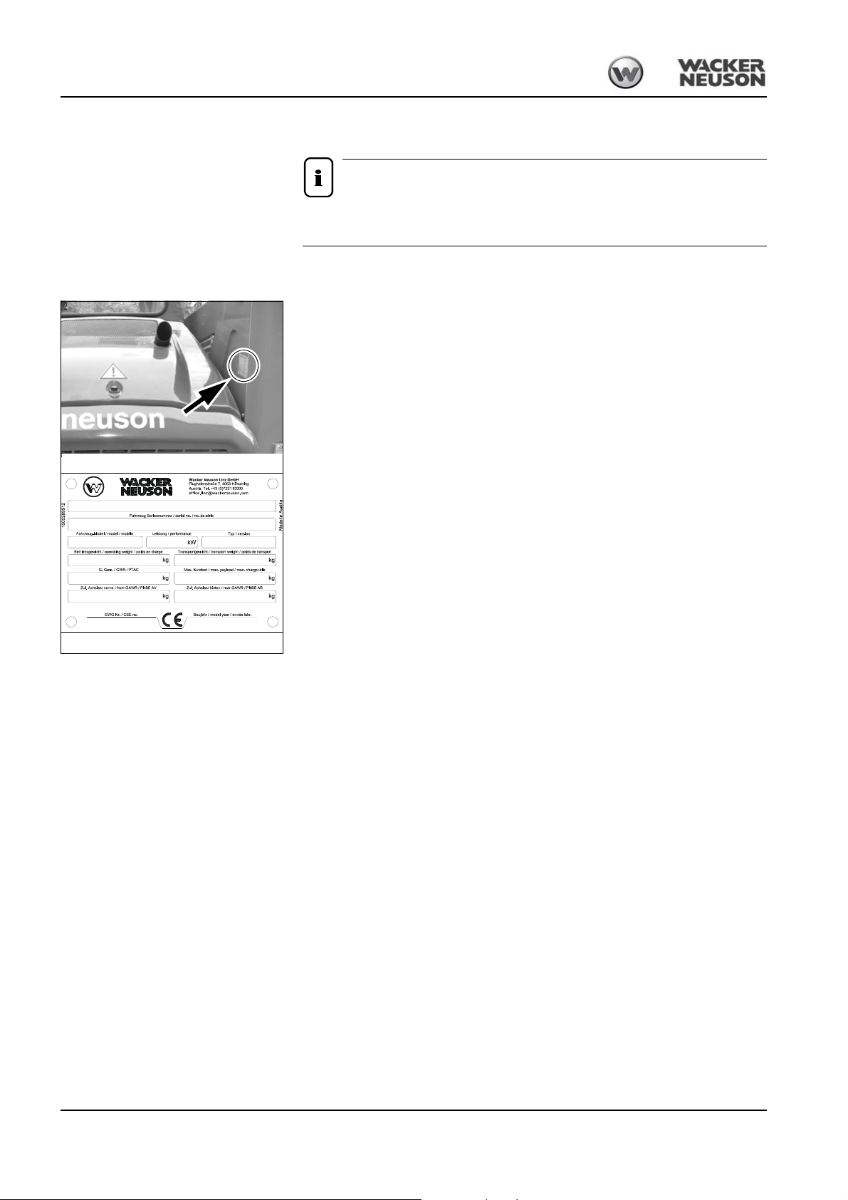
Introduction
Notice!
Fig. 1: Type label: location
Fig. 2: Type label (symbolic representation)
1.6 Type labels and component numbers
Type, quantity and position of the labels depend on options, country and
machine.
Serial number
The serial number is stamped on the machine chassis. It is located at the front left on the
chassis and on the type label.
The type label is located at the rear right or left on the chassis.
Type label information
Machine model 1101cp
Model year: 2007
Chassis no.: AD 000000
Machines with two asterisks before and after the serial number are equipped with hinged
maintenance flaps.
Output: 63 kW
Dead weight: 4400 kg
Max. payload: 1150 kg
AD 000000**
Other information – see chapter 6 Technical data on page 6-1
1-12 BA 901/1101 en – Edition 2.1 * 91101b110.fm
Page 23

7/8-digit serial number (up to 2012)
Notice!
Notice!
123
AD 51001 D
Fig. 3:
12345 6
WNC E 1301 A PAL 00400
A
S
D
Fig. 4:
Fig. 5: Diesel engine number
Introduction
Position
1 Machine version
2 Serial number
3 Equipment feature (optional)
Wacker Neuson track dumpers still have 7/8-digit serial numbers, even after 2012.
17-digit serial number (from 2012)
For easier machine identification, Wacker Neuson introduced a 17-digit serial number for
compact equipment in 2012 (for example for excavators). This serial number includes
additional data, for example the manufacturer code and the production site.
Position
1 Manufacturer code
2 Machine model
A
S
D
E
3 Internal model designation
4 Check letter
5 Production site
Unit
Compact loaders
Dumper
Excavator
Description
Description
6 Serial number
Wacker Neuson components (for example Easy Lock, tilt bucket, rollbar) have
numeric serial numbers only.
Engine number
The type label (arrow) is located on the cylinder-head cover (engine).
BA 901/1101 en – Edition 2.1 * 91101b110.fm 1-13
Page 24

Introduction
Fig. 6: CE mark
ce.ai
Meaning
The CE mark means that the machine meets the requirements of the Machine Directive
and that the conformity procedure has been performed. The machine meets all the health
and safety requirements of the Machine Directive.
Location
On the type label
1-14 BA 901/1101 en – Edition 2.1 * 91101b110.fm
Page 25
1.7 Signs and symbols
Fig. 7: Danger label
Fig. 8: Operator’s manual
Fig. 9: Swiveling range
Fig. 10: Loader unit prop
Warning and safety labels
The following states signs and symbols which are not unequivocally comprehensible. They
do not contain explanatory text and are not explained in the following chapters.
Meaning
General indication of danger
Location
On the boom on the left and right.
Meaning
Carefully read the Operator’s Manual and familiarize yourself with the machine before putting it into operation
Location
Inside the cabin (seat console)
Introduction
Meaning
Stay clear of the machine’s slewing range during operation.
Location
Upper edge of radiator
Meaning
The danger zone may be accessed only if the prop is installed.
Location
1 x cabin prop
1 x loader unit prop
BA 901/1101 en – Edition 2.1 * 91101b110.fm 1-15
Page 26
Introduction
Fig. 11: Loader unit working range
Fig. 12: Caution: high-pressure fluid
Fig. 13: Pressure accumulator
Fig. 14: Crushing hazard
Meaning
Stay clear of the working range of the loader unit.
Location
2 x on the loader unit on the left and right.
Meaning
Caution: high-pressure fluids can escape
Location
1 x on the radiator on the right
Meaning
Receptacle (pressure accumulator, radiator ...) under pressure (gas, oil)
Location
1 x on the radiator on the right
1 x in pump area on the right (accumulator)
Meaning
Always stay clear of the area with crushing hazard while parts in this area can move.
Location
2 x on the loader unit cylinder on the left and right
2 x on the quickhitch system
2 x inside the cabin
1-16 BA 901/1101 en – Edition 2.1 * 91101b110.fm
Page 27
Meaning
Fig. 15: V-belts
Fig. 16: Engine cover
Fig. 17: Hot surface
Fig. 18: Seat belt – slopes
Touch machine parts only after they have come to a full standstill.
Location
1 x radiator
Meaning
Touch machine parts only after they have come to a full standstill.
Location
1 x radiator
Introduction
Meaning
Keep a safe distance from hot surfaces.
Location
1 x radiator
1 x chassis
Meaning
Avoids slopes on which the machine can tip over.
Location
1 x inside the cabin
BA 901/1101 en – Edition 2.1 * 91101b110.fm 1-17
Page 28

Introduction
Fig. 19: No passengers
Fig. 20: Disconnecting the battery
Fig. 21: Guard
Fig. 22: Seat belt
Meaning
Do not use the loader unit for raising persons.
Location
1 x on the loader unit on the left and right
Meaning
Disconnect the battery master switch before performing repair, maintenance and cleaning work.
Location
1 x cabin (seat console)
Meaning
Never open the guards if the engine is still running.
Location
1 x on the engine cover
Meaning
Always keep arms, feet and legs inside the cabin. Always fasten the seat belt during operation.
Location
Inside the cabin (seat console)
1-18 BA 901/1101 en – Edition 2.1 * 91101b110.fm
Page 29
Introduction
Fig. 23: Reservoir under pressure
Fig. 24: Road travel lock
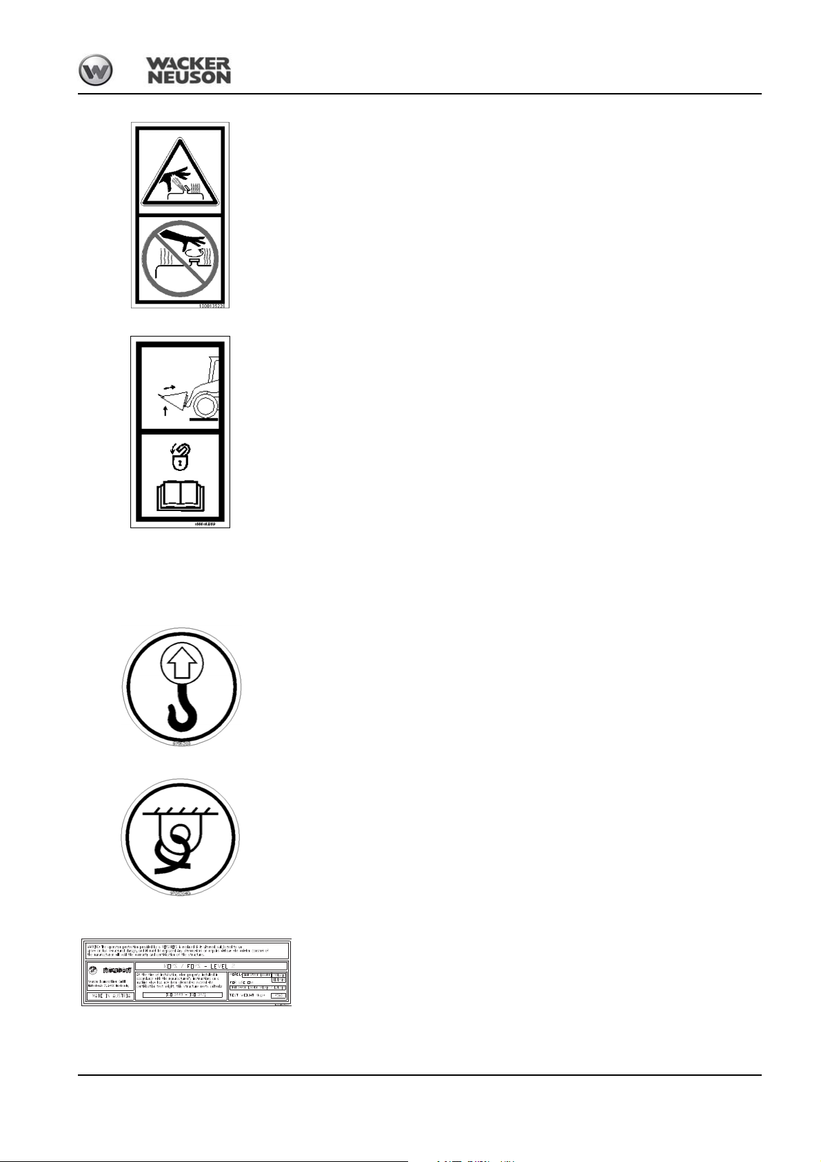
Fig. 25: Eye hook label
Fig. 26: Label for points used for tying down the machine
Fig. 27: ROPS/FOPS
Meaning
Warns of a hot reservoir or container under pressure
Location
On the hydraulic oil reservoir, on the radiator
Meaning
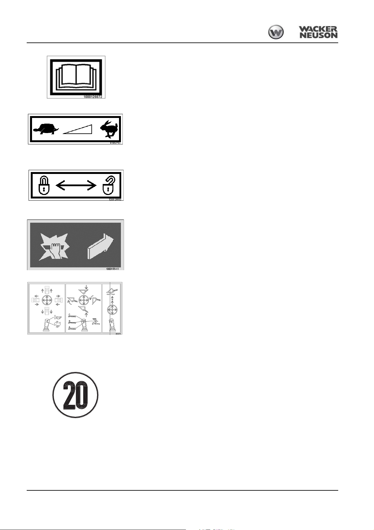
Lock the bucket and the loader unit before performing machine travel on roads.
Location
Cabin (seat console)
Operation and information labels
Meaning
Raise the machine or machine parts only by means of these eyelets!
– see chapter Crane-lifting the machine on page 3-54
Location
At front and rear of cabin
Meaning
Indicates the tie-down points for tying down the machine.
The tie-down points are used for tying down the machine during loading and transportation
– see chapter Tying down the machine on page 3-53.
Location
On the chassis at the front and rear.
Meaning
Cabin complies with ROPS/FOPS level 2
Location
Inside the cabin
BA 901/1101 en – Edition 2.1 * 91101b110.fm 1-19
Page 30
Introduction
Fig. 28: Operator’s Manual
Fig. 29: Describes the throttle lever function
Fig. 30: Quickhitch lock
Fig. 31: Emergency exit
Fig. 32: Joystick assignment (option)
Fig. 33: Design-specific speed
9705059
Meaning
Always read the Operator’s Manual before starting the machine
Location
Cabin roof lining
Meaning
Describes the throttle lever function.
– see chapter If the engine stalls or if it is stopped, only start the engine again after 6 sec-
onds. on page 3-13
Location
Below the throttle lever
Meaning
Describes the quickhitch lock
Location
On quickhitch
Model 901:
Meaning
Describes how to remove the window from the machine.
Location
Inside the cabin on the rear window
Meaning
Describes the ISO control functions
Location
Inside the cabin
Meaning
States design-specific speed.
Location
On either side of the machine
1-20 BA 901/1101 en – Edition 2.1 * 91101b110.fm
Page 31

Options:
Fig. 34: Noise level label
102
101
Model 901s
Model 901sp
104
Model
1101c,
model
1101cp
Fig. 35: Speed Control actuation (option)
1000168722
Blinker-STOP
STOP
C
(OPTIONAL)
(OPTIONAL)
B
(OPTIONAL)
A
(OPTIONAL)
(OPTIONAL)
(OPTIONAL)
(OPTIONAL)
Fig. 36: H controls (option)
Fig. 37: Work lock (H controls option)
Meaning
Noise levels produced by the machine.
L
= sound power level
WA
Other information – see chapter 6.11 Noise levels on page 6-6
Location
On the cabin
Meaning
Actuation of pressure reducing valve
Location
Inside the cabin on the pressure reducing valve wheel
Introduction
Meaning
Describes the function of the H controls (option)
Location
Inside the cabin
Meaning
Describes the function of the H controls work lock option
Location
Inside the cabin next to the work lock changeover valve
BA 901/1101 en – Edition 2.1 * 91101b110.fm 1-21
Page 32

Introduction
Fig. 38: Environmentally hazardous substances
Fig. 39: Easily flammable fluids
Meaning
901: from serial number WNCS0301HPAL00177
1101: from serial number WNCS0302TPAL00189
Environmentally hazardous substances
The tank and fuel lines contain diesel fuel according to the ADR guidelines (European
Agreement concerning the International Carriage of Dangerous Goods by Road).
Location
901: above the rear wheel on the left on the chassis (in travel direction).
1101: at the front left of the chassis (in travel direction).
Meaning
901: from serial number WNCS0301HPAL00177
1101: from serial number WNCS0302TPAL00189
Easily flammable fluids
The tank and fuel lines contain diesel fuel according to the ADR guidelines (European
Agreement concerning the International Carriage of Dangerous Goods by Road).
Location
901: above the rear wheel on the left on the chassis (in travel direction).
1101: at the front left of the chassis (in travel direction).
1-22 BA 901/1101 en – Edition 2.1 * 91101b110.fm
Page 33

1.8 Fire extinguisher
Notice!
Danger!
Fig. 40: Position of fire extinguisher
70 mm
Fig. 41: Ear protection
The fire extinguisher is neither included in the machine’s standard equipment nor is it
available as an option from Wacker Neuson.
☞ Retrofitting a fire extinguisher according to DIN-EN 3 must be performed by an author-
ized service center
☞ Location:
➥ Inside the cabin (see figure)
1.9 Duty to wear ear protectors
Introduction
Check the fire extinguisher at regular intervals, also ensure that it is safely
installed.
Always wear ear protectors during machine travel and operation over a longer
period of time. Failure to do so can cause serious ear damage.
Hearing damage hazard!
☞ Always wear suitable ear protectors during machine travel and operation
Always wear ear protectors due to the increased noise emissions during machine travel
and operation. Store the ear protectors within reach in the cabin.
BA 901/1101 en – Edition 2.1 * 91101b110.fm 1-23
Page 34

Introduction
1-24 BA 901/1101 en – Edition 2.1 * 91101b110.fm
Page 35

2 Safety instructions
Danger!
Caution!
Notice!
Environment!
2.1 Identification of warnings and dangers
Important indications regarding the safety of the personnel and the machine are identified
in this Operator’s Manual with the following terms and symbols:
Failure to observe the instructions identified by this symbol can cause injury or
death for the operator or other persons.
☞ Measures for avoiding danger
Failure to observe the instructions identified by this symbol can cause damage
to the machine.
☞ Measures for avoiding danger for the machine
Safety instructions
2.2 Warranty
This symbol identifies instructions for a more efficient and economical use of the
machine.
Failure to observe the instructions identified by this symbol can cause damage to the environment. The environment is in danger if environmentally hazardous material (waste oil,
for example) is not subject to proper use or disposal.
Warranty claims can be brought forward to your Neuson dealer only.
Furthermore, the instructions in this Operator’s Manual must be observed.
BA 901/1101 en – Edition 2.1 * 91101b210.fm 2-1
Page 36

Safety instructions
2.3 Designated use and exemption from liability
• The machine is intended for:
• moving earth, gravel, coarse gravel or ballast and rubble as well as for
• working with the attachments indicated in chapter Fields of application
• Every other application is regarded as not designated for the use of the machine.
Neuson will not be liable for damage resulting from use other than mentioned above.
The user alone will bear the risk.
Designated use also includes observing the instructions set forth in the Operator’s
Manual and observing the maintenance and service conditions.
• The safety of the machine can be negatively affected by performing machine modifications without proper authority and by using spare parts, equipment, attachments and
optional equipment that have not been checked and released by Neuson. Neuson will
not be liable for damage resulting from this
• Neuson Baumaschinen GmbH shall not be liable for injury and/or damage to property
caused by failure to observe the safety instructions and the Operator’s Manual, and by
the negligence of the duty to exercise due care when:
• handling
• operating
• servicing and performing maintenance and
• repairing the machine. This is also applicable in those cases in which special
attention has not been drawn to the duty to exercise due care, in the safety instructions, the Operator’s Manuals and maintenance manuals (machine/engine).
• Read and understand the Operator’s Manual before starting up, servicing or repairing
the machine. Observe the safety instructions!
• The machine may not be used for transport jobs on public roads
2-2 BA 901/1101 en – Edition 2.1 * 91101b210.fm
Page 37

2.4 General conduct and safety instructions
Organizational measures
• The machine has been designed and built in accordance with state-of-the-art standards
and the recognized safety regulations. Nevertheless, its use can carry a risk to life and
limb of the user or of third parties, or cause damage to the machine and to other
material property
• The machine must only be used in technically perfect condition in accordance with its
designated use and the instructions set forth in the Operator’s Manual, and only by
safety-conscious persons who are fully aware of the risks involved in operating the
machine! Any malfunctions, especially those affecting safety, must therefore be
rectified immediately!
Basic rule:
Before putting the machine into operation, inspect the machine for safety in work and
road operation!
• Careful and prudent working is the best way to avoid accidents!
• The Operator’s Manual must always be at hand at the place of use of the machine, and
must therefore be kept in the storage compartment provided for in the cabin.
Immediately complete or replace an incomplete or illegible Operator’s Manual
Safety instructions
• In addition to the Operator’s Manual, observe and instruct the operator in all other
generally applicable legal and other mandatory regulations relevant to accident
prevention and environmental protection.
These compulsory regulations may also deal with handling hazardous substances,
issuing and/or wearing personal protective equipment, or traffic regulations
• With regard to specific operational features, for example those relevant to job organization, work sequences or the persons entrusted with the work, supplement the
Operator’s Manual by corresponding instructions, including those relevant to supervising and reporting duties
• Persons entrusted with work on the machine must have read and understood the
Operator’s Manual and in particular, chapter “Safety Instructions” before beginning
work. This applies especially to persons working only occasionally on the machine, for
example set-up or maintenance
• The user/owner must check – at least from time to time – whether the persons
entrusted with operation or maintenance are working in compliance with the Operator’s
Manual and are aware of risks and safety factors
• The user/owner commits himself to operate and keep the machine in perfect condition,
and, if necessary or required by law, to require the operating or servicing persons to
wear protective clothing, etc.
• In the event of safety-relevant modifications or changes on the machine or of its
behavior, stop the machine immediately and report the malfunction to the competent
authority/person.
Safety-relevant damage or malfunctions of the machine must be rectified immediately
• Never make any modifications, additions or conversions to the machine and its superstructures (for example the cabin, etc.), as well as to the attachments, which might
affect safety without the approval of Neuson! This also applies to the installation and
the adjustment of safety devices and valves, as well as to welding work on load-bearing
elements
• Spare parts must comply with the technical requirements specified by Neuson. Original
spare parts can be relied to do so
• Replace hydraulic hoses within stipulated and appropriate intervals even if no safetyrelevant malfunctions have been detected.
BA 901/1101 en – Edition 2.1 * 91101b210.fm 2-3
Page 38

Safety instructions
1000168730
Fig. 42: Protective equipment
• Before working on or with the machine, remove jewelry, such as rings, wristwatches,
bracelets, etc., and tie back long hair and do not wear loose-fitting garments, such as
unbuttoned or unzipped jackets, ties or scarves.
Injury can result from being caught up in the machinery or from rings catching on
moving parts!
• Wear a hard hat, protective goggles, protective gloves and other protective equipment
during maintenance or as required by a specific situation.
• Always wear ear protectors during machine travel and operation over a longer period of
time. Failure to do so can cause serious ear damage.
• Keep the machine clean. This reduces
• Fire hazard, for example due to oil-soaked rags lying around
• Injury hazard, for example due to dirt or debris on the footholds, and
• Accident hazard for example due to dirt pile-up on the accelerator pedals
• Observe all safety, warning and information signs and labels on the machine
• Adhere to prescribed intervals or those specified in the Operator’s Manual for routine
checks/inspections and maintenance!
• For service, inspection, maintenance or repair work, tools and service center
equipment adapted to the task on hand are absolutely indispensable
Selection and qualification of personnel, basic responsibilities
• Any work on or with the machine must be performed by reliable personnel only. Do not
let unauthorized persons perform machine travel or operation! Observe statutory
minimum age limits!
• Employ only trained or instructed personnel on the machine, and clearly and unequivocally define the individual responsibilities of the personnel for operation, set-up, maintenance and repair!
• Define the machine operator’s responsibilities – also with regard to observing traffic
regulations. Give the operator the authority to refuse instructions by third parties that
are contrary to safety
• Do not allow persons to be trained or instructed or persons taking part in a general
training course to work on or with the machine without being permanently supervised
by an experienced person!
• Work on the electrical system and equipment, on the travel gear and the steering and
braking systems may only be performed by technical personnel that has been specially
trained for such work.
Work on the hydraulic system of the machine must be performed only by personnel
with special knowledge and experience in hydraulic systems!
• Seal off the danger zone should it not be possible to keep a safe distance.
Stop machine operation if persons do not leave the danger zone in spite of warning!
Keep out of the danger zone!
Danger zone:
The danger zone is the area in which persons are in danger due to the movements of the
• machine
• work equipment
• additional equipment or
• material
• This also includes the area affected by falling material, equipment or by debris that is
thrown out.
The danger zone must be extended by 0.5 m in the immediate vicinity of
• buildings
• scaffolds or
• other elements of construction
2-4 BA 901/1101 en – Edition 2.1 * 91101b210.fm
Page 39

2.5 Safety instructions regarding operation
Normal operation
• Avoid any operational mode that might be prejudicial to safety!
• Before beginning work, familiarize yourself with the surroundings and circumstances of
the job site. These are, for example, obstacles in the working and traveling area, the soil
bearing capacity and any necessary barriers separating the job site from public roads
• Take the necessary precautions to ensure that the machine is used only when in a safe
and reliable state!
Operate the machine only if all protective and safety-oriented devices, for example
removable safety devices, soundproofing elements and mufflers, etc., are in place and
fully functional!
• Check the machine at least once a day/per work shift for visible damage and malfunctions! Report any changes (incl. changes in working behavior) to the competent organization/person immediately! If necessary, stop the machine immediately and lock it!
• In the event of malfunctions, stop the machine immediately and lock it! Have any
malfunctions rectified immediately!
Safety instructions
• Start and operate the machine only from the operator seat!
• Perform start-up and shut-down procedures in accordance with the Operator’s Manual,
and observe the indicator lights!
• Before putting the machine/attachment into operation (start-up/moving), ensure that no
one is at risk by putting the machine/attachment into operation!
• Before performing machine travel, and also after interrupting work, check whether the
drive pedals, the signaling and the light systems are functional!
• Before starting machine travel always check whether the supplementary equipment
and the attachments have been safely stowed away or attached!
• During machine travel on public roads, ways and places, observe the valid traffic
regulations and, if necessary, ensure beforehand that the machine is in a condition
perfectly compatible with these regulations!
• Always switch on the lights in conditions of poor visibility and after dark!
• No lifting, lowering or carrying persons in the work equipment/attachments!
• Installing a man basket or a working platform is prohibited!
• When crossing underpasses, bridges and tunnels, or when passing under overhead
lines always ensure that there is enough clearance!
• Always keep a safe distance from the edges of building pits and slopes!
• When working in buildings or in enclosed areas, look out for:
• Height of the ceiling/clearances
• Width of entrances
• Maximum load of ceilings and floors
• Sufficient room ventilation – poisoning hazard!
BA 901/1101 en – Edition 2.1 * 91101b210.fm 2-5
Page 40

Safety instructions
• Avoid any operation that might be a risk to machine stability!
• During operation on slopes, perform machine travel or operation uphill or downhill. If
performing machine travel across a slope cannot be avoided, bear in mind the tilting limit of
the machine!
Always keep the attachments/work equipment close to the ground. This also applies to
downhill machine travel!
During machine travel across a slope, the load must be on the uphill side of the machine.
• On sloping terrain always adapt the travel speed to the prevailing ground conditions!
Never change to lower gear on a slope but always before reaching it!
• Before leaving the operator seat always secure the machine against unintentional
movement and unauthorized use!
Lower the work equipment/attachments to the ground
• Before starting work check whether
• all safety devices are properly installed and functional
• Before starting machine travel or before taking up work:
• Ensure that visibility is sufficient (do not forget rearview mirrors!)
• Adjust your correct seat position, never adjust the operator seat during machine
travel or operation!
• Fasten your seat belt
• Inspect the immediate area (children!)
• On the job site the operator is responsible for third parties!
• Caution when handling fuel – increased fire hazard!
• Ensure that fuel does not come into contact with hot parts!
Do not smoke during refueling, and avoid fire and sparks. Stop the engine during
refueling and do not smoke!
• Never get on or off a moving machine! Never jump off the machine!
• Should the lights of the machine not be sufficient for performing work safely, provide
additional lighting of the job site
• Installed work lights must not be switched on for travel on public roads. They can be
switched on in work operation if motorists are not blinded
• The accelerator pedals take time getting used to them. Therefore, adjust the travel
speed to your abilities and the circumstances.
Applications with lifting gear
Definition:
Applications with lifting gear are understood as procedures involving raising, transporting
and lowering loads with the help of slings and load-securing devices (for example ropes,
chains). In doing so, the help of persons is necessary for securing and detaching the load.
This applies, for example, to lifting and lowering pipes, shaft rings or containers.
• No applications with lifting gear!
2-6 BA 901/1101 en – Edition 2.1 * 91101b210.fm
Page 41

Trailers and attachments
Safety instructions
• No trailer operation!
• Prior to machine travel on public roads, remove all attachments that cannot be secured
in compliance with the legal regulations of your country!
• Attachments and counterweights affect handling and the machine’s steering capability!
• Fit the attachments with the specially required devices only!
• Before uncoupling or coupling hydraulic lines (hydraulic quick couplers)
• Stop the engine
• Release the pressure in the hydraulic system. In order to do so, move the control
levers of the hydraulic control units back and forth a couple of times
• Coupling attachments requires special care!
• Secure the attachments against unintentional movement!
• Operate the machine only if all protective facilities have been installed and are
functional, and if all brake, light and hydraulic connections have been connected!
• If optional equipment is installed, all lighting equipment, indicator lights, etc. that are
required in addition must be installed and functional
• Install attachments only if the drive is switched off
• Especially during machine travel and operation with machines equipped with a quickhitch for the attachments, ensure that the attachment is securely locked in the quickhitch. The lock pin must be visible on either side of the bores on the attachment. Check
before starting work
• Prior to fitting attachments to the loader unit, secure the control lever of the hydraulic
control unit against unintentional movement
Transportation
• The machine must be towed, loaded and transported only in accordance with the
Operator’s Manual!
• For towing the machine observe the prescribed transport position, permissible speed
and itinerary
• Use only suitable means of transport of adequate capacity/payload!
• Safely secure the machine on means of transport! Use suitable tie-down points and
load-securing devices
• The recommissioning procedure must be strictly in accordance with the Operator’s
Manual!
BA 901/1101 en – Edition 2.1 * 91101b210.fm 2-7
Page 42

Safety instructions
2.6 Safety instructions for maintenance
• Avoid any operational mode that might be prejudicial to safety!
• Observe the adjustment, maintenance and inspection activities and intervals set forth in
the Operator’s Manual, including information on the replacement of parts/partial
equipment!
These activities must be performed by technical personnel only.
• The machine may not be serviced, repaired or test-driven by unauthorized personnel
• Brief operating personnel/operator before beginning special operations and maintenance! Appoint a person to supervise the activities!
• In any work concerning the operation, conversion or adjustment of the machine and its
safety-oriented devices, or any work related to maintenance, inspection and repair,
observe the start-up and shut-down procedures set forth in the Operator’s Manual, and
the information on maintenance
• If required, secure the maintenance area appropriately!
• Prior to performing service, maintenance and repair work, attach a warning label, such
as “Repair work – do not start machine!”, to the starter or to the control elements.
Remove the starting key!
• Perform service, maintenance and repair work only if
• the machine is positioned on firm and level ground
• the control lever base is raised
• all hydraulically movable attachments and working equipment have been lowered to
the ground
• the engine is stopped
• the starting key is removed and
• the machine has been secured against unintentional movement
• Should maintenance or repair be inevitable with the engine running:
• Only work in groups of two
• Both persons must be authorized for the operation of the machine
• One person must be seated on the seat and maintain visual contact with the other
person
• Observe the specific safety instructions in the work manual
• Keep a safe distance from all rotating and moving parts, for example fan blades, V-
belt drives, PTO shaft drives, fans, etc.
• Prior to performing assembly work on the machine, ensure that no movable parts will
roll away or start moving
• To avoid accident hazard, parts and large assemblies being moved for replacement
purposes must be carefully attached and secured to lifting gear.
Use only suitable lifting gear and suspension systems in a technically perfect state with
adequate load-bearing capacity!
Stay clear of suspended loads!
2-8 BA 901/1101 en – Edition 2.1 * 91101b210.fm
Page 43

Safety instructions
• Have loads fastened and crane operators guided by experienced persons only!
The person guiding the operator must be within sight or sound of him
• Always use specially designed or otherwise safety-oriented ladders and working
platforms to perform overhead assembly work.
Never use machine parts or attachments/superstructures as a climbing aid!
Wear a safety harness when performing maintenance at greater heights!
Keep all handholds, steps, handrails, platforms, landings and ladders free from dirt,
snow and ice!
• Clean the machine, especially connections and threaded unions, of any traces of oil,
fuel or preservatives before performing maintenance/repair work!
Do not use aggressive detergents!
Use lint-free cleaning rags!
• Before cleaning the machine with water, steam jet (high-pressure cleaner) or detergents, cover or tape up all openings which – for safety and functional reasons – must
be protected against water, steam or detergent penetration. Special care must be taken
with the electrical system
• After cleaning, remove all covers and tapes applied for that purpose!
• After cleaning, examine all fuel, lubricant and hydraulic oil lines for leaks, chafe marks
and damage!
Rectify all malfunctions without delay!
• Always tighten any threaded fittings that have been loosened during maintenance and
repair!
• Any safety devices removed for set-up, maintenance or repair purposes must be
refitted and checked immediately upon completion of the maintenance and repair work
• Ensure that all consumables and replaced parts are disposed of safely and with
minimum environmental impact!
• Do not use the work equipment as lifting platforms for persons!
• Before taking up work on machine parts dangerous for life and limb (bruising, cutting),
always ensure safe blocking/support of these areas
• Perform maintenance and repair work beneath a raised machine, attachments or
additional equipment only if a safe and secure support has been provided for (the sole
use of hydraulic cylinders, jacks, etc. does not sufficiently secure raised machines or
equipment/attachments)
• Avoid contact with hot parts, such as the engine block or the exhaust system during the
operation of the machine and for some time afterward – burn hazard!
• Retainer pins can fly out or splinter when struck with force – injury hazard!
• Do not use starting fuel! This especially applies to those cases in which a heater plug
(intake-air preheating) is used at the same time – explosion hazard!
• Apply special care when working on the fuel system – increased fire hazard!
BA 901/1101 en – Edition 2.1 * 91101b210.fm 2-9
Page 44

Safety instructions
2.7 Warning of special hazards
Electrical energy
• Use only original fuses with the specified current rating!
Switch off the machine immediately and rectify the malfunction if trouble occurs in the
electrical system!
• During machine operation, maintain a safe distance from overhead electric lines! If
work must be performed close to overhead lines, the equipment/attachments must be
kept well away from them. Caution, danger! Get informed on the prescribed safety
distances!
• If your machine comes into contact with a live wire
• Do not leave the machine
• Drive the machine out of the danger zone
• Warn others against approaching and touching the machine
• Have the live wire de-energized
• Do not leave the machine until the line that has been touched or damaged has been
• Work on the electrical system may only be performed by a technician with appropriate
training, in accordance with the applicable electrical engineering rules
• Inspect and check the electric equipment of the machine at regular intervals. Malfunctions such as loose connections or scorched cables must be rectified immediately
• Observe the operating voltage of the machine/attachments!
• Always remove the grounding strap from the battery when working on the electrical
system or when performing welding work!
• Starting with battery jumper cables can be hazardous if performed improperly. Observe
the safety instructions regarding the battery!
Gas, dust, steam, smoke
safely de-energized!
Hydraulic system
• Operate the machine only on adequately ventilated premises! Before starting internal
combustion engines or operating fuel-operated heating systems on enclosed premises,
ensure that there is sufficient ventilation!
Observe the regulations in force at the respective site!
• Perform welding, flame-cutting and grinding work on the machine only if this has been
expressly authorized. There can be an explosion and fire hazard, for example!
• Before performing welding, flame-cutting and grinding work, clean the machine and its
surroundings from dust and other inflammable substances, and ensure that the
premises are adequately ventilated – explosion hazard!
• Work on the hydraulic equipment of the machine must be performed only by persons
having specific technical knowledge and experience in hydraulic systems!
• Check all lines, hoses and threaded fittings regularly for leaks and obvious damage!
Repair any damage and leaks immediately! Splashed oil can cause injury and fire
• In accordance with the Operator’s Manual/instructions for the respective assembly,
release the pressure in all system sections and pressure lines (hydraulic system) to be
opened before performing any implementing/repair work!
• Hydraulic and compressed-air lines must be laid and fitted properly. Ensure that no
connections are interchanged. The fittings, lengths and quality of the hoses must
comply with the technical requirements
2-10 BA 901/1101 en – Edition 2.1 * 91101b210.fm
Page 45

Noise
Oil, grease and other chemical substances
Battery
Tires (model 901)
Safety instructions
• During operation all sound baffles must be closed
• Wear ear protectors if necessary!
• When handling oil, grease and other chemical substances (battery electrolyte – sulfuric
acid, for example), observe the product-related safety regulations (safety data sheet)!
• Be careful when handling hot consumables – burn hazard!
• When handling the battery observe the specific safety instructions and regulations
relevant to accident prevention. Batteries contain sulfuric acid – caustic!
• Especially when charging batteries, as well as during normal operation of batteries, an
oxyhydrogen mixture is formed in the battery cells – explosion hazard!
• In case of a frozen battery or of an insufficient electrolyte level, do not try start-up with a
battery jumper cable. The battery can burst or explode
☞ Dispose of the battery immediately
• Repair work on tires and rims must be performed only by technical personnel or by an
authorized service center!
• Damaged tires and/or wrong tire pressure reduce the operational safety of the
machine. Therefore perform regular checks of the tires for
• Prescribed tire pressure and
• Cracks, cuts or other damage
• Perform regular checks of the wheel nuts for tightness, however after 300 operating
hours at the latest. Subsequent to changing tires check the wheel nuts after
10 operating hours – tighten if necessary!
Tracks (model 1101)
• Repair work on the tracks must be performed by technical personnel or by a Wacker
Neuson service center only!
• Malfunctioning tracks reduce the machine’s operational safety. Therefore perform
regular checks of the tracks for
• Cracks, cuts or other damage
• Check track tension at regular intervals
BA 901/1101 en – Edition 2.1 * 91101b210.fm 2-11
Page 46

Safety instructions
2-12 BA 901/1101 en – Edition 2.1 * 91101b210.fm
Page 47

3Operation
Operation
This chapter describes the controls, and contains information on the function and handling
of the indicator lights and controls in the cabin.
The pages stated in the table refer to the description of the controls.
A combination of digits, or a combination of digits and letters, for example 40/18 or 40/A
used for identifying the control elements, means:
Figure no. 40/control element no. 18 or position A in figure no. 40
Figures carry no numbers if they are placed to the left of the text.
The symbols used in the description have the following meanings:
• Identifies a list
• Subdivision within lists or an activity. Follow the steps in the recommended order
☞ Identifies an activity
➥ Description of the effects or results of an activity
n. s. = not shown
“Opt” = option
Stated whenever controls or other components of the machine are installed as an option.
BA 901/1101 en – Edition 2.1 * 91101b320.fm 3-1
Page 48

Operation
1
2
3
4
5
7
8
9
10
13
14
15
16
17
18
19
20
21
22
23
12
11
6
3.1 Cabin overview (models 901/1101)
3-2 BA 901/1101 en – Edition 2.1 * 91101b320.fm
Page 49

3.2 Cabin (models 901/1101): legend
Operation
Pos.
Description For more information see page
1 Accelerator pedal.................................................................................................................................................................. 3-13
2 Auxiliary hydraulics pedal ......................................................................................................................................................3-59
3 Operating hydraulics lock (H controls option) ..................................................................................................................3-55, 3-55
4 Front air vent........................................................................................................................................................................ 3-38
5 Control lever (left) .......................................................................................................................................................3-55, 3-57,
6 Switch panel (control lever console on the left)...........................................................................................................................3-4
7 Safety bar (left)............................................................................................................................................................3-42, 3-48
8 Seat belt buckle....................................................................................................................................................................3-43
9Fuses....................................................................................................................................................................................6-4
10 Seat – horizontal adjustment..................................................................................................................................................3-41
11 Rear air vents....................................................................................................................................................................... 3-38
12 Document box
13 Operator seat
14 Safety bar (right)..........................................................................................................................................................3-42, 3-48
15 Seat belt latch ......................................................................................................................................................................3-43
16 Preheating starter .................................................................................................................................................................3-13
17 Switch panel (control lever console on the right).........................................................................................................................3-4
18 Throttle................................................................................................................................................................................3-13
19 Operator seat – weight adjustment .........................................................................................................................................3-40
20 Control lever (right) ......................................................................................................................................................3-55, 3-57
21 12 V power outlet
22 Washer fluid reservoir ...........................................................................................................................................................3-37
23 Round display element ............................................................................................................................................................3-4
.......................................................................................................................................................................3-40
BA 901/1101 en – Edition 2.1 * 91101b320.fm 3-3
Page 50

Operation
3.3 Instrument panel overview
3-4 BA 901/1101 en – Edition 2.1 * 91101b320.fm
Page 51

Operation
Opt.
!
24
26
30
34
33
31
44
45
46
47
32
27
48
49
50
51
52
53
28
29
25
39
38
36
35
37
54
42
41
40
43
BA 901/1101 en – Edition 2.1 * 91101b320.fm 3-5
Page 52

Operation
3.4 Instrument panel legend
Pos.
Description For more information see page
24 Indicator light (red) – air filter ................................................................................................................................................... 3-7
25 Fuel level indicator................................................................................................................................................................. 3-9
26 Indicator light (yellow) – cold starter.......................................................................................................................................... 3-8
27 Indicator light (red) – pump pressure ........................................................................................................................................ 3-8
28 Indicator light (red) – hydraulic oil filter ...................................................................................................................................... 3-7
29 Indicator light (red) – alternator charge function ......................................................................................................................... 3-7
30 Indicator light (red) – parking brake .......................................................................................................................................... 3-8
31 Indicator light (red) – engine oil pressure................................................................................................................................... 3-7
32 Indicator light (red) – coolant temperature ................................................................................................................................. 3-7
33 Indicator light (green) – turn indicators ...................................................................................................................................... 3-8
34 Indicator light (red) – safety electrics......................................................................................................................................... 3-8
35 Load stabilizer indicator light (blue)...........................................................................................................................................................3-8
36 Not assigned.......................................................................................................................................................................... 5-4
37 Indicator light (green) – 2nd speed ......................................................................................................................................... 3-33
38 Coolant temperature ............................................................................................................................................................... 3-9
39 Hour meter ............................................................................................................................................................................ 3-9
40 Air conditioning (option) ........................................................................................................................................................ 3-39
41 Fan..................................................................................................................................................................................... 3-38
42 Rotating beacon (option) ....................................................................................................................................................... 3-36
43 Working lights (option) .......................................................................................................................................................... 3-36
44 Speed control (option)........................................................................................................................................................... 3-14
45 Bucket parallel lift ................................................................................................................................................................. 3-58
46 Operating hydraulics (lock) .................................................................................................................................................... 3-23
47 Parking brake ............................................................................................................................................................. 3-14, 3-29
48 Hydraulic quickhitch (option).................................................................................................................................................. 3-63
49 “3rd control circuit” High Flow .................................................................................................................................................................3-61
50 Lights (option) ...................................................................................................................................................................... 3-34
51 Hazard warning system (option)............................................................................................................................................. 3-35
52 Left/right turn indicators (option)............................................................................................................................................. 3-34
53 Window wiper/washer switch (option) ..................................................................................................................................... 3-37
54 Stabilizers (option)
3-6 BA 901/1101 en – Edition 2.1 * 91101b320.fm
Page 53

3.5 Indicator lights and warning lights (overview)
Caution!
Danger!
28 Indicator light (red) – hydraulic oil filter
Indicates inadmissibly high pressure in the hydraulic return line to the reservoir. In this
case:
☞ Have the hydraulic oil return filter checked and, if necessary, replaced by a Wacker
Neuson service center.
☞ The hydraulic oil filter indicator light can illuminate or flash until the machine has
reached its operating temperature.
24 Indicator light (red) – air filter
Illuminates if air filter is contaminated
☞ Stop the machine
☞ Stop the engine immediately and check the outside and inside filters
29 Indicator light (red) – alternator charge function
The coolant pump no longer runs if the V-belt is faulty. Danger of engine
overheating or breakdown!
If the indicator light illuminates with the engine running:
☞ Stop the engine immediately and
☞ Have the cause repaired by a Wacker Neuson service center
Operation
The V-belt is malfunctioning or there is an error in the charging circuit of the alternator if
the indicator light illuminates with the engine running. The battery is no longer charged.
31 Indicator light (red) – engine oil pressure
Illuminates if the engine oil pressure is too low. In this case:
☞ Stop the machine
☞ Stop the engine immediately and check the oil level
The indicator light illuminates when the starter is turned on and goes out as soon as the
engine runs.
32 Indicator light (red) – coolant temperature
Illuminates if the coolant temperature is too high, stop the machine immediately and stop
the engine
Never open the radiator and never drain coolant if the engine is warm since the
cooling system is under high pressure
Burn hazard!
☞ Wait at least 10 minutes after stopping the engine!
☞ Wear protective gloves and clothing
☞ Open the cap to the first notch and release the pressure
BA 901/1101 en – Edition 2.1 * 91101b320.fm 3-7
Page 54

Operation
!
26 Indicator light (yellow) – cold starter
Illuminates if the key in the preheating start switch is in position 2.
A glow plug preheats the air in the combustion chamber of the engine when the key is in
this position.
27 Indicator light (red) – pump pressure
This optical warning device warns the operator if the pump pressure of the hydraulic pump
is too low.
☞ Stop the machine immediately
☞ Check all hydraulic lines visually for leaks
☞ Contact an authorized service center if necessary
30 Indicator light (red) – parking brake
The parking brake indicator light indicates the parking brake is applied
☞ Release the parking brake before starting machine travel
☞ Apply the parking brake before parking the machine
33 Indicator light (green) – right/left turn indicators
Flashes intermittently when using the turn indicators
34 Indicator light (red) – safety electrics
This indicator light illuminates if the safety bars are not lowered
36 Indicator light (red) – NOT ASSIGNED
37 Indicator light (green) – 2nd speed
This indicator light illuminates when selecting 2nd speed.
35 Load stabilizer indicator light (blue)
This indicator light illuminates when switching on the load stabilizer with the push button
on the joystick.
3-8 BA 901/1101 en – Edition 2.1 * 91101b320.fm
Page 55

39 Hour meter
Notice!
!
Counts the engine operating hours with the engine running.
25 Fuel level indicator
The fuel level indicator indicates the remaining amount of fuel in the tank.
If the fuel level indicator is in the red range:
➥ Refuel the machine immediately!
38 Coolant temperature
The coolant temperature gage indicates the current coolant temperature.
If the temperature gage is in the red range:
➥ Stop machine operation
➥ Let the engine run at idling speed
☞ Work can be resumed after the coolant has cooled down sufficiently.
Operation
If the temperature gage rises to the red range repeatedly, let the machine cool
down as described above, stop the engine and perform troubleshooting.
BA 901/1101 en – Edition 2.1 * 91101b320.fm 3-9
Page 56

Operation
3.6 Putting into operation
Safety instructions
Putting into operation for the first time
• Only use the steps and handholds provided when entering and leaving the cabin
• Never use the controls or movable lines and cables as handholds
• Never get on a moving machine. Never jump off the machine
• Always lower the safety bar and fasten the seat belt
• Refer to the load diagrams for the loader unit pallet forks
Important information
• The machine may only be put into operation by authorized personnel!
– see chapter 1.5 Regulations on page 1-7 and
– see chapter Selection and qualification of personnel, basic responsibilities on
page 2-4
• The personnel must have read and understood this Operator’s Manual before putting
the machine into operation!
• The machine may only be used in technically perfect condition in accordance with its
designated use and the instructions set forth in the Operator’s Manual, and only by
safety-conscious persons who are fully aware of the risks involved in operating the
machine
• Go through the “Start-up” checklist in the following chapter
Running-in period
Handle the machine carefully during its first 50 operating hours.
The future performance and service life of the machine are heavily dependent on the
observance of the following recommendations during the running-in period.
• Do not change engine speed abruptly
• Avoid using the machine under heavy loads and/or at high speeds.
• Avoid abrupt acceleration, braking and changing travel direction.
• Do not run the engine at high speed for extended periods
• Strictly observe the maintenance schedules in the appendix
– see chapter 5.20 Maintenance plan (overview) on page 5-37
3-10 BA 901/1101 en – Edition 2.1 * 91101b320.fm
Page 57

Check lists
Start-up checklist
Operation
The checklists below are intended to assist you in checking and monitoring the machine
before, during and after operation.
These checklists cannot claim to be exhaustive; they are merely intended as an aid for you
in fulfilling your duties as a conscientious operator.
The checking and monitoring work listed below is described in greater detail in the following chapters.
If the answer to one of the following questions is NO, first rectify the cause of the fault
before starting or continuing work.
Check the following points before putting the machine into operation or starting the engine:
No.
Question
1
Enough fuel in the tank? (➠ 5-2)
2
Coolant level OK? (➠ 5-8)
3
Remove water in the diesel fuel prefilter (➠ 5-4)
4
Engine oil level OK? (➠ 5-5)
5
Oil level in hydraulic oil reservoir OK? (➠ 5-15)
6
V-belt condition and tension checked? (➠ 5-12, 5-14)
7
Lubrication points greased? (➠ 5-40)
8
Drive chain tension OK?
9
Parking brake OK?
10
Tire condition and inflation pressure/track condition and tension OK?
Wheel nuts/fastening screws of track rollers tight (especially after changing
11
wheels or track rollers)?
Lights, signals, indicators, warning lights and indicator lights OK?
12
(➠ 3-4)
13
Windows, mirrors, lights and steps clean?
14
Attachment safely locked? (➠ 3-62)
15
Engine cover safely locked? (➠ 3-44)
Especially after cleaning, maintenance or repair work:
16
➥ Rags, tools and other loose objects removed?
17
Approved warning triangle and first aid kit in the machine?
18
Seat position and rearview mirrors correctly adjusted? (➠ 3-40)
19
Seat belt fastened? (➠ 3-43)
20
Safety bar lowered? (➠ 3-42)
✔
BA 901/1101 en – Edition 2.1 * 91101b320.fm 3-11
Page 58

Operation
Operation checklist
After starting the engine and during operation, check and observe the following points:
Parking checklist
No. Question
1
Anyone in the danger zone of the machine?
Indicator lights for engine oil pressure and alternator charge function gone out?
2
(➠ 3-7)
3
Temperature gage for engine coolant in normal range? (➠ 3-7)
4
Control levers working correctly? (➠ 3-1)
Check and observe the following points when parking the machine:
No. Question
1
Attachments lowered to the ground? (➠ 3-32)
2
Parking brake applied?
When parking on public roads:
4
Machine adequately secured?
When parking on slopes:
Machine also secured with chocks under the wheels/tracks to prevent it from
5
rolling away?
✔
✔
3-12 BA 901/1101 en – Edition 2.1 * 91101b320.fm
Page 59

3.7 Performing machine travel
Notice!
Notice!
Notice!
1
0
2
3
Fig. 43: Preheating start switch
Fig. 44:
Fig. 45: Accelerator pedal
1
Fig. 44: Throttle
18
Preheating start switch (overview)
Operation
The engine can also be started without lowering the safety bar!
Accelerator actuation
Position
0
1
2
3
If the engine stalls or if it is stopped, only start the engine again after 6 seconds.
Throttle lever 18 controls the engine speed as follows:
• Continuously (throttle lever )
Function Power consumer
Insert or remove the starting key None
ON/travel position
Preheats the engine
(10 – 15 seconds)
All functions are operational
➥ Indicator lights illuminate
➥ Starter is actuated
Starts the engine
➥ Indicator lights must go out
BA 901/1101 en – Edition 2.1 * 91101b320.fm 3-13
Engine speed control with pedal throttle 1:
• Pressing the accelerator pedal briefly increases the engine speed set with the manual
throttle.
Output cannot be increased with the accelerator pedal if maximum engine speed
has been set with the manual throttle.
Page 60

Operation
Notice!
Notice!
Danger!
Fig. 46: Speed control (option)
S
44
B
A
Fig. 47: Parking brake
47
Speed control (option)
Enabling speed control:
☞ Press switch 44
➥ Indicator light illuminates
Disabling speed control:
☞ Press switch 44
➥ Indicator light goes out
Using speed control:
☞ If regulator S is turned toward A and both or one of the joysticks is fully pushed or pulled
➥ Travel speed is increased.
☞ If regulator S is turned toward B and the joystick is fully pushed or pulled
➥ Travel speed is reduced.
With the joystick fully pushed or pulled, travel speed can be reduced progressively
with speed control.
This reduced and constant travel speed can be beneficial for specific applications
(for example for setting the feed speed of an asphalt miller)
Parking brake
Machine travel cannot be started unless the parking brake has been released.
Function
• Prevents the machine from rolling away
• Always apply the parking brake before stopping the engine
• Emergency brake in case of service brake breakdown
Use the parking brake instead of the service brake in an emergency only, in
case the hydrostatic service brake breaks down. The brake lights do not
illuminate, and the machine brakes abruptly –
Accident hazard!
☞ Do not use the parking brake if the hydrostatic service brake is fully
functional
Preventing the machine from rolling away
☞ Press switch 47
➥ Indicator light illuminates
Brake test
3-14 BA 901/1101 en – Edition 2.1 * 91101b320.fm
Releasing the parking brake
☞ Press switch 47
➥ Indicator light goes out
Page 61

Operation
Notice!
Notice!
Danger!
Do not put the machine into operation if a brake test gives a negative result or if
there are doubts as to the correct brake function. Contact a Wacker Neuson service center and have the malfunction rectified.
The following tests are performed to check the brake function on firm, level and horizontal
ground. On slopes or in the case of machines with loads, for example, the braking effect of
the parking brake may still be insufficient to safely park the machine. If possible, always
park the machine without any load and on level ground, and secure it with suitable means
(chocks, for example).
Test the brakes once a day.
Service brake test
The test must be performed on horizontal, firm and level ground.
1 Raise the bucket 20 – 30 cm (8 – 12 in) from the ground.
2 Start forward machine travel in low speed.
3 Push the control lever forward about 50 % of the lever travel (control lever on the
left if the machine has ISO controls, both control levers if it has H controls).
4 Release the control lever(s).
5 The machine must brake abruptly.
Before starting the engine
Parking brake test
Testing the parking brake is not possible for technical reasons.
☞ Adjust seat position and rearview mirror
– see Seat adjustment, safety bars and seat belt on page 3-40
All controls must be within easy reach. You must be able to move the drive levers
to their limit positions!
☞ Fasten your seat belt – see Seat belt on page 3-43
☞ Lower the safety bars
☞ Release the parking brake
☞ Check whether all levers and pedals are in neutral position
☞ Move the throttle to the center position (between minimum and maximum) if the engine
is cold
Do not use aerosol starting aids, for instance ether –
Explosion and injury hazard.
BA 901/1101 en – Edition 2.1 * 91101b320.fm 3-15
Page 62

Operation
Starting the engine: general
• The starter cannot be actuated if the engine is already running (start repeat interlock)
• Do not run the starter for more than 10 seconds
• Wait about 1 minute so the battery and the starter can recover before trying again
3-16 BA 901/1101 en – Edition 2.1 * 91101b320.fm
Page 63

Starting
Caution!
Caution!
Notice!
Notice!
!
1
0
2
3
Fig. 48: Starter
Fig. 49: Indicator lights
P
30
31
29
Operation
Actuating the preheating system too long can damage the preheater.
☞ Never preheat the engine more than 20 seconds
After you have completed the starting preparations:
☞ Insert the starting key in the starter
☞ Turn the starting key to position “1”
☞ Check whether all indicator lights illuminate.
☞ Turn the starting key to position “2” and hold it in this position until indicator light 3-6
goes out.
➥ The intake air is preheated
☞ Turn the starting key to position “3” and hold it in this position until the engine starts
➥ If the engine does not start after 10 seconds, interrupt the start procedure and try
again after about 1 minute
➥ If the engine still does not start after the second try, contact a Wacker Neuson
service center for troubleshooting.
➥ As soon as the engine runs:
☞Release the starting key
In order to avoid damage to the engine and the exhaust turbocharger due to
insufficient lube oil supply, handle the engine as follows as you start it:
☞ Do not run the cold engine at full throttle.
☞ Let the engine warm up at low idling speed (for about 30 seconds).
☞ Do not stop the engine from full throttle.
☞ Let the engine run at idling speed for about 2 minutes.
☞ When the engine runs smoothly, check that indicator lights 31 and 29 have
gone out.
☞ Replace malfunctioning indicator lights immediately.
In general, a battery delivers less energy in cold conditions. Therefore ensure that
the battery is always well charged
The engine will possibly not start if High Flow is switched on!
BA 901/1101 en – Edition 2.1 * 91101b320.fm 3-17
Page 64

Operation
Fig. 50: Immobilizer
Fig. 50: Preheating start switch
Fig. 50:
Fig. 51:
Fig. 52:
Fig. 53: Indicator lights
1
0
2
3
A
B
!
Starting with the immobilizer (option)
After you have completed the starting preparations:
☞ Approach the transponder key to about 2 cm from the emitter/receiver unit A
☞ The machine can be started as soon as the red indicator light B goes out
☞ Insert the starting key in the preheating start switch within 30 seconds and
☞ Turn the starting key at least to position “1”
☞ Check whether all indicator lights illuminate:
☞ Replace malfunctioning indicator lights immediately.
☞ Turn the starting key to position “2” and hold it in this position for about 5 seconds
➥ The intake air is preheated
☞ Turn the starting key to position “3” and hold it in this position until the engine starts
➥ If the engine does not start after 10 seconds
☞ Interrupt the start procedure and try again after about 1 minute
➥ If the engine still does not start after the second try
☞ Contact a Wacker Neuson service center for troubleshooting
➥ As soon as the engine runs:
☞ Release the starting key
3-18 BA 901/1101 en – Edition 2.1 * 91101b320.fm
Page 65

Jump-starting the engine (supply battery)
Fig. 51:
Fig. 52:
Fig. 53: Starting aid with battery jumper cables
12 V
12 V
Empty battery
Starting
battery
Operation
Safety instructions
• Never jump-start the engine if the battery of the machine is frozen – explosion hazard!
☞ Dispose of a frozen battery!
• The loader must not touch the jump-starting vehicle when connected with battery
jumper cables – sparking hazard!
• The external power source must deliver 12 V; higher supply voltages will damage the
electrical system of the vehicles!
• Use only authorized battery jumper cables which conform to the safety requirements
and which are in perfect condition!
• The jump lead connected to the positive + terminal of the starting battery must never be
brought into connection with electrically conductive vehicle parts – risk of short circuit!
• Route the battery jumper cables so they cannot catch on rotating components in the
engine compartment!
Procedure
☞ Drive the jump-starting vehicle close enough to the loader so that the battery jumper
cables can reach to connect the two batteries
☞ Let the engine of the jump-starting vehicle run
☞ First connect one end of the red jump lead (+) to the + terminal of the empty battery,
then connect the other end to the + terminal of the starting battery
☞ Connect one end of the black jump lead (–) to the – terminal of the starting battery
☞ Connect the other end of the black cable (–) to a solid metal component fimly screwed
on the engine block or onto the engine block itself. Do not connect it to the negative
terminal of the empty battery, as otherwise explosive gas emerging from the battery
can ignite if sparks are formed!
☞ Start the engine of the machine with the empty battery
Once the engine has started:
With the engine running, disconnect both jump leads in exactly the reverse order (first
remove the
– terminal, then the + terminal) – this prevents sparking near the battery!
BA 901/1101 en – Edition 2.1 * 91101b320.fm 3-19
Page 66

Operation
Caution!
Notice!
Fig. 54: Battery master switch
C
B
A
3.8 Battery master switch
Do not disconnect the battery while the engine is running!
Power supply is interrupted directly after the battery, by means of a key
• Before working on the electrical system
• As an antitheft precaution
Interrupting power supply:
☞ Turn key A of the battery master switch to position B and remove it
Switching on power supply:
☞ Insert key A in the battery master switch
☞ Turn the key down to the notched position C
When the engine has started ...
☞ Check whether all indicator lights have gone out:
☞ Let the engine warm up
At cold temperatures:
☞ Increase the engine speed slowly
☞ Do not run the engine at full load until it has reached its operating temperature!
3-20 BA 901/1101 en – Edition 2.1 * 91101b320.fm
Page 67

Starting at low temperatures
Caution!
Notice!
Notice!
Caution!
Operation
In order to warm up the engine and the hydraulic oil, let the engine run warm
for at least five minutes before starting machine travel.
☞ Turn the starting key to position 2 and hold it in this position for about 15 seconds
➥ Engine is preheated
☞ Turn the starting key to position “3” and hold it in this position until the engine starts
➥ If the engine does not start after 10 seconds
☞ Stop starting the engine and try again after 60 seconds
➥ If the engine still does not start after the second try
☞ Contact a Wacker Neuson service center for troubleshooting
☞ Release the starting key
When the engine runs smoothly (increased engine speed):
Engine warm-up
In general, a battery delivers less energy in cold conditions. Therefore ensure that
the battery is always well charged.
After the engine has started, allow it to warm up at slightly increased idling speed until it
reaches its operating temperature of 90 °C (coolant). Run the engine without load during
the warm-up phase. During the warm-up phase, check for unusual noise, exhaust color,
leaks, malfunctions or damage. In case of malfunctions, damage or leaks, park and secure
the machine, and find out the cause for the damage and have it repaired.
Warm up the hydraulic oil, too, if you are warming up the engine, especially in cold weather.
☞ Let the engine run at half throttle only after it has reached its operating temperature, and hold
the joystick in the “Tilt in bucket” position 5 minutes (10 minutes in cold weather).
☞ Perform machine travel very carefully on an open stretch.
☞ Repeat these two steps until the machine has reached its operating temperature.
Warm up longer if the hydraulic system reacts sluggishly.
Perform machine travel and operation very carefully during this time.
The machine has not reached its operating temperature yet if the engine still
stalls during operation!
BA 901/1101 en – Edition 2.1 * 91101b320.fm 3-21
Page 68

Notice!
Danger!
Fig. 55: Front-edge protection
C
A
B
Operation
Operation
3.9 Machine travel on public roads
The machine is subject to the:
• Applicable legal regulations of your country
Also observe the applicable regulations for accident prevention of your country.
Preparing machine travel on public roads
Perform the following activities before performing machine travel on public roads:
☞ Check the steering system
☞ Check the light system and the turn indicators
☞ Adjust the rearview mirrors
☞ Tilt out the bucket
☞ Tilt in the bucket
Only machines with road traffic certification (option) may be used on public roads.
Get informed on and follow the legal regulations of your country.
If no front-edge protection has been not installed for the blade –
Accident hazard!
☞ Cover the cutting blade of the bucket across the entire width with the front-
edge protection
☞ Use a suitable means of transport to move or transport buckets/
attachments which have not been authorized for transport on public roads
☞ Install the bucket cylinder lock to avoid unintentional lowering of the bucket
Install the front-edge protection:
☞ Install front-edge protection A on cutting blade B
☞ Depending on bucket version, hitch spring C of the front-edge protection onto the
bucket and insert the other end of the spring into hole D
➥ The front-edge protection is kept in place on the cutting blade B by means of spring C
3-22 BA 901/1101 en – Edition 2.1 * 91101b330.fm
Page 69

Installing the bucket lock chain
Fig. 56: Bucket lock chain
H
G
F
E
Fig. 57: Locking the operating hydraulics – ISO controls
46
☞ Tilt in bucket E fully
☞ Fasten lock chain F with both shackles G on chassis H and bucket E
Locking the auxiliary hydraulics pedal
– see chapter 3.15 Auxiliary hydraulics pedal on page 3-59
Operation
Locking the operating hydraulics
ISO controls:
Lock and unlock the operating hydraulics as follows:
☞ Actuate switch 46
BA 901/1101 en – Edition 2.1 * 91101b330.fm 3-23
Page 70

Operation
Caution!
Fig. 58:
Fig. 59:
Fig. 60: Wrong position
Fig. 58:
Fig. 59: Correct position
Fig. 58: Correct position
3
3
3
H controls:
Lock the operating hydraulics as follows:
☞ Unscrew the wing nut
☞ Lower lever 3
Unlock the operating hydraulics as follows:
☞ Unscrew the wing nut
☞ Raise lever 3
The lever must not be in center position
Correct
Correct
Incorrect
3-24 BA 901/1101 en – Edition 2.1 * 91101b330.fm
Page 71

3.10 Starting machine travel
Notice!
Caution!
Reversing
Operation
Machine travel will not start unless the safety bar is lowered.
After starting the engine:
☞ The alternator charge indicator light goes out
☞ Release the parking brake
☞ Slowly actuate the drive lever
➥ Machine moves off
When working in danger zones or in conditions of poor visibility, ask someone
to coordinate attachment operation and the position changes of the machine.
Ensure that no one is near the machine or its line of travel. Seal off the working
range if necessary. Before starting machine travel, use the horn to warn other
persons within the working range – there may be persons the operator cannot
see in the blind spot behind the machine. Before reversing, ensure that no one
is in this area.
BA 901/1101 en – Edition 2.1 * 91101b330.fm 3-25
Page 72

Operation
Danger!
Danger!
Control levers
Any sudden or fast movement of the control levers causes the machine to jerk
or jolt uncontrollably –
Accident hazard!
☞ Move the drive levers slowly and controllably
The machine has no spring suspension or damping. Therefore, perform
machine travel and operation carefully –
Injury or death hazard!
☞ Ensure that no parts of the body protrude outside the machine.
☞ Lower the safety bars
☞ Fasten your seat belt
☞ Always perform machine travel with mid-range engine speed to ensure maximum
precision and output during work.
☞ During work, use the drive lever proportionally to the force required in order to maintain
engine speed at a constant level.
☞ Move the lever carefully to avoid sudden movements.
3-26 BA 901/1101 en – Edition 2.1 * 91101b330.fm
Page 73

ISO controls
Fig. 61: ISO controls
4
3
5
7
8
6
2
1
Operation
.
Position Function
•1
Push forward Loader moves forward
•2
Pull backward Loader moves backward
•3
Push to the left Loader steers to the left on the spot
•4
Push to the right Loader steers to the right on the spot
If the lever is moved at an angle with respect to the machine axis, the machine moves
both forward (or backward) and changes direction, proportionally to the angle of the
steering lever, since both hydraulic pumps in charge of the respective functions respond
at the same time.
•5
Push forward to the left at an angle The loader moves forward to the left
•6
Pull backward to the left at an angle The loader moves backward to the left
•7
Push forward to the right at an angle The loader moves forward to the right
•8
Pull backward to the right at an angle The loader moves backward to the right
The forward and backward travel speed can be set with the drive lever.
For maximum traction force, move the levers fully forward at full engine speed.
For safe control of the loader, always move the levers slowly and smoothly. Short
movements of the control levers are sufficient for moving the loader.
The hydrostatic drive acts as a service brake and stops the loader as soon as the steering
arm is returned to neutral position.
BA 901/1101 en – Edition 2.1 * 91101b330.fm 3-27
Page 74

Operation
Notice!
Notice!
Fig. 62: H controls (option)
1
2
3
4
2
3
1
4
H controls (option)
.
Position Function
•1
•2
•3
•4
•3
•2
•1
•4
Push forward
Push forward
Pull backward
Pull backward
Pull backward
Push forward
Push forward
Pull backward
Loader moves forward
Loader moves backward
Loader steers to the left on the spot
Loader steers to the right on the spot
Forward or reverse travel speed depends on the position of the drive levers.
For maximum traction force, move the levers fully forward at full engine speed.
For safe control of the loader, always move the levers slowly and smoothly. Short
movements of the control levers are sufficient for moving the loader.
The hydrostatic drive acts as a service brake and stops the loader as soon as the steering
arms are returned to neutral position.
Model 901:
Ensure that the wheels on the right and left move as you change direction,
otherwise the tires are subject to increased abrasion.
Model 1101:
Ensure that both tracks move as you change direction, otherwise the rubber tracks
are subject to increased abrasion.
3-28 BA 901/1101 en – Edition 2.1 * 91101b330.fm
Page 75

Hydrostatic service brake
Danger!
Parking brake
Operation
The control levers automatically return to their initial positions as soon as they are
released, which creates sufficient hydraulic braking effect and stops the machine.
Always apply the parking brake as you leave the machine. If you fail to do this
Accident hazard!
☞ Apply the parking brake before parking the machine – see chapter Parking
brake on page 3-14
The parking brake is used for parking the machine.
Press switch 47 to apply the parking brake
BA 901/1101 en – Edition 2.1 * 91101b330.fm 3-29
Page 76

Operation
3.11 Machine travel on slopes
Follow these safety instructions carefully during machine travel and operation on slopes, in
order to avoid accidents.
Specific safety instructions
☞ Always ensure that the parking brake works correctly before working on slopes.
☞ When uphill or downhill machine travel, always direct the heavier part of the machine uphill.
☞ Lower the equipment during uphill or downhill machine travel. Any movements with the
• When working on slopes, take precautionary measures to protect the operator and
• When performing machine travel through hollows or crossing obstacles, keep the
• During machine operation, ensure that you can stop safely any time if the machine
• Using the work equipment on slopes can cause the machine to lose its balance and to
• If the drive slips as you perform uphill machine travel and if it is no longer possible to
loader unit raised can cause the machine to tip over.
persons close to the machine from possible danger. Take the following into account:
• Always inspect the job site carefully. Snow, small landslides, stones and loose soil
may suddenly change the work conditions and the machine’s stability.
• Lower the loader unit when changing position during work.
• If possible, change to a lateral position below or above the slope. Should this not be
possible, keep the machine axis as parallel as possible to the direction of the slope.
Never change position on steep slopes or with a machine axis turned by 90° with
regard to the direction of the slope.
attachment close to the ground and perform slow machine travel.
starts to skid or if it becomes unstable.
tip over.
move on with the force of the wheels/tracks alone
☞ Do not apply pressure with the boom to move the machine – danger of tipping over.
3-30 BA 901/1101 en – Edition 2.1 * 91101b330.fm
Page 77

Machine operation on rough terrain
Fig. 63: Rough terrain
Fig. 64: Uphill/downhill
Fig. 65: Performing machine travel diagonally or at an
Machine travel on slopes
Operation
☞ Lower the loader unit and tilt in the bucket fully before starting machine travel. This not
only enables you to better estimate your space requirements, but also ensures
machine stability.
☞ Move the control levers for the attachments smoothly if you need to do so during
machine travel. Abrupt movements cause sudden changes in the machine’s behavior
and make machine travel more difficult.
☞ Perform slow machine travel on rough terrain and avoid fast movements of the loader unit.
☞ Do not perform machine travel on obstacles if possible. If you need to clear obstacles,
lower the loader unit to the lowest possible height and perform slow machine travel. Do
not move the machine on obstacles that cause a strong inclination of the machine (10°
or more).
☞ The machine can tip over if a wheel runs over an obstacle or through a hole. In these cases,
reduce speed to minimum and ensure that the machine does not lose its balance.
Proceed as follows to prevent the machine from tipping over or slipping sideways.
☞ During uphill or downhill machine travel, direct the heavier part of the machine uphill.
☞ Do not perform machine travel in very wet meadows or on leaves. The machine risks
slipping if working in an inclined position.
☞ Before machine operation on slopes, ensure that the parking brake works correctly.
☞ Never perform downhill machine travel at high speed, you risk losing control of the
machine and causing a serious or fatal accident.
☞ Do not perform machine travel, under no circumstances, on slopes over 15°.
☞ Refuel immediately if the fuel level indicator moves to the red range when working on
slopes. Due to the strong inclination, the engine could take in air and stall suddenly.
This in turn could jeopardize the safety of the operator and of any persons on the
downhill side of the slope.
☞ Should the engine stall suddenly, lower the bucket immediately and apply the parking
brake.
BA 901/1101 en – Edition 2.1 * 91101b330.fm 3-31
☞ Always move straight ahead when performing uphill or downhill machine travel.
Performing machine travel diagonally or at an angle to the slope is very dangerous. Do
not go beyond a maximum angle of inclination of 15°, otherwise the machine will tip over.
☞ Never change direction on slopes or perform machine travel across slopes. Always
change position on level ground before continuing machine travel on a slope.
☞ Perform machine travel slowly in meadows, on leaves or wet steel plates. The machine
can slip even if the ground is level. If the engine stops as you perform machine travel
across a slope, immediately put the control levers to neutral position, apply the parking
brake and start the engine again.
Page 78

Operation
Danger!
Caution!
Fig. 66: Parking the machine
Fig. 67: Parking the machine on slopes
3.12 Parking the machine
Always park the machine on firm ground.
Accident hazard!
☞ Lower the loader unit to the ground
☞ Park the machine on level ground
☞ Secure the wheels/tracks accordingly (for example chocks).
☞ Stop the machine
☞ Lower the loader unit to the ground
☞ Ensure that the cutting edge touches the ground as you align the bucket with the
ground
☞ Reduce engine speed completely.
☞ Apply the parking brake.
☞ Disengage the starter.
Parking the machine on slopes
Never stop the engine under full load, otherwise it can be damaged due to
overheating. Except in case of an emergency, always ensure that the engine
can cool down before it is stopped.
☞ Let the engine run at idling speed with no load for at least 5 minutes before
you switch it off.
☞ Avoid stopping the machine abruptly. Always ensure that there is enough space for
stopping the machine (especially if the engine is cold).
• Park the machine on level ground with sufficient bearing capacity. Never park on
slopes. If you cannot avoid parking the machine on a slope:
☞ Place chocks under the wheels/tracks and lower the loader unit to the ground to
prevent the machine from moving.
• Serious accidents may be caused by unintentionally actuating the control levers, and
hence moving the attachment or the entire machine.
☞ Always apply the parking brake and remove the starting key before leaving the seat.
3-32 BA 901/1101 en – Edition 2.1 * 91101b330.fm
Page 79

3.13 2nd speed
Caution!
Fig. 68: 2nd speed (ISO controls)
Fig. 68: 2nd speed (H controls)
5
5
G
G
Fig. 69: Horn (ISO controls)
Fig. 69: Horn (H controls)
5
5
H
H
Operation
ISO controls:
Press button G on the joystick on the left. The machine moves in 2nd speed. The machine
shifts to 1st speed when pressing the button again.
Button Function
☞ G ➥ 2nd speed
2nd speed is only for machine travel, and not for machine operation. Do not
excavate or load in 2nd speed!
H controls (option):
Press button G on the joystick on the left. The machine moves in 2nd speed. The machine
shifts to 1st speed when pressing the button again.
Button Function
☞ G ➥ 2nd speed
3.14 Horn
ISO controls:
Press button H on the joystick on the left.
Button Function
☞ H ➥ Horn
H controls (option):
Press button H on the joystick on the left.
Button Function
☞ H ➥ Horn
BA 901/1101 en – Edition 2.1 * 91101b330.fm 3-33
Page 80

Operation
Notice!
Fig. 70: Light system switches
50
Fig. 71: Turn indicator switch (ISO controls)
52
3.15 Light system
Lights (option)
The switch panel for the light system is located on the instrument panel.
Switch Lights
☞ Press switch 50 to the 1st
ON
OFF
The rear lights are only installed in the version certified for road traffic (option).
The front lights are only installed if the machine is equipped with the road traffic
option.
position
☞ Press switch 50 to the 2nd
position
☞ Press switch 50 up ➥ Indicator light in switch 50 goes out
➥ Indicator light in switch 50 illuminates
Turn indicators (option)
ISO controls:
The turn indicator switch is only installed in the version certified for road traffic (option).
Switch Left/right turn indicators
Left
Right
Center
☞ Press switch 52 to the left ➥ Indicator light 33 on the round
display element illuminates
☞ Press switch 52 to the right ➥ Indicator light 33 on the round
display element illuminates
☞ Move switch 52 to the center
position
➥ Indicator light 33 on the round
display element goes out
3-34 BA 901/1101 en – Edition 2.1 * 91101b330.fm
Page 81

H controls (option):
Notice!
Fig. 72: Turn indicator switch (H controls)
5
B
A
C
Fig. 73: Switch for hazard warning system
51
Button Left/right turn indicators
A
B
C (option)
☞ Press push button A on control
lever 5 on the left
☞ Press push button B on control
lever 5 on the left
☞ Push button C ➥ Turn indicator no longer flashes
After having pressed button A or B, the turn indicators are active until button C is
pressed.
➥ Indicator light 33 on the round
display element illuminates
➥ Indicator light 33 on the round
display element illuminates
Operation
Hazard warning system (option)
The switch for the hazard warning system is only installed in the version certified for road
traffic (option).
Hazard warning system
☞ Press switch 51 down ➥ Indicator light 33 on the round display
ON
☞ Press switch 51 up ➥Indicator light 33 on the round display
OFF
element illuminates
element goes out
BA 901/1101 en – Edition 2.1 * 91101b330.fm 3-35
Page 82

Operation
Danger!
Notice!
Fig. 74: Working lights switch (option)
43
Fig. 75: Switch for rotating beacon (option)
42
Working lights (option)
The working lights can blind motorists on public roads.
☞ Do not switch on the working lights during machine travel on public roads.
When operating the machine, only switch the working lights on when no
one can be blinded by it!
Rear working light
☞ Press switch 43 to the 1st position
ON
☞ Press switch 43 to the 2nd
position
☞ Press switch 43 up ➥Indicator light in switch 43 goes out
OFF
➥ Indicator light in switch 43 illuminates
Rotating beacon (option)
Rotating beacon (option)
ON ☞ Press switch 42 down ➥ Indicator light in switch 42 illuminates
OFF ☞ Press switch 42 down ➥ Indicator light in switch 42 goes out
Observe the legal regulations of your country for operating the rotating beacon.
3-36 BA 901/1101 en – Edition 2.1 * 91101b330.fm
Page 83

3.16 Washer system (option)
Notice!
Notice!
Fig. 76: Wiper switch
53
Fig. 77: Washer system reservoir
22
Washer system reservoir
Front window wiper
On
Off
1st
position
2nd
position
☞ Press switch 53 to the left ➥ Front wiper is on
☞ Press switch 53 to the right ➥ Front wiper returns to base position
☞ Press switch 53 to the 1st position
to the left
☞ Press switch 53 to the 2nd position
to the left
Do not actuate the washer system if reservoir 22 is empty, otherwise this can
damage the electric pump.
➥ Front wiper is on
➥ Pump sprays washer water on the
window
Operation
Reservoir 22 is located on the right in the leg room.
Add only clean faucet water!
Add a suitable cleaning agent if required.
In winter: add antifreeze for washer systems to the water.
Refer to the antifreeze instructions for further information on concentrations.
BA 901/1101 en – Edition 2.1 * 91101b330.fm 3-37
Page 84

Operation
Notice!
Notice!
Fig. 78: Air circulation in cabin
41
Fig. 79: Heating adjustment
B
A
3.17 Ventilation (fully-glazed cabin option)
Cabin heating and ventilation
The cabin is fitted with 4 air nozzles. Each nozzle can be closed and directed
separately. Open both nozzles to defrost the front window effectively.
• Direct the nozzles to the front window.
• Open or close the nozzles as required to vent or heat the cabin.
• Do not place flammable or explosive material or objects near the nozzles.
• Air the cabin from time to time.
Ventilation
1st speed ☞ Press switch 41 down one step ➥ Low fan speed
2nd speed ☞ Press switch 41 down two steps ➥ High fan speed
OFF ☞ Press switch 41 all the way down ➥ Fan OFF
Summer/winter operation
Adjust cabin temperature as follows:
Position Function
A
B
Summer operation Cooling
Winter operation Heating water circuit open
☞ Open the engine cover – see Engine cover on page 3-44
☞ Turn the ball-type cock as described, to summer or winter operation
☞ Close the engine cover – see Engine cover on page 3-44
Summer and winter operation does not depend on the season, adjust according to
your personal requirements.
3-38 BA 901/1101 en – Edition 2.1 * 91101b330.fm
Page 85

3.18 Air conditioning (option)
Notice!
Notice!
Fig. 80: Air conditioning (option)
40 41
Fig. 81: Recirculated air mode
1
2
• In order to achieve best cooling results:
☞ Open both nozzles on the left and right behind the seat and direct them to the roof.
☞ The other nozzles can be opened and closed as required.
• Air the cabin from time to time.
Operation
Keep all other nozzles closed
– see Ventilation (fully-glazed cabin option) on page 3-38.
➥ This setting ensures good air circulation in the cabin as the cool air flows to the
cabin floor
Cooling
Air conditioning
compressor
Off
1st speed
2nd speed
☞ Press switch 40 up Air conditioning
compressor ON
☞ Press switch 41 up Fan OFF
☞ Press ventilation switch 41 to the 1st
position (down)
☞ Press ventilation switch 41 to the 2nd
position (down)
➥ Low fan speed
➥ High fan speed
Recirculated air mode
Let the air conditioning system run once a month for at least 10 – 15 minutes, to
ensure the system’s full capability and the durability of the seals – see Ventilation
(fully-glazed cabin option) on page 3-38.
Position Function
1 Release the button and slide it to the left Recirculated-air mode switched off
2 Release the button and slide it to the right Recirculated-air mode switched on
In recirculated-air mode, the air in the cabin is taken in and cooled, and a small amount of
fresh air is added. If recirculated-air mode is switched off, only fresh air is used for heating,
ventilating or cooling the cabin.
Open the windows and the door to allow hot air to escape. Then switch on air
conditioning. Keep all windows and doors closed to achieve best cooling results.
BA 901/1101 en – Edition 2.1 * 91101b330.fm 3-39
Page 86

Operation
Danger!
Notice!
Fig. 82: Operator seat
Fig. 83: Weight adjustment
3.19 Seat adjustment, safety bars and seat belt
Seat adjustment
Never change the seat position during machine travel or operation – see
Before starting the engine on page 3-15
☞ Adjust the operator seat before starting machine travel
• The comfort seat can be adjusted as follows:
• Weight adjustment
• Horizontal adjustment
Accident hazard!
Weight adjustment
Adjust the seat suspension correctly to ensure a high level of ride comfort. Use the
twist knob to adjust the seat suspension.
To adjust to a higher weight:
☞ Turn the twist knob to the right
To adjust to a lower weight:
☞ Turn the twist knob to the left.
3-40 BA 901/1101 en – Edition 2.1 * 91101b330.fm
Page 87

Horizontal adjustment
Fig. 84: Horizontal seat adjustment
A
Operation
☞ Sit down on the operator seat
☞ Pull lever A upward and at the same time
☞ Move the seat forward or backward
BA 901/1101 en – Edition 2.1 * 91101b330.fm 3-41
Page 88

Operation
Danger!
Danger!
Fig. 85: Safety bars
7
7
14
14
Safety bars
Lower the safety bar immediately before starting the machine. Incorrect use of,
or a malfunctioning safety bar –
Accident and death hazard!
☞ Lower the safety bars before starting the machine
☞ Immediately have a malfunctioning safety bar replaced by an authorized
Wacker Neuson service center
The seat belt serves as a restraint system, and not the safety bar! If you do not
fasten your seat belt –
Accident and death hazard!
☞ Always use the seat belt as a restraint system
• All travel and operation functions are disabled with safety bar 7/14 raised
☞ To disable the functions and after parking the machine, raise safety bars 7/14
• All travel and operation functions are enabled with safety bar 7/14 lowered
☞ To enable the functions and before starting the machine, lower safety bars 7/14
3-42 BA 901/1101 en – Edition 2.1 * 91101b330.fm
Page 89

Seat belt
Danger!
Fig. 86: Fastening the seat belt
A
8
15
Fig. 87: Unfastening the seat belt
A
8
15
D
Operation
Do perform machine travel or operation with the seat belt unbuckled –
Injury hazard!
☞ Buckle up before starting machine travel or operation!
• Seat belt must not be twisted!
• Seat belt must run over the hips – not over the stomach – and must
always be applied tightly!
• Do not place the seat belt over hard, edged or fragile items (tools, rulers,
glasses, pen) carried inside your clothes!
• Never buckle up 2 persons (children!) with one seat belt!
• Check seat belts regularly. Have damaged parts immediately replaced
by a Wacker Neuson service center!
• Always keep the seat belt clean, as coarse dirt can impair proper functioning!
• Seat belt buckle must not be obstructed by foreign bodies (paper or
similar); otherwise the buckle latch cannot lock into place!
After an accident the belt strap is stretched and no longer serviceable. In an
accident, the seat belt
Will not provide adequate protection!
☞ Replace the seat belt after an accident.
☞ Have fastening points and seat fixture checked for bearing capacity!
Seat belt A is for the operator’s safety during work on construction sites and during road
travel.
Fastening the seat belt:
☞ Fasten seat belt A as follows before starting machine travel:
• Hold belt on buckle latch 15 and run it slowly and steadily over the hips to buckle 8
• Insert buckle latch 15 into buckle 8 with an audible click (pull test)
• Tighten the seat belt by pulling at its end
➥The seat belt must always be tightly in place over the hips!
Unfastening the seat belt:
☞ Unfasten seat belt A as follows:
• Hold the seat belt
• Press red button D on buckle 8
➥Latch 15 is released from buckle 8 by spring pressure
BA 901/1101 en – Edition 2.1 * 91101b330.fm 3-43
Page 90

Operation
Danger!
Danger!
Fig. 88: Rear window
R
L
R
Fig. 89: Engine cover
A
3.20 Emergency exit
3.21 Engine cover
The rear window can be used as an exit in an emergency.
The machine has neither footholds nor handholds at the rear for a safe exit.
Injury hazard!
☞ Use the rear window as an exit only in an emergency!
• Proceed as follows to remove the rear window:
☞ Pull ring R on the rear window with force, clockwise around the window
☞ Push out the window with force
➥ The window and the seal fall out of the cabin chassis
Open the engine cover only at engine standstill!
Injury hazard!
Closing and opening the engine cover
Injury hazard!
☞ Ensure that neither fingers nor other limbs are squeezed when opening or
closing the engine cover
Open
☞ Press lock A
☞ Pull the engine cover upward
Closing:
☞ Firmly press down the engine cover until lock A engages with an audible click
Locking and unlocking:
Close the engine cover with the starting key.
☞ Turn the starting key in lock A to the left (L)
➥ Engine cover locked
☞ Turn the starting key in lock A to the right (R)
☞ Engine cover unlocked
3-44 BA 901/1101 en – Edition 2.1 * 91101b330.fm
Page 91

3.22 Maintenance flap
Notice!
Danger!
Fig. 90: Maintenance flap
A
Fig. 91: Safety rod
B
C
Operation
If it is running, the engine stops immediately if the maintenance flap is opened.
The machine can only be started if the maintenance flap is closed.
Closing and opening the maintenance flap –
Injury hazard!
☞ Ensure that neither fingers nor other limbs are squeezed when opening or
closing the maintenance flap.
☞ Do not make any changes or tamper with the maintenance flap switch.
☞ Starting the machine is prohibited.
☞ Put the machine out of operation
– see chapter 3.12 Parking the machine on page 3-32
☞ Remove both screws A and open the maintenance flap.
➥ The maintenance flap cannot be opened completely. A chain prevents any further
opening.
☞ Unlock safety rod B from position C and fasten it on the chassis.
☞ Perform maintenance.
☞ Install both screws A with the corresponding securing elements and tighten them to 110 Nm.
BA 901/1101 en – Edition 2.1 * 91101b330.fm 3-45
Page 92

Operation
Danger!
Fig. 92: Raising/lowering the cabin
A
F
B
D
A
E
E
D
C
3.23 Cabin
Raising/lowering the cabin
Careful when raising or lowering the cabin –
Accident hazard!
☞ Always tighten lock screws B during machine travel and operation!
☞ Park the machine on level and horizontal ground!
☞ Close the door (option)!
☞ Loader unit prop A may only be installed by a second person!
☞ When raising or lowering the cabin, ensure that no one is underneath the cabin!
☞ Loader unit prop A and cabin prop C must always be secured with split pin D!
Raising the cabin:
☞ Remove the attachment
☞ Raise the loader unit and have a second person secure it
☞ Remove split pin D from pin E
☞ Remove pin E
☞ Raise the loader unit until prop A touches the piston rod
☞ Put pin E back into place
☞ Secure pin E with split pin D
☞ Stop the engine
☞ Lower the loader unit down to loader unit prop A
☞ Remove the starting key
☞ Raise the safety bars
☞ Remove securing screws B on either side with a suitable tool
☞ Tilt the cabin forward with the handholds
☞ Secure the cabin with split pin F
3-46 BA 901/1101 en – Edition 2.1 * 91101b330.fm
Page 93

Operation
Danger!
Lowering the cabin
Incorrect lowering of the cabin –
Accident and crushing hazard!
☞ Ensure that no one is underneath the cabin
☞ Remove the tools!
☞ Before lowering the cabin all the way down, ensure that no limbs or
equipment are squeezed
☞ Remove cabin prop C
☞ Lower the cabin with both hands on the handholds
☞ Ensure that no one is underneath the cabin
☞ Before lowering the cabin all the way down, ensure that no limbs or equipment are
squeezed
☞ Firmly retighten lock screws B once the cabin is fully lowered
BA 901/1101 en – Edition 2.1 * 91101b330.fm 3-47
Page 94

Operation
Danger!
Danger!
Caution!
Notice!
Fig. 93: Entry/exit
A
B
C
7
A
14
20
5
Cabin entry and exit
When leaving the cabin –
Accident hazard!
☞ Bear in mind the following before leaving the cabin:
• Stop and secure the machine – see Parking the machine on page 3-32
• Lower the loader unit and the attachments
• Apply the parking brake
• Stop the engine and remove the starting key
• Move control levers 5 and 20 in all directions several times to release
the pressure in the hydraulic system
☞ Raise safety bars 7/14
➥ The gas strut keeps the safety bar in the top position
The machine is exposed to heavy dirt during work operation. Dirt piles up on
the footholds, therefore be careful when entering and leaving the cabin –
Injury hazard!
☞ Always remove dirt from the footholds
☞ Be careful when entering and leaving the cabin
Do not use safety bar 7/14 as a support to ease your entrance to the cabin:
☞ Use the entrance handholds on the cabin
Entering the cabin:
☞ Hold onto handholds A
☞ Step onto footholds B on the bucket,
☞ then step onto footholds C with both feet,
☞ enter into the machine and sit down on the seat
☞ Fasten your seat belt
☞ Lower safety bars 7/14 after you have entered
➥ Gas struts keep safety bars 7/14 in the lower position
3-48 BA 901/1101 en – Edition 2.1 * 91101b330.fm
As a rule, you can access and exit the cabin only at the front. The rear window can
be used as an exit in an emergency – see Emergency exit on page 3-44.
Page 95

Cabin access and exit (fully-glazed cabin option)
Notice!
Fig. 94: Entry/exit
B
R
L
A
Fig. 95: Entry/exit
C
Door
Opening the door from the outside:
☞ Turn door handle A to the right
Locking the door:
☞ Turn the key in door lock B to the left (L)
➥ The door is locked
Unlocking the door:
☞ Turn the key in door lock B to the right (R)
➥ The door is unlocked
Operation
Close the door as you put the machine into operation!
Opening the door from the inside:
☞ Turn the lever inside on door lock C to the left
BA 901/1101 en – Edition 2.1 * 91101b330.fm 3-49
Page 96

Operation
Danger!
Notice!
Fig. 96:
Fig. 97: Front window
B
C
A
Fig. 96: Upper handholds
Fig. 96: Lower handholds
B
A
C
Front window (with cabin option)
Careful when opening the front window –
Crushing hazard!
☞ Stay clear (extremities, clothing) of the window channel
☞ Always pull the front window upward with handholds B
☞ Always let levers A lock into place on either side in locks F
Raise the safety bar before opening or closing the front window, in order to avoid
any unintentional operation or movement of the machine!
Open the front window as follows:
• Either side of the front window is fitted with a lever
☞ Push levers A down on either side
☞ Pull the front window upward with handholds B
➥ The front window must lock into rails C on either side
☞ Lock with levers A on either side in C
☞ Pull levers A to the rear to do this
☞ Check whether both levers A are actually locked in rails C
Lower the front window as follows:
☞ Push levers A forward on either side
☞ Pull the front window downward with handholds B
3-50 BA 901/1101 en – Edition 2.1 * 91101b330.fm
Page 97

3.24 Towing and transporting the machine
Danger!
Caution!
Caution!
Fig. 98: Towing bore
C
B
B
Towing
Keep out of the danger zone of the machine –
☞ Ensure that no one is in the danger zone of the loader.
☞ Ensure that no one is close to the towing equipment (towing bar, cable).
The traveling drive can be damaged when towing the machine! Observe the
following points:
☞ Stop the engine!
☞ The machine cannot be steered, turning is not possible
☞ Use towing bracket B for towing the machine.
☞ Use the towing bracket only for towing the machine.
☞ Use a shackle pin with a lock pin.
☞ In order to avoid damage to the hydraulic system of the machine, tow the
machine only up to the transport vehicle (loading area), but no more than a
maximum 10 metres and at a maximum speed of 3 kph.
Operation
Accident hazard!
The maximum admissible load of the towing bracket is 6500 daN (65 000 N).
The load capacity of the towing chain (or of the towing cable) must be 1.5
times the weight of the machine.
Tow away the machine as follows:
☞ Stop the engine!
☞ Use the front or rear towing brackets B.
☞ Secure shackle C with the shackle pin and a lock pin
☞ Install a towing bar or cable of adequate size to the towing bore.
BA 901/1101 en – Edition 2.1 * 91101b330.fm 3-51
Page 98

Operation
Notice!
Danger!
1
0
2
3
!
30
Fig. 99: Parking brake
Fig. 100: Access ramps
Loading and transporting the machine
☞ Turn the starting key to position 1. Ensure that symbol 30 (parking brake indicator light)
on the instrument panel has gone out.
CAUTION:
Do not tow the machine if this symbol illuminates, even if the brake is disabled with the
switch.
☞ Pull the machine slowly
Follow the following instructions under all circumstances:
• Contact your Wacker Neuson dealer if the electrical system is broken down.
• The manufacturer’s warranty shall not apply to accidents or damage caused by
towing.
• No towing away other machines with towing bracket B.
Safety instructions
• The transport vehicle must be of adequate size – refer to – see chapter 6 Technical
data on page 6-1 for the machine’s dimensions and weights!
• Remove any mud, snow or ice from the wheels/tracks so that the machine can be
safely driven onto the ramps
• Secure the machine against unintentional movement– see Parking the machine on
page 3-32!
The machine must be loaded and transported properly –
Accident hazard!
☞ It is essential that you read the safety instructions at the beginning of this
chapter and follow any other safety instructions relevant in your country!
☞ Load as follows:
• Secure the transport vehicle with chocks to prevent it from rolling
• Place the access ramps at the smallest possible angle. Ensure that the grade does
not exceed 17° (30 %). Use access ramps with an antiskid surface only.
• Ensure that the loading area is clear and access to it is not obstructed – for example
by superstructures
• Ensure that the access ramps and the wheels/tracks of the loader are free of oil,
grease and ice
• Start the engine of the loader
• Raise the bucket sufficiently so that it will not touch the ramps
• Carefully drive the loader onto the middle of the transport vehicle
• Lower the bucket to the loading area
• Stop the engine
• Apply the parking brake
• Raise the safety bar
3-52 BA 901/1101 en – Edition 2.1 * 91101b330.fm
Page 99

Notice!
Tying down the machine
Danger!
Fig. 101: Tying down the machine
C
B
B
Operation
• Remove the starting key
• Leave the cabin, close the engine cover
• Tying down the machine
The manufacturer’s warranty shall not apply to accidents or damage caused by
loading or transporting.
The machine must be loaded and transported properly –
Accident hazard!
☞ It is essential that you read the safety instructions at the beginning of this
chapter and follow any other safety instructions relevant in your country!
• Ensure that the authorized maximum height is not exceeded!
• Secure the wheels/tracks of the loader at the front, rear and at the sides.
• Lower the loader unit and the attachment!
• Firmly tie down the loader at the eye hooks B onto the platform, with belts or chains
of adequate size!
• Before transporting the machine through heavy rain:
close the outlet of the exhaust silencer with a simple cap or suitable adhesive tape.
• Ensure that the driver of the transport vehicle knows the overall height, width and weight of
his vehicle (including the loader) before starting machine travel, and the legal transport
regulations of the country or countries in which transport will take place!
BA 901/1101 en – Edition 2.1 * 91101b330.fm 3-53
Page 100

Operation
Danger!
Fig. 102: Crane-lifting
Fig. 103: Crane-lifting bracket
A
Crane-lifting the machine
Safety instructions
• The crane and the lifting gear must have suitable dimensions!
• Crane-lifting the machine requires suitable lifting gear!
• Secure the machine against unintentional movement!
Incorrect crane-lifting of the machine –
Accident hazard!
☞ Ensure that no one is in the machine!
☞ Have loads fastened and crane operators guided by experienced persons
only! The person guiding the crane operator must be within sight or sound
of him!
☞ Ensure that the crane and the lifting gear (cables, chains) have sufficient
load-bearing capacity!
☞ Raise the machine only if the standard bucket is empty!
☞ Stay clear of suspended loads!
☞ It is essential that you read the safety instructions at the beginning of this
chapter and follow any other safety instructions relevant in your country!
☞ The lifting gear must be of equal length!
Crane-lifting bracket (option)
☞ Load the machine as follows:
• Install and safely lock the standard bucket
• Tilt out the standard bucket
• Tilt in the standard bucket and lower it to transport position
• Stop the engine
• Raise the safety bar
• Remove the starting key
• Leave the cabin, close the door (option) and the engine cover
• Use suitable lifting gear, chains, etc.
☞ Install the lifting gear on the point on the cabin provided for lifting the machine
☞ Install the lifting gear on the rear point on the cabin provided for lifting the machine
☞ The lifting gear must be of equal length
• Slowly raise the machine
• Bear in mind Chapter “Crane-lifting the machine” for loading the machine with the
crane-lifting bracket!
Ensure that the lifting gear is installed in bore A of the crane-lifting bracket.
3-54 BA 901/1101 en – Edition 2.1 * 91101b330.fm
 Loading...