

Page 1

Service Manual
/
Track excavator
Machine model 803
Edition 2.4
Order no. 1000164843
Language en
Page 2

Documentation
Title Language Order no.
Operator’s manual de 1000161345
Service manual en 1000164843
Spare parts list de/en/fr 1000161641
de/it/es 1000161643
Legend
Edition Issued
1.0 09/2006
1.1 10/2007
2.0 02/2011
2.1. 08/2012
2.2 06/2013
2.3 02/2014
2.4 04/2015
Copyright – 2015 Wacker Neuson Linz GmbH, Hörsching
Printed in Austria
All rights reserved, in particular the copyright, the right of reproduction and the right of distribution applicable worldwide.
No part of this publication may be reproduced, translated or used in any form or by any means – graphic, electronic or mechanical
including photocopying, recording, taping or information storage or retrieval systems – without prior permission in writing from the
manufacturer.
No reproduction or translation of this publication, in whole or part, without the written consent of Wacker Neuson Linz GmbH.
Violations of legal regulations, in particular of the copyright protection, shall be subject to civil and criminal prosecution.
Wacker Neuson Linz GmbH keep abreast of the latest technical developments and constantly improve their products. For this rea-
son, we may from time to time need to make changes to figures and descriptions in this documentation which do not reflect products
that have already been delivered and that will not be implemented on these machines.
Technical data, dimensions and weights are only given as an indication. Responsibility for errors or omissions not accepted.
The cover features the machine with possible optional equipment.
The Operator’s Manual and any amendments to it must always be available at the place of use of the machine. Possible amend-
ments are included at the end of the Operator’s Manual.
Refer to the Operator’s Manual of the machine for information on labels.
Wacker Neuson Linz GmbH
Flughafenstr. 7
A-4063 Hörsching
+43 (0) 7221 63000
Phone
E-mail: office.linz@wackerneuson.com
www.wackerneuson.com
Document: SHB 803 en
Order no.: 1000164843
Edition: 2.4
Page 3

Table of contents
Table of contents
Table of contents
Operation
Information on this service manual .......................................................................... 1-2
Identification of warnings and dangers .................................................................... 1-3
Designated use and exemption from liability ........................................................... 1-4
Labels ...................................................................................................................... 1-5
Machine overview (up to serial no. AI00966) ........................................................... 1-7
Machine overview (from serial no. AI00967) ........................................................... 1-8
Control stand overview (up to serial no. AI00814) ................................................... 1-9
Control stand overview (from serial no. AI00815) .................................................. 1-11
Display elements (overview) .................................................................................. 1-12
Engine compartment overview (up to serial no. AI00814) ..................................... 1-13
Engine compartment overview (from serial no. AI00815) ...................................... 1-14
Technical data
Chassis .................................................................................................................... 2-2
Engine ...................................................................................................................... 2-2
Fuel injection pump ........................................................................................... 2-4
Engine capacities .............................................................................................. 2-4
Engine tightening torques .................................................................................. 2-4
Hydraulic system ..................................................................................................... 2-4
Auxiliary hydraulics oil flow ................................................................................ 2-5
Travel gear and swivel unit ...................................................................................... 2-5
Stabilizer blade ........................................................................................................ 2-5
Screwable hose burst valve ............................................................................... 2-5
Electrical system ...................................................................................................... 2-6
Fuses behind the right-hand trim ....................................................................... 2-6
Relays behind the right-hand trim ...................................................................... 2-7
Fuses and relays with Dual Power option ......................................................... 2-7
Noise levels ............................................................................................................. 2-8
Vibration ................................................................................................................... 2-8
Coolant compound table .......................................................................................... 2-8
Model-specific tightening torques ............................................................................ 2-9
General tightening torques ...................................................................................... 2-9
Tightening torques for hydraulic threaded fittings (dry assembly) ..................... 2-9
Tightening torques for high-resistance threaded fittings .................................. 2-11
Dimensions model 803 (up to serial no. AI00966) ................................................. 2-12
Dimensions model 803 with ROPS rollbar (from serial no. AI00967) .................... 2-13
Dimensions model 803 without ROPS rollbar (from serial no. AI00967) ............... 2-14
Lift capacity table 803 RD ...................................................................................... 2-15
Kinematics ............................................................................................................. 2-15
Maintenance
Fluids and lubricants ................................................................................................ 3-2
Additional oil change and filter replacement (hydraulic system) ........................ 3-3
Maintenance label .................................................................................................... 3-5
Explanation of symbols on the maintenance label ........................................... 3-5
Maintenance label (up to serial number AF02412) ............................................ 3-6
Maintenance label (from serial number AF02413) ............................................ 3-7
Maintenance plan (overview) ................................................................................... 3-8
Service package .................................................................................................... 3-12
Introduction ............................................................................................................ 3-12
Safety-relevant parts .............................................................................................. 3-12
Fuel system ........................................................................................................... 3-13
Specific safety instructions .............................................................................. 3-13
Refueling ......................................................................................................... 3-13
Stationary fuel pumps ...................................................................................... 3-14
SHB 803 en – Edition 2.4 * 803s20IVZ.fm I-1
Page 4

Table of contents
Diesel fuel specification ................................................................................... 3-14
Bleeding the fuel system .................................................................................. 3-15
Fuel prefilter with water separator ................................................................... 3-15
Replacing the fuel filter .................................................................................... 3-17
Engine lubrication system ...................................................................................... 3-18
Checking the oil level ....................................................................................... 3-18
Adding engine oil ............................................................................................. 3-19
Changing engine oil ......................................................................................... 3-20
Replacing the engine-oil filter cartridge ........................................................... 3-21
Cooling system ...................................................................................................... 3-22
Specific safety instructions .............................................................................. 3-22
Checking the coolant level/adding coolant ...................................................... 3-23
Draining coolant ............................................................................................... 3-25
Air filter (up to serial no. AI00875) ......................................................................... 3-26
Replacing air filter elements ............................................................................ 3-27
Air filter (from serial no. AI00876) .......................................................................... 3-27
Replacing air filter elements ............................................................................ 3-28
V-belt ...................................................................................................................... 3-30
Checking V-belt tension ................................................................................... 3-30
Retensioning the V-belt ................................................................................... 3-31
Pressure check ...................................................................................................... 3-32
General ............................................................................................................ 3-32
Pressure check of gear pump P2 .................................................................... 3-32
Pressure check of gear pump P1 .................................................................... 3-33
Test report .............................................................................................................. 3-34
Hydraulic system .................................................................................................... 3-36
Specific safety instructions .............................................................................. 3-36
Checking the hydraulic oil level ....................................................................... 3-36
Adding hydraulic oil .......................................................................................... 3-38
Changing hydraulic oil ..................................................................................... 3-39
Replacing the filter cartridge ............................................................................ 3-39
Checking hydraulic pressure lines ................................................................... 3-40
Tracks .................................................................................................................... 3-41
Checking track tension .................................................................................... 3-41
Setting the tracks ............................................................................................. 3-42
Lubrication points on boom (up to serial number AI00966) ................................... 3-43
Lubrication strip ............................................................................................... 3-44
Overview of lubrication points (from serial no. AI00967) ....................................... 3-45
Parking the machine ........................................................................................ 3-46
Lubrication points on the stabilizer blade and stabilizer blade cylinder ........... 3-47
Lubrication points on swiveling console ........................................................... 3-47
Swiveling cylinder lubrication points ................................................................ 3-47
Lubrication points on live ring (ball bearing) .................................................... 3-48
Lubrication points of live ring teeth .................................................................. 3-49
Ball sockets (ISO/SAE changeover option) ..................................................... 3-50
Maintenance of attachments ............................................................................ 3-50
Electrical system .................................................................................................... 3-51
Specific safety instructions .............................................................................. 3-51
Servicing and maintenance at regular intervals ............................................... 3-51
Instructions concerning specific components .................................................. 3-52
Alternator ......................................................................................................... 3-52
Battery ............................................................................................................. 3-53
General maintenance ............................................................................................. 3-54
Cleaning ........................................................................................................... 3-54
General instructions for all areas of the machine ............................................ 3-54
Control stand ................................................................................................... 3-54
Exterior of the machine .................................................................................... 3-55
I-2 SHB 803 en – Edition 2.4 * 803s20IVZ.fm
Page 5

Table of contents
Engine compartment ....................................................................................... 3-55
Threaded fittings and attachments .................................................................. 3-55
Pivots and hinges ............................................................................................ 3-55
Preparatory work before taking out of service ....................................................... 3-56
Maintenance if the machine is out of service for a longer period of time ............... 3-56
Putting into operation again ............................................................................. 3-56
Engine
Overview of engine 3TNV70-VNS (Tier IV final up to 2012) .................................... 4-2
Fuel system ............................................................................................................. 4-3
Checking and adjusting valve clearance ................................................................. 4-5
Tightening order for cylinder head bolts .................................................................. 4-6
Checking the injection nozzles ................................................................................ 4-7
Pressure check .................................................................................................. 4-7
Checking the nozzle jet ............................................................................................ 4-7
Injection time ............................................................................................................ 4-8
Checking and adjusting injection time ............................................................... 4-8
Replacement of fuel injection pump .................................................................. 4-9
Adjusting engine speed ......................................................................................... 4-10
Compression .......................................................................................................... 4-10
Checking the coolant thermostat ........................................................................... 4-10
Checking the thermal switch .................................................................................. 4-11
Oil pressure switch ................................................................................................ 4-11
Checking the coolant circuit ................................................................................... 4-12
Engine trouble ........................................................................................................ 4-13
Overview of engine 3TNV74F-SNNS (Tier IV final from 2012) .............................. 4-15
Fuel system ........................................................................................................... 4-17
Cooling system ...................................................................................................... 4-18
Altitude-dependent output reduction ...................................................................... 4-19
Checking and adjusting valve clearance ............................................................... 4-20
Tightening order for cylinder head bolts ................................................................ 4-22
Order for removing the cylinder-head bolts: .................................................... 4-22
Order for installing the cylinder-head bolts: ..................................................... 4-22
Checking the injection nozzles .............................................................................. 4-23
Pressure check ................................................................................................ 4-23
Checking the nozzle jet .......................................................................................... 4-24
Injection time .......................................................................................................... 4-24
Checking injection time .................................................................................... 4-24
Setting injection time ....................................................................................... 4-26
Removing and installing the injection pump .......................................................... 4-27
Removing the injection pump .......................................................................... 4-27
Fitting the fuel injection pump .......................................................................... 4-28
Measuring and adjusting the engine speed ........................................................... 4-30
Compression .......................................................................................................... 4-30
Checking the coolant thermostat ........................................................................... 4-31
Checking the temperature sensor .......................................................................... 4-31
Oil pressure switch ................................................................................................ 4-32
Checking the coolant circuit ................................................................................... 4-32
Cleaning the cooling water channels ..................................................................... 4-32
Coolant and fuel hoses .......................................................................................... 4-33
Crankcase vent ...................................................................................................... 4-33
Replacing the glow plugs ....................................................................................... 4-33
Engine trouble ........................................................................................................ 4-34
Hydraulic system
Hydraulic pump PGP505B0050CA1H2NJ7J5C-505A00 (Tier IV final up to 2012) . 5-2
SHB 803 en – Edition 2.4 * 803s20IVZ.fm I-3
Page 6

Table of contents
Pump unit: exploded view .................................................................................. 5-3
Hydraulic pump PGP505B0040CA1H2NJ7J5C-505A0040XB1J5B1B1 (Tier IV final
from 2012) ................................................................................................................ 5-4
Pump unit: exploded view .................................................................................. 5-5
Main valve block ...................................................................................................... 5-6
Connections ....................................................................................................... 5-6
Legend ............................................................................................................... 5-7
Main valve block diagram .................................................................................. 5-8
Pressure limiting valves ..................................................................................... 5-9
Pump assignment ............................................................................................ 5-10
Traveling drive ....................................................................................................... 5-11
Function ........................................................................................................... 5-12
Swivel unit .............................................................................................................. 5-14
Swivel unit ........................................................................................................ 5-15
Swivel joint ............................................................................................................. 5-16
Sealing ............................................................................................................. 5-16
Mechanical control ................................................................................................. 5-17
Control levers (up to serial no. AI00814) ......................................................... 5-17
Drive levers (up to serial no. AI00814) ............................................................ 5-18
Control levers (from serial number AI00815) ................................................... 5-19
Drive levers (from serial number AI00815) ...................................................... 5-20
Lock lever (from serial number AI00815) ......................................................... 5-21
Troubleshooting in the hydraulic system ................................................................ 5-22
Plastic trims ............................................................................................................ 5-22
Hydraulics diagram (legend) .................................................................................. 5-24
Hydraulics diagram ................................................................................................ 5-25
Hydraulics diagram (Dual Power option) ............................................................... 5-26
Main valve block diagram ...................................................................................... 5-27
Electrical system
Ohm’s Law (current, voltage, resistance); power ..................................................... 6-2
Measuring equipment, measuring methods ............................................................. 6-2
Cable color coding ................................................................................................... 6-3
Relays ...................................................................................................................... 6-3
Use, mode of function ........................................................................................ 6-3
Electrical system ...................................................................................................... 6-4
Fuses behind the right-hand trim ....................................................................... 6-4
Relays behind the right-hand trim ...................................................................... 6-5
Fuses and relays with Dual Power option .......................................................... 6-5
Control lever push button ......................................................................................... 6-6
I-4 SHB 803 en – Edition 2.4 * 803s20IVZ.fm
Page 7

Table of contents
Right handle ...................................................................................................... 6-6
Working light ............................................................................................................ 6-6
Dynamo ................................................................................................................... 6-7
Rectifier .................................................................................................................... 6-7
Starter ...................................................................................................................... 6-7
Engine wiring harness legend (Tier IV final up to 2012) .......................................... 6-9
Engine wiring harness (Tier IV final up to 2012) .................................................... 6-10
Engine wiring harness legend (Tier IV final from 2012) ......................................... 6-11
Engine wiring harness (Tier IV final from 2012) ..................................................... 6-12
Wiring harness for indicators (up to serial number WNCE0801TPAL00923) ........ 6-13
Wiring harness for indicators (from serial number WNCE0801PPAL00924) ......... 6-14
Traveling signal wiring harness (option) ................................................................ 6-15
Horn wiring harness ............................................................................................... 6-16
Battery lead ............................................................................................................ 6-17
Indicating instrument wiring harness (Dual Power option) ..................................... 6-18
Engine/chassis wiring harness (Dual Power option) .............................................. 6-19
Seat console wiring harness .................................................................................. 6-20
Wiring diagram ....................................................................................................... 6-22
Wiring diagram Tier IV (Yanmar) ........................................................................... 6-23
Wiring diagram (Dual Power option) ...................................................................... 6-24
Options
Rollbar ..................................................................................................................... 7-2
TOPS rollbar up to serial number AF01416 ...................................................... 7-2
Lowerable ROPS rollbar (from serial no. AF01417 to serial no. AI00966) ........ 7-3
Raising/lowering the rollbar: .............................................................................. 7-3
Lowering and raising the rollbar ........................................................................ 7-4
Lowerable ROPS rollbar from serial no. AI00967 .............................................. 7-4
Raising/lowering the rollbar: .............................................................................. 7-5
ISO/SAE changeover (option) ................................................................................. 7-6
Traveling signal (option) .......................................................................................... 7-7
Telematic ................................................................................................................. 7-8
Connections ....................................................................................................... 7-8
Functional check/diode ...................................................................................... 7-8
Zero-emission Dual Power drive .............................................................................. 7-9
Overview ............................................................................................................ 7-9
SHB 803 en – Edition 2.4 * 803s20IVZ.fm I-5
Page 8

Table of contents
I-6 SHB 803 en – Edition 2.4 * 803s20IVZ.fm
Page 9

Operation
Page 10

Operation
Operation
1 Operation
1.1 Information on this service manual
This service manual contains important information on how to work safely, correctly and
economically with the machine. Therefore, it aims not only at new personnel, but it also
serves as a reference for experienced personnel. It helps to avoid hazardous situations
and reduce repair costs and downtimes.
Furthermore, the reliability and the service life of the machine will be increased by following the instructions in the service manual.
Careful and prudent working is the best way to avoid accidents!
Operational safety and readiness of the machine do not only depend on your skill, but also
on maintenance and servicing of the machine. This is why regular maintenance and servicing is absolutely necessary.
Extensive maintenance and repair work must always be performed by a Wacker Neuson
service center. Use only original spare parts for repairs. This ensures operational safety
and readiness of your machine, and maintains its value.
• We reserve the right to improve the technical standard of our machines without
adapting the service manual.
• Modifying Wacker Neuson products and fitting them with additional equipment and
attachments not included in our delivery program requires Wacker Neuson’s written
authorization, otherwise warranty and product liability for possible damage caused by
these modifications shall not be applicable.
• Subject to modifications and printing errors.
Your Wacker Neuson dealer will be happy to answer any further questions regarding the
machine or the service manual.
Abbreviations/symbols
• Identifies a list
• Subdivision within lists or an activity. Follow the steps in the recommended order
☞ Identifies an activity
➥ Description of the effects or results of an activity
n. s. = not shown
“Opt” = option
Stated whenever controls or other components of the machine are installed as an option.
A combination of digits, or a combination of digits and letters, for example 40/18 or 40/A
used for identifying the control elements, means:
Figure no. 40/control element no. 18 or position A in figure no. 40
Figures carry no numbers if they are placed to the left of the text.
1-2 SHB 803 en – Edition 2.4 * 803s110.fm
Page 11
1.2 Identification of warnings and dangers
Danger!
Caution!
Notice!
Environment!
Important indications regarding the safety of the personnel and the machine are identified
in this Operator’s Manual with the following terms and symbols:
Failure to observe the instructions identified by this symbol can cause injury or
death for the operator or other persons.
☞ Measures for avoiding danger
Failure to observe the instructions identified by this symbol can cause damage
to the machine.
☞ Measures for avoiding danger for the machine
This symbol identifies instructions for a more efficient and economical use of
the machine.
Operation
Failure to observe the instructions identified by this symbol can cause damage
to the environment. The environment is in danger if environmentally hazardous
material (for example waste oil) is not subject to proper use or disposal.
SHB 803 en – Edition 2.4 * 803s110.fm 1-3
Page 12

Operation
1.3 Designated use and exemption from liability
• The machine is intended for:
• Moving earth, gravel or rubble, and for hammer operation
• See chapter 1.5 “Fields of application, attachments” in the Operator’s Manual for
more information on the use of attachments.
• Every other application is regarded as not designated for the use of the machine.
Wacker Neuson will not be liable for damage resulting from use other than mentioned
above. The user alone will bear the risk.
• Designated use also includes observing the instructions set forth in the Operator’s
Manual and observing the maintenance and service conditions.
• The safety of the machine can be negatively affected by performing machine modifications without proper authority and by using spare parts, equipment, attachments and
optional equipment that have not been checked and released by Wacker Neuson.
Wacker Neuson will not be liable for damage resulting from this.
• Wacker Neuson Linz GmbH shall not be liable for personal injury and/or damage to
property caused by failure to observe the safety instructions and the Operator’s
Manual, and by the negligence of the duty to exercise due care when:
• handling
• operating
• servicing and performing maintenance and
• repairing the machine. This is also applicable in those cases in which special
attention has not been drawn to the duty to exercise due care, in the safety instructions, the Operator’s Manuals and maintenance manuals (machine/engine).
• Read and understand the Operator’s Manual before starting up, servicing or repairing
the machine. Observe all safety instructions!
• The machine may not be used for transport jobs on public roads!
• Hammer operation is only allowed in specified areas.
1-4 SHB 803 en – Edition 2.4 * 803s110.fm
Page 13
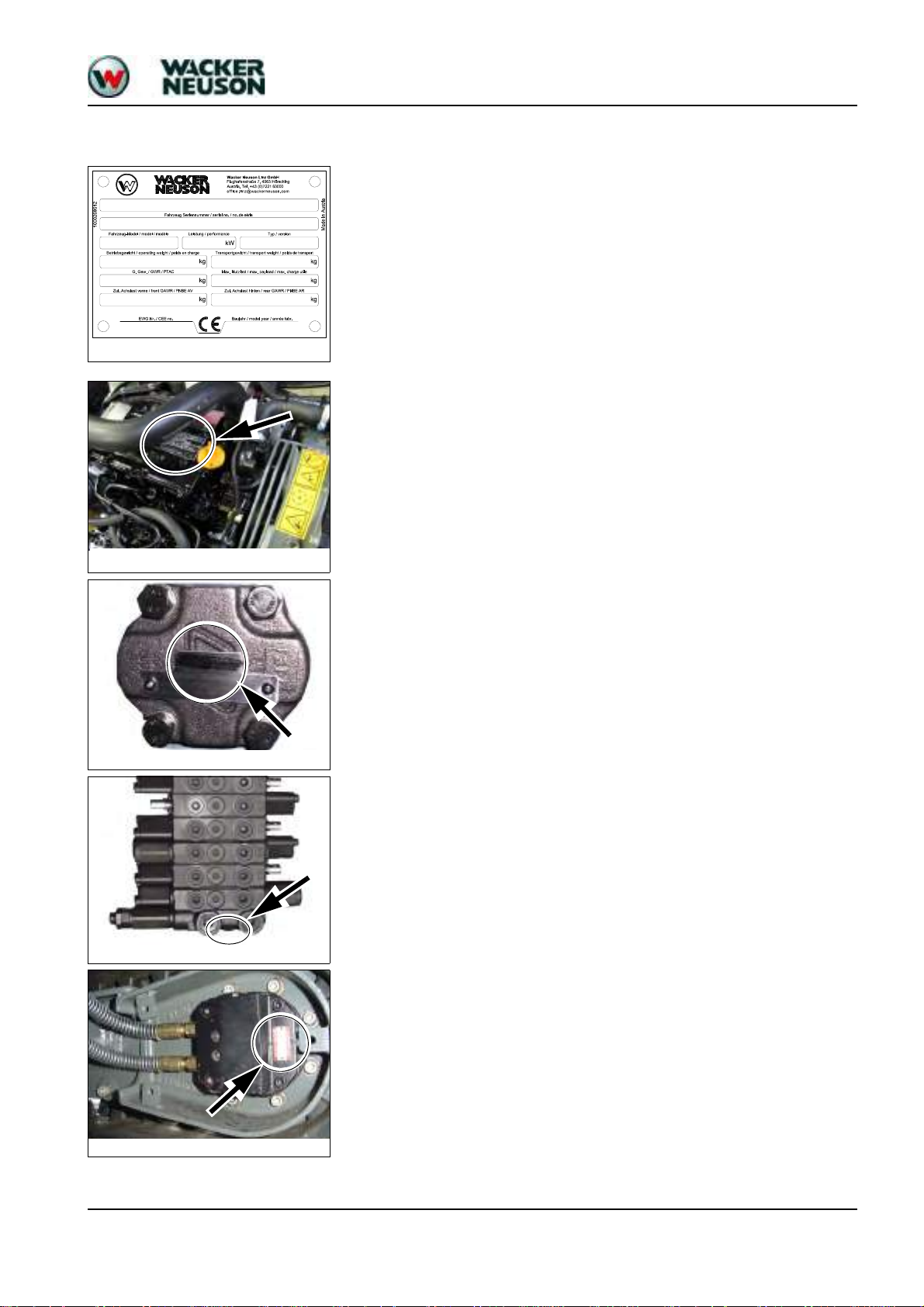
1.4 Labels
Fig. 1: Type label (symbolic representation)
Fig. 2: Diesel engine type label
Fig. 3: Hydraulic pump type label
Fig. 4: Main valve block type label
Fig. 5: Traveling drive type label
Operation
Serial number
The serial number is located on the type label.
The serial number is also stamped on the machine chassis.
Refer to the Operator’s Manual of the machine for more information.
Diesel engine type label
The type label (arrow) is located on the cylinder-head cover (engine).
Hydraulic pump type label
The type label (arrow) is located on the hydraulic pump housing.
Main valve block type label
The type label (arrow) is located on the lower side of the main valve block.
Traveling drive type label
The type label (arrow) is located on the traveling drive.
SHB 803 en – Edition 2.4 * 803s110.fm 1-5
Page 14

Operation
Fig. 6: Swivel unit type label
Swivel unit type label
The type label (arrow) is located on the swivel unit.
1-6 SHB 803 en – Edition 2.4 * 803s110.fm
Page 15

1.5 Machine overview (up to serial no. AI00966)
Fig. 7: Machine outside views
1 Boom light
2 Boom
3Stick
4Track
5 Travel gear
6 Stabilizer blade
7 Handhold
8 Lifting eye for loading/tying down the machine
9 Engine cover
10 Storage bin for Operator’s Manual
11 Lock lever
12 Track tensioner
1
2
7
3
9
8
6
54
8
2
4
5
6
8
7
11
10
12
12
3
Operation
SHB 803 en – Edition 2.4 * 803s110.fm 1-7
Page 16

Operation
2
3
1
4 5
6
8
9
11
7
13
14
12
Fig. 8: Machine outside views
1 Boom light
2 Boom
3Stick
4Track
5 Travel gear
6 Stabilizer blade
7 Handhold
8
Lifting eye for loading/tying down the
machine
9 Engine cover
10 Storage bin for Operator’s Manual
11 Lock lever
12 Track tensioner
13 ROPS rollbar (option)
14 Shatter protection (option)
8
4
5
6
10
11
14
7
2
3
8
12
1.6 Machine overview (from serial no. AI00967)
1-8 SHB 803 en – Edition 2.4 * 803s110.fm
Page 17
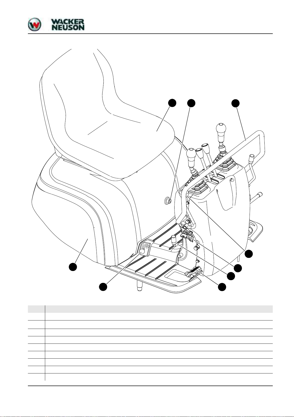
1.7 Control stand overview (up to serial no. AI00814)
1
3
9
8
2
7
6
4
5
Operation
Pos.
Designation
1
Operator seat
2
Upper carriage lock
3
Engine cover lock
4
Preheating start switch
5
Stabilizer blade/telescopic undercarriage lever
6
Stabilizer blade/telescopic travel gear changeover lever
7
Auxiliary hydraulics
8
Engine cover
9
Handhold
SHB 803 en – Edition 2.4 * 803s110.fm 1-9
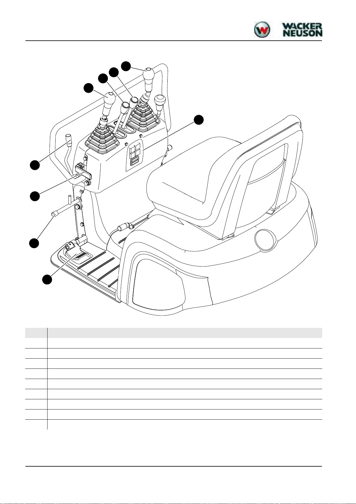
Page 18
Operation
10
11
12
13
14
15
17
16
18
Pos. Designation
10
Boom swivel/auxiliary hydraulics pedal
11
Footrest
12
Control lever lock
13
Throttle
14
Control lever (left)
15
Drive lever (left)
16
Drive lever (right)
17
Control lever (right)
18
Indicators
1-10 SHB 803 en – Edition 2.4 * 803s110.fm
Page 19

1.8 Control stand overview (from serial no. AI00815)
4
6
1
2
3
5
7
8
10
11
11
12
1314 15 16 17
9
18
19
Operation
Pos. Designation
1
2
3
4
5
6
7
8
9
10
11
12
13
14
15
16
17
18
19
Operator seat
Upper carriage lock
Engine cover lock
Starter
Stabilizer blade/telescopic travel gear lever
Stabilizer blade/telescopic travel gear changeover lever
Boom swivel pedal
Engine cover
Handhold
Auxiliary hydraulics pedal
Footrest
Lock lever
Throttle
Control lever (left)
Drive lever (left)
Drive lever (right)
Control lever (right)
Display element
Lever for switching over hammer/grab operation (option)
SHB 803 en – Edition 2.4 * 803s110.fm 1-11
Page 20
Operation
22
20
24
21
23
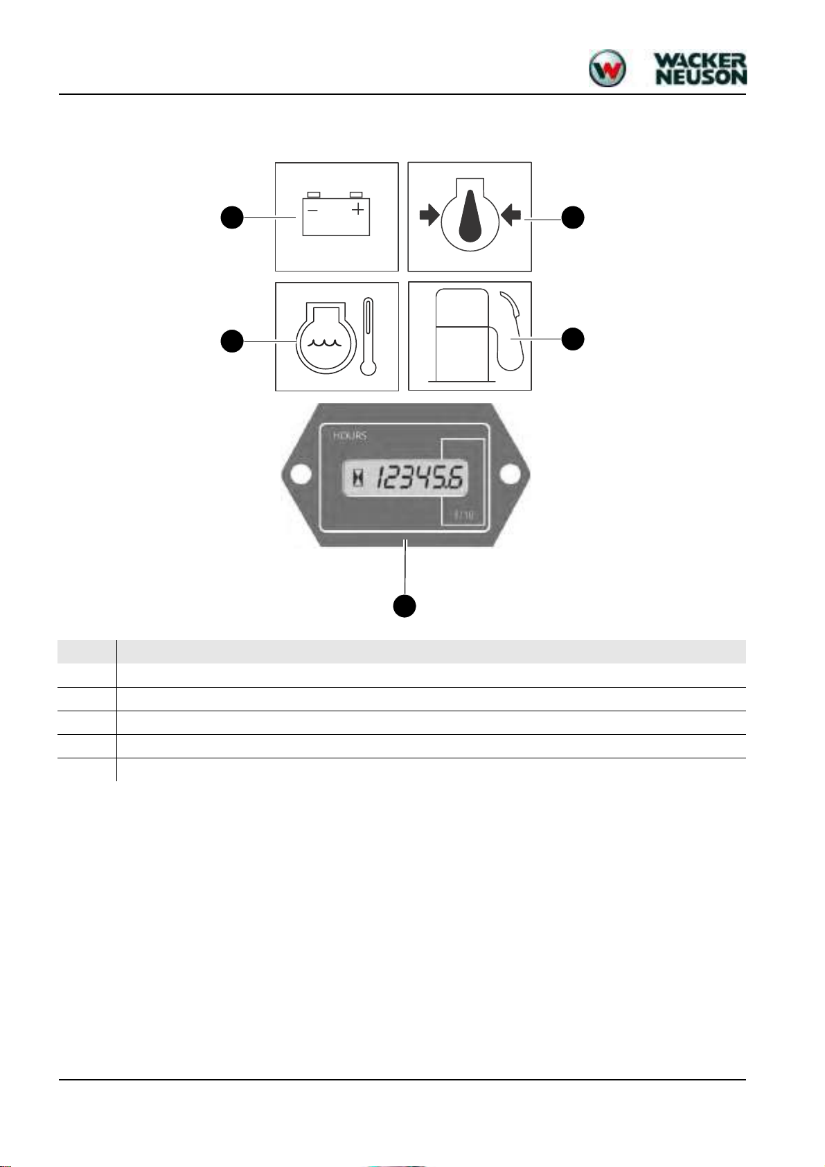
1.9 Display elements (overview)
Pos. Designation
20
Indicator light (red) – alternator charge function
21
Indicator light (red) – engine oil pressure
22
Indicator light (red) – coolant temperature
23
Indicator light (yellow) – fuel gage
24
Hour meter
1-12 SHB 803 en – Edition 2.4 * 803s110.fm
Page 21
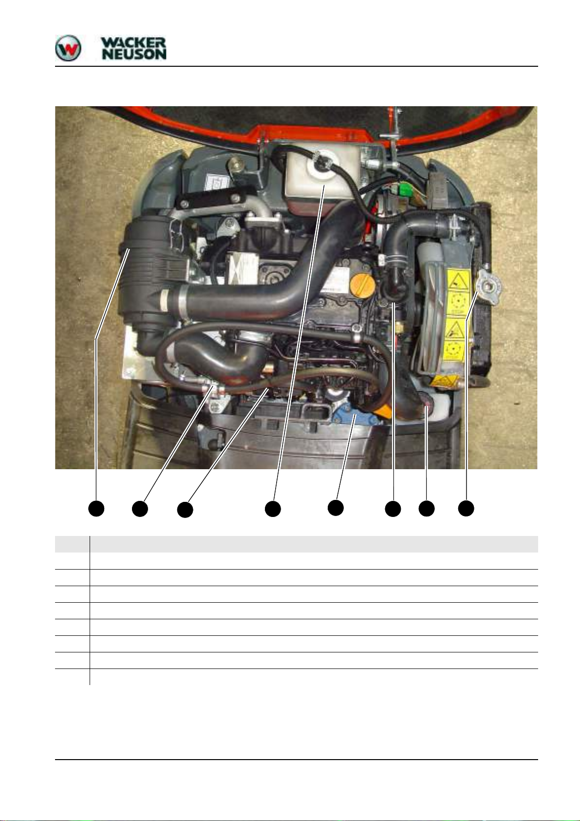
1.10 Engine compartment overview (up to serial no. AI00814)
29
31
30
25
27
26
32
28
Operation
Pos. Designation
25
Air filter
26
Throttle cable
27
Fuel filter
28
Swivel unit
29
Thermostat
30
Filler neck
31
Coolant filler inlet
32
Coolant reservoir
SHB 803 en – Edition 2.4 * 803s110.fm 1-13
Page 22
Operation
37
39
38
33
34
35
40
36
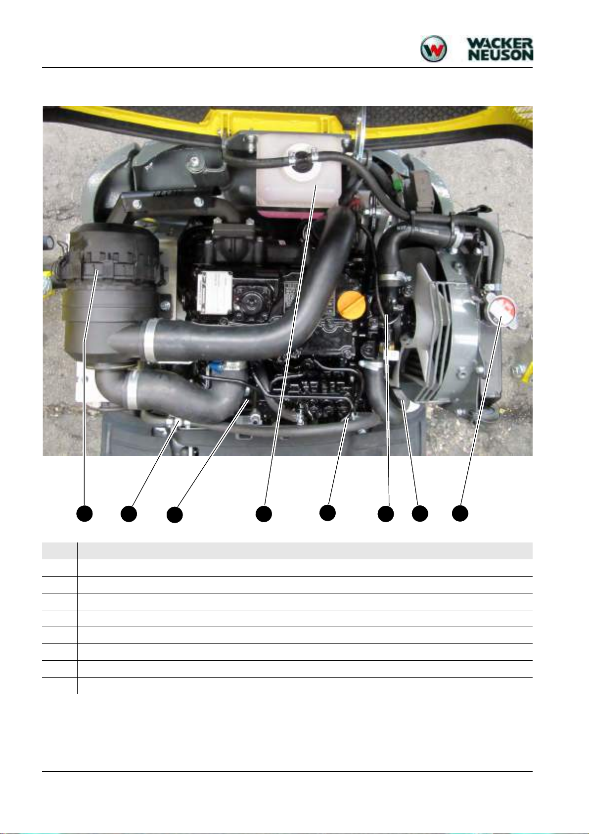
1.11 Engine compartment overview (from serial no. AI00815)
Pos. Designation
33
Air filter
34
Fuel filter
35
Throttle cable
36
Swivel unit
37
Thermostat
38
Filler neck
39
Coolant filler inlet
40
Coolant reservoir
1-14 SHB 803 en – Edition 2.4 * 803s110.fm
Page 23

Technical data
Page 24

Technical data
Technical data
2 Technical data
2.1 Chassis
2.2 Engine
Sturdy steel sheet chassis, rubber-mounted engine
Engine Model 803
Product Yanmar diesel engine
Type 3TNV70-VNS
Design Water-cooled 4 stroke diesel engine
Number of cylinders 3
Fuel injection system Indirect injection
Aspiration Natural aspiration
Cooling system Water-cooled/blowing fan
Lubrication system Force-feed lubrication with trochoidal pump
Displacement 854 cm³ (52.1 in³)
Nominal bore and stroke 70 x 74 mm (2.75 x 2.91")
Output 9.6 kW (12.9 hp) at 2100 rpm
Max. torque 51.5 Nm (38 ft lbs) at 1500 rpm
Max. engine speed without load 2270 +/− 25 rpm
Idling speed 1300 +/− 25 rpm
Valve clearance (intake = outlet) 0.15 – 0.25 mm/(0.006 – 0.01") cold
Compression 32.4 +/− 1 bar (469.9 +/− 15 psi) at 250 rpm
Engine oil pressure 2.9 – 4.4 bar (42 – 64 psi) at rated output
Pressure switch for engine oil pump 0.5 +/− 0.1 bar (7.25 +/− 1.45 psi)
Thermostat opening temperature 69.5 – 72.5 °C (157 – 163 °F)
Thermal switch 107 – 113 °C (225 – 235 °F)
Firing order 1 – 3 – 2 – 1
Direction of rotation
Starting aid Glow plugs (preheating time 4 seconds)
Specific fuel consumption 272 g/kWh (lb/hph)
Max. engine droop
(all 2 pumps under full load)
Anticlockwise
(as seen from the flywheel)
By about 90 rpm
Exhaust values according to EPA TIER IV final (up to 2012)
2-2 SHB 803 en – Edition 2.4 * 803s210.fm
Page 25

Technical data
Engine Model 803
Product Yanmar diesel engine
Type 3TNV74F-SNNS
Design Water-cooled 4 stroke diesel engine
Number of cylinders 3
Fuel injection system Indirect injection
Aspiration Natural aspiration
Cooling system Water-cooled/blowing fan
Lubrication system Force-feed lubrication with trochoidal pump
3
Displacement 993 cm³ (60.6 in
Nominal bore and stroke 74 x 77 mm (2.9 x 3.0 in)
Output
Max. torque
Max. engine speed without load
Idling speed
11.5 kW at 2500 rpm
(15.4 hp/2,500 rpm)
53 Nm at 1800 rpm
(39 ft.lbs/1800 rpm)
2675 +/− 25 rpm
(2,675 +/− 25 rpm)
1300 +/− 25 rpm
(1,300 +/− 25 rpm)
Valve clearance (intake = outlet) 0.15 – 0.25 mm/(0.006 – 0.01") cold
)
Compression 32.4 +/− 1 bar (469.9 +/− 15 psi) at 250 rpm
Engine oil pressure 3 – 4.5 bar (43.5 – 65.3 psi) at rated output
Pressure switch for engine oil
pump
0.5 +/− 0.1 bar (7.25 +/− 1.45 psi)
Thermostat opening temperature 71 °C (160 °F)
Thermal switch 107 °C (230 °F)
Firing order 1 – 3 – 2 – 1
Direction of rotation
Anticlockwise
(as seen from the flywheel)
Starting aid Glow plugs (preheating time 4 seconds)
Specific fuel consumption 279 g/kWh (lb/hph)
Max. engine droop (all 2 pumps
under full load)
By about 110 rpm
Exhaust values according to EPA TIER IV final (from 2012)
SHB 803 en – Edition 2.4 * 803s210.fm 2-3
Page 26

Technical data
Fuel injection pump
Engine capacities
Engine tightening torques
Type
Design In-line pump
Injection pressure 118 – 128 bar (1711 – 1856 psi)
Engine speed control Mechanical
Lubrication system Force-feed engine oil lubrication
Capacities Model 803
Fuel tank 7 l (1.85 gal)
Engine oil (max./effect.) 2.8 l/1.3 l (0.74/0.34 gal)
Coolant (with radiator) 2.9 l (0.77 gal)
Coolant reservoir 1.1 l (0.29 gal)
Overview of capacities – see Fluids and lubricants on page 3-2
Tightening torques Model 803
Cylinder-head bolt
1
Connecting rod bearing screw
1
54 – 58 Nm (M9x1.25) (40 − 43 ft lbs)
22.6 − 27.5 Nm (M7x1.0) (16.6 − 20.3 ft lbs)
2.3 Hydraulic system
Main bearing screw 75.5 – 81.5 Nm (M10x1.25) (55.7 – 60 ft lbs)
Flywheel screw 80.4 – 86.4 Nm (M10x1.25) (59.3 – 63.7 ft lbs)
1. Screws must be oiled!
Hydraulics Model 803
Pump (Tier IV final up to 2012) Twin gear pump 2 x 5 cm³ (2 x 0.3 in³/rev)
Flow rate (Tier IV final up to 2012)
2 x 11.35 l/min at 2270 rpm
(2 x 3 gal/min at 2270 rpm)
Pump (Tier IV final from 2012) Twin gear pump 2 x 4 cm³ (2 x 0.24 in³/rev)
Flow rate (Tier IV final from 2012)
2 x 10.7 l/min at 2675 rpm
(2 x 2.8 gal/min at 2675 rpm)
Control valve 9 sections
Main pressure limiting valve for pumps
P1, P2
Secondary pressure limiting valve
for swivel unit
Secondary pressure limiting valve, stick 250 +/−5 bar (3625.9 +/−72.5
170 +/− 3 bar (2465.64 +/− 44 psi)
70
-0/+0.5
bar (1015.3
-0/+7 psi
gal/min)
) at 11.5 l/min (3
psi)
Hydraulic reservoir capacity 13.8 l (3.6 gal)
2-4 SHB 803 en – Edition 2.4 * 803s210.fm
Page 27
Auxiliary hydraulics oil flow
Notice!
2.4 Travel gear and swivel unit
Travel gear/swivel unit Model 803
Travel speeds 1.82 kph (1.13 mph)
Technical data
Pressure (bar/psi) P1 + P2 (l/min / gal/min)
12.5/181.3 22/5.8
37.8/548.2 20.8/5.5
50/725.2 20.4/5.4
79/1145.8 19.7/5.2
140/2030.5 18.5/4.8
160/2320.6 10.5/2.7
168/2436.6 5/1.3
Output indications for auxiliary hydraulics with unpressurized return line
2.5 Stabilizer blade
Screwable hose burst valve
Hill climbing ability
(no longer than 3 minutes)
Track width 180 mm (7.09'')
No. of track rollers on either side 2
Ground clearance 132 mm (5.2'')
Ground pressure 0.24 kg/cm² (3.4 psi)
Upper carriage swivel speed 8 rpm
Stabilizer blade Model 803
Width (folded in/out) 700/860 mm (27.55"/33.85")
Height 198 mm (7.8'')
Max. lift over/under subgrade 197/174 mm (7.76"/6.85")
Location Thread Gap dimension
Stabilizer blade 3/8" 0.3 mm (0.012'')
30°/58 %
SHB 803 en – Edition 2.4 * 803s210.fm 2-5
Page 28
Technical data
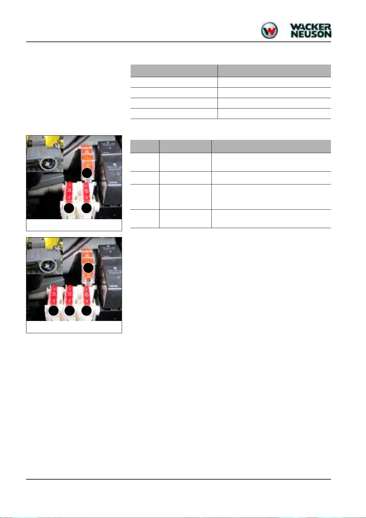
F1
F2F3
Fig. 9: Fuses (up to serial number
WNCE0801CPAL0050)
F1
F2F3
Fig. 10: Fuses (from serial number WNCE0801TPAL0051)
F4
2.6 Electrical system
Fuses behind the right-hand trim
Electrical system
Dynamo 12 V 20 A
Starter 12 V 1.1 kW (1.5 hp)
Battery 12 V 30 Ah
Socket For 12 V power outlet, for example; 15 A max.
Fuse no. Rated current (A) Protected circuit
F1 40 A
F2 10 A
F3 10 A
F4 10 A
Main fuse: air-pressure sensor/output adaptation
(Yanmar 3TNV74F-SNNS)
Fuse: relay, indicator, cutoff solenoid
Fuse: horn, working light 12 V power outlet (up to
serial number WNCE0801CPAL0050, travel signal
(option)
12 V power outlet (from serial number
WNCE0801TPAL0051)
2-6 SHB 803 en – Edition 2.4 * 803s210.fm
Page 29
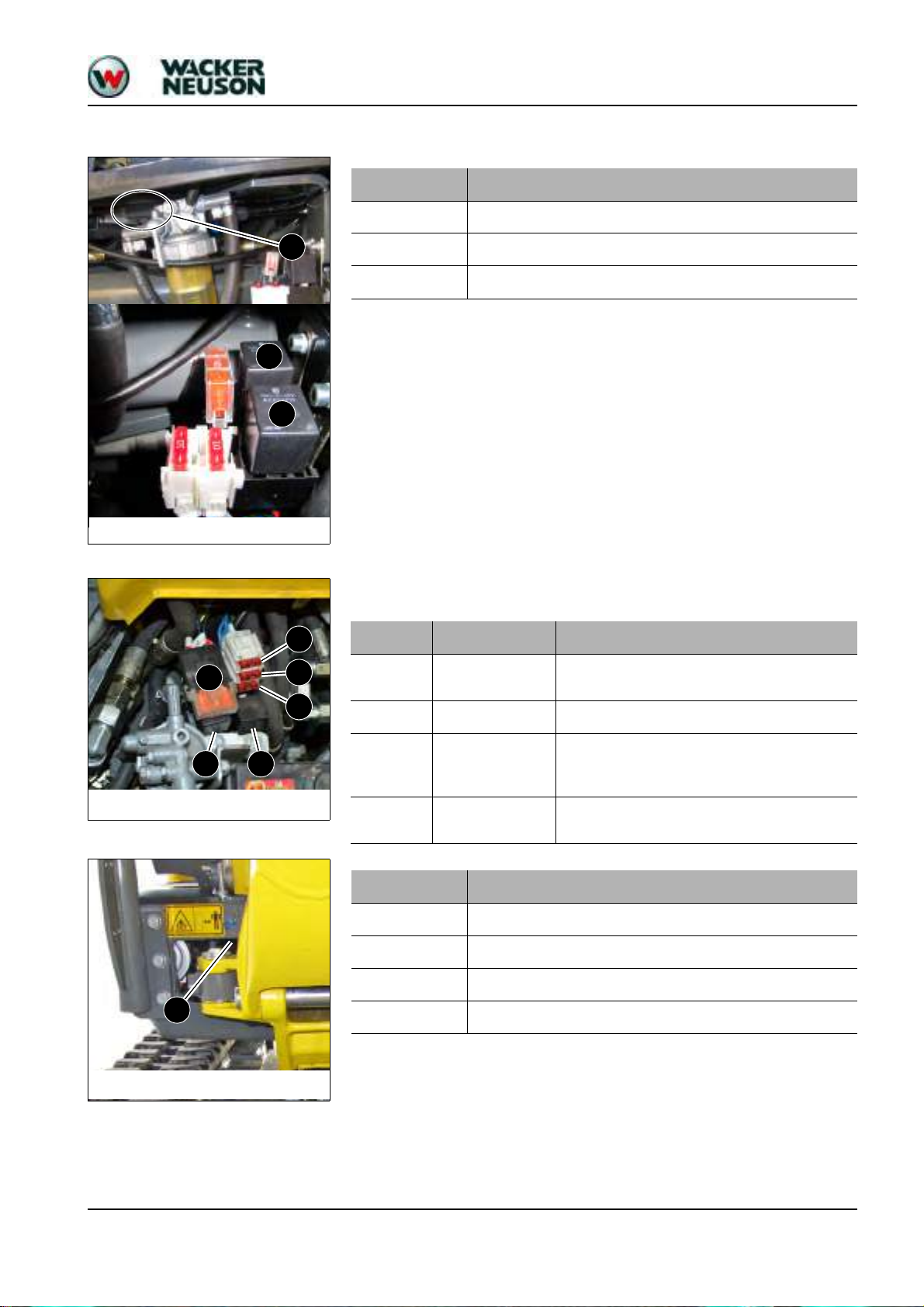
Relays behind the right-hand trim
K8
K9
K7
Fig. 11: Relays
Fig. 12: Fuses and relays with Dual Power option
F1
F4
F2
F3
K7K9
Fig. 13: Relay K8
K8
Technical data
Relay no. Protected circuit
K 7 Starting relay
K 8 Cutoff solenoid time lag relay 1s
K 9 Cutoff solenoid switching relay
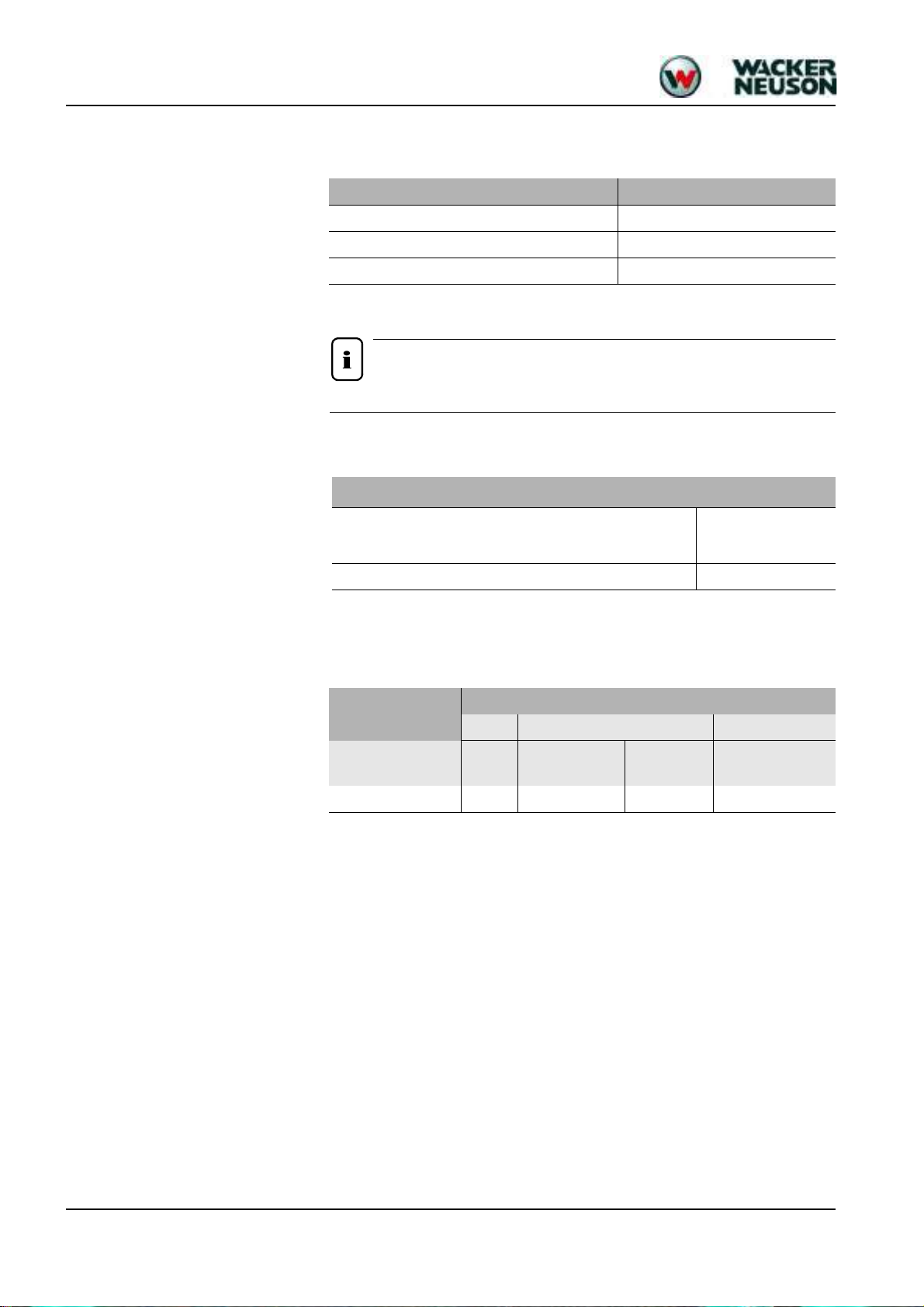
Fuses and relays with Dual Power option
If the machine is equipped with the Dual Power option, the fuses and relays are located
under the base plate.
Fuse no. Rated current (A) Protected circuit
F1 40 A
F2 10 A
Main fuse: air-pressure sensor/output adaptation
(Yanmar 3TNV74F-SNNS)
Fuse: relay, indicator, cutoff solenoid
Fuse: horn, working light 12 V power outlet (up to
F3 10 A
serial number WNCE0801CPAL0050, travel signal
(option), battery control (Dual Power option)
F4 10 A
12 V power outlet (from serial number
WNCE0801TPAL0051)
Relay no. Protected circuit
K 7 Starting relay
K 8 Cutoff solenoid time lag relay 1s
K 9 Cutoff solenoid switching relay
K 116 Battery control
SHB 803 en – Edition 2.4 * 803s210.fm 2-7
Page 30
Technical data
Notice!
2.7 Noise levels
2.8 Vibration
Sound power level Model 803
1
Sound power level (L
Operator-perceived sound pressure level (L
Uncertainty (K
1. ISO 6395 (EC Directives 2000/14/EC and 2005/88/EC)
2. EN ISO 4871 (EC Directives 2000/14/EC and 2005/88/EC)
3. ISO 6394 (EC Directives 84/532/EEC, 89/514/EEC, 95/27/EEC)
PA
)
WA
PA
3
)
2
)
93 dB (A)
77 dB (A)
1.2 dB (A)
Measurements performed on asphalted surface.
Vibration
2.9 Coolant compound table
Effective acceleration value for the upper extremities of the
body (hand-arm vibration)
< Trigger value
< 2.5 m/s
Effective acceleration value for the body (whole-body vibration) < 0.5 m/s
Vibration values indicated in m/s².
Coolant
Outside temperature
Water Anticorrosion agent Antifreeze agent
Up to °C (°F)
% by
volume
cm³/l / (in3/gal) % by volume % by volume
-37 (-34.6) 50 10 (2.6) 1 50
Use the 1:1 concentration for warm outside temperatures, too:
Protection against corrosion, cavitation and deposits
Do not mix the coolant with other coolants.
Machine filled at the factory with Eurolub SF D12 coolant (ethylene glycol basis).
2
2
2-8 SHB 803 en – Edition 2.4 * 803s210.fm
Page 31

2.10 Model-specific tightening torques
Technical data
Model 803 Thread
Live ring M12x1.25 10.9 130 (95.9)*
Track roller M10 10.9 65 (47.9)*
Drive pinion M10 10.9 65 (47.9)*
Traveling drive M10 10.9 65 (47.9)*
Gear motor M12 10.9 110 (81.1)*
Angled engine bracket M10 8.8 45 (33.2)
Engine bearing M10 8.8 45 (33.2)
Pump base M10 8.8 45 (33.2)
Pump M10 8.8 45 (33.2)
Swivel joint M10 10.9 64 (47.2)*
Bumper M14 12.9 230 (169.6)*
*) All connections with an * must be glued with Loctite S2420 or VaryBond 12-43.
2.11 General tightening torques
Tightening torques for hydraulic threaded fittings (dry assembly)
Metric hose fittings for hydraulic applications (light execution, DKOL)
Nominal Ø Outer Ø Thread Wrench size
05 6L M12X1.5 WS 14 15 (11)
06 8L M14X1.5 WS 17 20 (14.7)
08 10L M16X1.5 WS 19 40 (29.5)
10 12L M18X1.5 WS 22 50 (36.8)
12 15L M22X1.5 WS 27 75 (55.3)
16 18L M26X1.5 WS 32 85 (62.7)
20 22L M30X2 WS 36 100 (73.75)
25 28L M36X2 WS 41 180 (132.7)
32 35L M45X2 WS 55 220 (162.3)
Galvanized and dry surface (O-ring slightly oiled). Torque tolerance: −10 %
Values determined empirically and to be applied as approximate figures.
Torque
Nm (ft lbs)
Torque
Nm (ft lbs)
Metric hose fittings for hydraulic applications (heavy execution, DKOL)
Nominal Ø Outer Ø Thread Wrench size
Torque
Nm (ft lbs)
05 8S M16X1.5 WS 19 40 (29.5)
06 10S M18X1.5 WS 22 50 (36.8)
08 12S M20X1.5 WS 24 60 (44.3)
10 14S M22X1.5 WS 27 75 (55.3)
12 16S M24X1.5 WS 30 90 (66.4)
16 20S M30X2 WS 36 100 (73.8)
20 25S M36X2 WS 41 180 (132.8)
25 30S M42X2 WS 50 270 (199.1)
32 38S M52X2 WS 60 400 (295)
Galvanized and dry surface (O-ring slightly oiled). Torque tolerance: −10 %
Values determined empirically and to be applied as approximate figures.
SHB 803 en – Edition 2.4 * 803s210.fm 2-9
Page 32

Technical data
Threaded fittings with various seals for hydraulic applications (light execution)
Thread
Straight pipe fitting with thread and
screwed plug
Sealing
washer
Elastic seal O-ring
Non-return
valve with
elastic seal
Identification aid
outside Ø
Nm (ft lbs) Nm (ft lbs) Nm (ft lbs) Nm (ft lbs) mm (")
M10X1.0 9 (7) 18 (13) 15 (11) 18 (13) 10 (0.4)
M12X1.5 20 (15) 25 (18) 25 (18) 25 (18) 12 (0.5)
M14X1.5 35 (26) 45 (33) 35 (26) 35 (26) 14 (0.55)
M16X1.5 45 (33) 55 (41) 40 (30) 50 (37) 16 (0.6)
M18X1.5 55 (41) 70 (52) 45 (33) 70 (52) 18 (0.7)
M22X1.5 65 (48) 125 (92) 60 (44) 125 (92) 22 (0.9)
M27X2.0 90 (66) 180 (133) 100 (74) 145 (107) 27 (1.0)
M33X2.0 150 (111) 310 (229) 160 (118) 210 (155) 33 (1.3)
M42X2.0 240 (177) 450 (332) 210 (155) 360 (266) 42 (1.7)
M48X2.0 290 (214) 540 (398) 260 (192) 540 (398) 48 (1.9)
G1/8A 9 (7) 18 (13) 15 (11) 18 (13) 9.73 (0.38)
G1/4A 35 (26) 35 (26) 30 (22) 35 (26) 13.16 (0.52)
G3/8A 45 (33) 70 (52) 45 (33) 50 (37) 16.66 (0.66)
G1/2A 65 (48) 90 (66) 55 (41) 65 (48) 20.96 (0.83)
G3/4A 90 (66) 180 (133) 100(74) 140 (103) 26.44 (1.04)
G1A 150 (111) 310 (229) 160 (118) 190 (140) 33.25 (1.31)
G1 1/4A 240 (177) 450 (332) 210 (155) 360 (266) 41.91 (1.65)
G1 1/2A 290 (214) 540 (398) 260 (192) 540 (398) 47.80 (1.88)
Torque tolerance: −10 %; countermaterial: steel/aluminum
Threaded fittings with various seals for hydraulic applications (heavy execution)
Thread
Straight pipe fitting with thread and
screwed plug
Sealing
washer
Elastic seal O-ring
Non-return
valve with
elastic seal
Identification aid
outside Ø
Nm (ft lbs) Nm (ft lbs) Nm (ft lbs) Nm (ft lbs) mm (")
M12X1.5 20 (15) 35 (26) 35 (26) 35 (26) 12 (0.5)
M14X1.5 35 (26) 55 (41) 45 (33) 45 (33) 14 (0.55)
M16X1.5 45 (33) 70 (52) 55 (41) 55 (41) 16 (0.6)
M18X1.5 55 (41) 90 (66) 70 (52) 70 (52) 18 (0.7)
M20X1.5 55 (41) 125 (92) 80 (59) 100 (74) 22 (0.9)
M22X1.5 65 (48) 135 (100) 100 (74) 125 (92) 27 (1.0)
M27X2.0 90 (66) 180 (133) 170 (126) 135 (100) 12 (0.5)
M33X2.0 150 (111) 310 (229) 310 (229) 210 (155) 33 (1.3)
M42X2.0 240 (177) 450 (332) 330 (243) 360 (266) 42 (1.7)
M48X2.0 290 (214) 540 (398) 420 (310) 540 (398) 48 (1.9)
G1/8A 35 (26) 55 (41) 45 (33) 45 (33) 13.16 (0.52)
G1/4A 45 (33) 80 (59) 60 (44) 60 (44) 16.66 (0.66)
G3/8A 65 (48) 115 (85) 75 (55) 100 (74) 20.96 (0.83)
G1/2A 90 (66) 180 (133) 170 (125) 145 (107) 26.44 (1.04)
G3/4A 150 (111) 310 (229) 310 (229) 260 (192) 33.25 (1.31)
G1A 240 (177) 450 (332) 330 (243) 360 (266) 41.91 (1.65)
G1 1/4A 290 (214) 540 (398) 420 (310) 540 (398) 47.80 (1.88)
Torque tolerance: –10 %; countermaterial: steel/aluminum
2-10 SHB 803 en – Edition 2.4 * 803s210.fm
Page 33

Tightening torques for high-resistance threaded fittings
Thread
M5 5.5 (4) 8 (6) 10 (7) 5 (4) 7 (5)
M6 10 (7) 14 (10) 17 (13) 8.5 (6) 12 (9)
M8 25 (18) 35 (26) 42 (31) 20 (15) 30 (22)
M10 45 (33) 65 (48) 80 (59) 40 (30) 59 (44)
M12 87 (64) 110 (81) 147 (108) 69 (51) 100 (74)
M14 135 (100) 180 (133) 230 (170) 110 (81) 160 (118)
M16 210 (155) 275 (203) 350 (258) 170 (125) 250 (184)
M18 280 (207) 410 (302) 480 (354) 245 (181) 345 (254)
M20 410 (302) 570 (420) 690 (509) 340 (251) 490 (361)
M22 550 (406) 780 (575) 930 (686) 460 (339) 660 (487)
M24 710 (524) 1000 (738) 1190 (878) 590 (435) 840 (620)
M27 1040 (767) 1480 (1092) 1770 (1305) 870 (642) 1250 (922)
M30 1420 (1047) 2010 (1482) 2400 (1770) 1200 (885) 1700 (1254)
DIN 912 – hexagon socket head cap screw; DIN 931/DIN 933 – hexagon head screw with/without shaft;
DIN 7984 – hexagon socket head cap screw with short head
All values subject to a friction coefficient of µ = 0.12 and are to be used as approximate figures.
Technical data
With coarse-pitch thread
Screws according to DIN 912, DIN 931,
DIN 933, etc.
8.8 10.9 12.9 8.8 10.9
Nm (ft lbs) Nm (ft lbs) Nm (ft lbs) Nm (ft lbs) Nm (ft lbs)
Screws according to DIN 7984
With fine-pitch thread
Thread
Screws according to DIN 912, DIN 931,
DIN 933, etc.
8.8 10.9 12.9 8.8 10.9
Screws according to DIN 7984
Nm (ft lbs) Nm (ft lbs) Nm (ft lbs) Nm (ft lbs) Nm (ft lbs)
M8X1.0 25 (18) 37 (28) 43 (32) 22 (16) 32 (24)
M10X1.0 50 (37) 75 (55) 88 (65) 43 (32) 65 (48)
M10X1.25 49 (36) 71 (52) 83 (61) 42 (31) 62 (46)
M12X1.25 87 (64) 130 (96) 150 (111) 75 (55) 110 (81)
M12X1.5 83 (61) 125 (92) 145 (107) 72 (53) 105 (77)
M14X1.5 135 (100) 200 (148) 235 (173) 120 (89) 175 (129)
M16X1.5 210 (155) 310 (229) 360 (266) 180 (133) 265 (195)
M18X1.5 315 (232) 450 (332) 530 (391) 270 (199) 385 (284)
M20X1.5 440 (325) 630 (465) 730 (538) 375 (277) 530 (391)
M22X1.5 590 (435) 840 (620) 980 (723) 500 (369) 710 (524)
M24X2.0 740 (546) 1070 (789) 1250 (922) 630 (465) 900 (664)
M27X2.0 1100 (811) 1550 (1143) 1800 (1328) 920 (679) 1300 (959)
M30X2.0 1500 (1106) 2150 (1586) 2500 (1844) 1300 (959) 1850 (1364)
DIN 912 – hexagon socket head cap screw; DIN 931/DIN 933 – hexagon head screw with/without shaft;
DIN 7984 – hexagon socket head cap screw with short head
All values subject to a friction coefficient of µ = 0.12 and are to be used as approximate figures.
SHB 803 en – Edition 2.4 * 803s210.fm 2-11
Page 34

Technical data
787 (31 in)
1294 (51 in)
1220 (48 in)
500 (20 in)
897 (35 in)
747 (29 in)
1906 (75 in)
323 (13 in)
1198 (47 in)
Fig. 14: Machine dimensions (model 803)
198
1507
700/860
180
180
340
700/860
730
2.12 Dimensions model 803 (up to serial no. AI00966)
Main data Model 803
Operating weight 935 kg (2061 lbs.)
Height (transport position) 1507 mm (4'-11")
Upper carriage width 730 mm (2'-5'')
Width of telescopic travel gear (retracted/extended) 700/860 mm (2'-4"/2'-10")
Width of stabilizer blade (folded in/out) 700/860 mm (2'-4"/2'-10")
Transport length 2747 mm (9')
Max. digging depth 1731 mm (5'-8")
Stick length 890 mm (2'-11'')
Max. vertical digging depth 1349 mm (4'-5")
Max. digging height 2863 mm (9'-5")
Max. tilt-out height 2035 mm (6'-8")
Max. digging radius 3074 mm (10'-1")
Max. reach at ground level 3028 mm (9'-11")
Max. breakout force at bucket tooth 8.99 kN (2021 lbf)
Max. tearout force 4.51 kN (1014 lbf)
Min. tail end slewing radius 747 mm (2'-5'')
Max. tail end lateral projection (90° rotation of upper carriage)
Telescopic travel gear retracted/extended
Stabilizer blade folded in/out
397/317 mm (1'-4"/1")
397/317 mm (1'-4"/1")
Max. boom displacement to bucket center (right side) 287 mm (0' 11")
Max. boom displacement to bucket center (left side) 242 mm (0'-10")
2-12 SHB 803 en – Edition 2.4 * 803s210.fm
Page 35

2.13 Dimensions model 803 with ROPS rollbar (from serial no. AI00967)
Fig. 15: Machine dimensions (model 803)
Technical data
Main data Model 803
Operating weight
Transport weight
Height (transport position)
1087 kg ( 2396 lbs)
990 kg (2182 lbs)
2248 mm (7'-5")
Upper carriage width 730 mm (2'-5'')
Width of telescopic travel gear (retracted/extended) 700/860 mm (2'-4"/2'-10")
Width of stabilizer blade (folded in/out) 700/860 mm (2'-4"/2'-10")
Transport length
Max. digging depth
Stick length
Max. vertical digging depth
Max. digging height
Max. tilt-out height
Max. digging radius
Max. reach at ground level
Max. breakout force at bucket tooth
Max. tearout force
Min. tail end slewing radius
Max. tail end lateral projection (90° rotation of upper carriage)
Retracted/extended telescopic travel gear
Stabilizer blade folded in/out
Max. boom displacement to bucket center (right side)
Max. boom displacement to bucket center (left side)
2747 mm (9')
1766 mm (5'-10")
890 mm (2'-11'')
1320 mm (4'-4")
2853 mm (9'-4")
2008 mm (6'-7")
3092 mm (10'-2")
3046 mm (10")
8.99 kN (2021 lbf)
4.51 kN (1014 lbf)
747 mm (2'-5'')
397/317 mm (1'-4"/1')
397/317 mm (1'-4"/1')
287 mm (0' 11")
242 mm (0'-10")
SHB 803 en – Edition 2.4 * 803s210.fm 2-13
Page 36

Technical data
730 (29 in)
R747 (29 in)
R1039(41 in)
180 (7 in)
1436 (57 in)
178
(7 in)
194
(8 in)
1220 (48 in)
3092 (10'-2'')
1320 (52 in)
1766 (70 in)
2008 (79 in)
2853 (9'-4'')
Fig. 16: Machine dimensions (model 803)
2.14 Dimensions model 803 without ROPS rollbar (from serial no. AI00967)
Main data
Operating weight
Transport weight
Height (transport position)
Model 803
1029 kg ( 2268 lbs)
932 kg (2055 lbs)
1436 mm (4'-9")
Upper carriage width 730 mm (2'-5'')
Width of telescopic travel gear (retracted/extended)
Width of stabilizer blade (folded in/out)
Transport length
Max. digging depth
Stick length
Max. vertical digging depth
Max. digging height
Max. tilt-out height
Max. digging radius
Max. reach at ground level
Max. breakout force at bucket tooth
Max. tearout force
Min. tail end slewing radius
Max. tail end lateral projection (90° rotation of upper carriage)
Retracted/extended telescopic travel gear
Stabilizer blade folded in/out
Max. boom displacement to bucket center (right side)
Max. boom displacement to bucket center (left side)
700/860 mm (2'-4"/2'-10")
700/860 mm (2'-4"/2'-10")
2747 mm (9')
1763 mm (5'-9'')
890 mm (2'-11'')
1320 mm (4'-4")
2853 mm (9'-4")
2008 mm (6'-7")
3090 mm (10'-2")
3046 mm (10")
8.99 kN (2021 lbf)
4.51 kN (1014 lbf)
747 mm (2'-5'')
397/317 mm (1'-3"/1')
397/317 mm (1'-3"/1')
(0'-11")
287 mm
(0'-10")
242 mm
2-14 SHB 803 en – Edition 2.4 * 803s210.fm
Page 37

2.15 Lift capacity table 803 RD
E Pin diameter 25 mm (0.98'')
F Stick width 100 mm (3.9'')
L
Pin distance from
bucket mount
165 mm (6.5'')
Bucket
Stick
Refer to the Operator’s Manual of the machine for specific data.
2.16 Kinematics
Technical data
SHB 803 en – Edition 2.4 * 803s210.fm 2-15
Page 38

Technical data
2-16 SHB 803 en – Edition 2.4 * 803s210.fm
Page 39

Maintenance
Page 40

Maintenance
Maintenance
3 Maintenance
3.1 Fluids and lubricants
Component/appli-
cation
Fluid/lubricant Specification Season/temperature Capacities
API: CG-4/CH-4/CI-4
Diesel engine Engine oil
ACEA: E3, E4, E5
ACEA E3, E4, E5 (SAE10 W 40)
3
5
Hydraulic oil
reservoir
Hydraulic oil
Biodegradable oil
HVLP46
HVLP46
6
PANOLIN HLP Synth 46
BP BIOHYD SE-46
Roller and friction bearings
Grease
Live ring gears
Live ring (ball bearing race)
KPF2N-20
7
Grease zerks
Battery terminals
Acid-proof grease
8
FINA Marson L2
2-D ASTM D975 – 94 (USA)
1-D ASTM D975 – 94 (USA)
Fuel tank Diesel fuel
EN 590 : 96 (EU)
ISO 8217 DMX (International)
BS 2869 – A1 (GB)
BS 2869 – A2 (GB)
Distilled water and antifreeze ASTM
Engine cooling
system
Coolant
D4985 (reddish)
Distilled water and antifreeze ASTM
D6210 (violet)
Ball socket ISO/
SAE controls
1. The capacities indicated are approximate values; the oil level check alone is relevant for the correct oil level
Capacities indicated are no system fills
2. According to DIN 51511
3. According to DIN 51524 section 3
4. Depending on local conditions – see Hydraulics oil grade on page 3-4
5. According to DIN 51524 section 3
6. Hydraulic ester oils (HEES)
7. KP2N-20 according to DIN 51502 EP multipurpose calcium sulphonate complex grease
8. Standard acid-proof grease
9. Up to serial number WNCE0801EPAL00899
10. From serial no. WNCE0801VPAL00900
Lubricant Gleitmo 800
9
10
1
−15 °C (5 °F)
2
+40 °C (104 °F)
Year-round
4
2.5 l (0.66 gal)
13.8 l (3.64 gal)
Year-round As required
Year-round As required
Depending on outside
temperatures
Summer or winter diesel
7 l (1.85 gal)
fuel
Year-round
2.9 l (0.77 gal)
Year-round As required
3-2 SHB 803 en – Edition 2.4 * 803s310.fm
Page 41

Oil grades for the diesel engine, depending on temperature
Caution!
Notice!
Engine oil grade Ambient temperature (°C/°F)
-20-15-10-5 0 5 10152025303540
°C
SAE 10W
SAE 20W
SAE 10W-30
SAE 10W-40
API: CG-4/CH-4/
CI-4
ACEA: E3, E4, E5
SAE 15W-40
SAE 20
Maintenance
SAE 30
-4 514233241505968778695104
°F
Additional oil change and filter replacement (hydraulic system)
An additional oil change and filter replacement can be required depending on
how the machine is used. Failure to observe these replacement intervals can
cause damage to hydraulic components.
☞ Observe the following intervals
Application Hydraulic oil Hydraulic oil filter insert
Normal work (excavation work)
20% Every 800 o/h
40% Every 400 o/h
Percentage of hammer work
60% Every 300 o/h
Over 80 % Every 200 o/h
Replace the first time after 500
o/h, then every 1000 o/h
Replace the first time after 50 o/h, then every 500 o/h
SAE 40
300 o/h
100 o/h
Please refer to the maintenance plan on page 3-8 for additional maintenance.
SHB 803 en – Edition 2.4 * 803s310.fm 3-3
Page 42

Maintenance
Hydrau-
lics oil
grade
°C
Oil grades for the hydraulic system, depending on temperature
Ambient temperature (°C/°F)
-20-15-10-5 0 5 1015202530354050
ISO VG32
1
HVLP
-4 5 14233241505968778695104
°F
1. According to DIN 51524 section 3
ISO VG46
ISO VG68
122
3-4 SHB 803 en – Edition 2.4 * 803s310.fm
Page 43

3.2 Maintenance label
Explanation of symbols on the maintenance label
Symbol Assembly Explanation
General Visual check
General Grease instructions
Fuel system Drain condensation water
Fuel system Replace the fuel filter, clean the fuel prefilter
Radiator Check the coolant level
Radiator Drain and add new coolant
Maintenance
Engine Check valve clearance. Adjust if necessary
Engine Check the engine oil level
Engine Change the engine oil
Engine Replace the oil filter
Engine Check the V-belt tension
Travel gear Check track tension
Hydraulic system Check oil level
Hydraulic system Change the hydraulic oil
Hydraulic system Replace the hydraulic oil filter, replace the breather filter
Radiator fins Clean
SHB 803 en – Edition 2.4 * 803s310.fm 3-5
Page 44

Maintenance
Maintenance label (up to serial number AF02412)
3-6 SHB 803 en – Edition 2.4 * 803s310.fm
Page 45

Maintenance label (from serial number AF02413)
Maintenance
SHB 803 en – Edition 2.4 * 803s310.fm 3-7
Page 46

Maintenance
Authorized
service center
Customer
Every 2000 o/h
Every 1000 o/h
once a year
Every 500 o/h
Every 250 o/h
Every 50 o/h
Maintenance
(once a day)
Maintenance plan/operating hours (o/h)
●● ●
●● ●
●● ●
●● ●
●● ●
●●
●●
●●
●●
●●
●●
●●
6
4
2
1
Maintenance
3.3 Maintenance plan (overview)
Work description
For servicing and maintenance on the attachment, please refer to the operation and maintenance manual of
the attachment manufacturer.
Fluid and filter changes ( ):
Perform the following oil and filter changes (check oil levels after test run):
3
• Engine oil
• Engine oil filter
• Fuel filter
• Water separator ●●
5
• Engine oil
• Engine coolant ●●
• Fuel ●●
• Coolant ●●
• Hydraulic oil filter insert
• Hydraulic oil
• Drain condensation water from the hydraulic oil reservoir (from serial no. AH02272) ●●
• Air filter element (up to serial no. AI00875) ●●
• Air filter element according to dirt indicator (from serial no. AI00876)
Inspection work ( ):
Check the following material. Refill if necessary:
• Hydraulic oil ●●
Check the function of the pedals (up to serial no. AI00975)
• Clean, lubricate or repair the pedals
Check the function of the pedals, they must flip back automatically (from serial no. AI00976)
7
• Clean, lubricate or repair the pedals, check the torsion springs
Clean water ducts
Check radiator for engine and hydraulic oil for dirt. Clean if necessary
Check cooling systems and hoses for leaks and pressure (visual check)
3-8 SHB 803 en – Edition 2.4 * 803s311.fm
Page 47

Authorized
service center
Customer
Every 2000 o/h
Maintenance
●
Every 1000 o/h
once a year
Every 500 o/h
Every 250 o/h
Every 50 o/h
Maintenance
(once a day)
Maintenance plan/operating hours (o/h)
●●
●●
●●
●●
●●
●●
●●
●●
●●
●●
●●
●
●●
●●
●● ●
●●●
●●
●●
●●
●●
●●
●●
10
8
9
• Clean ●●
Air filter (damage)
Remove dust from dust valve
3.3 Maintenance plan (overview)
Work description
For servicing and maintenance on the attachment, please refer to the operation and maintenance manual of
the attachment manufacturer.
SHB 803 en – Edition 2.4 * 803s311.fm 3-9
Prefilter with water separator: drain water
Check V-belt condition and tension
Replace the V-belt
Check the exhaust system for damage and condition
Check the rollbar for damage
Check valve clearance. Adjust if necessary
Clean and adjust the fuel injection pump
Check and adjust the injection pressure of the injection nozzles, clean the injection needles/nozzles
Check and adjust injection time
Empty the fuel tank and check for dirt
Check battery electrolyte. Add distilled water if necessary
Check alternator, starter and electric connections, bearing play and function
Check preheating system and electric connections
Pressure check of primary pressure limiting valves
Check tracks for cracks and cuts
Check track tension. Retighten if necessary
Check bearing play of tread rollers, track carrier rollers, front idlers
Check piston rods for damage
Check the threaded fittings of the safety devices (for example rollbar, etc.) for tightness
Check the threaded fittings for tightness
Page 48

Maintenance
Authorized
service center
Customer
Every 2000 o/h
Every 1000 o/h
once a year
Every 500 o/h
Every 250 o/h
Every 50 o/h
Maintenance
(once a day)
Maintenance plan/operating hours (o/h)
●●
●●
●●
●● ●
●●
●●
●●
●●
●●
●●
11
12
3.3 Maintenance plan (overview)
Work description
For servicing and maintenance on the attachment, please refer to the operation and maintenance manual of
Check pin lock
Check line fixtures
Check indicator lights for correct function
Couplings, dirt pile-up on hydraulic system dust caps
the attachment manufacturer.
Check insulating mats in engine compartment for damage/condition
• Stabilizer blade
Check labels and Operator’s Manual for completeness and condition
Lights and acoustic warning system
Check lubricant on live ring
Lubrication service ( ):
Check gearing of swivel unit pinion ●●
Lubricate the following assemblies/components – see Maintenance label on page 3-5:
• Swiveling console ●●
• Swiveling cylinder ●●
• Boom ●●
•Stick ●●
• Attachments ●●
• Teeth of live ring ●●
• Live ring (ball bearing) ●●
• Ball sockets (ISO/SAE changeover option) ●●
Functional check ( ):
• Lights and acoustic warning system
• Check pedal function ●●
Check the function of the following assemblies/components. Rectify if necessary:
3-10 SHB 803 en – Edition 2.4 * 803s311.fm
Page 49

Authorized
service center
Customer
Every 2000 o/h
Every 1000 o/h
once a year
Every 500 o/h
Every 250 o/h
Every 50 o/h
Maintenance
Maintenance
(once a day)
Maintenance plan/operating hours (o/h)
●●
• Visual check
☞ Engine, hydraulic system and hydraulic components ●●
☞ Cooling circuit ●●
Leakage check ( ):
3.3 Maintenance plan (overview)
Work description
For servicing and maintenance on the attachment, please refer to the operation and maintenance manual of
the attachment manufacturer.
SHB 803 en – Edition 2.4 * 803s311.fm 3-11
Check for tightness, leaks and chafing: pipes, flexible lines and threaded fittings of the following assemblies and components. Rectify if necessary:
☞ Traveling drive ●●
1. Drain engine oil the first time after 50 o/h, then every 250 o/h
2. Replace the engine oil filter the first time after 50 o/h, then every 250 o/h
3. Replace the fuel filter the first time after 50 o/h, then every 500 o/h
4. Replace the hydraulic oil filter insert the first time after 50 o/h, then every 500 o/h
5. Replace the hydraulic oil the first time after 500 o/h, after 1000 o/h the second time, then every 1000 o/h
6. According to the dirt indicator, every 1000 o/h or once a year at the latest. (Replace after 50 o/h when in extensive use in environments with acidic air, such as acid production facilities, steel and aluminum mills, chemical plants and other nonferrous-metal plants)
7. Clean the water ducts every other 1000 o/h servicing
8. Clean and adjust the fuel injection pump every other 1000 o/h servicing
9. Check and adjust injection time every other 1000 o/h servicing
10. Check the first time after 50 o/h, then every 500 o/h
11. Check once a week
12. Check the first time after 50 o/h, then every 500 o/h
Page 50

Notice!
Maintenance
Maintenance
3.4 Service package
3.5 Introduction
3.6 Safety-relevant parts
Please refer to the 803 spare parts catalogue for the article numbers of the 2 available service packages (for 50 and 500 operating hours).
Operational readiness and the service life of ma chines are h eavily depen dent on maintenan ce.
It is therefore in the interest of the machine owner to perform the mandatory maintenance.
Bear in mind the following points before performing servicing and maintenance:
• Chapter 2 “SAFETY INSTRUCTIONS” in the Operator’s Manual
• The Operator’s Manuals of the attachments.
Perform the prescribed inspections and rectify any disorders before putting the machine
into operation.
Secure the open engine cover and other open covers appropriately. Do not open the
engine cover and other covers on slopes or in strong wind.
When using compressed air, dirt and debris can be blown into your face. Therefore, wear
safety glasses, protective masks and clothing when using compressed air.
Daily servicing and maintenance, and maintenance according to maintenance plan “A”
must be performed by a specifically trained person. All other maintenance must be performed by trained and qualified personnel only.
The following maintenance plans indicate the maintenance to be performed.
This is necessary to ensure optimal functioning.
– see Maintenance plan (overview) on page 3-8.
Immediately repair or replace parts that are already damaged or not working properly
before they are due for replacement.
Safety-relevant parts may only be repaired or replaced by a Wacker Neuson
dealer or a Wacker Neuson service center.
Parts Interval
Hydraulic hoses Replace hydraulic hoses every 6 years from the date of manufac-
ture, even if they do not seem to be damaged.
Seat belt No replacement necessary. Replace the seat belt after an accident.
3-12 SHB 803 en – Edition 2.4 * 803s312.fm
Page 51

3.7 Fuel system
Danger!
Environment!
Notice!
Notice!
Fig. 1: Refueling
A
Specific safety instructions
Refueling
Maintenance
• Extreme caution is essential when handling fuel – increased fire hazard!
• Never perform work on the fuel system near open flames or sparks!
• Do not smoke when working on the fuel system or when refueling!
• Before refueling, stop the engine and remove the starting key!
• Do not refuel in closed rooms!
• Wipe away fuel spills immediately!
• Keep the machine clean to reduce the fire hazard!
Filler inlet A for the fuel tank is located under the engine cover, on the left in travel direction.
All work involving fuel carries an increased
Fire and poisoning hazard!
☞ Do not refuel in closed rooms
☞ Never perform work on the fuel system near open flames or sparks
Use a suitable container to collect the fuel as it drains and dispose of it in an
environmentally friendly manner!
Do not run the fuel tank completely dry. Otherwise, air is drawn into the fuel system. This requires bleeding the fuel system – see Bleeding the fuel system on
page 3-15.
Fill up the tank with the correct fuel type at the end of each working day. This prevents condensation water from forming in the fuel tank over night. Do not fill the
tank completely but leave some space for the fuel to expand.
SHB 803 en – Edition 2.4 * 803s312.fm 3-13
Page 52

Maintenance
Incorrect
Correct
Fig. 2: Refueling from a barrel
Stationary fuel pumps
General
Only refuel from stationary fuel pumps. Fuel from barrels or cans is usually dirty.
Even the smallest particles of dirt can cause
• Increased engine wear
• Malfunctions in the fuel system and
• Reduced effectiveness of the fuel filters
Refueling from barrels
If refueling from barrels cannot be avoided, note the following points (see fig. 2):
• Barrels must neither be rolled nor tilted before refueling
• Protect the suction pipe opening of the barrel pump with a fine-mesh screen
• Immerse it down to a max. 150 mm (5.9 in) above the bottom of the barrel
• Only fill the tank using refueling aids (funnels or filler pipes) with integral microfilter
• Keep all refueling containers clean at all times
Diesel fuel specification
Use only high-grade fuels
Grade Use
• 2-D ASTM D975 – 94
• 1-D ASTM D975 – 94
• EN 590: 96
• ISO 8217 DMX
• BS 2869 – A1
• BS 2869 – A2
• Sulfur content < 0.05 %
• Cetane number > 45
USA
EU
International
England
3-14 SHB 803 en – Edition 2.4 * 803s312.fm
Page 53

Bleeding the fuel system
Danger!
On
Off
A
B
C
Fig. 3: Fuel prefilter
Maintenance
If the fuel, as it drains, comes into contact with hot engine parts or the exhaust
system, there is an increased
Fire hazard!
☞ Never bleed the fuel system if the engine is hot!
Bleed the fuel system in the following cases:
• After removing and fitting the fuel filter, prefilter or the fuel lines back on again
• After running the fuel tank empty
• After running the engine again, after it has been out of operation for a longer period of
time
Bleed the fuel system as follows:
• Fill the fuel tank
• Turn the starting key to the first position
• Wait about 5 minutes while the feed pump bleeds the fuel system automatically
• Start the engine
• Check for leaks after starting the engine
• Let the fuel system run by performing a test run of 5 minutes at idling speed
If the engine runs smoothly for a while and then stops, or if it does not run smoothly:
• Stop the engine
• Raise the lock lever
• Remove the starting key
• Bleed the fuel system again as described above
• Have this checked by authorized personnel if necessary
Fuel prefilter with water separator
Check the fuel prefilter as follows:
☞ Remove the right-hand chassis cover in order to be able to see the water separator.
☞ If the red indicator ring rises to position C
☞ Unscrew thread A
➥ Empty the receptacle
➥ Fit the receptacle back on again
☞ Screw thread A back on again
☞ Bleed the fuel system – see chapter Bleeding the fuel system on page 3-15
Interrupt fuel supply as follows:
☞ Turn ball-type cock B to the OFF mark
➥ Fuel supply is interrupted
☞ Turn ball-type cock B to the ON mark
➥ Fuel supply is open again
SHB 803 en – Edition 2.4 * 803s312.fm 3-15
Page 54

Maintenance
Environment!
Thread A is fitted with a hose. Collect the water as it drains with a suitable container and dispose of it in an environmentally friendly manner.
3-16 SHB 803 en – Edition 2.4 * 803s312.fm
Page 55

Replacing the fuel filter
Danger!
Environment!
Fig. 4: Fuel filter
B
Maintenance
If the fuel, as it drains, comes into contact with hot engine parts or the exhaust
system, there is an increased
Fire hazard!
☞ Never change the fuel filter if the engine is hot!
Use a suitable container to collect the fuel as it drains and dispose of it in an
environmentally friendly manner!
☞ Open the engine cover
☞ Close stop cock B (horizontal)
☞ Unscrew the union nut
☞ Remove the transparent housing
☞ Remove the old filter insert
☞ Put the new filter insert in place
☞ Fit the housing back on again (apply a thin coat of oil or diesel fuel to the sealing surface)
☞ Open stop cock B (vertical)
☞ Bleed the fuel system – see chapter Bleeding the fuel system on page 3-15
☞ Check the filter for tightness after a short test run.
☞ Dispose of the old filter insert in an environmentally friendly manner
☞ Close and lock the engine cover
SHB 803 en – Edition 2.4 * 803s312.fm 3-17
Page 56

Maintenance
Caution!
Notice!
Notice!
Fig. 5: Checking the oil level
A
max
min
3.8 Engine lubrication system
Checking the oil level
If the engine oil level is too high or too low, or if an oil change is overdue, this
can cause
Engine damage and loss of output!
☞ Have the oil changed by a Wacker Neuson service center
– see chapter 3.3 Maintenance plan (overview) on page 3-8
Check the oil level once a day.
We recommend checking it before starting the engine. After stopping a warm
engine, wait at least 5 minutes before checking.
• Park the machine on level ground
• Stop the engine
• Raise the lock lever
• Remove the starting key
• Let the engine cool down
• Open the engine cover
• Clean the area around the oil dipstick with a lint-free cloth
• Pull out oil dipstick A
☞ Wipe it with a lint-free cloth
☞ Push it back in as far as possible
☞ Withdraw it and read off the oil level
☞ Close and lock the engine cover
3-18 SHB 803 en – Edition 2.4 * 803s312.fm
The oil level must be between the MAX and MIN marks. However if necessary,
add oil at the latest when the oil reaches the MIN mark on the oil dipstick A.
Page 57

Adding engine oil
Caution!
Environment!
Caution!
Fig. 6: Oil dipstick and oil filler cap
B
A
OIL
Maintenance
Too much, not enough or incorrect engine oil can cause engine damage! For
this reason:
☞ Do not add engine oil above the MAX mark of oil dipstick 6/A
☞ Do not fill in engine oil below the MIN mark of oil dipstick 6/A
☞ Use only the specified engine oil
Use a suitable container to collect the engine oil as it drains and dispose of it in
an environmentally friendly manner!
Adding the engine oil too fast via filler inlet B in the cylinder-head cover can
cause engine damage.
☞ Add the engine oil slowly so it can go down without entering the intake system.
• Clean the area around oil filler cap B with a lint-free cloth
• Open filler cap B
• Pull out oil dipstick A and wipe it with a lint-free cloth
• Add engine oil
• Wait about 3 minutes until all the oil has run into the oil sump
• Check the oil level – see Checking the oil level on page 3-18
• Add oil if necessary and check the oil level again
• Close filler cap B
• Push oil dipstick A back in as far as possible
• Completely remove all oil spills
• Close and lock the engine cover
SHB 803 en – Edition 2.4 * 803s312.fm 3-19
Page 58

Maintenance
Danger!
Environment!
+ 80 °C
OIL
Fig. 7: Optimum engine oil temperature
Changing engine oil
Caution when draining hot engine oil –
Burn hazard!
☞ Wear protective gloves
☞ Use suitable tools
Use a suitable container to collect the engine oil as it drains and dispose of it in
an environmentally friendly manner!
☞ Change the engine oil as follows:
• Park the machine on level ground
• Let the engine run until reaching operating temperature (oil temperature about 80 °C)
• Stop the engine
• Place a container under the opening to collect the oil as it drains
• Unscrew the oil drain plug
• Completely drain the oil
• Add engine oil – see chapter Adding engine oil on page 3-19
• Screw the oil drain plug back on again
• Start the engine and let it run briefly at low speed
• Stop the engine
• Wait a moment until all the oil has run into the oil sump
• Check the oil level again
• Add oil if necessary and check again
• Completely remove all oil spills from the engine
• Close and lock the engine cover
3-20 SHB 803 en – Edition 2.4 * 803s312.fm
Page 59

Replacing the engine-oil filter cartridge
Danger!
Environment!
Fig. 8: Engine oil filter position
A
Fig. 9: Unscrewing the engine oil filter
A
Fig. 10: Cleaning the filter head and oiling the gasket
B
Fig. 11: Tightening the filter cartridge
A
☞ Change the filter as follows:
• Stop the engine
• Place a suitable container underneath the oil filter to collect the oil as it drains
• Clean the area around the oil filter
• Slowly loosen oil filter cartridge A using a commercially available oil filter wrench
• Let the oil drain into the container
• Remove the filter cartridge once the oil is completely drained
• Ensure that the thread adapter is correctly placed in the filter head
Maintenance
Caution when draining hot engine oil –
Burn hazard!
☞ Wear protective gloves
Collect the drained engine oil in a suitable container.
Dispose of used oil and filters in an environmentally friendly manner!
• Clean the filter head inside with a lint-free cloth
• Apply a thin coat of fresh engine oil to rubber seal B of the new oil filter cartridge
• Tighten the new filter cartridge by hand until the gasket makes contact
• Tighten oil filter cartridge A by hand by about a further half revolution
• Ensure that the oil level is correct!
• Let the engine run briefly
• Stop the engine
• Check the seal of oil filter cartridge A and retighten by hand
• Check the oil level and add engine oil if necessary
• Completely remove all oil spills from the engine
• Dispose of the used oil filter in an environmentally friendly manner
• Close and lock the engine cover
SHB 803 en – Edition 2.4 * 803s312.fm 3-21
Page 60

Maintenance
Environment!
3.9 Cooling system
Specific safety instructions
The radiator is located in the engine compartment, on the right of the engine.
The coolant reservoir is also located in the engine compartment, behind the engine
• Dirt on the radiator fins reduces the radiator’s heat dissipation capacity!
To avoid this:
☞ Clean the outside of the radiator at regular intervals. Use oil-free compressed air (2
bar max.) to clean. Maintain a certain distance from the radiator to avoid damage to
the radiator fins. Refer to the maintenance plans in the appendix for the cleaning
intervals
☞ In dusty or dirty work conditions, clean more frequently than indicated in the mainte-
nance plans
• An insufficient coolant level reduces the heat dissipation capacity as well and can
cause engine damage! Therefore:
☞ Check the coolant level at regular intervals. Refer to the maintenance plans in the
appendix for the intervals
☞ If coolant must be added frequently, check the cooling system for leaks and/or con-
tact your dealer!
☞ Never add cold water/coolant if the engine is warm!
☞ After filling the coolant reservoir, make a test run with the engine and check the cool-
ant level again after stopping the engine
• The use of the wrong coolant can destroy the engine and the radiator. Therefore:
☞ Add enough antifreeze compound to the coolant – but never more than 50 %.
According to specified standard
– see chapter 3.1 Fluids and lubricants on page 3-2
☞ Observe the coolant compound table
– see chapter 2.9 Coolant compound table on page2-8
☞ Do not use cooler cleaning compounds if an antifreeze compound has been added to
the coolant – otherwise this causes sludge to form, which can damage the engine
• Once you have filled the coolant reservoir:
☞ Test run the engine
☞ Stop the engine
☞ Let the engine cool down
☞ Check the coolant level again
Use a suitable container to collect the coolant as it drains and dispose of it in
an environmentally friendly manner!
3-22 SHB 803 en – Edition 2.4 * 803s312.fm
Page 61

Checking the coolant level/adding coolant
Danger!
Danger!
Notice!
Fig. 12: Radiator cap
B
A
max.
min.
Fig. 13: Coolant reservoir
Maintenance
Never open the coolant reservoir and never drain coolant
if the engine is warm since the cooling system is under high pressure.
Burn hazard!
☞ Wait at least 15 minutes after stopping the engine!
☞ Wear protective gloves and clothing
☞ Open filler cap B to the first notch and release the pressure
☞ Ensure that the coolant temperature is sufficiently low so you can touch the
radiator plug with your hands
Coolant is flammable and poisonous.
Accident hazard!
☞ Keep away from flames
☞ Avoid eye contact with coolant
• If coolant comes into contact with the eyes
➥ Immediately rinse with clean water and seek medical assistance
Do not add a different coolant to the one in the reservoir.
• Only use the coolant prescribed by Wacker Neuson
– see Fluids and lubricants on page 3-2.
Checking the coolant level
☞ Park the machine on level ground
☞ Stop the engine!
☞ Raise the control lever base
☞ Remove the key and carry it with you
☞ Let the engine and the coolant cool down
☞ Open the engine cover
☞ Check the coolant level on the transparent coolant reservoir 13/A and on radiator 12/B
☞ If the coolant level is below the lower mark or if there is no coolant at the radiator’s
filler inlet:
➥ Add coolant
☞ Close and lock the engine cover
SHB 803 en – Edition 2.4 * 803s312.fm 3-23
Page 62

Maintenance
Notice!
Caution!
Notice!
Fig. 14: Adding coolant
B
Check the coolant level once a day.
We recommend checking it before starting the engine.
Adding coolant
After the engine has cooled down:
☞ Release overpressure in the radiator
☞ Carefully open the cap to the first notch and fully release the pressure
☞ Open filler cap 14/B
☞ Add coolant up to the lower edge of the filler inlet (radiator)
☞ Close filler cap 14/B
☞ Fill up the coolant reservoir
☞ Start the engine and let it warm up for about 5 – 10 minutes.
☞ Stop the engine
☞ Remove the key and carry it with you
☞ Let the engine cool down
☞ Check the coolant level again
➥ The coolant level must be above the sheet-metal bracket of the coolant reservoir
☞ If necessary, add coolant and repeat the procedure until the coolant level remains constant
☞ Close and lock the engine cover
Do not add a different coolant to the one in the reservoir.
☞ Only use the coolant recommended by Wacker Neuson
– see chapter 2.9 Coolant compound table on page 2-8.
Check the coolant every year before the cold season sets in!
3-24 SHB 803 en – Edition 2.4 * 803s312.fm
Page 63

Draining coolant
Danger!
Notice!
Fig. 15: Casting (bumper)
S
Maintenance
Never open the coolant reservoir and never drain coolant if the engine is warm
since the cooling system is under high pressure
Burn hazard!
☞ Wait at least 10 minutes after stopping the engine!
☞ Wear protective gloves and clothing
☞ Open filler cap 14/B to the first notch and release the pressure
Do not add a different coolant to the one in the reservoir.
• Only use the coolant prescribed by Wacker Neuson
– see Fluids and lubricants on page 3-2.
After the engine has cooled down:
☞ Release overpressure in the radiator
☞ Open the cap to the first notch and fully release the pressure
☞ Open filler cap 14/B
☞ Remove the left-hand articulation screw of the rollbar (option)
☞ Remove screws S
☞ Remove the casting and the rollbar element (option)
☞ Open the drain plug on the lower side of the radiator and drain the coolant
☞ Close the drain plug again
☞ Fill up the radiator with suitable coolant
– see chapter 3.1 Fluids and lubricants on page 3-2
☞ Check the coolant level
– see chapter Checking the coolant level on page 3-23
SHB 803 en – Edition 2.4 * 803s312.fm 3-25
Page 64

Maintenance
Caution!
Caution!
Fig. 16: Indicator for air filter contamination
B
3.10 Air filter (up to serial no. AI00875)
The air filter element will be damaged if it is washed or brushed out!
Bear in mind the following to avoid premature engine wear or damage:
☞ Do not clean the air filter element.
☞ Replace the air filter element according to the indicator or maintenance plan.
☞ Never reuse damaged air filter elements.
☞ Ensure cleanliness when replacing the air filter element!
Replace air filter element B as indicated in the maintenance plan!
Air filter elements degrade prematurely when in service in acidic air for longer
periods of time. This risk is present, for example, in acid production facilities,
steel and aluminum mills, chemical plants and other nonferrous-metal plants
☞ Replace air filter element B after 50 operating hours at the latest!
General instructions for maintenance of the air filter element:
• Store air filter elements in their original packaging and in a dry place!
• Do not knock the air filter element against other objects as you install it!
• Check air filter attachments, air intake hoses and the air filter element for damage, and
immediately repair or replace if necessary!
• Check the screws at the induction manifold and the clamps for tightness!
• Check the function of the dust valve, replace if necessary!
• Compress the discharge slot of the dust valve
• Clean the discharge slot if necessary
• Close and lock the engine cover
3-26 SHB 803 en – Edition 2.4 * 803s312.fm
Page 65

Replacing air filter elements
Notice!
Caution!
Fig. 17: Removing the housing section
Fig. 18: Removing the air filter element
D
E
B
G
Fig. 19: Indicator for air filter contamination
A
Maintenance
• Replace the outside air filter element B as follows:
☞ Stop the engine
☞ Raise the lock lever
☞ Remove the starting key and carry it with you
☞ Let the engine cool down
☞ Open the engine cover
☞ Remove dirt and dust from the air filter element and the area around the air filter
☞ Open bow clips D on housing section E
☞ Remove housing section E
☞ Carefully remove air filter element B with slightly turning movements
☞ Ensure that all contamination (dust) inside the housing section and dust valve has
been removed
☞ Clean the parts with a clean lint-free cloth, do not use compressed air
☞ Check the air filter element for damage, only install intact air filter elements
☞ Carefully insert a new air filter element B in housing section F
☞ Position housing section E (ensure that it is properly seated)
☞ Close bow clips D
3.11 Air filter (from serial no. AI00876)
The air filter elements must be replaced:
• If “Service” (red mark) is displayed on dirt indicator A
• According to the maintenance plan
Ensure that dust valve G shows downward once it is installed!
The air filter element will be damaged if it is washed or brushed out!
Bear in mind the following to avoid premature engine wear or damage:
☞ Do not clean the air filter element.
☞ Replace the air filter element according to the indicator or maintenance plan.
☞ Never reuse damaged air filter elements.
☞ Ensure cleanliness when replacing the air filter element!
SHB 803 en – Edition 2.4 * 803s312.fm 3-27
Page 66

Maintenance
Caution!
Notice!
Fig. 20: Dust valve
D
Fig. 21: Removing the housing section
F
E
F
Fig. 22: Removing the outside air filter
B
Air filter elements degrade prematurely when in service in acidic air for longer
periods of time. This risk is present, for example, in acid production facilities,
steel and aluminum mills, chemical plants and other nonferrous-metal plants
☞ Check air filter elements every 50 operating hours at the latest, and replace
it if necessary!
General instructions for air filter maintenance:
• Store air filter elements in their original packaging and in a dry place!
• Do not knock the air filter element against other objects as you install it!
• Check air filter attachments, air intake hoses and air filter elements for damage, and
immediately repair or replace if necessary!
• Check the screws at the induction manifold and the clamps for tightness!
• Check the function of the discharge slot of the dust valve D, clean and replace it if
necessary.
☞ Squeeze the discharge slot of dust valve D.
☞ Clean the discharge slot if necessary.
Replacing air filter elements
Replace the outside air filter element B as follows:
☞ Stop the engine
☞ Raise the lock lever
☞ Remove the starting key and carry it with you
☞ Let the engine cool down
☞ Open the engine cover
☞ Remove dirt and dust from the air filter element and the area around the air filter
☞ Open bow clips F on housing section E
☞ Remove housing section E
☞ Carefully remove air filter element B with slightly turning movements
☞ Ensure that all dirt (dust) inside the housing section and cover E, including dust valve
D, has been removed
☞ Clean the parts with a clean lint-free cloth, do not use compressed air
☞ Check the new outside air filter B for damage and carefully insert it in the housing sec-
tion (install only intact air filter elements)
☞ Position housing section E (ensure that it is properly seated)
☞ Close bow clips F on housing section E
3-28 SHB 803 en – Edition 2.4 * 803s312.fm
Ensure that dust valve D shows downward once it is installed!
Page 67

Maintenance
Notice!
Fig. 23: Removing the housing section
F
E
F
Fig. 24: Removing the outside air filter
B
Fig. 25: Inside air filter
C
Replace the inside air filter element C as follows:
☞ Stop the engine
☞ Raise the lock lever
☞ Remove the starting key and carry it with you
☞ Let the engine cool down
☞ Open the engine cover
☞ Remove dirt and dust from the air filter element and the area around the air filter
☞ Open bow clips F on housing section E
☞ Remove housing section E
☞ Carefully remove outside air filter B with slightly turning movements
☞ Carefully pull out inside air filter C with slightly turning movements
☞ Cover the air supply at the end of the filter with a clean lint-free cloth to prevent dust
from entering the engine
☞ Ensure that all dirt (dust) inside the housing section and cover E, including dust valve
D, has been removed
☞ Clean the parts with a clean lint-free cloth, do not use compressed air
☞ Remove the cloth from the air supply
☞ Check the new inside air filter C for damage and carefully insert it in the housing section
(install only intact air filter elements)
☞ Carefully insert outside air filter B in the housing section
☞ Position housing section E (ensure that it is properly seated)
☞ Close bow clips F on housing section E
☞ Close and lock the engine cover
Ensure that dust valve D shows downward once it is installed!
SHB 803 en – Edition 2.4 * 803s312.fm 3-29
Page 68

Maintenance
Danger!
Caution!
Fig. 26: Checking V-belt tension
1
3.12 V-belt
Only check or retighten/replace the V-belt when the engine is stopped –
Injury hazard!
☞ Stop the engine before performing inspection work in the engine compart-
ment!
☞ Disconnect the battery or the battery master switch
☞ Let the engine cool down
Cracked and stretched V-belts cause engine damage
☞ Have the V-belt replaced by a Wacker Neuson service center
Check the V-belt once a day or every 10 operating hours, and retension it if necessary.
Retighten new V-belts after about 15 minutes of running time.
Checking V-belt tension
☞ Stop the engine
☞ Lock the control levers
☞ Remove the key and carry it with you
☞ Disconnect the battery or the battery master switch
☞ Let the engine cool down
☞ Open the engine cover
☞ Carefully check V-belt 1 for damage, cracks or cuts
☞ Replace the V-belt if it touches the base of the V-belt groove or the disks of the pulley
• If the V-belt is damaged:
☞ Have the V-belt replaced by authorized personnel
☞ Press with your thumb about 100 N to check the deflection of the V-belt between the
crankshaft disk and the fan wheel position C. A new V-belt should have a deflection of
6 to 8 mm, a used V-belt (after about 5 minutes running time) should have a deflection
of 7 to 9 mm.
☞ Retighten the V-belt if necessary
☞ Close and lock the engine cover
3-30 SHB 803 en – Edition 2.4 * 803s312.fm
Page 69

Retensioning the V-belt
Caution!
A
3
4
Fig. 27: Retensioning the V-belt
Maintenance
Overtensioning the V-belt can damage the V-belt, the V-belt guide and the
water pump bearing.
Avoid contact of oil, grease or similar substances with the V-belt.
☞ Checking V-belt tension
– see Checking V-belt tension on page 3-30
☞ Stop the engine
☞ Raise the control lever base
☞ Remove the key and carry it with you
☞ Disconnect the battery or the battery master switch
☞ Let the engine cool down
☞ Open the engine cover
☞ Loosen fastening screw 3 and the articulation screw of dynamo 4
☞ Use a suitable tool to push the dynamo in the direction of arrow A
until reaching the correct V-belt tension (fig. 27)
☞ Keep the dynamo in this position, and at the same time retighten fastening screw 3
☞ Tighten the articulation screw of the dynamo
☞ Check V-belt tension again and adjust it if necessary
☞ Connect the battery or the battery master switch
☞ Close and lock the engine cover
SHB 803 en – Edition 2.4 * 803s312.fm 3-31
Page 70

Maintenance
Fig. 28: Plug instead of measurement connection
Fig. 29: Secondary pressure limiting valve measurement
connection
1000161137
Fig. 30: Primary pressure limiting valve measurement
connection
3.13 Pressure check
General
• Run the machine warm before checking the pressure! Hydraulic oil temperature: 50 °C
min. (operating temperature)
• In order to measure the secondary pressure limiting valves of the swivel unit, replace
the plug in the measurement connection thread by a measurement connection
(no.1000161137).
• Ensure utmost cleanliness of all measuring points and connections, micro measuring
lines and pressure gages that are connected for checking pressure => even the
slightest traces of dirt, for example a grain of sand, can impair tightness and cause
leaks
Checking the secondary pressure limiting valve (SPLV)
☞ The plug and the measurement connection have conical threads and must be sealed
with Teflon tape.
☞ Lock the upper carriage
☞ Connect the measuring instrument
☞ Actuate the swivel unit at full work engine speed.
☞ Check and make a note of the pressure value
Checking pressure drop
☞ Actuate the swivel unit at full work engine speed.
☞ Swiftly reduce engine speed from maximum to minimum
☞ Check and make a note of the pressure value
➥ The pressure should not drop by more than 10 %.
Pressure check of gear pump P2
Hydraulic supply of rotation, left-hand drive and stick functions
Checking primary pressure limiting valve 1 (PPLV 1)
☞ Install a pressure gage with a T-fitting (EVL 8L no.1000015515) and a measurement
connection
(8L no.1000015578) temporarily in the stick circuit.
☞At maximum engine speed, actuate the stick cylinder as far as it will go to
either side
☞Check and make a note of the pressure value.
Checking pressure drop
☞ At maximum engine speed, actuate the stick cylinder as far as it will go to either side
☞ Swiftly reduce engine speed from maximum to minimum -> pressure drop
☞ Check and make a note of the pressure value.
➥ Pressure drop should not exceed the specified value by more than 10 %
3-32 SHB 803 en – Edition 2.4 * 803s312.fm
Page 71

Pressure check of gear pump P1
Fig. 31: Primary pressure limiting valve 1
A
Fig. 32: Primary pressure limiting valve 2
B
Maintenance
Adjusting primary pressure limiting valve 1 (PPLV 1)
☞ Adjust the pressure at the primary pressure limiting valve (PPLV 1) A on the main valve
block
☞ Loosen the locknut of the pressure limiting valve
☞ Unscrew the pressure limiting valve until you can read off a pressure drop on the
pressure gage
➥ The valve seat may be stuck and must be loosened first
☞ Adjust the pressure limiting valve and tighten the locknut
☞ Check the primary pressure limiting valve 1 and the pressure drop once adjustment is
over
Also check by extending/retracting the stick cylinder!
Hydraulic supply for swivel, bucket and boom functions
Checking primary pressure limiting valve 2 (PPLV 2)
☞ Install a pressure gage with a T-fitting (EVL 8L no.1000015515) and a measurement
connection (8L no.1000015578) temporarily on the boom cylinder.
☞At maximum engine speed, actuate the boom cylinder as far as it will go to
either side
Checking pressure drop
☞ At maximum engine speed, actuate the boom cylinder as far as it will go to either side
☞ Swiftly reduce engine speed from maximum to minimum -> pressure drop
☞ Check and make a note of the pressure value.
➥ Pressure drop should not exceed the specified value by more than 10 %
Adjusting primary pressure limiting valve 2 (PPLV 2)
☞ Adjust the pressure at the primary pressure limiting valve (PPLV 2) B on the main valve
block
☞ Loosen the locknut of the pressure limiting valve
☞ Unscrew the pressure limiting valve until you can read off a pressure drop on the
pressure gage
➥ The valve seat may be stuck and must be loosened first
☞ Adjust the pressure limiting valve and tighten the locknut
☞ Check the primary pressure limiting valve 2 and the pressure drop once adjustment is
over
Also check by extending/retracting the boom cylinder!
SHB 803 en – Edition 2.4 * 803s312.fm 3-33
Page 72

Maintenance
✔
bar
±5
Specified values Measured
Rated value 70
Drop 7 bar
±5
bar
Rated value 70
Drop 7 bar
±3
bar
Rated value 170
bar
±3
Drop 17 bar
Rated value 170
±3
Drop 17 bar
bar
Rated value 170
bar
±3
Drop 17 bar
Rated value 170
Drop 17 bar
✔
bar
±3
Specified values Measured
Rated value 170
±3
Drop 17 bar
bar
Drop 17 bar
Rated value 170
nection
Micro measure-
Measurement con-
valve
Pressure limiting
ment connection
Secondary pres-
sure limiting valve
LEFT
Control valve
SPLV-A1 and B1
RIGHT
EXTEND
EVL in flexible line
PPLV-1
iting valve
Main pressure lim-
RETRACT
FORWARD
REVERSE
nection
Measurement con-
valve
EVL in flexible line
iting valve
Pressure limiting
Main pressure lim-
FORWARD
PPLV-2
REVERSE
Maintenance
3.14 Test report
Pump 1
Maintenance
3-34 SHB 803 en – Edition 2.4 * 803s313.fm
Function Movement Symbol
Rotate
Machine travel
Pump 2
Stick
Machine travel
(left)
Function Movement Symbol
(right)
Page 73

✔
Maintenance
±3
bar
Rated value 170
bar
±3
Drop 17 bar
Rated value 170
±3
Drop 17 bar
bar
Rated value 170
Drop 17 bar
EVL in flexible line
iting valve
Main pressure lim-
bar
±3
Rated value 170
PPLV-2
bar
±3
Drop 17 bar
Rated value 170
bar
±3
Drop 17 bar
Rated value 170
Drop 17 bar
bar
±3
Specified values Measured
Drop 17 bar
Rated value 170
nection
Measurement con-
valve
Pressure limiting
bar
±3
Rated value 170
Main pressure lim-
bar
±3
Drop 17 bar
Drop 17 bar
Rated value 170
EVL in flexible line
iting valves
PPLV-1 and 2
LEFT
3.14 Test report
SHB 803 en – Edition 2.4 * 803s313.fm 3-35
RIGHT
Boom swiveling
EXTEND
Bucket cylinder
RETRACT
UP
Boom
DOWN
Pumps 1 and 2
Function Movement Symbol
UP/RETRACT
Stabilizer blade/
DOWN/EXTEND
telescopic under-
carriage
A5
Auxiliary hydraulics
Page 74

Caution!
Environment!
Maintenance
Maintenance
3.15 Hydraulic system
Specific safety instructions
• Release the pressure in all lines carrying hydraulic oil prior to any maintenance and
repair work. To do this:
• Lower the boom or the attachment to the ground
• Move all control levers of the hydraulic control valves several times
• Raise the lock lever
• Hydraulic oil escaping under high pressure can penetrate the skin and cause serious
injury. Always consult a doctor immediately even if the wound seems insignificant –
otherwise serious infections could set in!
• If the hydraulic oil in the sight glass is cloudy, this indicates that water or air has
penetrated the hydraulic system. This can cause damage to the hydraulic pump!
• Oil or fuel flowing out of high pressure lines can cause fire or malfunctions, and serious
injury or damage to property. Interrupt work immediately if loose nuts or damaged
hoses and lines are detected
☞ Contact a Wacker Neuson dealer immediately. Have a line replaced if one of the fol-
lowing problems is detected:
☞ Damaged or leaky hydraulic seals
☞ Worn or torn shells or uncovered reinforcement branches
☞ Expanded shells in several positions
☞ Entangled or crushed movable parts
☞ Foreign bodies jammed or stuck in protective layers
Dirty hydraulic oil, lack of oil or wrong hydraulic oil –
Risk of serious damage to the hydraulic system!
☞ Take care to avoid dirt when working!
☞ Always add hydraulic oil by means of a screen or the return filter!
☞ Only use authorized oils of the same type
– see “Fluids and lubricants” on page 3-2
☞ Always add hydraulic oil before the level gets too low
– see “Adding hydraulic oil” on page 3-38
☞ If the hydraulic system is filled with biodegradable oil, then only use biode-
gradable oil of the same type for adding oil – observe the sticker on the
hydraulic oil reservoir!
☞ Contact your dealer immediately if the hydraulic system filter is contami-
nated with metal chippings. Otherwise, follow-on damage can result!
Collect drained hydraulic oil and biodegradable oil in a suitable container!
Dispose of drained oil and used filters by an ecologically safe method.
Always contact the relevant authorities or commercial establishments in
charge of oil disposal before disposing of biodegradable oil.
3-36 SHB 803 en – Edition 2.4 * 803s314.fm
Page 75

Checking the hydraulic oil level
Caution!
Notice!
Fig. 33: Parking the excavator
max.
min.
Fig. 34: Oil level indicator on the hydraulic oil reservoir
A
Maintenance
Do not add oil if the oil level is above the FULL mark, otherwise the hydraulic
system can be damaged and escaping oil can cause serious injury.
☞ Check the hydraulic oil level each time the machine is put into operation or
once a day
• If the attachment is not positioned as shown:
☞ Start the engine and let it run at idling speed
☞ Retract the bucket and boom cylinders, lower the boom, the bucket teeth and the sta-
bilizer blade to the ground.
☞ Stop the engine again.
☞ Proceed as follows:
• Park the machine on level ground
• Stop the engine
• Raise the control lever base
• Open the engine cover
• Sight glass A is located at the rear of the excavator
• Check the oil level on sight glass A
• The oil level should be at the middle of the sight glass
• A yellowish color of the entire sight glass is a sign that too much oil has been filled
in
If the oil level is lower
• Adding hydraulic oil
The oil level varies according to the machine’s operating temperature:
Machine condition Temperature Oil level
• Before putting into
operation
• Normal operation
Measure the oil level of the hydraulic system only after the machine reaches its
operating temperature.
SHB 803 en – Edition 2.4 * 803s314.fm 3-37
Between 10 and 30 °C
(50 – 86 °F)
Between 50 and 90 °C
(122 – 194 °F)
In the lower part of the sight
glass
In the upper part of the sight
glass
Page 76

Maintenance
Danger!
Notice!
Fig. 35: Hydraulic oil filler inlet with screen
B
Adding hydraulic oil
Removing the filler plug can cause oil to escape.
Accident hazard!
☞ Carefully unscrew the plug to slowly reduce the pressure inside the oil res-
ervoir.
Do not add hydraulic oil unless the engine is stopped. Otherwise, hydraulic oil will overflow
at the filler opening on the hydraulic oil reservoir.
☞ Park the machine on level ground
☞ Lower the boom and the attachment as shown in fig. 27
☞ Lower the stabilizer blade to the ground
☞ Position the boom straight ahead
☞ Stop the engine
☞ Remove the key and carry it with you
☞ Raise the control lever base
☞ Let the engine cool down
☞ Open the engine cover
☞ Clean the area around filler opening with a cloth
☞ Open the filler opening with tool no. 12 B
☞ Add clean hydraulic oil through the screen
☞ Check the hydraulic oil level on sight glass 28/A
☞ Add if necessary and check again
☞ Close the filler opening
☞ Close and lock the engine cover
You can also refill through the return filter to avoid contamination of the hydraulic
oil as you add oil.
3-38 SHB 803 en – Edition 2.4 * 803s314.fm
Page 77

Changing hydraulic oil
Notice!
Fig. 36: Hydraulic oil reservoir drain valve
C
D
Maintenance
Only change the hydraulic oil if it is warm (about 50 °C).
Retract all hydraulic cylinders before changing the oil.
☞ Open the filler plug to release pressure
☞ Open drain valve C on the lower side of the reservoir and install drain hose D (included
in the scope of delivery of the excavator) to drain the oil into a container
☞ Check the hydraulic oil reservoir for contamination and clean it if necessary
☞ Screw the drain plug back in correctly
☞ Add clean hydraulic oil through a screen
–see“Adding hydraulic oil” on page 3-38
☞ Close the hydraulic oil reservoir correctly
☞ Close and lock the engine cover
☞ Let the machine run at idling speed without load for some minutes
Replacing the filter cartridge
☞ Open the engine cover
☞ Remove the coolant reservoir
☞ Unscrew the return line from the filler cap
☞ Loosen the filler cap of the hydraulic oil reservoir
☞ Remove the cover with the connection piece and the filter cartridge
☞ Replace the filter
☞ Reassemble in the reverse order
☞ Check for tightness after a short test run
☞ Check the fluid levels
☞ Close and lock the engine cover
SHB 803 en – Edition 2.4 * 803s314.fm 3-39
Page 78

Maintenance
Danger!
1 Q/04
Checking hydraulic pressure lines
Specific safety instructions
Caution when checking hydraulic lines, especially when searching for leaks.
Hydraulic oil escaping under high pressure can penetrate the skin and cause
serious injury.
Injury hazard!
☞ Always consult a doctor immediately, even if the wound seems insignificant
– otherwise serious infections could set in!
☞ Always observe the following instructions:
• Retighten leaking threaded fittings and hose connections only when the
system is not under pressure. In other words, release the pressure
before working on pressurized lines!
• Never weld or solder damaged or leaking pressure lines and threaded
fittings. Replace damaged parts with new ones!
• Never search for leaks with your bare hands, but wear protective gloves!
• Use paper or wood to check for minor leaks. Never use an unprotected
light or open flame!
• Have damaged flexible lines replaced by a Wacker Neuson service
center only!
• Leaks and damaged pressure lines must be immediately repaired or replaced by a
Wacker Neuson service center or after-sales personnel.
This not only increases the operating safety of your machine but also helps to protect
the environment
• Replace hydraulic hoses every 6 years from the date of manufacture, even if they do
not seem to be damaged
In this respect, we recommend that you observe all the relevant safety regulations for
hydraulic lines, as well as the safety regulations regarding accident prevention and occupational health and safety in your country. Also observe DIN 20066, part 5.
The date of manufacture (month or quarter and year) is indicated on the flexible line.
Example:
The indication “1 Q/04” means manufactured in the 1st quarter of 2004.
3-40 SHB 803 en – Edition 2.4 * 803s314.fm
Page 79

3.16 Tracks
Danger!
Fig. 37: Raising the excavator
Fig. 38: Rubber track mark
B
D
C
Fig. 39: Measuring distance
a
Checking track tension
Maintenance
• Track wear can vary according to work and ground conditions.
☞ We recommend checking track wear and tension once a day.
☞ Park the machine on firm and level ground to check and perform maintenance.
Working under the machine with the tracks off the ground and only supported
by the attachment is extremely dangerous.
Caution, danger!
☞ Firmly support the machine with chocks or suitable brackets
Check track tension as follows:
☞ Stop the machine on firm, level and horizontal ground
☞ Raise the machine evenly and horizontally
☞ Raise the machine by means of the boom and the stabilizer blade
☞ Slowly and carefully actuate the control levers
• The rubber track has a mark B as shown in Fig. 38
☞ Place the excavator so that mark B of the rubber track is between the drive pinion C
and the track tension roller D
☞ Stop the engine
☞ Remove the key and carry it with you
☞ Lock the control levers
• Standard play a between the shoulder of the sliding block and the contact area of the
second support roller of the drive pinion is 15 – 20 mm (0.6 – 0.8").
☞ Set the tension as follows if it is not in accordance with the rated value.
SHB 803 en – Edition 2.4 * 803s314.fm 3-41
Page 80

Maintenance
Danger!
Caution!
Environment!
Fig. 40: Tightening the tracks
A
A
Fig. 41: Releasing grease
Setting the tracks
The lubricating valve can be squeezed out due to the high grease pressure in
the hydraulic cylinder.
Injury hazard!
☞ Do not loosen and unscrew the lubricating valve by more than one turn.
☞ Loosen no other component except the lubricating valve.
☞ Keep your face away from the lubricating valve connection.
➥ Contact your Neuson dealer if this does not reduce the tension of the
rubber sliding block.
Excessive tension of the tracks causes serious damage to the cylinder and the
track.
☞ Tighten the tracks only up to the prescribed measuring distance
Tightening the tracks
☞ Inject grease with the pump through lubricating valve A
☞ Check the tension is correct by starting the engine, letting it run at idling speed and
slowly moving the machine forward and reverse and switching it off again
☞ Check the tension of the tracks again
➥ If it is not correct:
☞ Adjust again
☞ Should the track still be slack after injecting more grease, replace the track or the seal
in the cylinder. Contact a Wacker Neuson dealer in this case
Reducing tension
• Draining grease in a way different from the one described below is very dangerous.
Also bear in mind the safety instructions on this page
☞ Slowly open the lubricating valve A by 1 turn to allow the grease to flow out.
☞ Place a suitable container underneath to collect the grease
➥ The grease flows out of the groove of the lubricating valve
☞ Retighten lubricating valve A
☞ Check the tension is correct by starting the engine, letting it run at idling speed and
slowly moving the machine forward and reverse and switching it off again
☞ Check the tension of the tracks again
➥ If it is not correct:
☞ Adjust again
3-42 SHB 803 en – Edition 2.4 * 803s314.fm
Use a suitable container to collect the grease as it flows out and dispose of it in
an environmentally friendly manner.
Page 81

3.17 Lubrication points on boom (up to serial number AI00966)
Fig. 42: Lubrication points on the boom
Maintenance
SHB 803 en – Edition 2.4 * 803s314.fm 3-43
Page 82

Maintenance
Notice!
Fig. 43: Lubrication strip on the chassis
B
A
Lubrication strip
Apply grease to the lubrication strip as follows:
☞ Lubrication point A for live ring ball bearing
➥ Grease: BP Energrease MP-MG2
☞ Lubrication point B for the swiveling cylinder
Apply grease to lubrication points A and B once a day.
3-44 SHB 803 en – Edition 2.4 * 803s314.fm
Page 83

3.18 Overview of lubrication points (from serial no. AI00967)
9
1
1
2
2
3
3
4
4
8
8
7
10
10
1211 5 6
Maintenance
SHB 803 en – Edition 2.4 * 803s314.fm 3-45
Page 84

Maintenance
Notice!
Fig. 44: Parking the excavator
5
6
6
Fig. 45: Lubrication points on the stabilizer blade
Pos. Lubrication point Quantity
1
Bucket cylinder 2
2
Stick cylinder 2
3
Boom cylinder 2
4
Boom 2
5
Stabilizer blade cylinder – see chapter “Lubrication points on the stabilizer blade and stabilizer blade cylinder”
on page 3-47
6
Stabilizer blade – see chapter “Lubrication points on the stabilizer blade and stabilizer blade cylinder” on
page 3-47
7
Stick 1
8
Bucket 2
9
Swiveling console – see chapter “Lubrication points on swiveling console” on page 3-47 2
10
Swiveling cylinder 2
11
Live ring (ball bearing) – see chapter ”Lubrication points on live ring (ball bearing)” on page3-48 1
12
Live ring teeth – see chapter “Lubrication points of live ring teeth” on page3-49 1
13
Ball sockets (ISO/SAE changeover option) 2
2
2
Keep the lubrication points clean and remove ejected grease.
Parking the machine
☞ Park the machine on level and horizontal ground.
☞ Lower the boom and the attachment to the ground.
☞ Lower the stabilizer blade to the ground.
☞ Stop the engine.
☞ Remove the starting key and carry it with you.
☞ Move control levers 15 and 16 in all directions repeatedly.
☞ Raise the lock lever.
☞ Get off the machine, lock the engine cover.
Lubrication points on the stabilizer blade and stabilizer blade cylinder
☞ Apply grease to lubrication points 5 on the stabilizer blade cylinder
☞ Apply grease to lubrication points 6 on the stabilizer blade
3-46 SHB 803 en – Edition 2.4 * 803s314.fm
Page 85

Lubrication points on swiveling console
Fig. 46: Lubrication point on the swiveling console
9
Fig. 47: Lubrication point on swiveling cylinder (engine
cover)
10
10
Fig. 48: Lubrication point on swiveling cylinder (swiveling
console)
☞ Apply grease to lubrication points 9 of the swiveling console
Swiveling cylinder lubrication points
☞ Stop and park the machine.
☞ Open the engine cover.
☞ The lubrication point is located on the right under the engine cover.
☞ Apply grease to lubrication point 10 with a grease gun.
☞ Remove ejected grease.
Maintenance
☞ A further lubrication point is located on the right on the swiveling console.
☞ Apply grease to lubrication point 10 with a grease gun.
☞ Remove ejected grease.
SHB 803 en – Edition 2.4 * 803s314.fm 3-47
Page 86

Maintenance
Danger!
Fig. 49: Lubrication points of ball bearing race
11
Fig. 50: Lubricating the machine every 90°
Lubrication points on live ring (ball bearing)
Risk of serious crushing that can cause death or serious injury!
☞ Stop and park the machine.
☞ The lubrication point is located at the front right on the upper carriage.
☞ Apply grease to lubrication point 11 with one stroke of the grease gun.
☞ Remove ejected grease.
Do not rotate the machine during lubrication!
☞ Stop and park the machine. – see chapter “Parking the machine” on
page 3-46
☞ Turn the machine 90° three more times and apply grease to lubrication point 11 with
one stroke of the grease gun in the following three positions.
☞ Remove ejected grease.
☞ Turn the machine 360° a few times.
3-48 SHB 803 en – Edition 2.4 * 803s314.fm
Page 87

Lubrication points of live ring teeth
Danger!
12
Fig. 51: Teeth lubrication point
Fig. 52: Lubricating the machine every 90°
Maintenance
Do not rotate the machine during lubrication!
Risk of serious crushing that can cause death or serious injury!
☞ Stop and park the machine. – see chapter “Parking the machine” on
page 3-46
☞ Stop and park the machine.
☞ The lubrication point is located at the front right on the upper carriage.
☞ Apply grease to lubrication point 12 with one stroke of the grease gun.
☞ Remove ejected grease.
☞ Turn the machine 90° three more times and apply grease to lubrication point 12 with
one stroke of the grease gun in the following three positions.
☞ Remove ejected grease.
☞ Turn the machine 360° twice.
SHB 803 en – Edition 2.4 * 803s314.fm 3-49
Page 88

Maintenance
Notice!
Fig. 53: Control stand covers
1
Fig. 54: Ball pins (SAE controls shown)
1313
Ball sockets (ISO/SAE changeover option)
☞ Stop and park the machine.
☞ Raise covers 1.
☞ Slide the knurled sleeve 13 upward, and hold, unhitch and grease it with Gleitmo 800
lubricant.
☞ The sleeve is safely locked if it is firmly connected with the ball pin and if it is engaged
in the lower position.
☞ Lower covers 1.
Maintenance of attachments
Correct maintenance and service is absolutely necessary for smooth and continuous
operation, and for an increased service life of the attachments. Observe the lubrication and maintenance instructions in the Operator’s Manuals of the attachments.
3-50 SHB 803 en – Edition 2.4 * 803s314.fm
Page 89

3.19 Electrical system
Specific safety instructions
Maintenance
• The battery contains sulfuric acid! This acid must not be allowed to come into contact
with the skin, the eyes, clothing or the machine
Therefore when recharging or working near the battery:
☞ Always wear safety glasses and protective clothing with long sleeves
If acid is spilled:
☞ Thoroughly rinse all affected surfaces immediately with plenty of water
☞ Thoroughly wash any part of the body touched by the acid immediately with plenty of
water and seek medical attention at once!
• Especially when charging batteries, as well as during normal operation of batteries, an
oxyhydrogen mixture is formed in the battery cells – explosion hazard!
• Do not attempt to jump-start the machine if the battery is frozen or if the acid level is
low. The battery can burst or explode!
☞ Replace the battery immediately
• Avoid open flames and sparks and do not smoke near open battery cells – otherwise
the gas produced during normal battery operation can ignite!
• Use only 12 V power sources. Higher voltages will damage the electrical components
• When connecting the battery leads, ensure that the poles +/− are not inverted,
otherwise sensitive electrical components will be damaged
• Do not interrupt voltage-carrying circuits at the battery terminals – sparking hazard!
• Never place tools or other conductive articles on the battery – risk of short circuit!
• Disconnect the negative (−) battery terminal from the battery before starting repair work
on the electrical system
• Dispose of used batteries properly
Servicing and maintenance at regular intervals
Before performing machine travel
☞ Check every time before performing machine travel:
• Is the light system OK?
• Do the lights and the acoustic warning system work?
Every week
☞ Check once a week:
• Electric fuses –see“Relays” on page 2-5
• Cable and grounding connections
• Battery charge condition –see“Battery” on page 3-52
• Condition of battery terminals
SHB 803 en – Edition 2.4 * 803s314.fm 3-51
Page 90

Maintenance
Notice!
Fig. 55: Alternator
Instructions concerning specific components
Cables, bulbs and fuses
Always observe the following instructions:
• Malfunctioning components of the electrical system must always be replaced by a
Wacker Neuson service center. Lamps and fuses may be replaced by unqualified
persons
• When performing maintenance on the electrical system, pay particular attention to
ensuring good contact in leads and fuses
• Blown fuses indicate overloading or short circuits. The electrical system must therefore
be checked before installing the new fuse
• Only use fuses with the specified load capacity (amperage)
–see“Fuse box at the right under the control stand behind the side trim” on page 2-5
Always disconnect and remove the battery before performing welding work on the
machine, and short-circuit the terminal cables of the machine to avoid damage to
the electronic components.
Alternator
Observe the following instructions:
• Start the engine only if the battery is connected
• When connecting the battery, ensure that the poles (+/−) are not inverted
• Always disconnect the battery before performing welding work or connecting a quick
battery charger!
• Replace malfunctioning charge indicator lights immediately
–see“Alternator charge function indicator light (red)” on page 1-12
3-52 SHB 803 en – Edition 2.4 * 803s314.fm
Page 91

Battery
Notice!
Notice!
Fig. 56: Replacing the battery
-+
A
B
Maintenance
Battery charge condition
☞ Stop and park the machine. Stop the engine.
• The battery is maintenance-free according to DIN.
• However check the battery at regular intervals to ensure that the electrolyte level is
between the MIN and MAX marks.
More maintenance is required if:
• The engine does not start easily.
• The battery is used in areas with higher temperatures.
• The machine was out of operation over a longer period of time (2 – 3 months).
The battery must be removed before it can be checked.
Charging the battery
☞ Stop and park the machine. Stop the engine.
☞ Remove the battery with a suitable tool – see Replacing the battery on page 3-53.
☞ Charge the battery with a suitable battery charger.
• Recommended battery charging current: 1/10 of the battery capacity.
☞ After charging the battery, check the electrolyte level to ensure that it is between the
MIN and MAX marks.
☞ Correct the electrolyte level if necessary.
Replacing the battery
The battery is located under the floor panel directly in front of the control stand.
Always follow the specific battery safety instructions.
☞ Stop and park the machine. Stop the engine.
☞ Open the engine cover.
☞ Remove floor panel B with a suitable tool.
☞ First remove the black battery lead from the negative terminal (−), then the red battery
lead from the positive terminal (+).
☞ Replace the battery.
☞ First install the battery lead on the positive terminal (+), then on the negative terminal (−).
☞ Install floor panel B.
☞ Close the engine cover.
In order to avoid damage to the engine electronics, do not disconnect the battery
while the engine is running.
SHB 803 en – Edition 2.4 * 803s314.fm 3-53
Page 92

Maintenance
Caution!
3.20 General maintenance
Cleaning
Cleaning the machine is divided into 2 separate areas:
• Exterior of the machine
• Engine compartment
The wrong choice of cleaning equipment and agents can impair the operating safety of the
machine on the one hand, and on the other undermine the health of the persons in charge
of cleaning the machine. It is therefore essential to observe the following instructions.
General instructions for all areas of the machine
Cleaning with washing solvents
• Ensure appropriate room ventilation
• Wear suitable protective clothing
• Do not use flammable liquids, such as gasoline or diesel
Cleaning with compressed air
• Work carefully
• Wear safety glasses and protective clothing
• Do not aim the compressed air at the skin or at other people
• Do not use compressed air for cleaning your clothing
Control stand
Cleaning with a high-pressure cleaner or steam jet
• Electrical components and damping material must be covered and not directly exposed
to the jet
• Cover the hydraulic oil reservoir and the covers of the fuel tank, the hydraulic oil
reservoir, etc.
• Protect the following components from moisture:
• Engine
• Electrical components such as the alternator, etc.
• Control devices and seals
• Air intake filters, etc.
Cleaning with volatile and easily flammable anticorrosion agents and sprays:
• Ensure appropriate room ventilation
• Do not use unprotected lights or open flames
• Do not smoke
Never use high-pressure cleaners, steam jets or high-pressure water to clean
the control stand. Water under high pressure can
• penetrate into the electrical system and cause short circuits and
• damage seals and disable the controls!
We recommend using the following aids to clean the control stand:
• Damp cloth
•Brush
• Water with mild soap solution
3-54 SHB 803 en – Edition 2.4 * 803s314.fm
Page 93

Exterior of the machine
Danger!
Caution!
Engine compartment
Maintenance
Cleaning the seat belt:
• Clean the seat belt (which remains fitted in the machine) with a mild soap solution only.
Do not use chemical agents as they can destroy the fabric!
The following articles are generally suitable:
• High-pressure cleaner
• Steam jet
Clean the engine only when it is at a standstill –
Injury hazard!
☞ Stop the engine before cleaning
Threaded fittings and attachments
Pivots and hinges
When cleaning the engine with a water or steam jet
☞ The engine must be cold
☞ and do not point the jet directly at electric sensors such as the oil pressure
switch.
The humidity penetrating any such sensors causes them to fail and leads to
engine damage!
All threaded fittings must be checked regularly for tightness, even if they are not listed in
the maintenance schedules. This applies in particular to:
☞ Engine fastening screws
☞ Fastening screws on the hydraulic system
☞ Bucket teeth and pin fastenings on the attachment
☞ Rollbar fastening screws
Retighten loose connections immediately. Contact a Wacker Neuson service center if necessary.
All mechanical pivot points on the machine (door hinges, joints, for example) and fittings
(door arresters, for example) must be lubricated regularly, even if they are not listed in the
lubrication plan.
SHB 803 en – Edition 2.4 * 803s314.fm 3-55
Page 94

Maintenance
3.21 Preparatory work before taking out of service
The measures indicated below refer to putting the machine out of operation for 30 days or
longer.
• See chapter 2 “Safety instructions for maintenance” in the Operator’s Manual
• If the machine is stored outdoors, place it on a wooden base and cover it with a watertight tarp to protect it against humidity
• Check whether oil or other fluids leak from the machine
• Lower the boom and the stabilizer blade to the ground
• Clean the engine with a high-pressure cleaner in a suitable place.
Observe the following chapter – see Cleaning with a high-pressure cleaner or steam jet
on page 3-54
• Carefully clean and dry the entire machine
• Spray an anticorrosion agent onto bare metal parts of the machine (piston rods of
hydraulic cylinders, for example)
• Apply grease to all lubrication points
• Change the engine oil
• Check all oil levels in the units and add oil if necessary
• Check the hydraulic oil level and if necessary, add oil
• Fill up the fuel tank to the maximum level
• Check the coolant, change as required
• Remove the grounding strap from the battery, or remove the battery and store it in a
safe place. Charge the battery and perform battery maintenance at regular intervals
• Close the exhaust pipe and the air intake opening of the air filter system
3.22 Maintenance if the machine is out of service for a longer period of time
The following measures must be taken if the machin e is out of servic e for more than 30 days.
Putting into operation again
• Remove anticorrosion agent from the piston rods
• Charge, install and connect the battery
• Remove the seals from the exhaust pipe and the air filter intake
• Check the condition of the air filter element and replace the element if necessary
• Check the dust valve
• Refuel
• Switch on the fuel prefilter on the upper carriage and the fuel filter on the engine (turn to
ON).
• Turn the starter to position 1 for 2 minutes (to supply the engine with fuel)
• If the machine was out of service for over 6 months, change the oil in the gearbox,
engine, etc. and the hydraulic oil reservoir
• Check the engine oil
• Also replace hydraulic oil filters (return and breather filters) if the machine has been out
of service for over 6 months
• Lubricate the machine according to the lubrication plan
• Check the levels
• Check the coolant, change as required
• Remove the starting key, remove fuse F2 on the right-hand cover
• Let the engine run 15 seconds
• Wait 15 seconds
• Let the engine run 1 minute again
3-56 SHB 803 en – Edition 2.4 * 803s314.fm
Page 95

• Remove the starting key, put fuse F2 back in
• Start the diesel engine
• Let the engine run at idling speed at least 15 minutes without load.
• Check all oil levels in the units and add oil if necessary
Maintenance
SHB 803 en – Edition 2.4 * 803s314.fm 3-57
Page 96

Maintenance
3-58 SHB 803 en – Edition 2.4 * 803s314.fm
Page 97

Engine
Page 98

Engine
Alternator
Starter
Flywheel
Exhaust manifold
Engine
4 Engine
4.1 Overview of engine 3TNV70-VNS (Tier IV final up to 2012)
4-2 SHB 803 en – Edition 2.4 * 803s410.fm
Page 99

4.2 Fuel system
Fuel injection pump
Thermostat
Cylinder-head cover
Oil drain plug
Fan wheel
Engine
SHB 803 en – Edition 2.4 * 803s410.fm 4-3
Page 100

Engine
Fuel filter
Pump
Return
Injection line
Filler inlet
Fuel sensor
Fuel filter
Suction line
4-4 SHB 803 en – Edition 2.4 * 803s410.fm
 Loading...