

Page 1

5200005459 1.0
0312
Track Excavator
28Z3
OPERATOR’S MANUAL
5200005459
Page 2

Copyright – 2010 Wacker Neuson Linz GmbH, Linz-Leonding
Printed in Michigan U.S.A
All rights reserved
No part of this publication may be reproduced, translated or used in any form or by any means – graphic, electronic
or mechanical including photocopying, recording, taping or information storage or retrieval systems – without prior
permission in writing from the manufacturer.
The cover features the machine with possible optional equipment.
Wacker Neuson Linz GmbH
Haidfeldstr. 37
A-4060 Linz-Leonding
Document: OM 28Z3 US
Page 3

Danger!
Caution!
Abb. 1: Tilting the upper carriage
2
1
Supplementary sheet VDS 28z3
1.1 Tilting the upper carriage – Vertical Digging System 28z3 (option)
Vertical digging on slopes is possible by tilting the upper carriage hydraulically by 15° with
the VDS.
Tilting the upper carriage:
☞ Hold button 1
☞ Press control lever 2 to the right
➥ The upper carriage is tilted
Lowering the upper carriage:
☞ Hold button 1
☞ Push control lever 2 to the left
➥ The upper carriage is lowered.
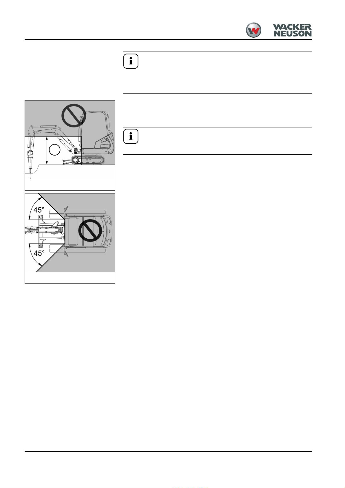
Bear in mind the following when working with the machine:
Tilting the machine in the immediate vicinity of walls or parts of buildings
carries a danger of crushing.
Danger of severe crushing of body!
☞ All persons must stay clear of the hazard zone when tilting the machine.
☞ Tilt the machine only on firm ground.
☞ Tilt the machine only if it is at a standstill and if the attachment is empty.
☞ All doors and covers must be closed when tilting the machine.
☞ Never turn, lower or set down the attachment abruptly.
☞ Do not extend or retract the boom abruptly. Otherwise there is danger of
tipping over!
☞ When working in the immediate vicinity of a wall or parts of a building, make
sure the upper carriage does not touch anything when it is tilted.
☞ On a slope, position the machine so that the upper carriage is tilted towards
the slope. Otherwise there is danger of tipping over!
28z3 - Ausgabe 1.0 * vds_28z3_en.fm 1-1
– see chapter General safety instructions
– see chapter Warning of special hazards
– see chapter Working with the excavator
Page 4

VDS lubrication points (option)
Abb. 2: VDS lubrication points
A
A
Apply grease to lubrication points A once a week.
1-2 28z3 - Ausgabe 1.0 * * vds_28z3_en.fm
Page 5

Important
Supplementary Operator’s Manual for Protective Structures for Excavators
Supplementary Operator’s Manual for Protective Structures for Excavators
Supplementary Operator’s Manual for Protective Structures for
Excavators
Edition 1.0
Language us
Article number 1000293107
Valid for machine model
803, 1403, 1404, 1503, 1703, ET18, 1903, 2003, ET20, 2203, 2404, ET24, 2503, 28Z3,
3003, 3503, 3703, 38Z3, 5002, 50Z3, 6002, 6003, 6502, 6503, 75Z3, 8002, 8003, 9503,
12002, 14504
1.1 Supplementary Operator’s Manual
This Supplementary Operator’s Manual must be added to the original Operator’s Manual of which it forms part. Read, understand and follow this Supplementary Operator’s Manual and all other manuals supplied with the machine.
Legend
Supplementary Operator’s Manual for original
Operator’s Manual
Supplementary Operator’s Manual for translation of original Operator’s Manual
Copyright – 2012 Wacker Neuson Linz GmbH, Hörsching
Printed in Michigan U.S.A.
All rights reserved, in particular the globally applicable copyright, right of reproduction and right of distribution.
No part of this publication may be reproduced, translated or used in any form or by any means – graphic, electronic or mechanical including photocopy-
ing, recording, taping or information storage or retrieval systems – without prior permission in writing from the manufacturer.
No reproduction or translation of this publication, in whole or part, without the written consent of Wacker Neuson Linz GmbH.
Violations of legal regulations, in particular of the copyright protection, will be subject to civil and criminal prosecution.
Wacker Neuson Linz GmbH keep abreast of the latest technical developments and constantly improve their products. For this reason, we may from time
to time make changes to diagrams and descriptions in this documentation which do not reflect products which have already been delivered and which will
not be implemented on these machines.
Technical data, dimensions and weights are given as an indication only. Responsibility for errors or omissions not accepted.
–
x
Wacker Neuson Linz GmbH
Flughafenstr. 7
A-4063 Hörsching
Phone +43 7221 63000
E-mail: office.linz@wackerneuson.com
www.wackerneuson.com
Edition 1.0 Supplementary Operator’s Manual for Protective Structures for Excavators 1-1
Page 6

Supplementary Operator’s Manual for Protective Structures for Excavators
Definition of the term “Protective Structure”
Protective structures are additional elements that protect the operator or user against risk.
These elements can be installed later on or as standard equipment.
Explanation of abbreviations
ROPS:
Roll Over Protective Structure
TOPS:
Tip Over Protective Structure
FOPS:
Falling Objects Protective Structure
FGPS:
Front Guard Protective Structure. Called “Front Guard” in this Supplementary Operator’s
Manual.
1-2 Edition 1.0 * Supplementary Operator’s Manual for Protective Structures for Excavators
Page 7

Supplementary Operator’s Manual for Protective Structures for Excavators
W ARNUNG
DANGER
W ARNUNG
WARNINGW
W ARNUNG
CAUTION
NOTICE
Important
1.2 Safety Symbols Found In This Manual
Important indications regarding the safety of the personnel and the machine are identified
in this Supplementary Operator’s Manual with the following terms and symbols:
DANGER indicates a hazardous situation which, if not
avoided, will result in death or serious injury.
Potential consequences of the hazard.
• Obey all safety messages that follow this symbol to avoid injury or death.
WARNING indicates a hazardous situation which, if not
avoided, could result in death or serious injury.
Potential consequences of the hazard.
• Obey all safety messages that follow this symbol to avoid possible injury or
death.
CAUTION indicates a hazardous situation which, if not
avoided, could result in minor or moderate injury.
Potential consequences of the hazard.
• Obey all safety messages that follow this symbol to avoid possible minor or
moderate injury.
NOTICE indicates a situation which, if not avoided, could result in property
damage.
Important identifies an instruction that, when followed, provides for a more efficient and economical use of the machine.
Edition 1.0 Supplementary Operator’s Manual for Protective Structures for Excavators 1-3
Page 8

Supplementary Operator’s Manual for Protective Structures for Excavators
W ARNUNG
WARNINGW
Important
Important
1.3 Mechanical integrity
Accident hazard due to modified cab and protective structures.
Incorrect work on the cab and protective structures could causes serious injury
or death.
• No drilling, cutting or grinding on the cab and protective structures.
• Welding, straightening or bending work on the cab and protective structures is
prohibited.
• Immediately have a damaged cab or protective structure replaced.
Check the cab/canopy/rollbar and all protective structures once a day for damage.
Protective structures may only be installed or removed by an authorized
Wacker Neuson Service Center.
1-4 Edition 1.0 * Supplementary Operator’s Manual for Protective Structures for Excavators
Page 9

Supplementary Operator’s Manual for Protective Structures for Excavators
Important
Important
1.4 Differentiation of protective structures
• Machine operation is only allowed with a correctly installed and intact cab,
correctly installed and intact canopy or rollbar for the 803 (option).
• For additional protection, only use correctly installed and intact Wacker Neuson
protective structures that have been released for the machine.
Rollbar (valid for 803)
The rollbar has been specially designed for protection in case of an accident.
• ROPS/TOPS tested rollbar (option).
• Shatter protection (option from AI00967); protective structure against falling objects
(fragments or splinters) projected from front of machine.
Cab/canopy (valid for 1403/1404/1503/1703/ET18/1903/2003/ET20/2203/2404/
ET24/2503/28Z3/3003/3503/3703/38Z3/50Z3)
The cab/canopy have been specially designed for protection in case of an accident.
• ROPS/TOPS tested canopy (open version).
• ROPS/TOPS tested cab (closed version/option).
• Protective FOPS structure (option) for cab/canopy; protective structure against falling
objects.
• Front Guard (option) for cab/canopy; protective structure against objects from the
front (for instance pipes, tree trunks etc.).
• Shatter protection (option) for canopy; protective structure against falling objects
(fragments or splinters) projected from front of machine.
Unless otherwise specified, the term “Cab” refers both to the open and closed
variants.
Cab (valid for 5002/6002/6003/6502/6503/75Z3/8002/8003/9503/12002/14504)
The cab has been specially designed for protection in case of an accident:
• ROPS/TOPS tested cab.
• Protective FOPS structure (option) for cab; protective structure against falling objects.
• Front Guard (option) for cab; protective structure against objects from the front (for
instance pipes, tree trunks etc.).
Not all protective structures are available for all machines, and not all protective structures
can be combined with each other. If you are not sure, contact a Wacker Neuson service
center.
Edition 1.0 Supplementary Operator’s Manual for Protective Structures for Excavators 1-5
Page 10

Supplementary Operator’s Manual for Protective Structures for Excavators
Definition of FOPS/Front Guard categories
Category I:
FOPS and Front Guard to protect against small falling objects or small objects penetrating
the cab from the front of the machine, such as bricks, small pieces of concrete, tools, for
machines that are used for repairing roads, landscaping work and for working on other
construction sites, for instance.
Category II:
FOPS or Front Guard to protect against heavy falling objects or heavy objects penetrating
the cab from the front of the machine, such as trees, pieces of rock, for machines that are
used for clearance work, demolition work and forestry work.
Responsibility for machine equipped with protective structures
The decision regarding the necessary protective structures (type and category I or II) must
be made by the machine operator and depends on the specific work situation.
The operator must observe the national regulations and he must inform the user on the
protective structure to be used in a specific work situation.
1-6 Edition 1.0 * Supplementary Operator’s Manual for Protective Structures for Excavators
Page 11

Supplementary Operator’s Manual for Protective Structures for Excavators
W ARNUNG
DANGER
Important
Important
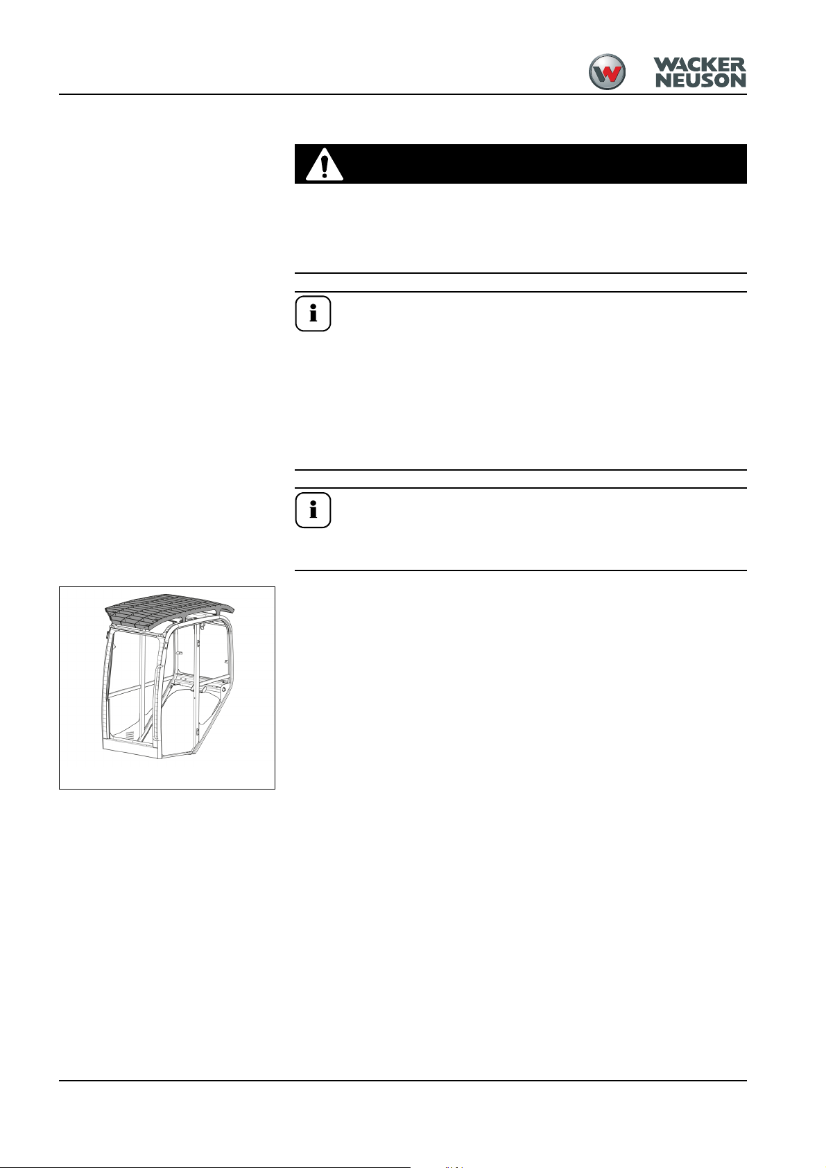
Fig. 1: FOPS category I (symbolic representation)
Protective FOPS structure/small screen – category I (option)
Crushing hazard. Falling objects.
Objects will cause severe injury or death.
• Machine operation is prohibited in areas with risks of falling objects, without a
protective FOPS structure.
The protective FOPS structure corresponds to category I according to ISO
3449:1992 (valid for 1404 from AG02423) or ISO 10262:1998 (valid for ET18/
ET20/ET24/2503/28Z3/3503/38Z3/50Z3/6003/6503/75Z3/8003/9503/14504).
• Follow all local, state, or national regulations covering falling objects.
• The operator must ensure that only work is performed that does not require any
higher protection.
• Accidents cannot be fully avoided despite equipping a machine with protective
structures.
Protective structures may only be installed or removed by an authorized
Wacker Neuson Service Center.
Edition 1.0 Supplementary Operator’s Manual for Protective Structures for Excavators 1-7
Page 12
Supplementary Operator’s Manual for Protective Structures for Excavators
W ARNUNG
DANGER
Important
Important
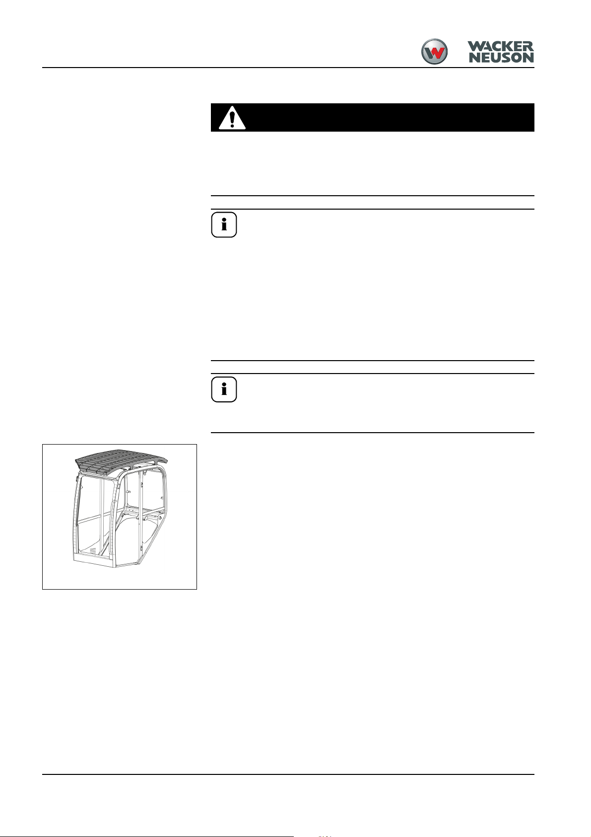
Fig. 2: FOPS category I (symbolic representation)
Protective FOPS structure/large screen – category I (option)
Crushing hazard. Falling objects.
Objects will cause severe injury or death.
• Machine operation is prohibited in areas with risks of falling objects, without a
protective FOPS structure.
The protective FOPS structure corresponds to category I according to ISO
3449:1992 (valid for 38Z3) or according to ISO 3449:2008 (valid for 28Z3).
• Follow all local, state, or national regulations covering falling objects.
• The operator must ensure that only work is performed that does not require any
higher protection.
• Accidencts cannot be fully avoided despite equipping a machine with protective
structures.
Protective structures may only be installed or removed by an authorized
Wacker Neuson Service Center.
1-8 Edition 1.0 * Supplementary Operator’s Manual for Protective Structures for Excavators
Page 13

Supplementary Operator’s Manual for Protective Structures for Excavators
W ARNUNG
DANGER
Important
Important
Fig. 3: FOPS category I (symbolic representation)
Protective FOPS structure/canopy – category I (option)
Crushing hazard. Falling objects.
Objects will cause severe injury or death.
• Machine operation is prohibited in areas with risks of falling objects, without a
protective FOPS structure.
The protective FOPS structure corresponds to category I according to ISO
3449:1992 (valid for 1403/1503/1703 (up to AF05530)/1903/2003 (up to
AF05530)/2203/2503/3003/3503/3703/5002/6002/6502).
• Follow all local, state, or national regulations covering falling objects.
• The operator must ensure that only work is performed that does not require any
higher protection.
• Accidencts cannot be fully avoided despite equipping a machine with protective
structures.
Protective structures may only be installed or removed by an authorized
Wacker Neuson Service Center.
Edition 1.0 Supplementary Operator’s Manual for Protective Structures for Excavators 1-9
Page 14
Supplementary Operator’s Manual for Protective Structures for Excavators
W ARNUNG
DANGER
Important
Important
Fig. 4: FOPS category II (symbolic representation)
Protective FOPS structure/large screen – category II (option)
Crushing hazard. Falling objects.
Objects will cause severe injury or death.
• Machine operation is prohibited in areas with risks of falling objects, without a
protective FOPS structure.
The protective FOPS structure corresponds to category II according to ISO
3449:1992 (valid for 1404/1703 (from AG02503)/2003 (from AG02503)/2404/
50Z3/6003/6503/75Z3/8002/8003/9503/12002) or according to ISO 3449:2005
(valid for 14504).
• Follow all local, state, or national regulations covering falling objects.
• The operator must ensure that only work is performed that does not require any
higher protection.
• Accidencts cannot be fully avoided despite equipping a machine with protective
structures.
Protective structures may only be installed or removed by an authorized
Wacker Neuson Service Center.
1-10 Edition 1.0 * Supplementary Operator’s Manual for Protective Structures for Excavators
Page 15

Supplementary Operator’s Manual for Protective Structures for Excavators
W ARNUNG
DANGER
Important
Important
Fig. 5: Front Guard with integrated FOPS
(symbolic representation)
Protective Front Guard structure with integrated FOPS/category I respectively (option)
Stabbing/puncture/crushing hazard from falling objects
(fragments or splinters) projected from front of machine.
Objects will cause severe injury or death.
• Machine operation is prohibited in areas with risks of objects penetrating the
cab from the front of the machine, for instance pipes, tree trunks etc. and of
falling objects, without a protective Front Guard structure with an integrated
FOPS.
The protective Front Guard structure with integrated FOPS corresponds to category I according to ISO 10262:1998 (valid for ET18/ET20/ET24).
• Follow all local, state, or national regulations covering falling objects.
• The operator must ensure that only work is performed that does not require any
higher protection.
• Accidencts cannot be fully avoided despite equipping a machine with protective
structures.
Protective structures may only be installed or removed by an authorized
Wacker Neuson Service Center.
Edition 1.0 Supplementary Operator’s Manual for Protective Structures for Excavators 1-11
Page 16
Supplementary Operator’s Manual for Protective Structures for Excavators
W ARNUNG
DANGER
Important
Important
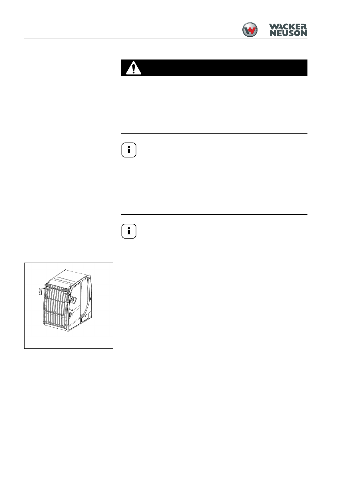
Fig. 6: Protective Front Guard structure (symbolic repre-
sentation)
Protective Front Guard structure category I (option)
Stabbing/puncture/crushing hazard from falling objects
(fragments or splinters) projected from front of machine.
Objects will cause severe injury or death.
• Machine operation is prohibited in areas with risks of objects penetrating the
cab from the front of the machine, for instance pipes, tree trunks etc. and of
falling objects, without a protective Front Guard structure with an integrated
FOPS.
The protective Front Guard structure corresponds to category I according to
ISO 10262:1998 (valid for 2503/28Z3/3003/3503/3703/38Z3).
• Follow all local, state, or national regulations covering falling objects.
• The operator must ensure that only work is performed that does not require any
higher protection.
• Accidencts cannot be fully avoided despite equipping a machine with protective
structures.
Protective structures may only be installed or removed by an authorized
Wacker Neuson Service Center.
1-12 Edition 1.0 * Supplementary Operator’s Manual for Protective Structures for Excavators
Page 17

Supplementary Operator’s Manual for Protective Structures for Excavators
W ARNUNG
DANGER
Important
Important
Fig. 7: Protective Front Guard structure (symbolic repre-
sentation)
Protective Front Guard structure category II (option)
Stabbing/puncture/crushing hazard from falling objects
(fragments or splinters) projected from front of machine.
Objects will cause severe injury or death.
• Machine operation is prohibited in areas with risks of objects penetrating the
cab from the front of the machine, for instance pipes, tree trunks etc. and of
falling objects, without a protective Front Guard structure with an integrated
FOPS.
The protective Front Guard structure corresponds to category II according to
ISO 10262:1998 (valid for 50Z3/6003/6503/75Z3/8002/8003/9503/12002/
14504).
• Follow all local, state, or national regulations covering falling objects.
• The operator must ensure that only work is performed that does not require any
higher protection.
• Accidencts cannot be fully avoided despite equipping a machine with protective
structures.
Protective structures may only be installed or removed by an authorized
Wacker Neuson Service Center.
Edition 1.0 Supplementary Operator’s Manual for Protective Structures for Excavators 1-13
Page 18
Supplementary Operator’s Manual for Protective Structures for Excavators
W ARNUNG
WARNINGW
W ARNUNG
WARNINGW
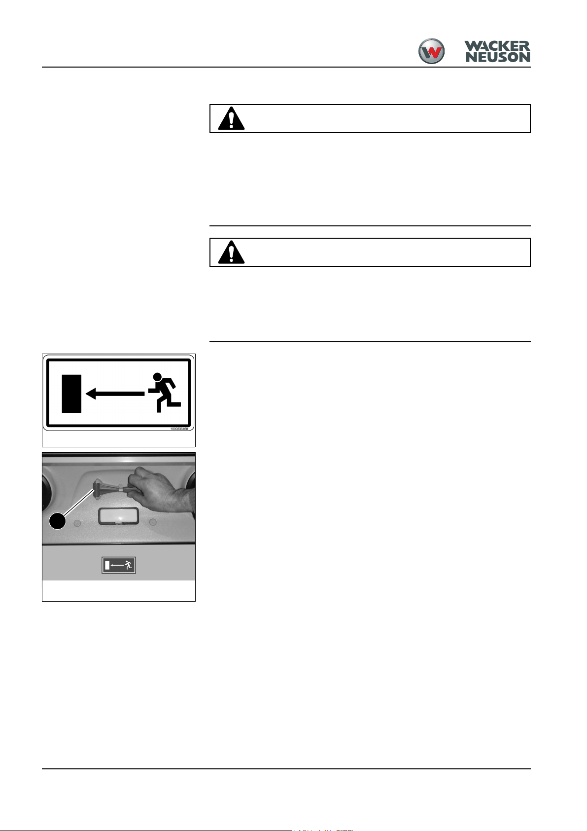
Fig. 8: Emergency exit label
Fig. 9: Position of emergency hammer (symbolic repre-
sentation)
A
Emergency exit for cab equipped with protective Front Guard structure
Cutting Hazard. Risk of injury due to broken glass.
Risk of personal injury.
• Only smash windows in an absolute emergency.
• Protect face and eyes sufficiently from glass splinters before breaking a window pane.
• Remove all broken glass from the window frame before exiting the cab.
Tripping/Slipping/Falling hazard. Use the rear window as an
exit only in an emergency.
Risk of personal injury.The machine has no footholds or handles at the rear for
a safe exit. Therefore injuries may arise when exiting in an emergency.
• Exit the machine through the rear window only in an absolute emergency.
Meaning (option)
This label identifies the emergency exit for a cab equipped with protective Front Guard
structure.
Position
Inside the cab, above the rear window
The rear window can be used as an exit if the door is blocked.
Smash the rear window with emergency hammer A.
1-14 Edition 1.0 * Supplementary Operator’s Manual for Protective Structures for Excavators
Page 19

Supplementary Operator’s Manual for Protective Structures for Excavators
W ARNUNG
DANGER
W ARNUNG
WARNINGW
Important
Important
Important
Shatter protection (option)
Stabbing/puncture/crushing hazard from falling objects
(fragments or splinters) projected from front of machine.
Objects will cause severe injury or death.
• A shatter protection must be installed on a canopy version if an attachment (a
hammer, for instance) causes fragments to fly. This shatter protection takes
over the function of a front window.
• Pay attention to the restricted work range (see fig. 13 and 14).
• For 803 machines up to serial number AI00966, operation with an attachment
causing fragments to fly is absolutely prohibited.
Accident hazard in conditions of restricted visibility due to
rain, snowfall, dust etc..
Could causes severe injury or death.
• Stop work immediately.
The shatter protection (canopy option) protects the driver against fragments
from the front.
• Follow all local, state, or national regulations covering falling objects.
• The operator must ensure that only work is performed that does not require any
higher protection.
• Accidents cannot be fully avoided despite equipping a machine with protective
structures.
Do not use brushes, steel wool or other abrasive cleaners for cleaning the
polycarbonate disc. Do not wipe dust in a dry state.
Protective structures may only be installed or removed by an authorized
Wacker Neuson Service Center.
Edition 1.0 Supplementary Operator’s Manual for Protective Structures for Excavators 1-15
Page 20
Supplementary Operator’s Manual for Protective Structures for Excavators
Important
Important
Fig. 10: Work area with shatter protection
A
Fig. 11: Work area with shatter protection (top
view)
A shatter protection must be installed on a canopy version if an attachment (a
hammer, for instance) causes fragments to fly. Pay attention to the restricted
work range (see fig. 13 and 14).
Work area with shatter protection
Height of work area A: 120 cm (47 in).
Figures 13 and 14 refer to work with a Wacker Neuson hydraulic hammer.
Working with another attachment can modify the height of the work area.
1-16 Edition 1.0 * Supplementary Operator’s Manual for Protective Structures for Excavators
Page 21

Table of Contents
Table of Contents
Table of Contents
I
Introduction
Important operator information ................................................................................ 1-1
Machine overview .................................................................................................... 1-2
Brief description ....................................................................................................... 1-3
Travelling drive .................................................................................................. 1-3
Work hydraulics ................................................................................................. 1-3
Cooling system .................................................................................................. 1-3
Cab .................................................................................................................... 1-3
Fields of application, attachments ........................................................................... 1-4
Use: attachment ................................................................................................ 1-4
Operator Qualifications ............................................................................................ 1-5
EC Declaration of Conformity for machines delivered before the 29th December 2009
1-6
EC Declaration of Conformity for machines delivered after the 29th December 2009 ..
1-7
Declaration of Conformity for machines without the CE mark at the type plate ....... 1-8
Type labels and component numbers ...................................................................... 1-9
Symbols (up to AG01685) ..................................................................................... 1-11
...on the outside of the machine ...................................................................... 1-11
Symbols (from AG01686) ...................................................................................... 1-15
Symbols ........................................................................................................... 1-16
Safety labels .................................................................................................... 1-18
Fire extinguisher .................................................................................................... 1-23
Safety Information
Safety Symbols Found in this Manual ..................................................................... 2-1
Warranty .................................................................................................................. 2-2
Designated Use ....................................................................................................... 2-2
Preparing to use the machine .................................................................................. 2-2
Conditions for use .............................................................................................. 2-2
User training and knowledge ............................................................................. 2-3
Modifications and spare parts ............................................................................ 2-3
Applications with lifting gear .............................................................................. 2-3
Operator and Technician Qualifications and Basic Responsibilities ........................ 2-5
User/owner responsibility .................................................................................. 2-5
Repair person qualifications .............................................................................. 2-5
Safety instructions Regarding Operation ................................................................. 2-5
Preparing for use ............................................................................................... 2-5
Starting and stopping ......................................................................................... 2-6
Work area awareness ........................................................................................ 2-6
Danger area awareness .................................................................................... 2-6
Carrying passengers ......................................................................................... 2-7
Mechanical integrity ........................................................................................... 2-7
Traveling ............................................................................................................ 2-7
Applications with Lifting Gear .................................................................................. 2-8
General information ........................................................................................... 2-8
Safety criteria ..................................................................................................... 2-8
Conditions for safe operation ............................................................................. 2-8
Attachments ............................................................................................................. 2-8
General information regarding attachments ...................................................... 2-8
Installation notes ................................................................................................ 2-9
Transport and Towing .............................................................................................. 2-9
Towing ............................................................................................................... 2-9
Transporting ...................................................................................................... 2-9
OM 28Z3 US - Edition 2.0 * Ba28Z3us2_0IVZ.fm I-1
Page 22

Table of Contents
Safety Guidelines for Maintenance .......................................................................... 2-9
General maintenance notes ............................................................................... 2-9
Personal safety measures ............................................................................... 2-10
Preparing for maintenance and repair work ..................................................... 2-10
Performing maintenance and repairs ............................................................... 2-10
Special Hazards ..................................................................................................... 2-11
Battery ............................................................................................................. 2-11
Tracks .............................................................................................................. 2-12
Electric energy ................................................................................................. 2-12
Hydraulics ........................................................................................................ 2-12
Noise ................................................................................................................ 2-12
MSDS .............................................................................................................. 2-13
Gas, dust, steam, smoke ................................................................................. 2-13
Safety Guidelines while using Internal Combustion Engines ................................. 2-13
Running the engine .......................................................................................... 2-13
Fueling the engine ........................................................................................... 2-13
Operation
Cab overview ........................................................................................................... 3-3
Instrument panel overview ....................................................................................... 3-5
Operating the excavator ........................................................................................... 3-6
Putting the machine into operation for the first time .......................................... 3-6
Running-in period .............................................................................................. 3-6
Check lists ......................................................................................................... 3-7
Start-up checklist ............................................................................................... 3-7
Operation checklist ............................................................................................ 3-8
Parking checklist ................................................................................................ 3-8
Operating the excavator ........................................................................................... 3-9
Preheating / start switch: overview .................................................................... 3-9
Throttle lever: overview ...................................................................................... 3-9
Indicator lights and warning lights: overview ................................................... 3-10
Before starting the engine ................................................................................ 3-12
Starting the engine: general ............................................................................. 3-12
Procedure ........................................................................................................ 3-12
Starting with the drive interlock (option) ........................................................... 3-13
Starting at low temperatures ............................................................................ 3-13
When the engine has started ... ....................................................................... 3-14
Engine warm-up ............................................................................................... 3-14
Jump-starting the engine (supply battery) ....................................................... 3-14
Safety instructions ........................................................................................... 3-14
Special instructions for operating on public roads ........................................... 3-16
Traveling operation .......................................................................................... 3-16
Drive levers ...................................................................................................... 3-16
High speed ....................................................................................................... 3-17
Hydraulic brake ................................................................................................ 3-17
Mechanical brake ............................................................................................. 3-17
Operating on slopes ............................................................................................... 3-18
Specific safety instructions .............................................................................. 3-18
Operating on slopes ......................................................................................... 3-19
Stabilizer blade operation ................................................................................ 3-20
Stopping and parking the machine ........................................................................ 3-21
Stop the machine ............................................................................................. 3-21
Parking the machine on slopes ........................................................................ 3-22
Light system ........................................................................................................... 3-23
Roof lights (option) ........................................................................................... 3-23
Interior light ...................................................................................................... 3-24
Rotating beacon (option) ................................................................................. 3-24
I-2 OM 28Z3 US - Edition 2.0 * * Ba28Z3us2_0IVZ.fm
Page 23

Table of Contents
Cab heating and ventilation ................................................................................... 3-24
Heating adjustment .......................................................................................... 3-25
Washer system ...................................................................................................... 3-25
Tank for washer system .................................................................................. 3-26
Seat ....................................................................................................................... 3-26
Seat adjustment ............................................................................................... 3-26
Weight adjustment ........................................................................................... 3-27
Horizontal adjustment ...................................................................................... 3-27
Seat belt ................................................................................................................. 3-28
Emergency exit ...................................................................................................... 3-29
Front window ......................................................................................................... 3-30
Door ....................................................................................................................... 3-31
Side window ........................................................................................................... 3-32
Engine cover .......................................................................................................... 3-32
Exit through the door ............................................................................................. 3-33
Armrest adjustment ................................................................................................ 3-34
Towing the track excavator .................................................................................... 3-34
Towing ............................................................................................................. 3-34
Lifting excavator ..................................................................................................... 3-36
Loading and transporting the machine .................................................................. 3-37
Tying down the excavator ...................................................................................... 3-38
Operating the machine .......................................................................................... 3-39
General safety instructions .............................................................................. 3-39
Control levers/control pattern ’’A’’: overview .......................................................... 3-40
Left-hand side control lever ............................................................................. 3-40
Boom swivel controls ....................................................................................... 3-40
Auxiliary hydraulics .......................................................................................... 3-41
Right-hand side control lever ........................................................................... 3-41
Lowering the boom with the engine stopped ................................................... 3-42
Releasing pressure .......................................................................................... 3-42
Rotating the upper carriage ............................................................................. 3-42
Swivel unit brake ............................................................................................. 3-43
Changeover valve for control pattern’’B’’(option) ................................................... 3-44
Left-hand side control lever ............................................................................. 3-44
Right-hand side control lever ........................................................................... 3-44
Directional valve position ................................................................................. 3-44
Directional valve .............................................................................................. 3-45
Control lever with proportional controls (option): overview .................................... 3-46
Function ........................................................................................................... 3-46
Measures to be taken in case of malfunctions ................................................ 3-47
Left-hand side control lever ............................................................................. 3-47
Boom swivel controls ....................................................................................... 3-48
Auxiliary hydraulics .......................................................................................... 3-48
Hammer operation ........................................................................................... 3-48
Adjusting control response: ............................................................................. 3-49
Characteristic curves – status display ............................................................. 3-49
Lowering the boom with the engine switched off ............................................. 3-50
Releasing pressure .......................................................................................... 3-50
Rotating the upper carriage ............................................................................. 3-51
Rotating upper carriage brake ......................................................................... 3-51
Control lever if equipped with 3rd control circuit (option): overview ....................... 3-52
Left-hand side control lever ............................................................................. 3-52
Boom swivel controls ....................................................................................... 3-52
Auxiliary hydraulics .......................................................................................... 3-53
Right-hand side control lever ........................................................................... 3-53
Lowering the boom with the engine switched off ............................................. 3-54
Releasing pressure .......................................................................................... 3-54
OM 28Z3 US - Edition 2.0 * Ba28Z3us2_0IVZ.fm I-3
Page 24

Table of Contents
Rotating the upper carriage ............................................................................. 3-54
Rotating upper carriage ................................................................................... 3-55
Releasing the pressure on the work hydraulics ..................................................... 3-56
Releasing pressure .......................................................................................... 3-56
Pressure release with proportional controls (option) ....................................... 3-56
Coupling and uncoupling attachments ................................................................... 3-57
Specific safety instructions .............................................................................. 3-57
Removing a bucket .......................................................................................... 3-58
Mounting a bucket ........................................................................................... 3-58
Quickhitch (option) ................................................................................................. 3-59
Hydraulic quickhitch (option) .................................................................................. 3-60
Maintenance .................................................................................................... 3-60
Operation ......................................................................................................... 3-61
Powertilt (option) .................................................................................................... 3-63
Re-equipping ................................................................................................... 3-64
Mounting the Powertilt unit .............................................................................. 3-64
Removing the Powertilt unit ............................................................................. 3-64
Port .................................................................................................................. 3-65
Operation ......................................................................................................... 3-65
Right-hand side control lever (Powertilt) .......................................................... 3-66
Connections for auxiliary hydraulics ...................................................................... 3-67
Grab couplings ................................................................................................. 3-67
Attachments ........................................................................................................... 3-68
Load holding control valve (option) ........................................................................ 3-68
Working with the excavator .................................................................................... 3-69
Working with the standard bucket .................................................................... 3-69
Prohibited operation ......................................................................................... 3-69
Excavator work position ................................................................................... 3-71
Bucket position when digging .......................................................................... 3-71
Excavating trenches ........................................................................................ 3-71
Loading ............................................................................................................ 3-72
Grading ............................................................................................................ 3-72
Excavating trenches sideways ......................................................................... 3-72
Working alongside trenches ............................................................................ 3-73
Stabilizer blade at rear ..................................................................................... 3-73
Grading .................................................................................................................. 3-75
Grading ............................................................................................................ 3-75
Safe load indicator (option) .................................................................................... 3-75
Troubleshooting
Engine trouble ......................................................................................................... 4-2
Malfunctions of the Powertilt unit ............................................................................. 4-3
Maintenance
Introduction .............................................................................................................. 5-1
Fuel system .............................................................................................................. 5-2
Specific safety instructions ................................................................................ 5-2
Refueling ............................................................................................................ 5-2
Draining the fuel ................................................................................................. 5-3
Stationary fuel pumps ........................................................................................ 5-3
Diesel fuel specification ..................................................................................... 5-4
Bleeding the fuel system .................................................................................... 5-4
Water separator ................................................................................................. 5-5
Engine lubrication system ........................................................................................ 5-6
Checking the oil level ......................................................................................... 5-6
Adding engine oil ............................................................................................... 5-7
Engine and hydraulics cooling system ..................................................................... 5-8
Checking / filling up coolant ............................................................................... 5-8
I-4 OM 28Z3 US - Edition 2.0 * * Ba28Z3us2_0IVZ.fm
Page 25

Table of Contents
Specific safety instructions ................................................................................ 5-9
Draining coolant ............................................................................................... 5-11
Air filter ................................................................................................................... 5-12
Replacing the filter ........................................................................................... 5-12
V-belt ..................................................................................................................... 5-14
Checking V-belt tension ................................................................................... 5-14
Retightening the V-belt .................................................................................... 5-15
Hydraulic system ................................................................................................... 5-16
Specific safety instructions .............................................................................. 5-16
Checking the hydraulic oil level ....................................................................... 5-17
Adding hydraulic oil ......................................................................................... 5-18
Important information for the use of biodegradable oil .................................... 5-19
Pilot valve .............................................................................................................. 5-20
Checking hydraulic pressure lines ................................................................... 5-21
Tracks .................................................................................................................... 5-23
Checking track tension .................................................................................... 5-23
Adjusting the track tension .............................................................................. 5-24
Track propulsion final drive .................................................................................... 5-25
Checking the oil level and filling up oil ............................................................. 5-25
Draining oil ....................................................................................................... 5-25
Maintenance of attachments ........................................................................... 5-26
Powertilt (option) .............................................................................................. 5-26
Electric system ....................................................................................................... 5-27
Specific safety instructions .............................................................................. 5-27
Service and maintenance work at regular intervals ......................................... 5-27
Instructions concerning specific components .................................................. 5-28
Alternator ......................................................................................................... 5-28
Battery ............................................................................................................. 5-29
General maintenance work .................................................................................... 5-30
Cleaning .......................................................................................................... 5-30
General instructions for all areas of the machine ............................................ 5-30
Inside the cab .................................................................................................. 5-31
Exterior of the machine .................................................................................... 5-31
Engine compartment ....................................................................................... 5-31
Threaded connections and fasteners .............................................................. 5-32
Pivots and hinges ............................................................................................ 5-32
Maintenance if the machine is out of service for a longer period of time ............... 5-33
Preparatory work before taking the machine out of service ............................ 5-33
Putting the machine into operation again ........................................................ 5-33
Fluids and lubricants ............................................................................................. 5-34
Additional oil change and filter replacement (hydraulics) ................................ 5-35
Maintenance plan (overview) ................................................................................. 5-35
Maintenance label .................................................................................................. 5-40
Explanation of symbols on the maintenance label .......................................... 5-40
Specifications
Chassis .................................................................................................................... 6-1
Engine ...................................................................................................................... 6-1
Hydraulic system ..................................................................................................... 6-1
Undercarriage and swivel unit ................................................................................. 6-2
Stabilizer blade ........................................................................................................ 6-2
Work hydraulics ....................................................................................................... 6-2
Electric system ......................................................................................................... 6-3
Fuse box in engine compartment ...................................................................... 6-3
OM 28Z3 US - Edition 2.0 * Ba28Z3us2_0IVZ.fm I-5
Page 26

Table of Contents
Noise levels .............................................................................................................. 6-4
Vibration ................................................................................................................... 6-4
Coolant compound table .......................................................................................... 6-4
Powertilt ................................................................................................................... 6-4
Dimensions model 28Z3 .......................................................................................... 6-5
Lift capacity table 28Z3 ............................................................................................ 6-6
Lift capacity table 28Z3, long stick option ................................................................ 6-7
Lift capacity table 28Z3, extra weight option ............................................................ 6-8
Lift capacity table 28Z3, long stick and extra weight options ................................... 6-9
I-6 OM 28Z3 US - Edition 2.0 * * Ba28Z3us2_0IVZ.fm
Page 27

Index
I
Index
Symbole
“Hose burst valve” safety feature (option) ............................................3-68
A
Abbreviations .........................................................................................1-1
Air filter .................................................................................................5-12
B
Biodegradable oil .................................................................................5-19
C
Check lists .............................................................................................3-7
Crane-handling bracket ....................................................................... 3-36
D
Driving on public roads ........................................................................3-16
Driving the excavator .............................................................................3-9
F
Fire extinguisher ..................................................................................1-23
Fluids and lubricants ............................................................................5-34
H
Heating ................................................................................................3-24
Hose burst valve (option) .....................................................................3-68
I
Important information
On this Operator’s Manual ..............................................................1-1
Indicator lights and warning lights ........................................................3-10
Instrument panel overview .....................................................................3-5
Interior light ..........................................................................................3-24
L
Legal regulations ...................................................................................1-5
Light system .........................................................................................3-23
Lowering the boom with the engine switched off .............. 3-42, 3-50, 3-54
M
Machine
Brief description .............................................................................. 1-3
Fields of application ........................................................................ 1-4
Loading and transporting .............................................................. 3-37
Overview ........................................................................................ 1-2
Maintenance
Air filter ......................................................................................... 5-12
Biodegradable oil .......................................................................... 5-19
Bleeding the fuel system ................................................................ 5-4
Checking the coolant level ............................................................. 5-9
Checking the engine oil level .......................................................... 5-6
Checking the hydraulic oil level .................................................... 5-17
Cleaning ....................................................................................... 5-30
Electric system ............................................................................. 5-27
Engine and hydraulics cooling system ........................................... 5-8
Engine lubrication system .............................................................. 5-6
Filling up coolant ............................................................................ 5-9
Fluids and lubricants .................................................................... 5-34
Fuel system .................................................................................... 5-2
General maintenance work .......................................................... 5-30
Hydraulic pressure lines ............................................................... 5-21
Hydraulic system .......................................................................... 5-16
Instructions concerning specific components ............................... 5-28
Maintenance plan ......................................................................... 5-35
Pivots and hinges ......................................................................... 5-32
Screw connections ....................................................................... 5-32
Service and maintenance work at regular intervals ...................... 5-27
Track maintenance ....................................................................... 5-23
V-belt ............................................................................................ 5-14
N
Noise levels ................................................................................ 1-11, 1-16
O
Operation .............................................................................................. 3-1
Before starting the engine ............................................................ 3-12
Cab overview .................................................................................. 3-3
Hose burst valve (option) ............................................................. 3-68
Instrument panel overview ............................................................. 3-5
Moving off ..................................................................................... 3-16
Parking the machine ..................................................................... 3-21
Seat belt height adjustment .......................................................... 3-28
Starting the engine ....................................................................... 3-12
Triple articulation boom (option) .................................3-40, 3-48, 3-52
P
Powertilt
Maintenance ................................................................................. 3-65
Preheating start switch .......................................................................... 3-9
Putting into operation ............................................................................ 3-2
Check lists ...................................................................................... 3-7
Putting the machine into operation for the first time ....................... 3-6
Safety instructions .......................................................................... 3-6
R
Refuelling .............................................................................................. 5-2
Rotating beacon .................................................................................. 3-24
Running-in period .................................................................................. 3-6
OM 28Z3 US - Edition 2.0 * Ba28Z3us2_0SIX.fm I-7
Page 28

Index
S
Seat adjustment
Backrest adjustment .....................................................................3-27
Horizontal adjustment ...................................................................3-27
Weight adjustment ........................................................................3-27
Seat belt ...............................................................................................3-28
Seat belt height adjustment .................................................................3-28
Signs and symbols ...............................................................................1-11
Specifications .........................................................................................6-1
Chassis ...........................................................................................6-1
Coolant compound table .................................................................6-4
Dimensions .....................................................................................6-5
Electric system ................................................................................6-3
Engine .............................................................................................6-1
Noise levels ....................................................................................6-4
Vibration ..........................................................................................6-4
Work hydraulics ..............................................................................6-2
Starting aid ...........................................................................................3-14
T
Track maintenance ..............................................................................5-23
V
Ventilation ............................................................................................3-24
Ventilation, fresh air ......................................................................3-24
W
Washer system ....................................................................................3-25
Tank ..............................................................................................3-26
Working
Freeing the machine .....................................................................3-74
Practical hints ...............................................................................3-74
I-8 OM 28Z3 US - Edition 2.0 * * Ba28Z3us2_0SIX.fm
Page 29

1 Introduction
1.1 Important operator information
Store the Operator's Manual in the storage compartment at the rear of the seat.
This Operator's Manual contains important information on how to work safely, correctly
and economically with the machine. It provides information and instruction for all operators
regardless of experience. It helps to avoid dangerous situations and reduce repair costs
and downtimes. Furthermore, the reliability and the service life of the machine will be
increased by following the instructions in the Operator's Manual. This is why the Operator's
Manual must always be kept at hand in the machine.
Your own safety, as well as the safety of others, depends to a great extent on how the
machine is moved and operated. Thoroughly read and understand the information in this
Operator's Manual before operating the machine for the first time. This Operator's Manual
will help to familiarize yourself more easily with the machine, thereby enabling you to use it
more safely and efficiently.
Before operating this machine for the first time, carefully read the section "Safety Instructions" to learn how to operate the machine safely. As a rule, keep the following in mind:
Careful and prudent working is the best way to avoid accidents!
Special Instructions
• Instructions are provided for bucket attachments. No instructions are provided for other
attachments. Refer to the specific attachment operator's manual for safe operation.
• Wacker Neuson reserves the right to make product improvement changes during the
course of series production of this machine.
• Modifying the manufacturer specification and configuration of this machine, or using
unapproved attachments, can cause personal hazards and damage the machine.
Contact your Wacker Neuson dealer for additional information and clarification
regarding modifications.
Operational safety and readiness of the machine do not only depend on your skill, but also
on maintenance and servicing of the machine. This is why regular maintenance and service work is absolutely necessary. Extensive maintenance and repair work must always be
performed by an expert with appropriate training. Insist on using original spare parts when
performing maintenance and repair work. This ensures operational safety and readiness of
your machine, and maintains its value.
• Special equipment and superstructures are not described in this Operator's Manual.
• We reserve the right to improve the technical standard of our machines.
• Modifying Wacker Neuson products and fitting them with additional equipment and
tools not included in our delivery program requires Wacker Neuson's written authorization, otherwise warranty and product liability for possible damage caused by these
modifications shall not be applicable.
Your Wacker Neuson dealer will be pleased to answer any further questions regarding the
machine or the Operator's Manual.
Abbreviations/symbols
Introduction
• This symbol stands for a list.
• Subdivision within lists or an activity. Follow the steps in the recommended
sequence.
☞ This symbol requires you to perform the activity described.
➥ Description of the effects or results of an activity.
n. s. = not shown
“Opt” = option
Stated whenever controls or other components of the machine are installed as an option.
This symbol shows the driving direction – for better orientation in figures and
graphics.
OM 28Z3 US – Edition 2.0 * 28Z3b110.fm 1-1
Page 30
Introduction
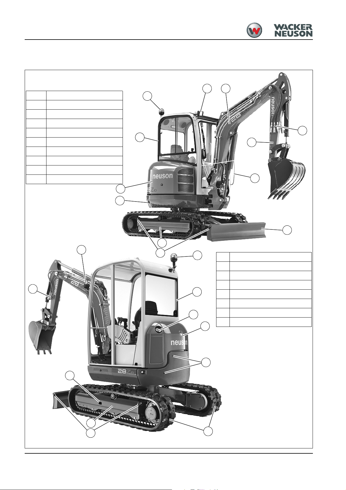
1.2 Machine overview
1 Working lights
2 Boom light
3 Boom
4Stick
5 Rubber tracks
6 Undercarriage
7 Stabilizer blade
8Cab
9 Engine cover
10 Handle
17
1
3
16
17
8
4
10
9
13
7
6
2
14
11
16
8
11 Fuel filler inlet
12 Counterweight pre-installation
13 Exhaust pipe
14 Lifting and tie down point
15 Lubrication point for track tension
16 Rotating beacon
17 Auxiliary hydraulics
18 Valve cover
18
13
12
15
6
14
Fig. 1: Machine outside views
5
1-2 OM 28Z3 US – Edition 2.0 * * 28Z3b110.fm
Page 31

1.3 Brief description
Travelling drive
Work hydraulics
Introduction
The model 28Z3 excavator is a self-propelled work machine.
Get informed on and follow the legal regulations of your country.
This machine is a versatile and powerful tool for moving earth, gravel and debris on construction sites and elsewhere. A wide range of attachments accounts for the numerous
applications of the machine, among others hammer and grab applications. See chapter
1.4 Fields of application, attachments for further applications.
The main components of the machine are:
• FOPS (Falling Object Protective Structure), TOPS (Tip Over Protective Structure) and
ROPS (Roll Over Protective Structure) tested closed cab (standard)
• FOPS (Falling Object Protective Structure), TOPS (Tip Over Protective Structure) and
ROPS (Roll Over Protective Structure) open version (option)
• Model 28Z3: water-cooled Yanmar three cylinder diesel engine.
• Sturdy steel sheet chassis; rubber-mounted engine
The diesel engine permanently drives the twin axial variable displacement pump whose oil
flow is sent to a hydraulic motor for each track drive unit.
The diesel engine also drives the joint gear pump for the work hydraulics. The oil flow of
this pump depends on the diesel engine speed only.
Cooling system
Cab
Coolant temperature is monitored with the indicator light on the machine's instrument
panel.
Do not modify or attempt to repair the ROPS cab or ROPS structure. A bent or damaged
ROPS will no longer protect the operator in the event of a tipping incident and must be
replaced. Contact your Wacker Neuson dealer for instructions or clarification.
The ROPS is a special safety device designed and produced to exacting material and
assembly standards for certification. Bending, heating, welding, cutting, or drilling holes in
the ROPS will reduce the protection performance in a tipping incident.
Fasten your seatbelt, otherwise you can be thrown around or even outside the cab and
crushed. Therefore always fasten your seatbelt as you drive and work with the machine.
Tighten the seatbelt before operating machine.
OM 28Z3 US – Edition 2.0 * 28Z3b110.fm 1-3
Page 32

Introduction
1.4 Fields of application, attachments
The attachments installed determine the intended use of this machine.
NOTICE
In order to avoid damage to the machine, only the attachments listed below
have been certified for installation on the machine.
• Contact your Wacker Neuson dealer if you wish to use other attachments.
Caution!
Personal injury or equipment damage hazards. Using other manufactures’
attachments, or attachments not designed for this excavator, can greatly
reduce the machine’s stability and output. Unapproved attachments may
damage the machine or injure the operator or those in the surrounding area.
• Only use attachments that have been approved by Wacker Neuson.
Always compare the weight of the tool and its maximum payload with the indications in the
lift capacity table. Never exceed the maximum payload stated in the lift capacity table.
Consult your Wacker Neuson dealer for assistance.
Use: attachment
Possible attachments
Description of attachment
Capacity Item no.: Excavator
Complete quickhitch - 1000018479 28Z3
3
50 l (1.8 ft
1000093755 28Z3
)
Bucket B = 300 mm (11.8’’)
3
1000017130 28Z3 For quickhitch
50 l (1.8 ft
69 l (2.4 ft
)
3
1000093756 28Z3
)
Bucket B = 400 mm (1’4’’)
3
69 l (2.4 ft
88 l (3.1 ft
1000017125 28Z3 For quickhitch
)
3
1000093757 28Z3
)
Bucket B = 500 mm (1’8’’)
3
88 l (3.1 ft
107 l (3.8 ft
1000017127 28Z3 For quickhitch
)
3
1000093758
)
28Z3
Bucket B = 600 mm (2’)
107 l (3.8 ft
127 l (4.5 ft
1000017134
)
3
1000093759 28Z3
)
28Z3 For quickhitch
3
Bucket B = 700 mm (2’4’’)
3
127 l (4.5 ft
1000017128 28Z3 For quickhitch
)
Remarks
Required for operation of Wacker Neuson quickhitch systems
3
1000096567 28Z3
111 l (3.9 ft
)
Offset bucket B = 1000 mm (3’4’’) short stick
3
111 l (3.9 ft
1000017131 28Z3 For quickhitch
)
1-4 OM 28Z3 US – Edition 2.0 * * 28Z3b110.fm
Page 33

Introduction
Description of attachment
Capacity Item no.: Excavator
3
158 l (5.6 ft
1000096568 28Z3
)
Offset bucket B = 1400 mm (4’7’’) short stick
3
158 l (5.6 ft
111 l (3.9 ft
1000017132 28Z3 For quickhitch
)
3
1000096569 28Z3
)
Offset bucket B = 1000 mm (3’4’’) long stick
3
111 l (3.9 ft
158 l (5.6 ft
1000096571 28Z3 For quickhitch
)
3
1000096570 28Z3
)
Offset bucket B = 1400 mm (4’7’’) long stick
3
158 l (5.6 ft
117 l (4.1 ft
1000096572 28Z3 For quickhitch
)
3
1000096563 28Z3
)
Ditch cleaning bucket B = 1000 mm (3’4’’)
3
116 l (4.1 ft
166 l (5.9 ft
1000096549 28Z3 For quickhitch
)
3
1000096564 28Z3
)
Ditch cleaning bucket B = 1400 mm (4’7’’)
3
164 l (5.9 ft
1000096550 28Z3 For quickhitch
)
Hammer mount console - 1000070743 28Z3
Remarks
1.5 Operator Qualifications
Requirements to be met by the operator
Earth moving machines may be operated and serviced only by persons who meet the following requirements:
• 18 years or older.
• Physically and mentally suited for this work.
• Persons have been instructed in operating and servicing the earth moving machine and
have proven their qualifications to the contractor.
• Persons are expected to perform reliably.
• They have been appointed by the contractor for operating and servicing the earth
moving machine.
• Get informed on and follow the legal regulations of your country.
OM 28Z3 US – Edition 2.0 * 28Z3b110.fm 1-5
Page 34

Introduction
1.6 EC Declaration of Conformity for machines delivered before the 29th December 2009
EC Declaration of Conformity
according to EC Directive 98/37/EC, 2000/14/EC Appendix 6
Wacker Neuson Linz GmbH
Haidfeldstr. 37
A-4060 Linz-Leonding
declare, under their own responsibility, that the product
Product name Track excavator 28Z3
Model 28Z3
Version 28Z3
Serial no.
to which this declaration refers, corresponds to the pertinent fundamental
requirements regarding safety and health of
- - - - - - - - - - -
EC Directive 98/37/EC,
and the requirements of further pertinent EC Directives and standards.
ISO 3471 and
EN 13510
2000/14/EC
The following standards and/or technical specifications have been used for the
proper application of the requirements regarding safety and health stated in
the EC Directives:
EN 474-1, EN 474-3, EN292-1, EN 292-2, ISO 3471, EN 13510;
Place of storage of technical documentation:
Wacker Neuson Linz GmbH
Department: R & D
Haidfeldstr. 37
A-4060 Linz-Leonding
Linz-Leonding, (date) _ _
Tested Administrative unit reported
information
Noise level dBA
Measured value 91.3
Guaranteed value 93
.
_ _ . _ _ _ _
according to Appendix 6
TÜV München
(Munich/Germany
Industrial Supervisory
Board) Westendstr. 199
D-80686 Munich
Josef Erlinger/Managing Director
Wacker Neuson Linz GmbH
1-6 OM 28Z3 US – Edition 2.0 * * 28Z3b110.fm
Page 35

Introduction
1.7 EC Declaration of Conformity for machines delivered after the 29th December 2009
EC Declaration of Conformity
According to Machine Directive 2006/42/EC, appendix II A
Manufacturer
Wacker Neuson Linz GmbH
Haidfeldstr. 37
A-4060 Linz-Leonding
Product
Machine designation: Hydraulic excavator
Machine model: 28Z3
Serial no.: ______________
Output (kW): 15.2 kW
Measured sound power level: 91.5 dB (A)
Guaranteed sound power level: 93 dB (A)
Conformity assessment procedure
Notified body according to Directive 2006/42/EC, appendix XI:
Fachausschüsse Bau und Tiefbau
Prüf- und Zertifizierungsstelle im BG-PRÜFZERT
Landsberger Str. 309
D-80687 Munich
Distinguishing EU number 0036
Notified body according to Directive 2000/14/EC, appendix VI:
TÜV SÜD Industrie Service GmbH
Westendstr. 199
D-80686 Munich
Directives and standards
We hereby declare that this product corresponds to the relevant regulations and requirements of the following Directives and
standards:
2006/42/EC (old 98/37 EC), 2004/108/EC (old 89/336/EEC), 2002/44/EC, 2005/88/EC, 2000/14/EC;
DIN EN ISO 12100-1 and 2, DIN EN 474-1 and 5, DIN EN 14121,
DIN EN 3471, DIN EN 13510, EN ISO 3744, EN ISO 3746, DIN EN ISO 3449
Leonding,
Place, date
OM 28Z3 US – Edition 2.0 * 28Z3b110.fm 1-7
Thomas Köck,
Responsible for documentation
Josef Erlinger,
Managing director
Page 36

Introduction
1.8 Declaration of Conformity for machines without the CE mark at the type plate
Declaration of Conformity
Manufacturer
Wacker Neuson Linz GmbH
Haidfeldstr. 37
A-4060 Linz-Leonding
Product
Machine designation: Hydraulic excavator
Machine model: 28Z3
Serial no.: ______________
Output (kW): 15.2 kW
Measured sound power level: 91.5 dB (A)
Guaranteed sound power level: 93 dB (A)
Conformity assessment procedure
Notified body according to Directive 2006/42/EC, appendix XI:
Fachausschüsse Bau und Tiefbau
Prüf- und Zertifizierungsstelle im BG-PRÜFZERT
Landsberger Str. 309
D-80687 Munich
Distinguishing EU number 0036
Notified body according to Directive 2000/14/EC, appendix VI:
TÜV SÜD Industrie Service GmbH
Westendstr. 199
D-80686 Munich
Directives and standards
We hereby declare that this product corresponds to the relevant regulations and requirements of the following Directives and
standards:
2006/42/EC (old 98/37 EC) except 1.7.3., 2004/108/EC (old 89/336/EEC), 2002/44/EC, 2005/88/EC, 2000/14/EC;
DIN EN ISO 12100-1 and 2, DIN EN 474-1 (except 7.3.) and 5, DIN EN 14121,
DIN EN 3471, DIN EN 13510, EN ISO 3744, EN ISO 3746, DIN EN ISO 3449
1-8 OM 28Z3 US – Edition 2.0 * * 28Z3b110.fm
Page 37

1.9 Type labels and component numbers
Serial number
The serial number is stamped on the machine chassis. It is also located on the type label.
The type label is located at the front right on the machine chassis (at cab level)
Type label information
Example: 28Z3
Model: 28Z3
Fig. 1: Type label: location
Fig. 2: Type label
Year: 2010
PIN: AE 000000
Output: 15.2 kW (20,4 hp)
Mass: 2670 kg (5886 lb)
Load: --------------Max. gross mass: --------------Max. axle load: ---------------
Other information – see chapter 6 Specifications on page 6-1
Introduction
---------------
Fig. 3: Cab type label
Cab compliance certification number
The cab compliance certification number(arrow) is located on the chassis of the cab, at the
upper left beside the door. This number indicates compliance with TOPS (ISO 12117),
ROPS(ISO 3471) or FOPS (ISO 3449).
Engine number
The type label (arrow) is located on the valve cover (engine).
Example: Yanmar 46557
Fig. 4: Diesel engine number
OM 28Z3 US – Edition 2.0 * 28Z3b110.fm 1-9
Page 38

Introduction
Fig. 5: Type label (hydraulic quickhitch system)
Fig. 6: Powertilt type label
Hydraulic quickhitch system
Powertilt
1-10 OM 28Z3 US – Edition 2.0 * * 28Z3b110.fm
Page 39

1.10 Symbols (up to AG01685)
The following symbols are displayed on the machine to provide pictorial information to the
user.The information and explanations are provided to avoid misinterpretation by the
user.The symbols have been chosen to provide important information to those involved
with operating, adjusting, maintaining, and repairing this machine.
...on the outside of the machine
Description
Locates the lifting points for hoisting the excavator with lifting devices (slings,tracks,or
cables).
Location
On either side of the stabilizer blade, and on either side of the boom near the cylinder end
of the stick hydraulic cylinder mounting.
Fig. 7: Eye hook label
Description
Tie down points.
Location points designated for tie down of the machine during transport to prevent move-
ment during transport.
– see chapter 3.22 Tying down the excavator on page 3-38
Location
Fig. 8: Label for points used for tying down the machine
On either side of the stabilizer blade, and on either side of the undercarriage
Introduction
93
Fig. 9: Noise level label
Fig. 10: Direction indicator
Fig. 11: Safety alert symbol
Description
Noise levels produced by the machine.
L
= sound power level
WA
Other information – see chapter 6.8 Noise levels on page 6-4
Location
Next to the cab door
Description
This label shows the forward driving direction.
Location
On either side of the undercarriage at the idler end of the structure
Description
Safety alert symbol.
This label warns persons standing or working near the excavator of an existing safety hazard within the area around the machine.
Location
On either side of the arm system
OM 28Z3 US – Edition 2.0 * 28Z3b110.fm 1-11
Page 40

Introduction
Fig. 12: CE mark
Fig. 13: Prohibitory label
STOP
Description
The CE mark means that the machine meets the requirements of the Machine Directive
and that the conformity procedure has been performed. The machine meets all the health
and safety requirements of the Machine Directive.
Location
On the type label
Description
Do not open engine cover before engine is stopped!
Do not touch any moving or turning parts!
Location
At the rear on the engine cover of the machine, in the engine compartment
1000135230
Description
Do not touch hot surfaces, wait for parts to cool down.
Location
In the engine compartment
Fig. 14: Hot surfaces
Fig. 15: Diesel
Fig. 16: Hydraulic oil
Description
Fill location for diesel fuel only.
Location
On the fuel tank
Description
Hydraulic oil reservoir. Use hydraulic fluid only.
– see chapter Adding hydraulic oil on page 5-18
Location
On the hydraulic oil reservoir
Description
Burn hazard. The tank is hot and under pressure!
Location
In the engine compartment on the partition wall on the right next to the battery master
switch, at the rear of the cab behind the hydraulic oil filler neck
Fig. 17: Hydraulic oil reservoir under pressure
1-12 OM 28Z3 US – Edition 2.0 * * 28Z3b110.fm
Page 41

STOP
STOP
Introduction
Description
This safety label warns of the following dangers:
Cutting hazard. Cooling fan can cut when rotating. Stop engine before working on the
engine or cooling system.
Entanglement hazard.You can be pinched or entangled in the engine V-belt when the
engine is running. Stop engine before working on the engine.
Hot surface! Do not touch.
Burn hazard. Contents are under pressure. Do not remove cap.
1000154002
Fig. 18: Warning label
1
Fig. 19: Changeover valve for controll pattern options
Fig. 20: Read the Operator's Manual
2
1
2
1000173188
Location
In the engine compartment
Description
Explains at which positon of the selection valve which control pattern is chosen (control
pattern “A“ or “B“). Check before starting the machine which controll pattern you have
chosen!
– see chapter 3.25 Changeover valve for control pattern’’B’’(option) on page 3-44
Location
Inside the cab
Description
Attention! Read and understand the Operator’s Manual before starting, operating, adjusting,maintaining, or repairing the machine.
Location
Inside the cab on the right-hand side lining.
Description
Pinch point hazard. Always use the handles to open and close the front window!
Always lock the front window with both locks!
Location
In the upper right of the cab.
Fig. 21: Opening and closing the front window
OM 28Z3 US – Edition 2.0 * 28Z3b110.fm 1-13
Page 42

Introduction
Fig. 22: Parking the machine correctly
ISO
control
Fig. 23: Control functions
Fig. 24: Describes the throttle lever function
Fig. 25: Stabilizer blade lever function
Description
Press the boom and the stabilizer blade into the ground as you leave the machine, remove
the starting key and place chocks on the left and right under the tracks. – see Parking
checklist on page 3-8
Location
Cab roof lining
Description
AUX
Explains the function of the joysticks (control pattern „A“ ) and of other controls. If the
machine is fitted with the „selection“ valve“, check before starting the machine which control pattern you have chosen!
– see Control levers/control pattern ’’A’’: overview on page 3-40
Location
Cab roof lining
1000173186
Description
Describes the throttle lever function.
– see Throttle lever: overview on page 3-9
Location
Below the throttle lever
Description
Describes the stabilizer blade lever function
Location
Inside the cab
Fig. 26: Tighten tracks
1000135227
Description
The label means following:
• Potential high pressure grease discharge from the track tension adjustment fitting.
• Always read the Maintenance section of this Operator’s Manual before releasing or
tightening the tracks to avoid potential injury from ejected grease.
Location
On the undercarriage near the opening to insert the grease fitting.
1-14 OM 28Z3 US – Edition 2.0 * * 28Z3b110.fm
Page 43

1.11 Symbols (from AG01686)
Overview
Introduction
OM 28Z3 US – Edition 2.0 * 28Z3b110.fm 1-15
Page 44

Introduction
Symbols
Fig. 27: Eye hook label
Fig. 28: Label for points used for tying down the machine
The following symbols are displayed on the machine to provide pictorial information to the
user. The information and explanations are provided to avoid misinterpretation by the user.
The symbols have been chosen to provide important information to those involved with
operating, adjusting, maintaining, and repairing this machine.
Description
Locates the lifting points for hoisting the excavator with lifting devices (slings, tracks, or
cables).
Location
On either side of the stabilizer blade, and on either side of the boom near the cylinder end
of the hydraulic stick cylinder mounting.
Description
Tie down points.
Points for tying down the machine during transport to prevent movement during transport.
Location
On either side of the stabilizer blade, and on either side of the undercarriage.
Description
Noise levels produced by the machine.
L
= sound power level
WA
Location
Cabine: on the left window.
Canopy: on the right canopy wall.
Fig. 29: Noise level label
Fig. 30: Direction arrows
Fig. 31: Diesel
Description
This label shows the forward driving direction.
Location
On either side of the undercarriage at the supporting rollers.
Description
Fill location for diesel fuel.
Location
Near the fuel filler neck in engine compartment.
1-16 OM 28Z3 US – Edition 2.0 * * 28Z3b110.fm
Page 45

Fig. 32: Hydraulic oil
Fig. 33: Control pattern A
Introduction
Description
Hydraulic oil reservoir. Use hydraulic fluid only.
Location
On the filler cap.
Description
Explains the functions of the joysticks (control pattern ”A”) and of other controls. If the
machine is fitted with a “changeover valve”, check before starting the machine the control
pattern that has been chosen!
Location
On the cab roof.
Description
Shows the main maintenance intervals. For a complete list of the maintenance intervals,
see chapter “Maintenance” of the Operator's Manual.
Location
Cabin: on the rear window.
Canopy: on the right canopy wall.
Fig. 34: Maintenance label
Fig. 35: Control pattern B (option)
Description
Explains the joystick functions (control pattern ”B”).
Check before starting the machine the control pattern that has been chosen!
Location
On the cab roof.
OM 28Z3 US – Edition 2.0 * 28Z3b110.fm 1-17
Page 46

Introduction
Safety labels
Fig. 36: Tighten tracks
Fig. 37: Prohibitory label
Always
follow the instructions on the safety labels!
Description
The label means the following:
• Grease may be ejected under high pressure the track tension system.
• Always read the Operator's Manual before loosening or tightening the tracks to avoid
potential injury from ejected grease.
Location
On the undercarriage near the lubrication system.
Description
Stop the engine before opening or dismounting the safety devices (e. g. engine cover, fan
guard ...)
Location
On the chassis near the engine cover handle.
Fig. 38: Rotating V-belt
Description
This safety label warns of the following dangers:
Rotating fan. Stay clear of the engine compartment if the fan is still running.
Stay clear of the engine compartment with the engine running!
Hot surface and burn hazards. Do not touch.
The radiators are under pressure, allow them to cool down!
Carefully and slowly open the cover only after the radiator has cooled down, to allow the
pressure to escape. Wear safety goggles and gloves when opening the cover.
Location
In the engine compartment.
Description
Hot surface! Do not touch.
Location
Engine compartment near exhaust system.
Fig. 39: Hot surfaces
1-18 OM 28Z3 US – Edition 2.0 * * 28Z3b110.fm
Page 47

Fig. 40: Hydraulic oil reservoir under pressure
Fig. 41: Front window
Introduction
Description
The tank is hot and under pressure!
• Allow the fluids to cool down!
Carefully and slowly open the cover only after the radiator has cooled down, to allow
the pressure to escape.
Wear safety goggles and gloves when opening the cover.
Location
On the filler cap.
Description
Always use the handles to open and close the front window.
Always fasten the front window with both locks.
Location
On the front window.
Description
Read and understand the Operator's Manual before starting, working, adjusting,
performing maintenance or repairing the machine.
Location
On the B pillar in the cab.
Fig. 42: Read the Operator's Manual
Fig. 43: Keep distance 1
Fig. 44: Under pressure
Description
This label alerts persons standing or working near the machine of an existing danger
within the area of increased danger around the machine. Stay clear of machine!
Location
On either side of the boom.
Description
Accumulator is under high pressure. Always read the Operator's Manual before performing
maintenance or repairs
Location
On the accumulator.
OM 28Z3 US – Edition 2.0 * 28Z3b110.fm 1-19
Page 48

Introduction
Fig. 45: Keep distance 2
Fig. 46: Keep distance 3
Description
Indicates that persons other than the driver must keep a safe distance to the machine during operation. Stay clear of machine!
Location
On the boom swivelling console on either side of the chassis.
Description
Indicates that persons other than the driver must keep a safe distance to the machine during operation. Stay clear of machine!
Location
On the rear window.
Description
Read and understand the instructions in the Operator's Manual and the service manual
before tilting the cab.
Location
On the left front of the chassis.
Fig. 47: Tilting the cab
Fig. 48: High pressure
Description
Under high pressure. Allow the tank to cool down. Carefully and slowly open the bleed
screw only after the tank has cooled down, to allow the pressure to escape. Wear safety
googles and gloves when opening the bleed screw.
Location
Over the relay box in the engine compartment.
1-20 OM 28Z3 US – Edition 2.0 * * 28Z3b110.fm
Page 49

Fig. 49: Read the manual before performing mainte-
nance or repairs.
Introduction
Description
Before performing maintenance or repairs on the machine, stop the engine, remove the
key, and read and understand the Operator's Manual and the service manual.
Before leaving the machine lower all equipment to the ground, remove the key and lock
the controls.
Location
On the B pillar in the cab.
Description
Fig. 50: Seat, fastening the seat belt
Operate only from the seat and fasten the seat belt to prevent falling out of the machine.
Operate within the stability limits of machine, do not overload, use only approved attachments and operate only on solid ground. Follow the instructions in the Operator's Manual.
Location
On the B pillar in the cab.
OM 28Z3 US – Edition 2.0 * 28Z3b110.fm 1-21
Page 50

Introduction
Fig. 51: Cab label
Meaning
The Powertilt function is enabled once the excavator is started.
This function is not assigned.
The Powertilt unit can be rotated with the slide switch on the right-hand side control lever.
1-22 OM 28Z3 US – Edition 2.0 * * 28Z3b110.fm
Page 51

1.12 Fire extinguisher
Introduction
The fire extinguisher is not supplied with the machine.
☞ Retrofitting a fire extinguisher according to NFPA must be performed by an authorized
Wacker Neuson service center.
☞ Location:
➥ In the cab, on the left in driving direction behind the seat (see Fig. 52).
☞ Installation:
• Mount the fire extinguisher on the cab profile according to the manufacturer’s instruc-
tions.
• The maximum hole diamenter is 6mm (0.24’’)
• The maximum number of holes is two.
Important!
Check the fire extinguisher at regular intervals, also make sure it is safely
mounted.
Fig. 52: Position of fire extinguisher
175 mm (7’’)
OM 28Z3 US – Edition 2.0 * 28Z3b110.fm 1-23
Page 52

Introduction
1-24 OM 28Z3 US – Edition 2.0 * * 28Z3b110.fm
Page 53

2 Safety Information
2.1 Safety Symbols Found in this Manual
This is the safety alert symbol. It is used to alert you to potential personal hazards.
• Obey all safety messages that follow this symbol.
Danger!Danger!
DANGER indicates a hazardous situation which, if not avoided, will result in
death or serious injury.
• Obey all safety messages that follow this symbol to avoid injury or
death.
Warning!
Safety Information
WARNING indicates a hazardous situation which, if not avoided, could result
in death or serious injury.
• Obey all safety messages that follow this symbol to avoid possible injury
or death.
Caution!
CAUTION indicates a hazardous situation which, if not avoided, could result in
minor or moderate injury.
• Obey all safety messages that follow this symbol to avoid possible minor
or moderate injury.
NOTICE
NOTICE indicates a situation which, if not avoided, could result in property
damage.
Note: Contains additional information important to a procedure.
Important!
“Important” identifies an instruction that, when followed, provides for a more efficient and
economical use of the machine.
Environment!
Failure to observe the instructions identified by this symbol can result in damage to the
environment. The environment is in danger if environmentally hazardous material, such as
waste oil, is not subject to proper use or disposal.
OM 28Z3 US – Edition 2.0 * 28Z3b210.fm 2-1
Page 54

Safety Information
2.2 Warranty
2.3 Designated Use
Warranty claims must be submitted to your Wacker Neuson dealer only.
1. In accordance with its designated use, the machine may be used ONLY for
moving earth, gravel, coarse gravel or ballast and rubble. It may also be used
for working with the attachments approved in the “Fields of Application” chapter.
2. No other applications are designated for the use of the machine. Wacker Neuson will not be liable for damage resulting from use other than mentioned
above. The user alone will bear the risk.
3. “Designated use” also includes observing the instructions set forth in this
Operator’s Manual and observing the maintenance schedule.
4. Machine safety can be negatively affected by performing machine
modifications without proper authority and by using spare parts, equipment,
attachments and optional equipment which have not been checked and
released by Wacker Neuson. Wacker Neuson will not be liable for damage
resulting from unapproved parts or unauthorized modifications.
5. Wacker Neuson shall not be liable for personal injury and/or damage to property caused by failure to observe the safety instructions on labels and in this
Operator’s Manual, and by the negligence of the duty to exercise due care
when:
• transporting the machine
• operating the machine
• servicing the machine and performing maintenance work
• repairing the machine
This is also applicable when special attention has not been drawn to the duty to
exercise due care.
6. Read and understand this Operator’s Manual before starting, moving, operating, servicing or repairing the machine. Observe all safety instructions.
7. The machine shall NOT be used for transport jobs on public roads!
2.4 Preparing to use the machine
Conditions for use • The machine has been designed and built in accordance with state-of-the-art standards
and recognized safety regulations. Nevertheless, its use can constitute a risk to the
user or to third parties, or cause damage to the machine and to other material property.
• Read and follow this Operator’s Manual and other manuals that accompany the
machine.
• The machine must only be used in accordance with its designated use and the
instructions set forth in this Operator’s Manual.
• The machine must only be used by qualified operators who are fully aware of the risks
involved in operating the machine.
• Do not start, move or operate a damaged or malfunctioning machine. Any mechanical
dysfunctions, especially those affecting the safety of the machine, must be repaired
immediately. Only qualified technicians shall determine how to move a damaged or
malfunctioning machine to a safe place for diagnoses and repair.
2-2 OM 28Z3 US – Edition 2.0 * * 28Z3b210.fm
Page 55

Safety Information
• The user/owner commits himself to operate and keep the machine in serviceable
condition and, if necessary or required by law, to require the operating or servicing
persons to wear protective clothing and safety equipment
User training and knowledge • Always keep this Operator’s Manual and other manuals that accompany the machine in
their storage compartment provided in the operator station on the machine.
Immediately replace an incomplete or illegible Operator’s Manual.
• All persons working on or with the machine must read and understand the safety
information in this Manual before beginning work. This applies especially to persons
working only occasionally on the machine, such as performing set-up or maintenance
tasks.
• Follow, and instruct the operator in, legal and other mandatory regulations relevant to
accident prevention and environmental protection.These may include handling
hazardous substances, issuing and/or wearing personal protective equipment, or
obeying traffic regulations.
• The user/owner must regularly ensure that all persons entrusted with operation or
maintenance of the machine are working in compliance with this Operator's Manual and
are aware of the risks and safety factors of the machine.
Preparing for use
Modifications and spare parts • NEVER make any modifications, additions or conversions to the machine and its
Applications with lifting gear
• Before starting up the machine, ALWAYS inspect the machine to make sure that it is
ready for safe work and travel operation.
• Wear close-fitting work clothes that do not hinder movement. Tie back long hair and
remove all jewelry (including rings).
superstructures (for example, cab, etc.), or the machine’s attachments, without the
approval of Wacker Neuson! Such modifications may affect safety and/or machine
performance. This also applies to the installation and adjustment of safety devices and
valves, as well as to welding work on load-bearing elements.
• Spare parts must comply with the technical requirements specified by Wacker Neuson.
Contact your Wacker Neuson dealer for assistance.
• The user/owner commits himself to operate and keep the machine in perfect condition,
and, if necessary or required by law, to require the operating or servicing persons to
wear protective clothing etc.
• In the event of safety-relevant modifications or changes on the machine or of its
behavior, stop the machine immediately and report the malfunction to the competent
authority/person.
• Safety-relevant damage or malfunctions of the machine must be rectified immediately.
Lifting gear applications are procedures involving raising, transporting and lowering loads
with the help of slings and load-securing devices (e.g. ropes, chains).
No applications with lifting gear under any circumstances!
Machines with a maximum authorized lifting capacity of over 1000 kg (2205 lbs.) or an
overturning moment of over 40,000 Nm (29,500 ft. lbs.) may be used for lifting gear applications if the following conditions are fulfilled:
OM 28Z3 US – Edition 2.0 * 28Z3b210.fm 2-3
Page 56

Safety Information
Sling
• Acoustic and optical warning device
– see chapter 3.20 Safe load indicator (option) on page 3-72
• Hose burst valve – see chapter 3.17 “Hose burst valve” safety feature (option) on
page 3-65
• Proper equipment for slinging and securing the load must be available (joint rod
enabling loads to be picked up, Powertilt unit with load hook).
• The lift capacity table must be observed – see chapter 6 Specifications on page 6-1.
• Get informed on and follow the legal regulations of your country.
Fig. 1: Lifting gear – joint rod
Fig. 2: Load hook
Lifting gear
(joint rod)
Load hook
Lifting gear
Instructions on fastening loads
• The help of an accompanying person is necessary for securing and detaching the load.
• The load must be secured so as to prevent it from falling or slipping.
• Fasten the lifting gear so that it is not possible to unhook the sling unintentionally.
• Position the lifting gear ensuring the sling is not deflected by other parts.
• Do not use any lifting gear and slings that are damaged or not sufficiently dimensioned.
• The lifting gear must be designed to withstand the loads that can arise in the different
positions of the work equipment or parts of the boom. Lateral loads and diagonal
tensile forces must also be taken into account.
• The lifting gear must be checked regularly by a technician, at least once a year.
• Replace damaged lifting gear immediately.
• Fasten lifting gear and slings avoiding danger (rotating parts, crushing or shearing)
for the person securing the load. Furthermore, neither must the work equipment be
affected by the lifting gear, nor must the functions of the lifting gear be affected by
external influences (e.g. dirt that cannot be removed by simple means).
• Do not place slings over sharp edges.
• Always wear protective gloves and a hard hat when working with lifting gear and
slings.
• The persons attaching or securing loads may approach the boom from the side only,
and only after the machine operator has given his permission. The machine operator
may give his permission only after the machine is at a standstill and the work
attachment no longer moves!
General instructions
• Staying under suspended loads, in the danger area or under the machine's
attachment is forbidden.
• The machine operator and the person attaching or securing the load must have visual
contact.
• Persons guiding the load or securing it must stay in visual contact with the machine
operator! Should this not be possible, ask another person to guide.
• The machine operator must guide the load the nearest possible to the ground and
avoid any oscillating or swinging movements!
• The machine may be driven with a raised load only if the path of the machine is level!
• The machine operator must not raise loads over persons.
• The machine operator may not leave his seat as long as the load is raised.
2-4 OM 28Z3 US – Edition 2.0 * * 28Z3b210.fm
Page 57

Safety Information
2.5 Operator and Technician Qualifications and Basic Responsibilities
User/owner responsibility • Only allow trained and experienced individuals to drive, maintain, or repair the
machine. NEVER let unauthorized or underaged persons operate with the machine.
• Clearly and unequivocally define the individual responsibilities of the operator and
technician for operation, maintenance, and repair.
• Define the machine operator’s responsibilities on the job site and for observing traffic
rules. Give the operator the authority to refuse instructions by third parties that are
contrary to safety.
• Do not allow persons to be trained or instructed by anyone other than an experienced
person. Also, NEVER allow persons taking part in a general training course to work on
or with the machine without being supervised by an experienced person.
• Before working on or with the machine, remove jewelery, such as rings, wristwatches,
bracelets etc., and tie back long hair and do not wear loose-fitting garments, such as
unbuttoned or unzipped jackets, ties or scarves.
• Injury can result from being caught up in the machinery or from rings catching on
moving parts!
Repair person qualifications • Work on the electric system and equipment, on the undercarriage and the steering and
brake systems can be performed only by skilled individuals who have been specially
trained for such work.
• Work on the hydraulic system of the machine must be performed only by a technician
with special knowledge and experience in hydraulic equipment.
2.6 Safety instructions Regarding Operation
Preparing for use • The machine must only be used in technically perfect condition in accordance with its
designated use and the instructions set forth in the Operator's Manual, and only by
safety-conscious persons who are fully aware of the risks involved in operating the
machine. Any functional disorders, especially those affecting the safety of the machine,
must therefore be rectified immediately!
• Before starting up the machine, inspect the machine for safety in work and road
operation!
• In addition to the Operator's Manual, observe and instruct the operator in all other
generally applicable legal and other mandatory regulations relevant to accident
prevention and environmental protection.
• These compulsory regulations may also deal with handling hazardous substances,
issuing and/or wearing personal protective equipment, or traffic regulations.
• With regard to specific operational features, e.g. those relevant to job organization,
work sequences or the persons entrusted with the work, supplement the Operator's
Manual by corresponding instructions, including those relevant to supervising and
reporting duties.
• Careful and prudent working is the best way to avoid accidents!Keep the machine
clean. This reduces the risk of fire hazards (such as from combustible materials like
rags), and reduces the risk of injury or operational accidents that can be caused by dirt
build-up on the drive pedals or foot rests and steps.
• Observe all safety, warning, and informational signs and labels on the machine.
• Start and operate the machine from the seat only.
• The operator must sit in the seat, fasten and adjust the seat belt before putting the
machine into operation.
OM 28Z3 US – Edition 2.0 * 28Z3b210.fm 2-5
Page 58

Safety Information
• Always adjust the seat position before starting work. Never change the seat position
when driving or working!
• Make sure that all safety devices are properly installed and functional before starting
work.
• Before putting the machine/attachment into operation (startup/moving), make sure that
no one in the immediate vicinity will be at risk.
Starting and stopping • Perform starting and stopping procedures according to this Operator’s Manual.
• Observe all indicator lights.
• Do not use starting fluid (for example, ether) especially in those cases in which a heater
plug (intake air pre-heating) is used at the same time.
• Make sure the control levers, the signaling and the light systems are functional before
operating the machine, and also before restarting after an interruption of work.
• Fold up the control lever base before releasing the seat belt in order to avoid
unintentional operation.
Work area awareness • Familiarize yourself with the surroundings and circumstances of the work site before
beginning work. Be aware of:
• obstacles in the working and traveling area
• the soil bearing capacity
• any necessary barriers separating the work site from public roads
• Always keep at a safe distance from the edges of building pits and slopes.
• Look out for the following when working in buildings or in enclosed areas:
• height of the ceiling/clearances
• width of entrances
• maximum load of ceilings and floors
• sufficient room ventilation—danger of carbon monoxide poisoning!
• Observe the danger area. See “Danger area awareness”.
• Use the rearview mirror to stay aware of work area obstacles and personnel.
• Always switch on the work lights in conditions of poor visibility and after dark. However,
make sure that users of public roads will not be temporarily blinded by the work lights.
• Provide additional lighting of the work area if the lights of the machine are not sufficient
for performing work safely.
Danger area awareness • The danger area is the area in which persons are in danger due to the movements of
the machine, work equipment, additional equipment, or material.
• The danger area also includes the area affected by falling material, equipment or
construction debris. The danger area must be extended by 0.5 m (20 inches) in the
immediate vicinity of buildings, scaffolds, or other elements of construction.
• Seal off the danger area if it is not possible to keep a safe distance. Stop work
immediately if persons do not leave the danger area in spite of warnings!
Operating the machine
2-6 OM 28Z3 US – Edition 2.0 * * 28Z3b210.fm
• Never operate the machine if you are standing on the ground.
• Operate the machine ONLY when you are seated and you have fastened your seat
belt. Stop the engine before releasing the seat belt.
Page 59

Safety Information
• During operation on slopes, drive or work uphill or downhill. If traveling across a slope
cannot be avoided, bear in mind the tilting limit of the machine. Always keep the
attachments/work equipment close to the ground. This also applies to traveling
downhill. When traveling or working across a slope, the load must be on the uphill side
of the machine.
• On sloping terrain, adapt your travel speed to the prevailing ground conditions.
• Never get on or off a moving machine, and do not jump off the machine.
• The travel control levers require practice before a user becomes familiar with the
control response. Therefore, adjust the travel speed to your abilities and the
surroundings.
• When traveling across a slope with the telescopic undercarriage extended, position the
boom facing down the slope, and the bucket about 10–20 cm (4–8’’) above the ground.
This will help to minimize the possibility of personal injuries and equipment damage
caused by a hydraulic hose/connector failure in the telescopic undercarriage actuation
system. The weight of the machine will cause the undercarriage to retract to the narrow
configuration if hydraulic system pressure decreases due to lost fluid.
• Install a front guard when working in areas with a risk of objects falling from the front
(e.g. demolition work).
• On sloping terrain always adapt your drive speed to the prevailing ground conditions!
Never change to lower gear on a slope but always before reaching it!
Carrying passengers • Do not transport people on the machine or in the attachment.
• Never install a man basket or a working platform to the machine.
Mechanical integrity • Take the necessary precautions to make sure the machine is used only when in a safe
and serviceable state.
• Operate the machine ONLY if all protective and safety-oriented devices (ROPS,
removable safety devices, soundproofing elements, mufflers, etc.) are in place and fully
functional.
• Check the machine before entering the cab to operate the machine for visible damage
and defects. Report any changes, including changes in the machine’s function and
response, to your supervisor immediately!
• If the machine is functioning unpredictably, stop the machine immediately, lock it, and
report the malfunction to a qualified tecnician or supervisor. Safety-relevant damage or
malfunctions of the machine must be rectified immediately.
Traveling • When traveling on or in public areas, observe all applicable regulations. Make sure
beforehand that the machine is in compliance with these regulations.
• Installed work lights must NOT be used for travel.
• When crossing underpasses, gates, bridges and tunnels, or when passing under
overhead lines, make sure the clearance height and width are sufficient to avoid
contact.
• Empty the bucket before traveling on public roads.
OM 28Z3 US – Edition 2.0 * 28Z3b210.fm 2-7
Page 60

Safety Information
2.7 Applications with Lifting Gear
General information • Craning applications are procedures involving raising, transporting and lowering loads
with the help of slings and load-securing devices (for example, ropes and tracks). In
doing so, the help of persons is necessary for securing and detaching the load. This
applies, for example, to lifting and lowering pipes, shaft rings or containers.
• The excavator may be used for applications with lifting gear ONLY if the prescribed
safety devices are in place and functional.
Safety criteria • When used for craning applications, the machine must meet the following criteria:
• Proper equipment for slinging and securing the load
• Proper lift capacity per tables in this Operator’s Manual
• In addition, a safe load indicator is required for machines bearing loads of over 1000 kg
(2205 lbs.) or an overturning moment of over 40000 Nm (29,477 ft.lbs.).
Conditions for safe operation • Secure the load to prevent it from falling or slipping. Install an OSHA-approved load
hook after removing the bucket or other approved attachment to provide a secure
attachment point for the lifting sling, track, or cable.
• Have loads fastened, and crane operators instructed, by a qualified person competent
in raning operation and standard hand signals. The person giving instructions to the
operator must be within sight of the operator during load attachment and load
disconnection.
• The load shall be kept as close to the surface as practical to accomplish the craning
operation. The operator shall gently move the controls and machine to avoid swing or
oscillating motion of the load. A tether line is recommended to dampen the tendency of
the load to swing or oscillate during the craning operation.
• Machine travel with a raised load must be done very carefully on a level surface moving very
slowly to avoid sudden motion that can cause swinging or oscillating motion of the load.
• The person(s) attaching the load to the excavator shall approach only if the operator is
in visual contact with them. No one shall approach the machine or attempt to attach the
load until the excavator has stopped and the operator has signaled for the attachment.
2.8 Attachments
General information regarding
attachments
• Prior to traveling remove all attachments which cannot be secured in compliance with
the legal regulations of your country.
• The machine operating characteristics including steering vary with different option
attachments and counter weights. The operator shall be familiar with the variations and
act accordingly.
• Use only approved attachments and connecting hardware.
• Attach and remove attachments carefully to avoid damage and potential injury.
• Attach and remove attachments carefully to avoid damage and potential injury.
• Confirm that the attachment has been properly and securely attached to the machine
according to the instructions. Before using the attachment, the operator shall confirm
that the attachment performs correctly in response to control actuation.
• Do not attach the attachment with the engine running and the machine moving.
• Before putting the machine/attachment into operation (startup/moving), make sure that
no one in the immediate vicinity will be at risk.
• Before leaving the seat, always secure the machine against unintentional movement
and unauthorized use. Lower the attachments to the ground.
• Mount the attachments only if the engine and the drive have been stopped.
• Especially when driving or working with machines equipped with a quickhitch for the
attachments, make sure the attachment is securely locked in the quickhitch. The lock
pin must be visible on either side of the bores on the attachment. Check before starting
work.
2-8 OM 28Z3 US – Edition 2.0 * * 28Z3b210.fm
Page 61

Safety Information
Installation notes • Couple and uncouple hydraulic hoses/lines (hydraulic quick couplers) only if the engine
is stopped and the controls actuated to release the hydraulic pressure remaining in the
circuit. Follow the operating instructions for releasing the pressure.
• Operate the machine only if all protective devices for the attachments have been
installed and are functional, and if all brake, light and hydraulic connections have been
connected.
• If an optional attachment is installed, make sure that all lights and associated indicator
lights are installed and functional.
• The lock pin of the quick hitch attachment shall be visible at each end of the pin to
confirm that the attachment is securely locked in place. The operator shall perform a
check operation to confirm the latching integrity before operating at a production pace.
• Prior to fitting attachments to the stick (the mobile extension of the boom), secure the
control lever of the hydraulic control unit against unintentional movement. Raise the left
arm rest to avoid unintentional activation for the ISO/SAE operating mode. Avoid
actuating the right hand control if the alternative control mode is selected.
2.9 Transport and Towing
Towing The machine must be towed, loaded and transported according to the procedures
described within this Operator’s Manual. See section see 3.19 Towing the track excavator
(page 34).
Transporting • The transporting vehicle must have sufficient load capacity and platform size to safely
transport the machine. Refer to section 6 of this manual to determine the physical
characteristics of the machine before loading and transporting.
• Use OSHA-approved straps, chains or cables to securely fastened the machine to the
surface of the transport.
• Use the tie down points provided on the load surface of the transport.
• Attach the tie down devices to the excavator at the designated tie down points.
• Confirm that the excavator tie down procedures will prevent sideways, forward,
rearward and upward motion of the excavator in the event the transport vehicle is
involved in an incident or sudden avoidance maneuver.
2.10 Safety Guidelines for Maintenance
General maintenance notes • Adhere to prescribed intervals or those specified in this Operator’s Manual for routine
checks/inspections and maintenance work.
• For inspection and maintenance work, ensure that all tools and workshop equipment
are capable of performing the tasks prescribed. Do not use malfunctioning or broken
tools. Use certified measuring devices that are routinely calibrated for accuracy (torque
wrench, pressure gauge, ammeter, etc.).
• Replace hydraulic hoses within stipulated and appropriate intervals even if no safetyrelevant defects have been detected.
• Recycle scrapped parts and drained fluids according to environmental and hazardous
material requirements. To avoid fire and health hazards, dispose of soiled shop towels
by approved methods.
• Always tighten any screws, electrical connections, or hose connections that may have
been loosened during maintenance.
• Upon completion of the maintenance and repair work, immediately refit and check any
safety devices removed for set-up or maintenance purposes.
OM 28Z3 US – Edition 2.0 * 28Z3b210.fm 2-9
Page 62

Safety Information
Personal safety measures • Brief the technician and the operator before beginning maintenance or repair work.
Appoint someone to supervise the activities.
• Always work in groups of two when diagnosing a machine problem requiring the engine
to be running. Both persons must be trained on the machine—one person must be
seated on the seat and maintain visual contact with the other person.
• Observe the specific safety instructions in the Maintenance section of this Operator’s
Manual.
• Always keep a safe distance from all rotating and moving parts, for example, fan
blades, V-belt drives, PTO shaft drives, fans, etc.
• Before starting work on the machine, always ensure safe blocking/support.
• Apply special care when working on the fuel system due to the increased danger of fire.
• Engine and muffler system become very hot during operation and require cool-down
time after machine is shut off. Avoid contact with hot parts. Wait for the machine to cool
before touching components.
• Retainer pins can fly out or splinter when struck with force. Avoid striking the pins
during operation, repair, or maintenance.
• Do not use starting fluid (for example, ether), especially in those cases in which a
heater plug (intake air pre-heating) is used at the same time.
Preparing for maintenance and repair
work
• Prior to performing repair and maintenance work, always attach a warning label such
as “Repair work—do not start machine!” to the control elements as a precautionary
measure.
• Observe the startup and shutdown procedures set forth in this Operator’s Manual. This
applies to any work concerning the operation, conversion or adjustment of the machine
and its safety-oriented devices, or any work related to inspection and maintenance.
• Prior to performing assembly work on the machine, stabilize the area under repair and
use proper lifting and support devices to change parts weighing more than
9 kg (20 lbs.).
• Perform maintenance work ONLY if:
• the machine is positioned on firm and level ground
• secured against unintentional movement
• all hydraulically movable attachments and working equipment have been lowered to
the ground
• if the engine is stopped
• if the starting key has been removed
• the pressure accumulator is discharged
• Perform maintenance work beneath a raised machine, attachments or additional
equipment ONLY if a safe and secure support has been provided. The use of hydraulic
rams or jacks as the sole method of support does NOT sufficiently secure raised
machines or equipment/attachments!
Performing maintenance and repairs • Observe the adjustment, maintenance and inspection activities and intervals set forth in
this Operator’s Manual, including information on the replacement of parts and partial
equipment. These activities must be performed only by qualified personnel.
• Disconnect the negative battery terminal when working on the electrical system.
• Do not allow the machine to be serviced, repaired, or test-driven by unauthorized
personnel.
• If maintenance with the engine running cannot be avoided, lower the stabilizer blade
and raise the control lever base.
2-10 OM 28Z3 US – Edition 2.0 * * 28Z3b210.fm
Page 63

Safety Information
• Wear a safety harness when performing elevated maintenance work. Keep all handles,
steps, handrails, platforms, landings, and ladders free from dirt, snow and ice.
• Always use specially designed or otherwise safety-oriented ladders and working
platforms to perform overhead assembly work. NEVER use machine parts or
attachments/superstructures as a climbing aid!
• Do not use the work equipment as lifting platforms for persons.
• In accordance with this Operator’s Manual and instructions for the respective assembly,
release the pressure in all system sections and pressure lines (hydraulic system)
before performing any maintenance work.
• Prior to performing assembly work on the machine, make sure no movable parts will roll
away or start moving.
• To avoid the risk of accidents, parts and large assemblies being moved for replacement
purposes must be carefully attached and secured to lifting gear.
• Use only suitable lifting gear and suspension systems in a technically perfect state with
adequate load-bearing capacity! Stay clear of suspended loads!
• Clean the machine, especially connections and threaded unions, of any traces of oil,
fuel or preservatives before performed maintenance/repair work!
Do not use aggressive detergents!
Use lint-free cleaning rags!
• Before cleaning the machine with water, steam jet (high-pressure cleaner) or
detergents, cover or tape up all openings which – for safety and functional reasons –
must be protected against water, steam or detergent penetration. Special care must be
taken with the electrical system.
• After cleaning, remove all covers and tapes applied for that purpose!
• After cleaning, examine all fuel, lubricant and hydraulic oil lines for leaks, chafe marks
and damage!
• Rectify all defects without delay!
• Always tighten any screw connections that have been loosened during maintenance
and repair!
• Any safety devices removed for set-up, maintenance or repair purposes must be
refitted and checked immediately upon completion of the maintenance and repair work
• Make sure all consumables and replaced parts are disposed of safely and with
minimum environmental impact!
2.11 Special Hazards
Battery • In case of a frozen battery or of an insufficient electrolyte level, do not try starting the
machine with battery jumper cables. The battery can burst or explode.
• Batteries contain caustic sulphuric acid. When handling the battery, observe the
specific safety instructions and regulations relative to accident prevention.
• A volatile oxyhydrogen mixture forms in batteries during normal operation and
especially when charging. Always wear gloves and eye protection when working with
batteries.
• Starting the machine with a battery jumper cable can be dangerous if performed
improperly. Observe the safety instructions regarding the battery.
• Before taking up work on machine parts hazardous for life and limb (bruising, cutting),
always ensure safe blocking/support of these areas
• Perform maintenance and repair work beneath a raised machine, attachments or
additional equipment only if a safe and secure support has been provided for (the sole
use of hydraulic cylinders, jacks etc. does not sufficiently secure raised machines or
equipment/attachments)
OM 28Z3 US – Edition 2.0 * 28Z3b210.fm 2-11
Page 64

Safety Information
• Avoid contact with hot parts, such as the engine block or the exhaust system during the
operation of the machine and for some time afterwards – danger of burns!
• Retainer pins can fly out or splinter when struck with force – danger of personal injury!
• Do not use starting fuel! This especially applies to those cases in which a heater plug
(intake-air preheating) is used at the same time – danger of explosions!
• Apply special care when working on the fuel system – increased danger of fire!
Tracks • Repair work on the tracks must be performed only by trained technical staff or by an
authorized workshop.
• Malfunctioning tracks reduce the machine's operational safety. Therefore, check the
tracks regularly for cracks, cuts or other damage.
• Check track tension at regular intervals.
Electric energy • Use only original fuses with the specified current rating.
• In case of electrical system malfunctions, switch off the machine immediately,
disconnect the battery (by using the battery master switch), and perform
troubleshooting procedures.
• When working with the machine, maintain a safe distance from overhead electric lines!
If work must be performed close to overhead lines, the equipment and attachments
must be kept well away from them.
• If the machine comes into contact with a live wire:
• Immediately drive the machine out of the danger area.
• Warn others against approaching and touching the machine.
• Do not leave the machine until the line that has been touched or damaged has been
safely de-energized!
• Make sure that work on the electric system is performed only by a technician with
appropriate training, in accordance with applicable electrical engineering codes.
• Inspect and check the electrical equipment of the machine at regular intervals. Defects
such as loose connections or scorched cables must be repaired immediately.
• Observe the operating voltage of the machine/attachments. The voltages must be
compatible (12 volts) and confirm that an appropriate fuse or circuit breaker is
incorporated in the system to prevent damage from malfunction or short circuit.
• Always remove the grounding strap from the battery when working on the electric
system.
Hydraulics • Check all lines, hoses, and threaded couplers and fittings regularly for leaks and
obvious damage. Repair any damage and leaks immediately. Splashed oil can cause
injury and fire!
• In accordance with the Operator's Manual/instructions for the respective assembly,
release the pressure in all system sections and pressure lines (hydraulic system) to be
opened before perform any implementing/repair work!
• Hydraulic and compressed-air lines must be laid and fitted properly. Make sure no
connections are interchanged. The fittings, lengths and quality of the hoses must
comply with the technical requirements
Noise • Close all doors and windows if practical.
• Wear ear protection. This is especially important when performing hammer operations
or working in enclosed areas.
2-12 OM 28Z3 US – Edition 2.0 * * 28Z3b210.fm
Page 65

Safety Information
MSDS • When handling oil, grease, and other chemical substances such as battery electrolyte
or hydraulic fluid, observe the product-related safety regulations (Material Safety Data
Sheet (MSDS).
Gas, dust, steam, smoke • Operate the machine only on adequately ventilated premises! Before starting internal
combustion engines or operating fuel-operated heating systems on enclosed premises,
make sure there is sufficient ventilation!
• Observe the regulations in force at the respective site!
• Perform welding, flame-cutting and grinding work on the machine only if this has been
expressly authorized. There can be a risk of explosion and fire, for example!
• Before performing welding, flame-cutting and grinding work, clean the machine and its
surroundings from dust and other flammable substances, and make sure the premises
are adequately ventilated – danger of explosions!
2.12 Safety Guidelines while using Internal Combustion Engines
Warning!
Internal combustion engines present special hazards during operation and
fueling. Failure to follow the warnings and safety guidelines could result in
severe injury or death.
☞ Read and follow the warning instructions in the engine owner’s manual and
the safety guidelines below.
Running the engine When running the engine:
• Keep the area around muffler pipe free of flammable materials.
• Check the fuel lines and the fuel tank for leaks and cracks before starting the engine.
Do not run the machine if fuel leaks are present or the fuel lines are loose.
When running the engine:
• Engine exhaust CAN KILL YOU IN MINUTES. Engine exhaust contains carbon
monoxide. This is a poison you cannot see or smell. Never run the machine indoors or
in an enclosed area such as a deep trench unless adequate ventilation, through such
items as muffler fans or hoses, is provided.
• Do not smoke while operating the machine.
• Do not run the engine near open flames.
• Do not touch the engine or muffler while the engine is running or immediately after it
has been turned off.
• Do not operate a machine when its fuel cap is loose or missing.
• Do not remove the radiator cap when the engine is running or hot. The radiator fluid is
hot and under pressure, and may cause severe burns!
Fueling the engine When fueling the engine:
• Clean up any spilled fuel immediately.
• Refill the fuel tank in a well-ventilated area.
• Replace the fuel tank cap after refueling.
When fueling the engine:
• Do not smoke.
• Do not refuel a hot or running engine.
• Do not refuel the engine near an open flame.
OM 28Z3 US – Edition 2.0 * 28Z3b210.fm 2-13
Page 66

Safety Information
2-14 OM 28Z3 US – Edition 2.0 * * 28Z3b210.fm
Page 67

3Operation
Operation
This chapter describes the controls, and contains information on the function and handling
of the indicator lights and controls in the cab.
The pages stated in the table refer to the description of the controls.
A combination of digits, or a combination of digits and letters (e.g. 40/18 or 40/A) used for
identifying the control elements, means:
fig. no. 40/control element no. 18 or position A in fig. no. 40
Figures carry no numbers if they are placed to the left of the text.
The symbols used in the description have the following meanings:
• This symbol stands for a list.
• Subdivision within lists or an activity. Follow the steps in the recommended sequence
This symbol requires you to perform the activity described.
➥ Description of the effects or results of an activity.
n. s. = not shown
“Opt” = option
Stated whenever controls or other components of the machine are installed as an option.
OM 28Z3 US – Edition 2.0 * 28Z3b320.fm 3-1
Page 68

Operation
1
2
4
25 26
2423
29
8
19
22
20
3
27
5
15
17
12
11
18
6
16
21
9
10
13
28
3-2 OM 28Z3 US – Edition 2.0 * * 28Z3b320.fm
Page 69

3.1 Cab overview
Operation
Pos.
Description For more information see page
1 Hammer pedal for boom swivel ..............................................................................................................................................3-40
2 Control lever (left) .................................................................................................................................................................3-44
3 Control lever (right) ...............................................................................................................................................................3-44
4 Control lever base (left)
5 Control lever base (right)
6 Armrest (left)
7 Armrest on the right (not shown)
8 Lever (horizontal seat adjustment)
9 Changeover valve for alternate control pattern (option).............................................................................................................3-44
10 Radio (option)
11 Seat (backrest adjustment)....................................................................................................................................................3-27
12 Seat belt (lock) .....................................................................................................................................................................3-28
13 Cup holder
14 Document storage (underneath the seat console)
15 Console switch panel ............................................................................................................................................................3-23
16 Cab switch panel ..................................................................................................................................................................3-23
17 Throttle..................................................................................................................................................................................3-9
18 Stabilizer blade lever.............................................................................................................................................................3-20
19 Auxiliary hydraulics pedal ........................................................................................................................................................ 6-3
20 Preheating start switch ............................................................................................................................................................3-9
21 12V power outlet
22 Round display element ............................................................................................................................................................3-5
23 Drive pedal (left) ...................................................................................................................................................................3-16
24 Drive pedal (right) .................................................................................................................................................................3-16
25 Drive lever (left) ....................................................................................................................................................................3-16
26 Drive lever (right) ..................................................................................................................................................................3-16
27 Drive interlock status indicator (option).................................................................................................................................... 3-13
28 Cab isolation mount ..............................................................................................................................................................3-24
29 Drive interlock emitter/receiver unit .........................................................................................................................................3-13
..........................................................................................................................................3-27
OM 28Z3 US – Edition 2.0 * 28Z3b320.fm 3-3
Page 70

Operation
31
30
34
37
Control element on control console Control element on cab wall
32
33
36
35
38
Control elements for proportional controls version (option):
Control element on control console
39
3938
40
40
43
Control element on cab wall
4241
43
44 45
44 45 46
46
3-4 OM 28Z3 US – Edition 2.0 * * 28Z3b320.fm
Page 71

3.2 Instrument panel overview
Operation
Pos.
Description For more information see page
30 Hydraulic oil filter indicator light (red).......................................................................................................................................3-10
31 Indicator light (red) – alternator charge function........................................................................................................................3-10
32 Engine oil pressure indicator light (red)....................................................................................................................................3-10
33 Coolant temperature indicator light (red) ..................................................................................................................................3-10
34 Cold starter indicator light (yellow)...........................................................................................................................................3-11
35 Indicator light (red) – safe load indicator (option).......................................................................................................................3-11
36 Fuel level indicator ...............................................................................................................................................................3-11
37 Hour meter ...........................................................................................................................................................................3-11
38 High speed...........................................................................................................................................................................3-17
39 Ventilation ............................................................................................................................................................................3-24
40 Safe load indicator light (option)..............................................................................................................................................3-75
41 Hydraulic quickhitch switch (option).........................................................................................................................................3-61
42 Proportional control status indicator lights (option) ....................................................................................................................3-46
43 Washer system .....................................................................................................................................................................3-25
44 Working lights .......................................................................................................................................................................3-23
45 Roof lights (option) ................................................................................................................................................................3-23
46 Rotating beacon (option) ........................................................................................................................................................3-24
OM 28Z3 US – Edition 2.0 * 28Z3b320.fm 3-5
Page 72

Operation
3.3 Operating the excavator
Caution!
Slipping or falling hazard when entering or leaving the operator station.
☞ Inspect and confirm that the handholds and steps are undamaged and free
of mud and debris.
☞ Always use a three point technique with both hands and one foot
supporting entry and exit at all times.
☞ Face the operator station when using the handholds and steps to enter and
exit the machine.
☞ Only use the steps and handholds provided when entering and leaving the
cab.
☞ Never use the controls or movable lines and cables as handholds.
☞ Never get on or off a moving machine!
☞ Do not jump off the machine!
NOTICE
Putting the machine into operation for the first time
Important information
• The machine may be put into operation by qualified operators only – see chapter 2.6
Safety instructions Regarding Operation on page 2-5 and – see chapter 2 Safety Information on page 2-1 of this Operator's Manual.
• The operator must have read and understood this Operator's Manual before putting the
machine into operation.
• The machine may only be used in serviceable condition in accordance with its designated use and the instructions set forth in the Operator's Manual, and only by safetyconscious persons who are fully aware of the risks involved in operating the machine.
• Go through the “Start-up” checklist in the following chapter.
Running-in period
Operate the machine carefully during its first 50 operating hours.
The future performance and service life of the machine are heavily dependent on the
observance of the following recommendations during the running-in period.
• Do not change engine speed abruptly.
• Avoid using the machine under heavy loads and/or at high speeds.
• Avoid abrupt acceleration, braking and changing driving direction.
• Do not run the engine at high rpm for extended periods.
• Strictly observe the maintenance schedules in the appendix.
– see chapter 5.15 Maintenance plan (overview) on page 5-35
Refer to the corresponding load diagrams for the boom.
3-6 OM 28Z3 US – Edition 2.0 * * 28Z3b320.fm
Page 73

Check lists
Start-up checklist
Operation
The checklists below are intended to assist you in checking and monitoring the machine
before, during and after operation.
These checklists cannot claim to be exhaustive; they are merely intended as an aid for you
in fulfilling your duties as a conscientious operator.
The checking and monitoring jobs listed below are described in greater detail in the following chapters.
If the answer to one of the following questions is NO, first rectify the cause of the fault
before starting or continuing work.
Check the following points before putting the machine into operation or starting the engine:
No.
Question
1
Enough fuel in the tank? (➠ 5-2)
2
Coolant level OK? (➠ 5-9)
3
Water drained from the water separator? (➠ 5-5)
4
Engine oil level OK? (➠ 5-6)
5
Oil level in hydraulic reservoir OK? (➠ 5-17)
6
Water level in washer tank OK? (➠ 3-25)
7
V-belt condition and tension checked? (➠ 5-14)
8
Lubrication points greased? (➠ 5-25)
9
Tracks checked for cracks, cuts etc. ? (➠ 5-23)
Lights, signals, indicators, warning lights OK?
10
(➠ 3-23)
11
Windows, mirrors, lights and steps clean?
12
Control lever base folded down? (➠ 3-33)
13
Attachment safely locked? (➠ 3-57)
14
Engine cover safely locked? (➠ 3-32)
Especially after cleaning, maintenance or repair work:
15
➥ Rags, tools and other loose objects removed?
16
Correct seat position? (➠ 3-26)
17
Seat belt fastened? (➠ 3-28)
✔
OM 28Z3 US – Edition 2.0 * 28Z3b320.fm 3-7
Page 74

Operation
Operation checklist
After starting the engine and during operation, check and observe the following points:
Parking checklist
No. Question
1
Anyone dangerously close to the machine?
Indicator lights for engine oil pressure and alternator charge function gone
2
out? (➠ 3-10)
3
Temperature indicator for engine coolant in normal range? (➠ 3-10)
4
Drive pedals working correctly? (➠ 3-16)
Check and observe the following points when parking the machine:
No. Question
1
Attachments lowered to the ground? (➠ 3-39)
2
Control lever base folded up? (➠ 3-33)
3
Cab locked, especially if the machine cannot be supervised? (➠ 3-31)
When parking on public roads:
4
Machine adequately secured?
When parking on slopes:
Machine also secured with chocks under the tracks to prevent it from rolling
5
away?
✔
✔
3-8 OM 28Z3 US – Edition 2.0 * * 28Z3b320.fm
Page 75

3.4 Operating the excavator
Preheating / start switch: overview
Operation
0
20
Fig. 3: Preheating start switch
Throttle lever: overview
1
2
3
Important!
The engine can only be started if the left-hand side control lever base is folded
down.
Position
0
1
Function Power consumer
Insert or remove the starting key None
All functions are operational
ON/drive position
➥ Indicator lights illuminate
➥ Shrill sound
Preheats the engine (10 – 15
seconds)
Starts the engine
➥ Starter is actuated
➥ Indicator lights must go out
17
2
3
The throttle lever controls the engine speed as follows:
• Continuously (throttle lever 17)
Fig. 4: Revs control
OM 28Z3 US – Edition 2.0 * 28Z3b320.fm 3-9
Page 76

Operation
Indicator lights and warning lights: overview
30 Hydraulic oil filter indicator light (red)
Indicates inadmissibly high pressure in the hydraulic return line to the reservoir. In this
case:
☞ Have the hydraulic oil return filter checked and, if necessary, replaced by an authorized
☞ The indicator light can come on briefly if the hydraulic oil is cold, but goes out again
31 Indicator light (red) – alternator charge function
The V-belt or the charging circuit of the alternator is malfunctioning if the indicator light
comes on with the engine running. The battery is no longer charged.
Wacker Neuson service center.
once operating temperature is reached.
NOTICE
Possible engine damage. The coolant pump no longer runs if the V-belt is
faulty. Engine may overheat or break down.
If the indicator light comes on with the engine running:
☞ Stop the engine immediately.
☞ Have the cause repaired by an authorized Wacker Neuson service center.
32 Engine oil pressure indicator light (red)
Comes on if the engine oil pressure is too low. In this case:
☞ Stop the machine
☞ Stop the engine immediately and check the oil level
The indicator light comes on when the ignition is turned on and goes out as soon as the
engine runs.
33 Coolant temperature indicator light (red)
Warning!
Burn hazard. The engine coolant is under pressure at high temperature. Failure to observe specific instructions to check the coolant level in the radiator of
the cooling system can cause serious injury from burns or pressure spray of
the coolant.
☞ Do not attempt to remove the radiator filler cap or drain the radiator coolant
until the coolant temperature is less than 43°C (110°F).
☞ Stop the engine and wait at least 10 minutes or until the cap is comfortable
to the touch before attempting removal.
☞ Wear protective gloves and eye protection.
☞ After determining the temperature is low enough to avoid burns, slowly turn
the cap counterclockwise to the first notch stopping cap rotation. Wait to
confirm that any pressure has been relieved. Depress the cap and continue
to rotate the cap in a counterclockwise motion until the cap is free and can
be removed.
3-10 OM 28Z3 US – Edition 2.0 * * 28Z3b320.fm
Page 77

Operation
34 Cold starter indicator light (yellow)
Comes on if the key in the preheating start switch is in position 2.
A glow plug preheats the air in the combustion chamber of the engine when the key is in
this position.
35 Indicator light (red) – safe load indicator light (option)
This optical warning device tells the driver whether he has reached the admissible
(pay)load or load moment according to the (pay)load diagram.
☞ Reduce the load until the indicator light goes out
36 Fuel level indicator
Refuel immediately if the fuel level indicator reaches minimum. Otherwise the fuel system
must be bled if it is run dry.
37 Hour meter
Records the engine service hours with the engine running.
OM 28Z3 US – Edition 2.0 * 28Z3b320.fm 3-11
Page 78

Operation
Operation
Before starting the engine
Starting the engine: general
☞ Adjust seat position and rearview mirror
– see Seat adjustment on page 3-26
Important!
Adjust the seat so that the operator controls are comfortable to use and can be
moved throughout the full range of motion without restriction.
☞ Fasten your seat belt – see Seat adjustment on page 3-26.
☞ Fold the left-hand side control lever base down.
☞ Check whether all levers and pedals are in neutral position.
☞ Move the throttle to the center position (between minimum and maximum) if the engine
is cold.
• The starter cannot be actuated if the engine is already running (start repeat interlock).
• Do not engage the starter for more than 10 seconds.
• Wait about 1 minute so the battery can recover before trying again.
Procedure
0
20
Fig. 5: Preheating start switch
NOTICE
Possible preheater damage. Actuating the preheating system too long may
damage the preheater.
• Never preheat the engine more than 20 seconds
After you have completed the starting preparations:
1
2
3
☞ Insert the starting key in preheating start switch 20.
☞ Turn the starting key to position “1”.
☞ Check whether all indicator lights come on:
☞ Replace malfunctioning indicator lights immediately.
☞ Turn the starting key to position “3” and hold it in this position until the engine starts.
➥ If the engine does not start after 10 seconds.
☞ Interrupt the start procedure and try again after about 1 minute.
➥ If the engine still does not start after the second try.
☞ Contact a Wacker Neuson service center for troubleshooting.
➥ As soon as the engine runs:
☞ Release the starting key.
Fig. 6: Indicator lights
3-12 OM 28Z3 US – Edition 2.0 * * 28Z3b330.fm
Page 79

Starting with the drive interlock (option)
27
29
Fig. 7: Drive interlock
0
1
2
3
20
Fig. 7: Preheating start switch
Operation
After you have completed the starting preparations:
1 Approach the transponder key to about 2 cm (0.78 in.) to the emitter/receiver unit
29
2 The machine can be started as soon as the red indicator light 27 goes out
3 Insert the starting key in the preheating start switch 20 within 30 seconds and
4 Turn the starting key at least to position “1”
5 Check whether all indicator lights come on:
6 Replace malfunctioning indicator lights immediately
7 Turn the starting key to position “2” and hold it in this position for about 5 seconds
➥The intake air is preheated
8 Turn the starting key to position “3” and hold it in this position until the engine
starts
➥If the engine does not start after 10 seconds
9 Interrupt the start procedure and try again after about 1 minute
➥If the engine still does not start after the second try
10 Contact a Wacker Neuson service center for troubleshooting
➥As soon as the engine runs:
11 Release the starting key
Fig. 7: Indicator
Starting at low temperatures
1 Turn the starting key to position “2” and hold it in this position for about 5 seconds.
➥Engine is preheated.
2 Turn the starting key to position “3” and hold it in this position until the engine
starts.
➥If the engine does not start after 10 seconds.
3 Interrupt the start procedure and try again after about 1 minute.
➥If the engine still does not start after the second try.
4 Contact a Wacker Neuson service center for troubleshooting.
5 Release the starting key.
When the engine runs smoothly (increased engine speed):
Important!
In general, a battery delivers less energy in cold conditions. Therefore make sure
the battery is always well charged.
OM 28Z3 US – Edition 2.0 * 28Z3b330.fm 3-13
Page 80

Operation
When the engine has started ...
Engine warm-up
Jump-starting the engine (supply battery)
Safety instructions
☞ Check whether all indicator lights have gone out:
☞ Let the engine warm up
At cold temperatures:
☞ Increase the engine speed slowly
☞ Do not run the engine at full load until it has reached its operating temperature
After the engine has started, allow it to warm up at slightly increased idling speed until it
reaches its operating temperature of 70 °C (158 °F) (coolant). Run the engine with no load
during the warm-up phase (fold left-hand side control lever base up). During the warm-up
phase, check for unusual noise, exhaust color, leaks, malfunctions or damage. In case of
malfunctions, damage or leaks, park and secure the machine, and find out the cause for
the damage and have it repaired.
Warning!
Explosion hazard. A frozen battery may explode during a jump-starting operation.
• Do not jump-start the engine if the battery is frozen.
• Dispose of the frozen battery in accordance with local environmental
regulations.
• Replace the battery.
Caution!
Possibility of equipment damage or injury from improper jump-starting.
• Make sure the jumper cables are rated for 12 V and the maximum CCA
rating of the battery.
• The cable clamping ends shall be colored red for positive post connectors, and black for the negative post connectors.
• To avoid sparking, the excavator must not touch the jump-starting vehicle when connected with jumper cables.
• Use a 12 volt source, either in the form of another battery or a charger
equipped for jump starting. Using higher or lower voltage sources can
damage the electrical system and potentially cause injury.
• To avoid short circuits, the jumper cable connected to the positive + terminal of the starting battery must never be brought into connection with
electrically conductive vehicle parts.
• Route the jumper cables so they do not become entangled in rotating
components in the engine compartment.
3-14 OM 28Z3 US – Edition 2.0 * * 28Z3b330.fm
Page 81

3400
005.ep
Flat battery
12 V
12 V
Starting
battery
Operation
Procedure
☞ Move the jump-starting vehicle close enough to the machine so that the jump leads can
reach to connect the two batteries.
☞ Let the engine of the jump-starting vehicle run.
☞ First connect one end of the red jump lead (+) to the + terminal of the discharged bat-
tery, then connect the other end to the + terminal of the starting battery.
☞ Connect one end of the black jump lead (–) to the – terminal of the starting battery.
☞ Connect the other end of the black jump lead (–) onto a solid metal component fimly
mounted on the engine block or onto the engine block itself. Do not connect it to the
negative terminal of the discharged battery, as otherwise explosive gas emerging from
the battery may ignite if sparks are formed!
☞ Start the engine of the machine with the flat battery.
Once the engine has started:
☞ With the engine running, disconnect both jump leads in exactly the reverse order (first
remove the
the battery!
– terminal, then the + terminal) – this prevents sparking in the vicinity of
Fig. 8: Starting aid with jump leads
1b71
s
OM 28Z3 US – Edition 2.0 * 28Z3b330.fm 3-15
Page 82

Operation
Special instructions for operating on public roads
The machine is subject to the:
• Applicable legal regulations of your country
Also observe the applicable regulations for accident prevention of your country.
Traveling operation
After starting the engine:
☞ The alternator charge indicator light goes out.
☞ Press the drive pedal slowly.
➥ Machine moves off.
Drive levers
Important!
The machine will not travel unless the left-hand side control lever is folded down.
Important!
1
3
Fig. 9: Drive lever/drive pedal
Possible loss of machine control. Rotating through 180° (stabilizer blade now at
the rear) inverts the drive lever functions.
• Confirm the location of the stabilizer with respect to the operator station
and compensate before attempting to move the machine.
The stabilizer blade side is the front side.
Raise the bucket and the stabilizer blade.
2
4
The machine can be moved either with the drive levers or with the pedals. Lock the upper
carriage when travelling over longer distances.
Position Function
•1
•2
•3
•4
•3
•2
•1
•4
Forward or reverse drive speed depends on the position of the drive levers or drive pedals.
Push forward
Push forward
Pull backward
Pull backward
Pull backward
Push forward
Push forward
Pull backward
Track excavator moves forward
Track excavator moves backward
Track excavator turns to the left
Track excavator turns to the right
Important!
Make sure both tracks move as you change direction, otherwise the tracks are
subject to increased abrasion.
3-16 OM 28Z3 US – Edition 2.0 * * 28Z3b330.fm
Page 83

High speed
Fig. 10: Drive lever switch
Operation
The machine has two speed ranges which can be selected as follows:
☞ Press switch – see Instrument panel overview on page 3-5
➥ The machine now moves at higher speed
or
A
☞ Press and hold switch A on the left-hand side drive lever
➥ This briefly changes over to high speed when driving the machine
Important!
Reduced tractive power in high speed can affect machine handling when
cornering.
Hydraulic brake The pedals automatically return to their neutral positions as soon as they are released,
which creates sufficient hydraulic braking effect.
When travelling downhill, the automatic hydraulic brake valves prevent the machine from
“racing”. The machine does not run any faster than the rated maximum drive speed.
Important!
Use the drive pedals to reduce the drive speed as required.
Mechanical brake
The parking brake is automatically applied by mechanical springs when the hydraulic propulsion control is set to neutral, releasing the hydraulic pressure to the motors. Actuating
the propulsion control to move the machine provides hydraulic pressure to automatically
release the brake.
OM 28Z3 US – Edition 2.0 * 28Z3b330.fm 3-17
Page 84

Operation
3.5 Operating on slopes
Specific safety instructions
Warning!
Tip-over hazards. Follow these safety instructions carefully when operating on
slopes.
• Raise the bucket about 20 – 30 cm (8’’—12’’) off the ground as you
move the machine. Avoid reversing downhill.
• When traveling through hollows or crossing obstacles, keep the attachment close to the ground and travel slowly.
• Do not steer or drive across slopes.
• Always change your driving direction on level ground. This may take
more time but is decisively safer.
• When operating the machine, make sure you can stop safely any time if
the machine starts to skid or if it becomes unstable.
• Swivelling or operating the attachment on slopes can cause the machine
to lose its balance and to tip over. Avoid this under all circumstances.
• Rotating the upper carriage when traveling downhill with a full bucket is
especially dangerous. Should this be nevertheless necessary, create a
platform of level ground so that the machine can work in horizontal position.
• Do not operate on slopes steeper than 15°, otherwise the machine can
tip over.
• If the sliding blocks slip as you travel uphill and if it is no longer possible
to move on with the force of the tracks alone
• Do not apply pressure with the boom to move the machine.
3-18 OM 28Z3 US – Edition 2.0 * * 28Z3b330.fm
Page 85

Operating on slopes
2
0
–
3
0
c
m
Fig. 11: Uphill, attachment above the ground
m
c
0
3
–
0
2
Fig. 12: Downhill, attachment above the ground
Operation
Proceed as follows to prevent the machine from tipping over or slipping sideways.
☞ When traveling uphill, keep the attachment about 20 – 30 cm (8’’—12’’)above the
ground. In an emergency, lower the attachment immediately to the ground so you can
stop the machine more easily.
☞ Place the cab with the front side upward as you travel uphill, and downward as you
travel downhill. Always check the ground's firmness underneath the front part of the
machine as you drive.
☞ When traveling downhill, extend the attachment to improve stability, and keep it about
20 – 30 cm (8’’—12’’) above the ground. Drive slowly.
☞ Reduce engine speed when traveling downhill. Keep the drive lever next to neutral
position and travel slowly.
☞ Always move straight ahead when traveling uphill or downhill. Traveling diagonally or at
an angle to the slope is very dangerous.
☞ Never change direction on slopes or travel across slopes. Always change position on
level ground before continuing to travel on a slope.
☞ Travel slowly in meadows, on leaves or wet steel plates. The machine can slip even if
the ground is level. If the engine stops as you travel across a slope, immediately put the
control levers to neutral position and start the engine again.
Fig. 13: Driving diagonally or at an angle
OM 28Z3 US – Edition 2.0 * 28Z3b330.fm 3-19
Page 86

Operation
Stabilizer blade operation
1
Important!
Possible loss of machine control. Stabilizer blade lever is unprotected and can be
moved unintentionally.
• Avoid moving the stabilizer blade lever inadvertently.
NOTICE
Possibility of equipment damage. Lowering the stabilizer blade too deeply into
the ground can create a resistance – see Grading on page 3-75.
• Slightly raise the stabilizer blade
Position Function
•1
•2
Push forward Stabilizer blade is lowered
Pull backward Stabilizer blade is raised
2
Fig. 14: Stabilizer blade operation
Important!
Check the position of the stabilizer blade before driving the machine.
3-20 OM 28Z3 US – Edition 2.0 * * 28Z3b330.fm
Page 87

3.6 Stopping and parking the machine
Important!
Possibility of inadvertent machine movement. To avoid unintentional movement of
the machine once it has been parked:
• Park the machine on level, stable ground.
• Place stop chocks at the ends of the rubber track.
Stop the machine ☞Lower the bucket and the stabilizer blade to the ground.
☞ Reduce engine speed to low idle setting.
☞ Switch off starter.
☞ Fold up the control lever base.
NOTICE
Possible engine damage due to overheating.
• Never stop the engine under full load.
• Except in case of emergency, always make sure the engine can cool
down before it is stopped.
• Let the engine run at idling speed with no load for at least 5 minutes
before you stop it.
Operation
Important!
Secure the machine against unauthorized operation.
• Lock the cab.
• Fold up the control lever.
• Remove starter key.
OM 28Z3 US – Edition 2.0 * 28Z3b330.fm 3-21
Page 88

Operation
Parking the machine on slopes
Fig. 15: Parking the machine on slopes
☞ Avoid stopping the machine abruptly. Always make sure there is enough space for
stopping the machine.
• Park the machine on level ground with sufficient bearing capacity. Never park on
slopes. If you cannot avoid parking the machine on a slope:
☞ Place chocks under the tracks and lower the attachment into the ground to prevent
the machine from moving.
• Serious accidents can be caused by unintentionally actuating the control levers, and
accidentally moving the attachment or the entire machine.
☞ Always fold the control lever base up before leaving the seat.
☞ Place the stabilizer blade downhill and lower it to the ground.
3-22 OM 28Z3 US – Edition 2.0 * * 28Z3b330.fm
Page 89

3.7 Light system
44
Fig. 16: Light system switches
Roof lights (option)
The switch panel for the light system is located on the instrument panel.
Boom light
☞ Press the light symbol on switch 44 ➥Indicator light in switch 44 comes on
ON
☞ Press the ribbed end of switch 44 ➥ Indicator light in switch 44 goes out
OFF
Operation
Fig. 17: Roof lights switch
45
Warning!
Traffic accident hazard. Working lights can temporarily blind motorists on public roads.
• Do not switch on the working lights when traveling on public roads.
• When operating the machine near public roads, only switch the working
lights on when there is no possibility of blinding passing motorists.
Roof lights
☞ Press the light symbol on switch 45 to
ON
OFF ☞ Press the ribbed end of switch 45 up ➥ Indicator light in switch goes out
1
2
the 1st position
☞ Press the light symbol on switch 45 to
the 2nd position
➥ Indicator light in switch comes on
OM 28Z3 US – Edition 2.0 * 28Z3b330.fm 3-23
Page 90

Operation
Interior light
Fig. 18: Switch for interior light
Rotating beacon (option)
Interior light
☞ Press switch to the left or right
ON
☞ Return switch to center position
OFF
Rotating beacon (option)
☞ Press the beacon symbol on
ON
OFF ☞ Press the ribbed end of switch 46 ➥ Indicator light in switch 46 goes out
switch 46
➥ Indicator light in switch 46 comes on
46
Fig. 19: Switch for rotating beacon
3.8 Cab heating and ventilation
Ventilation (fresh air)
1st
speed
2nd
speed
OFF ☞ Press the ribbed end of switch 39 ➥ Fan OFF
Important!
Observe the legal regulations of your country for operating the
rotating beacon.
Important!
• Do not place flammable or explosive material or objects near the nozzles.
• Air the cab from time to time
☞ Press the fan symbol on switch 39 to the
first position
☞ Press the fan symbol on switch 39 to the
second position
➥ Low fan speed
➥ High fan speed
39
1
2
Fig. 20: Air circulation in cab
3-24 OM 28Z3 US – Edition 2.0 * * 28Z3b330.fm
Page 91

Heating adjustment
Operation
Adjust cab temperature as follows:
• Cooling:
☞ Turn heater valve 1 towards A until you reach the required temperature.
• Heating:
☞ Turn heater valve 1 towards B until you reach the required temperature.
B
Fig. 21: Heating adjustment
3.9 Washer system
43
1
2
Fig. 22: Front wiper switch
A
1
Important!
To increase cab temperature to the desired level, make small adjustments for a
quicker response.
Front window wiper
ON
OFF
1st
speed
2nd
speed
☞ Press the wiper symbol on switch 43 ➥Front wiper is on
☞ Press the ribbed end of switch 43 ➥ Front wiper returns to base position
☞ Press the wiper symbol on switch 43
to the 1st position
☞ Press the wiper symbol on switch 43
to the 2nd position
➥ Front wiper is on
➥ Pump sprays washer water on the
window
Important!
Do not actuate the washer system with the front window folded up. Do not actuate
the washer system if the tank is empty, otherwise this may damage the electric
pump.
OM 28Z3 US – Edition 2.0 * 28Z3b330.fm 3-25
Page 92

Operation
Tank for washer system
Fig. 23: Tank for washer system
3.10 Seat
Seat adjustment
The tank's filler inlet is located in the engine compartment.
Important!
Use a blended mix of water and windshield washer fluid. A blended mix will minimize freeze damage, prolong wiper life, and reduce streaking.
In winter: add antifreeze for washer systems to the water.
Refer to the antifreeze instructions for further information on concentrations.
The rubber diaphragm in the non-return valve in the housing sticks to itself if stored
in a dry condition over a longer period of time. In order to restore this valve's function, moisten this non-return valve, dip it briefly in water and then blow air through
it.
Caution!
Possible loss of machine control while adjusting the seat.
• Do not adjust the seat position during machine operation or travel.
– see Before starting the engine on page 3-12
• Adjust the seat before moving the machine.
NOTICE
Possible window damage from adjusting the backrest.
• Make sure the backrest does not touch the rear window or the removable part of the front window as you adjust backrest inclination.
• Select a seat position which will not damage the window panels when
working with the machine.
Fig. 24: Seat adjustment
3-26 OM 28Z3 US – Edition 2.0 * * 28Z3b330.fm
Page 93

Weight adjustment
A
B
Operation
Important!
Adjust the seat suspension correctly to ensure a high level of ride comfort. Use the
lever to adjust the seat suspension.
Adjust the seat only without load!
Adjust the seat to the driver's weight as follows:
➥ Less spring action:
☞ Push the lever down.
➥ More spring action:
☞ Push the lever up.
Fig. 25: Weight adjustment
Horizontal adjustment
Fig. 26: Horizontal seat adjustment
☞ Sit in the seat.
☞ Pull lever 8 upward and at the same time, move the seat forward or backward.
8
☞ Sit in the seat.
☞ Pull handle 11 forward and, at the same time, lean back to push the backrest into the
required position.
☞ Release handle 11 and allow it to lock into place.
11
Fig. 27: Backrest adjustment
OM 28Z3 US – Edition 2.0 * 28Z3b330.fm 3-27
Page 94

Operation
3.11 Seat belt
Warning!
Personal injury hazard. The seat belt provides positive support in the operator
seat during operation and travel that keeps the operator located within the
comfort zone for control operation. It also reduces the risk of injury in the event
a tipping incident occurs during use.
• Always buckle up before moving or working with the machine.
• Seat belt must not be twisted.
• Seat belt must run over the hips – not over the stomach – and must
always be applied tightly.
• Do not place the seat belt over hard, edged or fragile items (tools, ruler,
glasses, pen) carried inside your clothes.
• Never buckle up 2 persons with one seat belt.
• Check seat belts each time the operator uses the machine. Have dam-
aged parts immediately replaced by an authorized workshop before using
the machine.
• Always keep the seat belt and buckle clean, as dirt and debris can cause
the buckle to malfunction and accelerate internal webbing abrasion in the
belt.
• Seat belt buckle must not be obstructed by foreign bodies (paper or
similar); otherwise the buckle latch cannot lock into place!
A
B
Fig. 28: Fastening the seat belt
Warning!
Personal injury hazard. The seat belt strap will be stretched after an accident
and is no longer serviceable.The seat belt will NOT provide adequate
protection in the future!
• Replace the seat belt after an accident.
• Have fastening points and seat fixture examined for damage or failure.
Repair or replace if damaged.
Seat belt 12 is for the driver's safety during work on construction sites and during road
travel.
Fastening the seat belt:
☞ Fasten seat belt 12 as follows before moving the machine:
12
• Hold belt on buckle latch A and run it slowly and steadily over the hips to buckle B.
• Insert buckle latch A into buckle B with an audible click (pull test).
• Tighten the seat belt by pulling at its end.
➥The seat belt must always be tightly in place over the hips!
3-28 OM 28Z3 US – Edition 2.0 * * 28Z3b330.fm
Page 95

Fig. 29: Unfastening the seat belt
Operation
Unfastening the seat belt:
☞ Unfasten seat belt 12 as follows:
• Hold the seat belt.
12
A
C
B
• Press red catch C on buckle B.
➥Latch A is released from buckle B by spring pressure.
• Slowly return the seat belt to the retractor.
A
D
Fig. 30: Longer/shorter seat belt adjustment
3.12 Emergency exit
Longer/shorter lap belt adjustment:
☞ Lengthen the lap belt as follows:
• Hold buckle latch A at a right angle to the seat belt and pull the seat belt to the
required length.
• To shorten the lap belt, just pull the free end D of the belt.
You can enter and exit the cab through the front window in an emergency.
Caution!
Personal injury hazard. Do not use the side or front window as routine exits
from the machine. Windows are to be used as exits only if the access opening
(door for cab option) is blocked or cannot be opened through normal operating
procedures.
• The controls are active if the engine is not stopped. Inadvertent control
movement with the engine running during an emergency exit can increase
the risk of injury. Stop the engine before exiting through an emergency
exit..
• Enter and exit the cab through the side and front windows in an emergency only.
Opening the front window completely:
☞ – see Front window on page 3-30
OM 28Z3 US – Edition 2.0 * 28Z3b330.fm 3-29
Page 96

Operation
3.13 Front window
F
Caution!
Crush hazard. Sliding window can pinch or crush extremities.
• Keep extremities and clothing free of the window run.
Always pull the front window upward with both handles B!
Always let levers A lock into place on either side in locks F or C!
Important!
Fold up the control lever base before opening or closing the front window, in order
to avoid any unintentional operation or movement of the machine!
Open the front window as follows:
• The front window is fitted with handles and small levers on either side.
☞ Push levers A down on either side.
☞ Pull the front window upward.
➥ The front window must lock into rails C on either side.
A
☞ Lock levers A on either side in C.
☞ Pull levers A to the rear to do this.
☞ Check whether both levers A are actually locked in rails C.
C
Fig. 31: Front window
Fold down the front window as follows:
B
☞ Push levers A forward on either side.
☞ Pull the front window downward with handles B.
☞ Lock the front window again by means of levers A in lock F.
A
☞ Pull levers A upward to do this.
☞ Check whether both levers A are actually locked in rails F.
3-30 OM 28Z3 US – Edition 2.0 * * 28Z3b330.fm
Page 97

3.14 Door
L
R
A
Operation
Important!
Possibility of equipment damage or injury to others. An open door on a moving
machine may slam against the machine, damaging the door frame or window
glass. The door may also strike nearby objects or people.
• Always make sure that doors and windows are closed before moving the
machine.
Opening the door from the outside:
☞ Press door lock A.
Locking the door:
☞ Turn the key in door lock A counter-clockwise (L).
☞ The door is locked.
Unlocking the door:
☞ Turn the key in door lock A clockwise (R).
☞ The door is unlocked.
Fig. 32: Outside door opener and lock
B
Fig. 33: Inside door opener (left/right)
C
D
Opening the door from the inside:
☞ Push the latch lever down to unlatch the door.
Securing an open door:
☞ Press the door against bracket C of latch D with an audible click.
Fig. 34: Door arrester
OM 28Z3 US – Edition 2.0 * 28Z3b330.fm 3-31
Page 98

Operation
E
Fig. 35: Releasing the door arrester
3.15 Side window
Releasing the door opener:
Pull button E to release the door from the latch.
Opening the side window:
F
☞ Press button F up.
☞ At the same time, move the window to one of the positions marked with seven
arrows.
Fig. 36: Side window
3.16 Engine cover
A
L
Fig. 37: Engine cover lock
R
Opening:
☞ Press lock A.
☞ Pull the engine cover upward.
Closing:
☞ Firmly press down the engine cover until lock A engages with an audible click.
Locking and unlocking:
Close the engine cover with the starting key of the preheating start switch.
☞ Turn the starting key in lock A counter-clockwise (L).
➥ Engine cover locked.
☞ Turn the starting key in lock A clockwise (R).
➥ Engine cover unlocked.
3-32 OM 28Z3 US – Edition 2.0 * * 28Z3b330.fm
Page 99

3.17 Exit through the door
Operation
Caution!
Personal injury hazard. Before entering or leaving the operator station, confirm
that the stepping surfaces are clean and firm to avoid slipping or tripping.
D
3
A
A
C
B
2
4
☞ Take the following steps before entering or leaving the cab:
• Stop and secure the machine.
– see Stopping and parking the machine on page 3-21
• Lower the boom.
• Stop the engine.
• Remove the starting key.
• Move control levers 2 and 3 repeatedly in all directions.
☞ Raise control lever base 4 with handle A to position B.
➥ The gas strut keeps the control lever base in the top position.
Important!
The control lever and console are not designed as a hand hold for exiting the cab.
• Do not use handle A on the control lever base as a support while entering
or leaving the cab.
4
☞ Fold control lever base 4 down to position C once you are in the cab.
➥ The gas strut keeps the control lever base in the lower position.
• Use the hand hold brackets positioned at the front and rear of the cab
door opening for support.
Important!
The height of the control lever base can be set with stop bolt D.
Fig. 38: Control lever base
Important!
Enter and leave the cab only through the door as a rule. You can enter and exit the
cab through the front and the right-hand side window in an emergency. – see
chapter 3.12 Emergency exit on page 3-29
OM 28Z3 US – Edition 2.0 * 28Z3b330.fm 3-33
Page 100

Operation
3.18 Armrest adjustment
Adjust the armrest as follows:
☞ Loosen knurled screw A.
➥ The armrest can be adjusted by raising or lowering it.
A
Fig. 39: Armrest
☞ Retighten knurled screw A.
3.19 Towing the track excavator
Towing
Warning!
Personal injury hazard. Use extreme caution during towing operations.
☞ Keep people away from the danger zone around the towed and towing
machine.
Important!
Follow the following instructions under all circumstances:
• Towing a disabled machine can damage the propulsion
drive system. Do not tow a disabled machine.
• The manufacturer's warranty shall not apply to accidents or damage
caused by towing the excavator.
• No towing away other machines with towing bracket A.
NOTICE
Towing the machine is not recommended. Damage to the machine may
occur. If the machine must be towed, follow the guidelines and procedures below.
The towing bracket A has a maximum admissible load of
1750 daN (3934 ft.lbs. / 1784,5 kgf.)
3-34 OM 28Z3 US – Edition 2.0 * * 28Z3b330.fm
 Loading...