

Page 1

Operator's Manual
1000184998
Dumper
1001, 1501, 2001
Machine type D01-04/D01-05/D05-02
Edition 3.3
Order no 1000184998
Language us
Page 2

Dokumentationen
Documentations Language Order no
Operator's Manual [us] 1000184998
Spare parts list 1001 [de en fr] 1000164057
Spare parts list 1501 [de en fr] 1000165936
Spare parts list 2001 [de en fr] 1000184835
Legend
Original Operator‘s Manual x
Translation of original Operator‘s
Manual
–
Edition 3.3
Date 07/2014
Document BA 1001/1501/2001 us
Copyright © 2014 Wacker Neuson Baumaschinen GmbH, Hörsching
Printed in Michigan, USA
All rights reserved, in particular the globally applicable copyright, right of reproduction and right of distribution.
No part of this publication may be reproduced, translated or used in any form or by any means – graphic, electronic or mechanical
including photocopying, recording, taping or information storage or retrieval systems – without prior permission in writing from the
manufacturer.
No reproduction or translation of this publication, in whole or part, without the written consent of Wacker Neuson Linz GmbH.
Violations of legal regulations, in particular of the copyright protection, will be subject to civil and criminal prosecution.
Wacker Neuson Linz GmbH keep abreast of the latest technical developments and constantly improve their products. For this reason, we
may from time to time need to make changes to diagrams and descriptions in this documentation which do not reflect products which
have already been delivered and which will not be implemented on these machines.
Technical data, dimensions and weights are given as an indication only. Responsibility for errors or omissions not accepted. Non-metric
weights and measurements are approximate.
The cover features machines with possible optional equipment.
Pictures and graphics are symbolic representations and can differ from the actual product.
Wacker Neuson Linz GmbH
Flughafenstraße 7
A-4063 Hörsching
Page 3

Table of contents
Table of contents
Table of contents
I
Introduction 1
Important information on this Operator’s Manual ..................................................... 1-1
Brief description ....................................................................................................... 1-2
Regulations .............................................................................................................. 1-2
EC declaration of conformity 1001 for all machines delivered before 29 December 2009
1-3
EC declaration of conformity 1001 for all machines delivered after 29 December 2009
1-4
EC declaration of conformity 1501 for all machines delivered before 29 December 2009
1-5
EC declaration of conformity 1501 for all machines delivered after 29 December 2009
1-6
EC declaration of conformity 2001 for all machines delivered before 29 December 2009
1-7
EC declaration of conformity 2001 for all machines delivered after 29 December 2009
1-8
Type labels and component numbers ...................................................................... 1-9
Other signs and symbols ....................................................................................... 1-10
Safety Information 2
Safety Symbols Found in this Manual ..................................................................... 2-1
Warranty .................................................................................................................. 2-2
Designated use ........................................................................................................ 2-2
General Conduct and Safety Instructions ................................................................ 2-3
User training and knowledge ............................................................................. 2-3
Preparing for use ............................................................................................... 2-3
Modifications and spare parts ............................................................................ 2-3
General conduct and safety instructions .................................................................. 2-4
Organizational measures ................................................................................... 2-4
Selection and qualification of staff, basic responsibilities .................................. 2-5
Safety instructions regarding operation ................................................................... 2-6
Normal operation ............................................................................................... 2-6
Operation with lowered rollbar ........................................................................... 2-8
Trailer operation ................................................................................................ 2-8
Staff Qualifications and Basic Responsibilities ........................................................ 2-9
User/owner responsibility .................................................................................. 2-9
Repair person qualifications .............................................................................. 2-9
Safety instructions regarding operation ................................................................... 2-9
Preparing for use ............................................................................................... 2-9
Startup and shutdown ........................................................................................ 2-9
Job Site awareness ......................................................................................... 2-10
Danger zone awareness .................................................................................. 2-10
Operating the machine .................................................................................... 2-10
Special operating notes ................................................................................... 2-10
Carrying passengers ....................................................................................... 2-11
Mechanical integrity ......................................................................................... 2-11
Traveling on public roads ................................................................................ 2-11
Trailering and Transport ........................................................................................ 2-12
Trailers ............................................................................................................. 2-12
Transport ......................................................................................................... 2-12
Temperature Range ............................................................................................... 2-12
Safety Guidelines for Maintenance ........................................................................ 2-12
General maintenance notes ............................................................................ 2-12
Personal safety measures ............................................................................... 2-13
Preparing for maintenance and repair work .................................................... 2-13
BA 1001/1501/2001 us - Edition 3.3 * Ba12001us3_3IVZ.fm I-1
Page 4

Table of contents
Performing maintenance and repairs ............................................................... 2-13
Special hazards ..................................................................................................... 2-14
Battery ............................................................................................................. 2-14
Tracks (track dumpers) .................................................................................... 2-14
Electric energy ................................................................................................. 2-14
Gas, dust, steam, smoke ................................................................................. 2-15
Hydraulics ........................................................................................................ 2-15
Noise ................................................................................................................ 2-15
Oil, grease and other chemical substances ..................................................... 2-15
MSDS .............................................................................................................. 2-15
Tires (wheel dumpers) ..................................................................................... 2-16
Safety Guidelines while using Internal Combustion Engines ................................. 2-16
Guidelines for running the engine .................................................................... 2-16
Guidelines for fueling the engine ..................................................................... 2-17
Operation 3
Description of 2001S components (overview) ......................................................... 3-4
Description of 2001 SLE components ...................................................................... 3-5
1001/1501/1501S operating equipment up to serial no. AB ... ................................ 3-6
1001/1501/1501S operating equipment from serial no. AB ... ................................. 3-7
2001/2001SLE operating equipment ....................................................................... 3-8
Putting into operation ............................................................................................... 3-9
Safety instructions ............................................................................................. 3-9
Putting into operation for the first time ............................................................... 3-9
Running-in period .............................................................................................. 3-9
Check lists ....................................................................................................... 3-10
Start-up checklist ............................................................................................. 3-10
Operation checklist .......................................................................................... 3-11
“Parking” checklist ........................................................................................... 3-11
Machine travel ........................................................................................................ 3-12
Preheating start switch (overview) ................................................................... 3-12
Accelerator pedal (overview) ........................................................................... 3-12
Indicator lights and warning lights (overview) ................................................. 3-13
Mirrors (option) ................................................................................................ 3-15
Adjusting the outside rearview mirrors on left and right ................................... 3-15
StVO accessories (option) ............................................................................... 3-16
Reversing signal (option) ................................................................................. 3-16
Before starting the engine ................................................................................ 3-16
General information on starting the engine ...................................................... 3-16
Procedure ........................................................................................................ 3-17
Travel interlock ....................................................................................................... 3-18
When the engine has started ... ....................................................................... 3-19
Engine warm-up ............................................................................................... 3-19
Jump-starting the engine (supply battery) ....................................................... 3-19
Special instructions for traveling on public roads ............................................. 3-20
Checks before traveling on public roads .......................................................... 3-20
Starting machine travel .................................................................................... 3-20
Brake pedal (standard for 1001 + 1501, option for 2001) ................................ 3-21
Parking brake ................................................................................................... 3-22
Hazard warning system ......................................................................................... 3-23
Rotating beacon (option) ................................................................................. 3-23
Machine travel on slopes ....................................................................................... 3-23
Specific safety instructions .............................................................................. 3-23
Driving on slopes with a loaded skip ................................................................ 3-24
Machine travel on slopes with an empty skip .................................................. 3-24
Machine travel across slopes .......................................................................... 3-24
Parking the machine ........................................................................................ 3-25
I-2 BA 1001/1501/2001 us - Edition 3.3 * * Ba12001us3_3IVZ.fm
Page 5

Table of contents
Loading the machine ....................................................................................... 3-26
Seat adjustment ..................................................................................................... 3-27
Weight adjustment ........................................................................................... 3-27
Horizontal adjustment ...................................................................................... 3-27
Backrest adjustment ........................................................................................ 3-27
Seat belt ................................................................................................................. 3-28
Engine cover .................................................................................................... 3-29
Working with the machine ...................................................................................... 3-30
General safety instructions .............................................................................. 3-30
Skip operation ........................................................................................................ 3-31
Operation of high-tip skip (1001/1501H) .......................................................... 3-31
Swivel skip operation (1501S/option) .............................................................. 3-31
Swivel skip operation (2001S) ......................................................................... 3-31
Swivel skip and loader unit operation (2001SLE) ............................................ 3-32
Loader unit (option 2001) ....................................................................................... 3-33
Rollbar ................................................................................................................... 3-34
Towing 1001/1501/2001 ........................................................................................ 3-35
Opening the high-pressure circuit 1001/1501 .................................................. 3-35
Releasing the hydraulic parking brake 1001/1501 ................................................. 3-36
Opening the high-pressure circuit 2001 ................................................................. 3-36
Releasing the hydraulic parking brake 2001 .......................................................... 3-37
Center-pivot prop ................................................................................................... 3-38
Locking the control levers ...................................................................................... 3-38
Locking the control levers (1001/1501) ........................................................... 3-38
Locking the control levers (2001) .................................................................... 3-39
Lifting the machine ................................................................................................. 3-40
Loading and transporting the machine ............................................................ 3-41
Tying down the machine .................................................................................. 3-42
Battery master switch 1001 – 1501 ....................................................................... 3-42
Malfunctions 4
Engine trouble .......................................................................................................... 4-1
Maintenance 5
Introduction .............................................................................................................. 5-1
Brake test ................................................................................................................. 5-2
High-tip skip maintenance prop (1001/1501H) .................................................. 5-3
Swivel skip maintenance prop (1501S/option) .................................................. 5-3
Swivel skip maintenance prop 2001S ................................................................ 5-4
Fuel system ............................................................................................................. 5-5
Specific safety instructions ................................................................................ 5-5
Refueling ........................................................................................................... 5-5
Stationary fuel pumps ........................................................................................ 5-7
Diesel fuel specification ..................................................................................... 5-7
Bleeding the fuel system ................................................................................... 5-7
Fuel prefilter with water separator ..................................................................... 5-8
Replacing the fuel filter ...................................................................................... 5-9
Engine lubrication system ...................................................................................... 5-10
Checking the oil level ....................................................................................... 5-10
Adding engine oil ............................................................................................. 5-11
Engine and hydraulics cooling system ................................................................... 5-12
Specific safety instructions .............................................................................. 5-12
Checking the coolant level/adding coolant ...................................................... 5-13
Air filter (1001/1501: up to serial no. EA01742) ..................................................... 5-15
Replacing the filter ........................................................................................... 5-16
Air filter (1001/1501: from serial no. EA01743) ...................................................... 5-17
Replacing the air filter ...................................................................................... 5-17
V-belt ..................................................................................................................... 5-18
BA 1001/1501/2001 us - Edition 3.3 * Ba12001us3_3IVZ.fm I-3
Page 6

Table of contents
Checking V-belt tension ................................................................................... 5-18
Retightening the V-belt .................................................................................... 5-19
Hydraulic system .................................................................................................... 5-20
Specific safety instructions .............................................................................. 5-20
Checking the hydraulic oil level ....................................................................... 5-21
Adding hydraulic oil .......................................................................................... 5-22
Changing hydraulic oil ..................................................................................... 5-23
Dirt indicator for hydraulic oil filter .................................................................... 5-23
Replacing the hydraulic oil filter element ......................................................... 5-23
Important information on the use of biodegradable oil ..................................... 5-24
Checking hydraulic pressure lines ................................................................... 5-25
Tires ....................................................................................................................... 5-26
Inspection work ................................................................................................ 5-26
Wheel change .................................................................................................. 5-27
Electrical system .................................................................................................... 5-28
Specific safety instructions .............................................................................. 5-28
Servicing and maintenance at regular intervals ............................................... 5-28
Instructions concerning specific components .................................................. 5-29
Alternator ......................................................................................................... 5-29
Battery ............................................................................................................. 5-29
General maintenance ............................................................................................. 5-30
Cleaning ........................................................................................................... 5-30
General instructions for all areas of the machine ............................................ 5-30
Exterior of the machine .................................................................................... 5-31
Engine compartment ........................................................................................ 5-31
Threaded fittings and attachments .................................................................. 5-31
Pivots and hinges ............................................................................................ 5-31
Engine/machine fluids and lubricants (1001 and 1501) ......................................... 5-32
Engine/machine fluids and lubricants (2001) ......................................................... 5-34
Maintenance plan 1001 – 1501 (overview) ............................................................ 5-36
Maintenance plan 2001 (overview) ........................................................................ 5-39
Lubrication plan 1001/1501H (high-tip skip) .......................................................... 5-42
Lubrication plan 1501S (swivel skip) ...................................................................... 5-44
Lubrication plan 2001 (swivel skip) ........................................................................ 5-46
Technical data (1001 – 1501) 6
Chassis .................................................................................................................... 6-1
Engine ...................................................................................................................... 6-1
Traveling drive 1001 ................................................................................................ 6-2
Traveling drive 1501 ................................................................................................ 6-2
Brakes ...................................................................................................................... 6-2
Steering system ....................................................................................................... 6-2
Operating hydraulics ................................................................................................ 6-3
Loader unit............................................................................................................... 6-3
Travel specifications ................................................................................................ 6-3
Electrical system ...................................................................................................... 6-4
Fuse box (up to AC000101) ............................................................................... 6-4
Relays (up to AC000101) .................................................................................. 6-4
Fuse box (from AB150001H/150002D) ............................................................. 6-4
Relays (from AB150001H/150002D) ................................................................. 6-5
Tires 1001/1501 ....................................................................................................... 6-6
Noise levels ............................................................................................................. 6-6
Coolant compound table .......................................................................................... 6-6
Vibration ................................................................................................................... 6-6
Dimensions model 1001 .......................................................................................... 6-9
Dimensions model 1501 ........................................................................................ 6-10
Dimensions model 1501S ...................................................................................... 6-11
I-4 BA 1001/1501/2001 us - Edition 3.3 * * Ba12001us3_3IVZ.fm
Page 7

Table of contents
Technical data (2001) 6
Chassis .................................................................................................................. 6-12
Engine .................................................................................................................... 6-12
Traveling drive ....................................................................................................... 6-13
Brakes .................................................................................................................... 6-13
Steering system ..................................................................................................... 6-13
Operating hydraulics .............................................................................................. 6-13
Loader unit ............................................................................................................. 6-14
Travel specifications .............................................................................................. 6-14
Electrical system .................................................................................................... 6-14
Fuse box .......................................................................................................... 6-14
Relays .............................................................................................................. 6-15
Tires ....................................................................................................................... 6-16
Coolant compound table ........................................................................................ 6-16
Noise levels ........................................................................................................... 6-16
Vibration ................................................................................................................. 6-16
Dimensions model 2001 ........................................................................................ 6-19
Safety instructions for operation of earth moving machines 7
Preliminary remark ................................................................................................... 7-1
Designated use ........................................................................................................ 7-1
General .................................................................................................................... 7-2
Danger zone ............................................................................................................ 7-3
Stability .................................................................................................................... 7-3
Operation ................................................................................................................. 7-4
Assembly, maintenance, repair ............................................................................... 7-8
Towing and transporting ........................................................................................ 7-10
Monitoring .............................................................................................................. 7-10
BA 1001/1501/2001 us - Edition 3.3 * Ba12001us3_3IVZ.fm I-5
Page 8

Index
Index
I
Numerisch
14 .......................................................................................................... 3-8
A
Abbreviations .........................................................................................1-1
Air filter ................................................................................................5-15
B
Biodegradable oil .................................................................................5-24
C
Check lists ...........................................................................................3-10
D
Driving on public roads ........................................................................ 3-20
Driving the dumper ..............................................................................3-12
F
Fastening the seat belt ........................................................................3-28
Fluids and lubricants ..................................................................5-32, 5-34
I
Important information
On this Operator’s Manual
Indicator lights and warning lights .......................................................3-13
Instrument panel overview ..............................................3-2, 3-3, 3-4, 3-5
............................................................. 1-1
L
Legal regulations ...................................................................................1-2
Lifting the machine .............................................................................. 3-40
M
Machine
Brief description
Loading and transporting ..............................................................3-41
Maintenance
Adding coolant
Adding engine oil ..........................................................................5-11
Adding hydraulic oil ......................................................................5-22
Air filter
Biodegradable oil ..........................................................................5-24
Checking the coolant level ........................................................... 5-13
Checking the engine oil level
Checking the hydraulic oil level ....................................................5-21
Cleaning ....................................................................................... 5-30
Electrical system
Engine and hydraulics cooling system ......................................... 5-12
Engine lubrication system
Fluids and lubricants ...........................................................5-32, 5-34
Fuel system ....................................................................................5-5
General maintenance
Hydraulic pressure lines ...............................................................5-25
Hydraulic system ..........................................................................5-20
Instructions concerning specific components
Maintenance plan ................................................................5-36, 5-39
Pivots and hinges .........................................................................5-31
Replacing the fuel filter
Servicing and maintenance at regular intervals ...........................5-28
Threaded fittings ...........................................................................5-31
............................................................................................. 5-26
Tires
V-belt ............................................................................................5-18
..............................................................................1-2
..............................................................................5-13
.........................................................................................5-16
........................................................5-10
.......................................................................... 5-28
............................................................ 5-10
................................................................... 5-30
...............................5-29
................................................................... 5-9
O
Operation .............................................................................................. 3-1
Before starting the engine
Control stand overview .................................................................. 3-5
Description of 1001/1501 components (overview) ......................... 3-2
Description of 1501S components (overview)
Description of 2001S components (overview) ............................... 3-4
Instrument panel overview ....................................... 3-2, 3-3, 3-4, 3-5
Parking the machine
Seat belt height adjustment ......................................................... 3-28
Starting the engine ....................................................................... 3-16
............................................................ 3-15
............................... 3-3
.................................................................... 3-25
P
Preheating start switch ....................................................................... 3-12
Putting into operation ...................................................... 3-2, 3-3, 3-4, 3-5
Check lists .................................................................................... 3-10
Putting into operation for the first time
Safety instructions .......................................................................... 3-9
........................................... 3-9
R
Refueling ............................................................................................... 5-5
................................................................................................ 3-34
Rollbar
Rotating beacon (option) .................................................................... 3-23
Running-in period ................................................................................. 3-9
S
Safety instructions
Operation ....................................................................................... 2-6
Trailers and attachments ............................................................... 2-8
Seat adjustment
Backrest adjustment .................................................................... 3-27
Horizontal adjustment .................................................................. 3-27
Weight adjustment
Seat belt .............................................................................................. 3-28
Signs and symbols .............................................................................. 1-10
Starting aid
.................................................................................. 3-27
....................................................................... 3-27
.......................................................................................... 3-19
T
Technical data ............................................................................. 6-1, 6-12
Chassis .......................................................................................... 6-1
Coolant compound table
Dimensions ........................................................6-9, 6-10, 6-11, 6-19
Electrical system ................................................................... 6-4, 6-14
................................................................................... 6-1, 6-12
Engine
Noise levels ...........................................................................6-6, 6-16
.................................................................................................... 5-26
Tires
....................................................... 6-8, 6-19
I-6 BA 1001/1501/2001 us - Edition 3.3 * * Ba12001us3_3SIX.fm
Page 9

1 Introduction
1.1 Important information on this Operator’s Manual
Please store the Operator’s Manual in the storage bin under the engine cover.
This Operator’s Manual contains important information on how to work safely, correctly
and economically with the machine. Therefore, it aims not only at new operators, but it also
serves as a reference for experienced ones. It helps to avoid hazardous situations and
reduce repair costs and downtimes. Furthermore, the reliability and the service life of the
machine will be increased by following the instructions in the Operator’s Manual. This is
why the Operator’s Manual must always be kept at hand in the machine.
Your own safety, as well as the safety of others, depends to a great extent on how the
machine is moved and operated. Therefore, carefully read and understand this Operator’s
Manual prior to the first drive. This Operator’s Manual will help to familiarize yourself more
easily with the machine, thereby enabling you to use it more safely and efficiently.
Prior to the first drive, carefully read chapter “Safety Instructions” as well, in order to be
prepared for possible dangerous situations, as it will be too late for it during operation. As a
rule, keep the following in mind:
Careful and prudent working is the best way to avoid accidents!
Operational safety and readiness of the machine do not only depend on your skill, but also
on maintenance and servicing of the machine. This is why regular maintenance and servicing is absolutely necessary. Extensive maintenance and repair work must always be
performed by an expert with appropriate training. Insist on using original spare parts when
performing maintenance and repair work. This ensures operational safety and readiness of
your machine, and maintains its value.
Your Wacker Neuson dealer will be happy to answer any further questions regarding the
machine or the Operator’s Manual.
Introduction
Abbreviations/symbols
• Identifies a list
• Subdivision within lists or an activity. Follow the steps in the recommended order
☞Identifies an activity
➥Description of the effects or results of an activity
n. s. = not shown
“Opt” = option
Stated whenever controls or other components of the machine are installed as an option.
BA 1001/1501/2001 us – Edition 3.3 * 12001b110.fm 1-1
Page 10

Introduction
Important
1.2 Brief description
1.3 Regulations
The model 1001/1501/2001 dumpers are self-propelled work machines.
Get informed on and follow the legal regulations of your country.
This machine is a versatile and powerful helper for moving earth, gravel and debris on construction sites and elsewhere. The main components of the machine are:
• Rollbar
• Hydraulic swivel skip or front skip
• Yanmar three cylinder diesel engine
• Sturdy steel sheet chassis
The machine can be equipped with the “Telematic” option (for transmitting
operating data, location, etc. via satellite).
Requirements to be met by the operator
Earth moving machines may be traveled and serviced only by persons who meet the following requirements:
• 18 years or older
• Physically and mentally suited for this work
• Persons have been instructed in driving and servicing the earth moving machine and
have proven their qualifications to the contractor
• Persons are expected to perform work reliably.
They have been appointed by the contractor for driving and servicing the earth moving machine.
Get informed on and follow the legal regulations of your country.
1-2 BA 1001/1501/2001 us – Edition 3.3 * * 12001b110.fm
Page 11

Introduction
EG-Konformitätserklärung
Gemäß Maschinen-Richtlinie 98/37/EG, Anhang II A
Der Unterzeichnende Wacker Neuson Linz GmbH
Haidfeldstraße 37
A-4060 Leonding
bescheinigt, daß die Baumaschine,
Firmenstempel
1. Art Kompakt-Dumper
2. Fabrikmarke WACKER NEUSON
3. Typ
1001
4. Nummer innerhalb der Typenserie des Geräts
folgenden einschlägigen Bestimmungen entspricht 98/37/EG
2004/108/EG
2000/14/EG
2005/88/EG
Angewandte harmonisierte Normen EN 474-1, EN 474-6
EN ISO 12100-1, EN ISO 12100-2
EN 982
Nationale Normen und technische Spezifikationen
Gemessener Schalleistungspegel 91,7
dB
Garantierter Schalleistungspegel
93 dB
Zertifikat-Nr.: OR/150012/013
Einbezogene Prüfstelle TÜV Anlagen und Umwelt GmbH
Westendstraße 199
D-80686 München
Die gemeldete Stelle nach Anhang VII
Fachausschuß Tiefbau
Landsbergerstr. 309
D - 80687 München
Wurde (wird) eingeschaltet zur
Freiwilligen Baumusterprüfung Baumusterprüfbescheinigungs-Nr.: 08003-E
Leonding, . . .
Ort, Datum Josef Erlinger, Geschäftsführer
Unterschrift
1.4 EC declaration of conformity 1001 for all machines delivered before 29 December 2009
NEUSON
BA 1001/1501/2001 us – Edition 3.3 * 12001b110.fm 1-3
Page 12

Introduction
EC Declaration of Conformity
According to Machine Directive 2006/42/EC, appendix II A
Manufacturer
Wacker Neuson Linz GmbH
Haidfeldstr. 37
4060 Linz-Leonding
Product
Machine designation: Compact dumper
Machine model: 1001
Serial no.: ______________
Output (kW): 17 kW
Measured sound power level: 100.6 dB (A)
Guaranteed sound power level: 101 dB (A)
Conformity assessment procedure
Notified body according to Directive 2006/42/EC, appendix XI:
Fachausschüsse Bau und Tiefbau
Prüf- und Zertifizierungsstelle im BG-PRÜFZERT
Landsberger Str. 309
D-80687 Munich
Distinguishing EU number 0036
Notified body according to Directive 2000/14/EC, appendix VI:
TÜV SÜD Industrie Service GmbH
Westendstr. 199
D-80686 Munich
Directives and standards
We hereby declare that this product corresponds to the relevant regulations and requirements of the following Directives and standards:
2006/42/EC (old 98/37 EC), 2004/108/EC (old 89/336/EEC), 2002/44/EC, 2005/88/EC, 2000/14/EC;
DIN EN ISO 12100-1 and 2, DIN EN 474-1 and 6, DIN EN 14121,
DIN EN 3471, DIN EN 13510, EN ISO 3744, EN ISO 3746, DIN EN ISO 3449
Leonding,
1.5 EC declaration of conformity 1001 for all machines delivered after 29 December 2009
1-4 BA 1001/1501/2001 us – Edition 3.3 * * 12001b110.fm
Page 13

Introduction
EG-Konformitätserklärung
Gemäß Maschinen-Richtlinie 98/37/EG, Anhang II A
Der Unterzeichnende Wacker Neuson Linz GmbH
Haidfeldstraße 37
A-4060 Leonding
bescheinigt, daß die Baumaschine,
Firmenstempel
1. Art Kompakt-Dumper
2. Fabrikmarke WACKER NEUSON
3. Typ
1501
4. Nummer innerhalb der Typenserie des Geräts
folgenden einschlägigen Bestimmungen entspricht 98/37/EG
2004/108/EG
2000/14/EG
2005/88/EG
Angewandte harmonisierte Normen EN 474-1, EN 474-6
EN ISO 12100-1, EN ISO 12100-2
EN 982
Nationale Normen und technische Spezifikationen
Gemessener Schalleistungspegel 92,8
dB
Garantierter Schalleistungspegel
93 dB
Zertifikat-Nr.: OR/01589
Einbezogene Prüfstelle TÜV Anlagen und Umwelt GmbH
Westendstraße 199
D-80686 München
Die gemeldete Stelle nach Anhang VII
Fachausschuß Tiefbau
Landsbergerstr. 309
D - 80687 München
Wurde (wird) eingeschaltet zur
Freiwilligen Baumusterprüfung Baumusterprüfbescheinigungs-Nr.: 03154-E
Leonding, . . .
Ort, Datum Josef Erlinger, Geschäftsführer
Unterschrift
1.6 EC declaration of conformity 1501 for all machines delivered before 29 December 2009
NEUSON
BA 1001/1501/2001 us – Edition 3.3 * 12001b110.fm 1-5
Page 14

Introduction
EC Declaration of Conformity
According to Machine Directive 2006/42/EC, appendix II A
Manufacturer
Wacker Neuson Linz GmbH
Haidfeldstr. 37
4060 Linz-Leonding
Product
Machine designation: Compact dumper
Machine model: 1501
Serial no.: ______________
Output (kW): 17 kW
Measured sound power level: 101 dB (A)
Guaranteed sound power level: 101 dB (A)
Conformity assessment procedure
Notified body according to Directive 2006/42/EC, appendix XI:
Fachausschüsse Bau und Tiefbau
Prüf- und Zertifizierungsstelle im BG-PRÜFZERT
Landsberger Str. 309
D-80687 Munich
Distinguishing EU number 0036
Notified body according to Directive 2000/14/EC, appendix VI:
TÜV SÜD Industrie Service GmbH
Westendstr. 199
D-80686 Munich
Directives and standards
We hereby declare that this product corresponds to the relevant regulations and requirements of the following Directives and standards:
2006/42/EC (old 98/37 EC), 2004/108/EC (old 89/336/EEC), 2002/44/EC, 2005/88/EC, 2000/14/EC;
DIN EN ISO 12100-1 and 2, DIN EN 474-1 and 6, DIN EN 14121,
DIN EN 3471, DIN EN 13510, EN ISO 3744, EN ISO 3746, DIN EN ISO 3449
Josef Erlinger,Thomas Köck,
Leonding,
Place, date
1.7 EC declaration of conformity 1501 for all machines delivered after 29 December 2009
1-6 BA 1001/1501/2001 us – Edition 3.3 * * 12001b110.fm
Page 15

Introduction
EG-Konformitätserklärung
Gemäß Maschinen-Richtlinie 98/37/EG, Anhang II A
Der Unterzeichnende Wacker Neuson Linz GmbH
Haidfeldstraße 37
A-4060 Leonding
bescheinigt, daß die Baumaschine,
Firmenstempel
1. Art Kompakt-Dumper
2. Fabrikmarke WACKER NEUSON
3. Typ
2001
4. Nummer innerhalb der Typenserie des Geräts
folgenden einschlägigen Bestimmungen entspricht 98/37/EG
2004/108/EG
2000/14/EG
2005/88/EG
Angewandte harmonisierte Normen EN 474-1, EN 474-6
EN ISO 12100-1, EN ISO 12100-2
EN 982
EN 13510
Nationale Normen und technische Spezifikationen
Gemessener Schalleistungspegel 92,5
dB
Garantierter Schalleistungspegel
93 dB
Zertifikat-Nr.: OR/150012/015
Einbezogene Prüfstelle TÜV Anlagen und Umwelt GmbH
Westendstraße 199
D-80686 München
Die gemeldete Stelle nach Anhang VII
Fachausschuß Tiefbau
Landsbergerstr. 309
D - 80687 München
Wurde (wird) eingeschaltet zur
Freiwilligen Baumusterprüfung Baumusterprüfbescheinigungs-Nr.: 03155-E
Leonding, . . .
Ort, Datum Josef Erlinger, Geschäftsführer
1.8 EC declaration of conformity 2001 for all machines delivered before 29 December 2009
NEUSON
BA 1001/1501/2001 us – Edition 3.3 * 12001b110.fm 1-7
Page 16

Introduction
EC Declaration of Conformity
According to Machine Directive 2006/42/EC, appendix II A
Manufacturer
Wacker Neuson Linz GmbH
Haidfeldstr. 37
4060 Linz-Leonding
Product
Machine designation: Compact dumper
Machine model: 2001
Serial no.: ______________
Output (kW): 22.5 kW
Measured sound power level: 101.1 dB (A)
Guaranteed sound power level: 101 dB (A)
Conformity assessment procedure
Notified body according to Directive 2006/42/EC, appendix XI:
Fachausschüsse Bau und Tiefbau
Prüf- und Zertifizierungsstelle im BG-PRÜFZERT
Landsberger Str. 309
D-80687 Munich
Distinguishing EU number 0036
Notified body according to Directive 2000/14/EC, appendix VI:
TÜV SÜD Industrie Service GmbH
Westendstr. 199
D-80686 Munich
Directives and standards
We hereby declare that this product corresponds to the relevant regulations and requirements of the following Directives and standards:
2006/42/EC (old 98/37 EC), 2004/108/EC (old 89/336/EEC), 2002/44/EC, 2005/88/EC, 2000/14/EC;
DIN EN ISO 12100-1 and 2, DIN EN 474-1 and 6, DIN EN 14121,
DIN EN 3471, DIN EN 13510, EN ISO 3744, EN ISO 3746, DIN EN ISO 3449
Josef Erlinger,Thomas Köck,
Leonding,
Place, date
1.9 EC declaration of conformity 2001 for all machines delivered after 29 December 2009
1-8 BA 1001/1501/2001 us – Edition 3.3 * * 12001b110.fm
Page 17
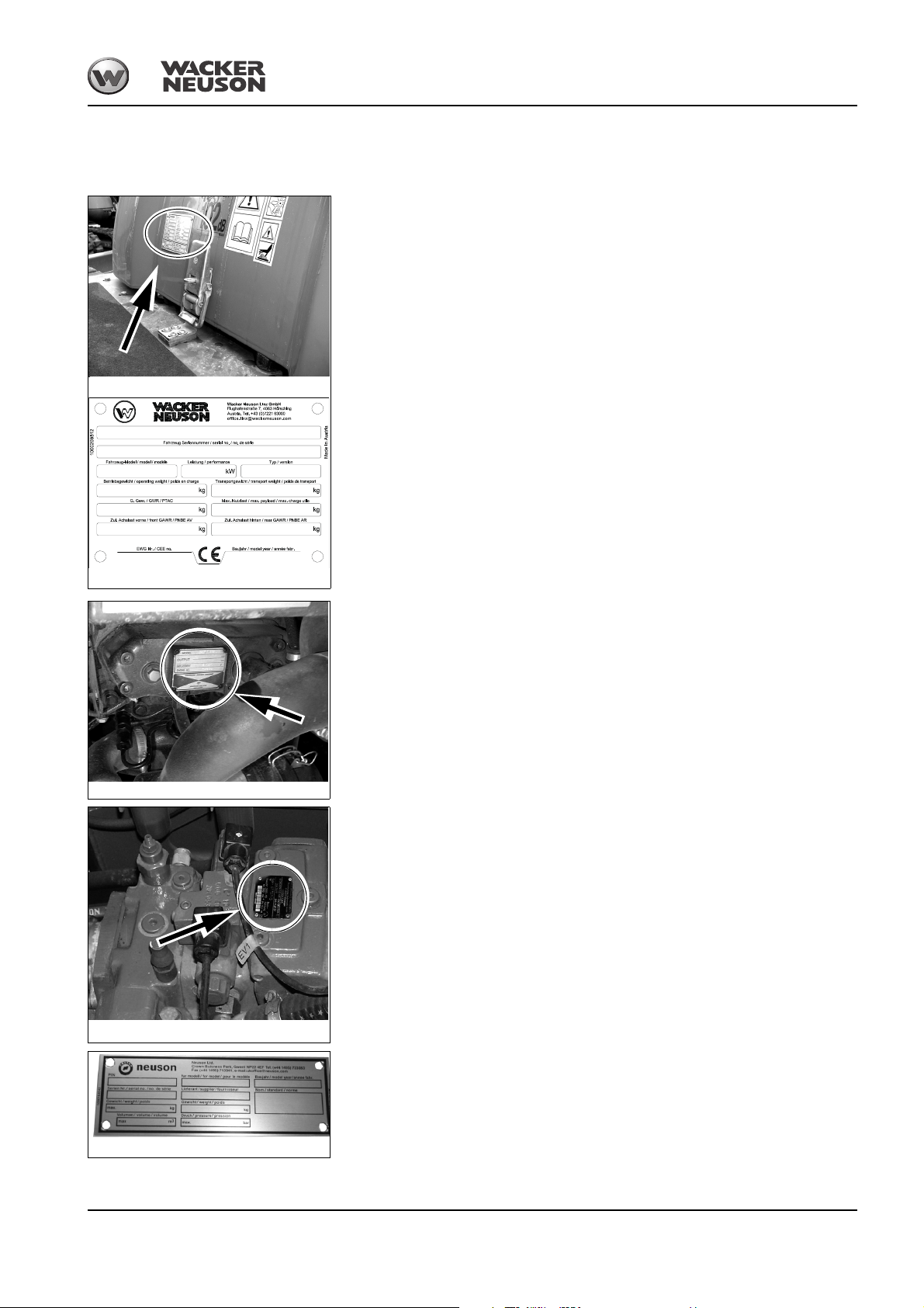
1.10 Type labels and component numbers
Fig. 1: Type label: location
Fig. 2: Type label (symbolic representation)
Fig. 3: Yanmar diesel engine number
Fig. 4: Number of variable displacement pump
Fig. 5: Rollbar type label
Serial number
The serial number is stamped on the machine chassis. It is also located on the type label.
The type label is located at the rear right of the control stand.
Type label information
Example: 1001
Model: 1001
Year: --------------PIN: (serial number) AB1001 ...
Power: --------------Mass: --------------Load: --------------Other information – see chapter 6 Technical data (1001 – 1501) on page 6-1
Introduction
Engine number
The type label (arrow) is located on the cylinder-head cover of the engine.
Example: Yanmar 46557
Hydraulic pump number
The type label (arrow) is located on the hydraulic pump housing
BA 1001/1501/2001 us – Edition 3.3 * 12001b110.fm 1-9
Rollbar number
The type label is located on the left on the rollbar
Page 18
Introduction
Important
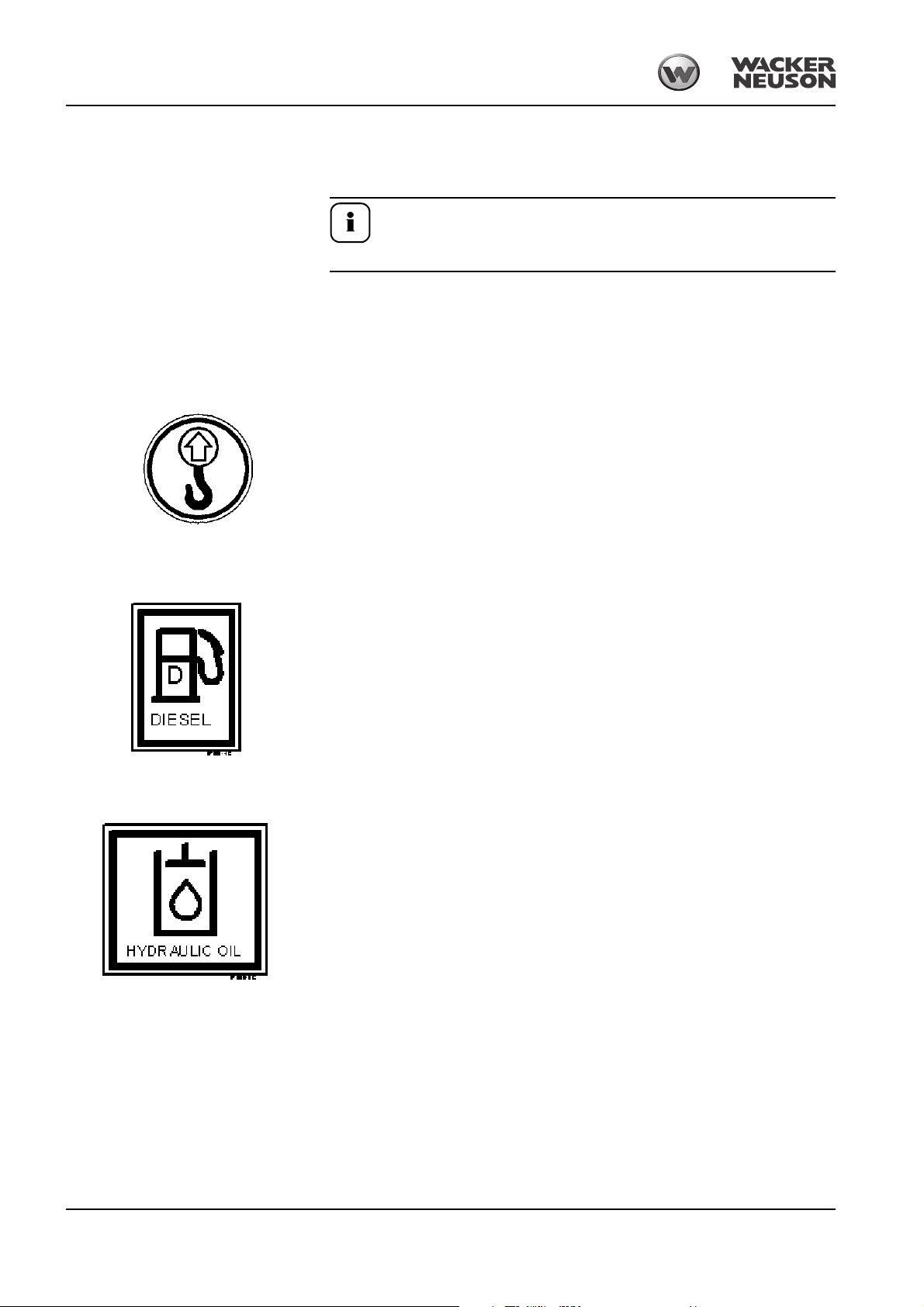
Fig. 6: Lifting eye
Fig. 7: Fuel tank
Fig. 8: Hydraulic oil reservoir
1.11 Other signs and symbols
The following states signs and symbols that do not contain explanatory text and that are
not explained in the following chapters.
Short model designations
☞1501 swivel skip = 1501S
☞1501 high-tip skip = 1501H
Meaning
Raise the machine or machine parts only by means of these eyelets.
Position
At the lifting eyes.
Type, quantity and position of the labels depend on options, country and machine.
Meaning
Machine runs with diesel fuel. Add diesel fuel only!
Position
On the fuel tank
Meaning
Reservoir contains hydraulic oil
Position
On the hydraulic oil reservoir
1-10 BA 1001/1501/2001 us – Edition 3.3 * * 12001b110.fm
Page 19
Meaning
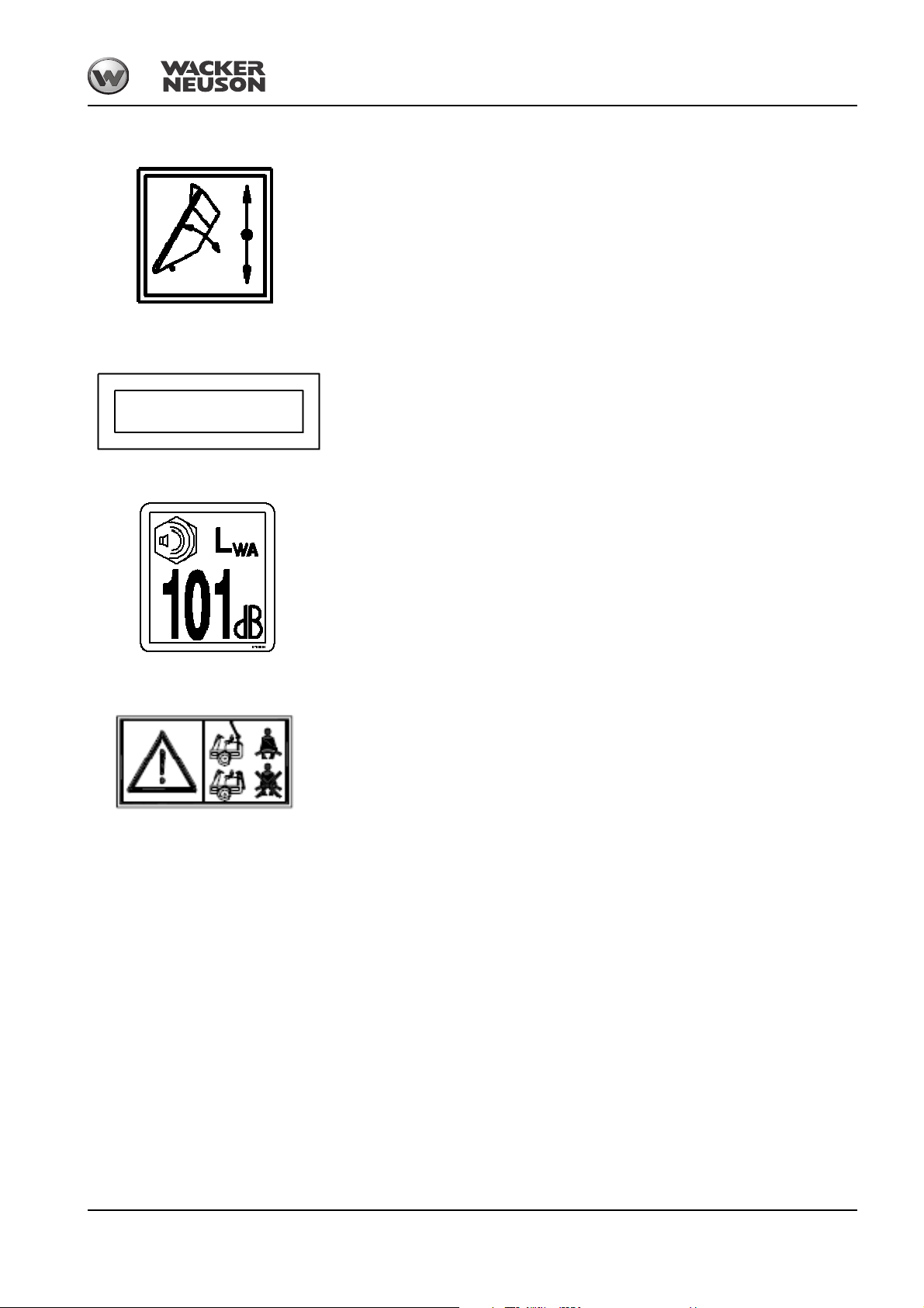
Fig. 9: Tilting out the skip
Fig. 10: Serial number
Fig. 11: Sound power level
Fig. 12: Seat belt (label version 1)
Shows how the skip can be tilted out.
Position
On the engine cover
Meaning
This label includes the serial number of the machine
Position
At the front right of the chassis
Meaning
Value of sound power level according to the 2000/14/EC standard.
Position
On the engine cover
Introduction
Meaning
Machine operation is only allowed if the rollbar is raised and locked, and if the seat belt is
fastened.
Position
On the engine cover
BA 1001/1501/2001 us – Edition 3.3 * 12001b110.fm 1-11
Page 20
Introduction
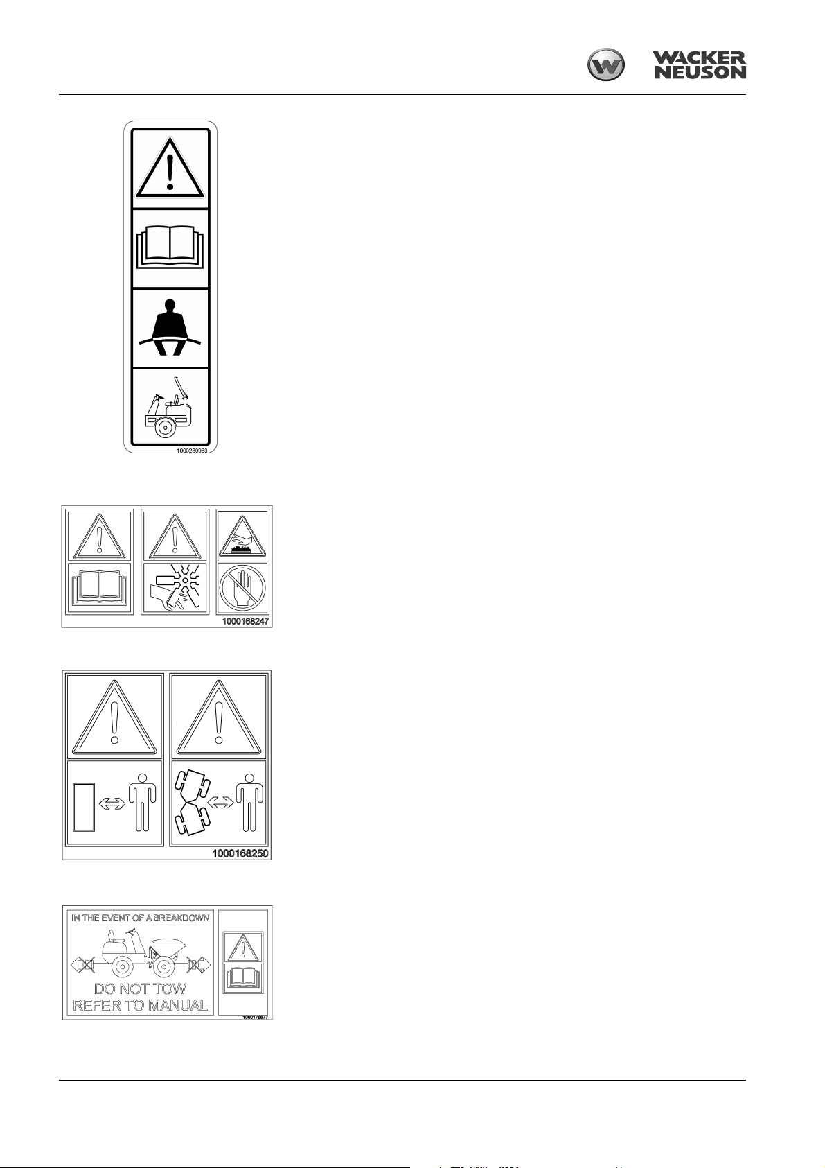
Fig. 13: Seat belt (label version 2)
Fig. 14: Rotating and hot parts
Fig. 15: Distance from machine
Fig. 16: Towing
Meaning
Machine operation is only allowed if the rollbar is raised and locked, and if the seat belt is
fastened.
Position
On the ROPS rollbar on the left in travel direction.
Meaning
Caution – rotating or hot parts! Read the Operator’s Manual
Position
On the engine cover
Meaning
Indicates that persons other than the operator must keep a safe distance from the machine
during operation!
Position
On the skip
Meaning
Machine must be towed away only by trained personnel. Follow the instructions in the
Operator’s Manual!
Position
On the engine cover
1-12 BA 1001/1501/2001 us – Edition 3.3 * * 12001b110.fm
Page 21
Introduction
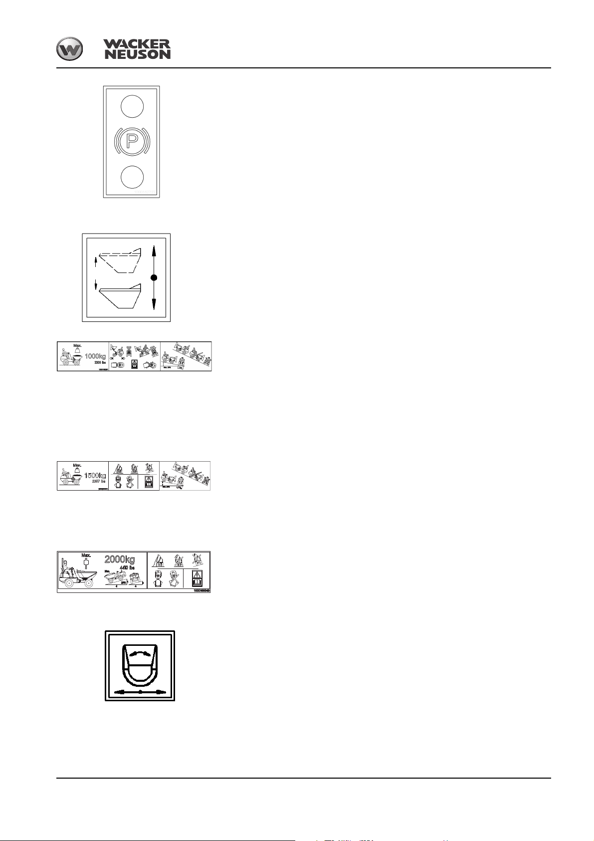
Fig. 17: Parking brake
Fig. 18: Raising and lowering the skip
Fig. 19: Angle of inclination
Fig. 20: Angle of inclination
Fig. 21: Angle of inclination
Fig. 22: Skip swivel
Label only with parking brake switch without lock
Meaning
Parking brake
Position (1501H-S, 1001)
Control stand
Meaning
Information on raising/lowering the skip
Position (1501H, 1001)
On the engine cover
Meaning
This label shows the following information/regulations:
• Maximum payload of machine.
• Tilt out the raised skip only on horizontal ground.
• Tilt out only in straight machine position.
• Maximum slope inclination allowed for tilting out downhill.
Position (1001)
On the skip
Meaning
This label shows the following information/regulations:
• Maximum payload of machine.
• Do not tilt out the skip if material is stuck in the skip.
Position (1501S)
On the skip
Meaning
This label indicates the maximum authorized angle of inclination for traveling on slopes,
whatever the position of the machine.
Position (2001)
On the skip
Meaning
Skip swivel
Position (1501S, 2001)
On the engine cover
BA 1001/1501/2001 us – Edition 3.3 * 12001b110.fm 1-13
Page 22

Introduction
Fig. 23: Loading the dumper
Fig. 24: Maintenance prop
Fig. 25: (symbolic representation)
Meaning
Loading the dumper
Position (2001)
At the rear right on the chassis
Meaning
Maintenance prop
Position
On the front chassis (1001, 1501) and on the swiveling console (2001)
Meaning
Identifies the design-specific machine speed.
Position
At the rear of the machine (left, right and rear).
1-14 BA 1001/1501/2001 us – Edition 3.3 * * 12001b110.fm
Page 23
2 Safety Information
WARNUNG
DANGER
WARNUNG
WARNINGW
WARNUNG
CAUTION
NOTICE
Important
Environment
2.1 Safety Symbols Found in this Manual
This is the safety alert symbol. It is used to alert you to potential personal hazards.
• Obey all safety messages that follow this symbol.
DANGER indicates a hazardous situation which, if not
avoided, will result in death or severe injury.
Consequences in case of non-observance.
• Obey all safety messages that follow this symbol to avoid injury or death
WARNING indicates a hazardous situation which, if not
avoided, could result in death or serious injury.
Safety Information
Consequences in case of non-observance.
• Obey all safety messages that follow this symbol to avoid possible injury or
death
CAUTION indicates a hazardous situation which, if not
avoided, could result in minor or moderate injury.
Consequences in case of non-observance.
• Obey all safety messages that follow this symbol to avoid possible minor or
moderate injury
Used without the safety alert symbol. NOTICE indicates a situation which, if
not avoided, could result in property damage.
Identifies an instruction that, when followed, provides for a more efficient and
economical use of the machine.
Failure to observe the instructions identified by this symbol can result in
damage to the environment. The environment is endangered if
environmentally hazardous material, such as waste oil, is not properly used or
disposed of.
BA 1001/1501/2001 us – Edition 3.3 * 12001b210_us.fm 2-1
Page 24

Safety Information
2.2 Warranty
2.3 Designated use
Warranty claims must be submitted to your Wacker Neuson dealer only. This requires,
among other things, following the instructions in this Operator's Manual.
• The machine is intended for:
• Moving earth, gravel, coarse gravel or ballast and rubble
• Every other application is regarded as not designated for the use of the machine.
Wacker Neuson will not be liable for damage resulting from use other than mentioned
above. The user alone will bear the risk.
• “Designated use” also includes observing the instructions set forth in this Operator's
Manual and observing the maintenance schedule.
• Machine safety can be negatively affected by performing machine modifications without
proper authority and by using spare parts, equipment, attachments and optional
equipment which have not been checked and released by Wacker Neuson. Wacker
Neuson will not be liable for damage resulting from unapproved parts or unauthorized
modifications.
• Wacker Neuson shall not be liable for personal injury and/or damage to property
caused by failure to observe the safety instructions on labels and in this Operator's
Manual, and by the negligence of the duty to exercise due care when:
• handling the machine
• operating the machine
• servicing the machine and performing maintenance on or with the machine
• repairing the machine
☞This is also applicable when special attention has not been drawn to the duty to
exercise due care.
• Read and understand this Operator's Manual before starting up, servicing or repairing
the machine. Observe all safety instructions.
• The machine may not be used for transport jobs on public roads!
2-2 BA 1001/1501/2001 us – Edition 3.3 * * 12001b210_us.fm
Page 25

2.4 General Conduct and Safety Instructions
Safety Information
Conditions for use
User training and knowledge
• The machine has been designed and built in accordance with state-of-the-art standards
and recognized safety regulations. Nevertheless, its use can constitute a risk to life and
limb of the user or of third parties, or cause damage to the machine and to other
material property.
• Read and follow this Operator's Manual and other manuals that accompany the
machine.
• The machine must only be used in accordance with its designated use and the
instructions set forth in this Operator's Manual.
• The machine must only be used by safety-conscious persons who are fully aware of the
risks involved in operating the machine.
• The machine must only be used when it is in serviceable condition. Any mechanical
dysfunctions, especially those affecting the safety of the machine, must be repaired
immediately.
• The user/owner commits himself to operate and keep the machine in perfect condition
and, if necessary or required by law, to require the operating or servicing persons to
wear protective clothing and safety equipment.
• Always keep this Operator's Manual and other manuals that accompany the machine
on hand in their storage bin at the place of use of the machine. Immediately replace an
incomplete or illegible Operator's Manual.
• All persons working on or with the machine must read and understand the safety
information in this Manual before beginning machine operation. This applies especially
to persons working only occasionally on the machine, such as performing set-up or
maintenance tasks.
• Follow and instruct the operator in legal and other mandatory regulations relevant to
accident prevention and environmental protection. These may include handling
hazardous substances, issuing and/or wearing personal protective equipment, or
obeying traffic regulations.
• The user/owner must regularly ensure that all persons entrusted with operation or
maintenance of the machine are working in compliance with this Operator's Manual and
are aware of the risks and safety factors of the machine.
Preparing for use
• Before starting up the machine, always inspect the machine to make sure that it is
ready for safe machine operation and traveling.
• Wear close-fitting work clothes that do not hinder movement. Tie back long hair and
remove all jewelry (including rings).
Modifications and spare parts
• Never make any modifications, additions or conversions to the machine and its
superstructures (for example, cab, etc.), or the machine's attachments, without the
approval of Wacker Neuson! Such modifications may affect safety and/or machine
performance. This also applies to the installation and adjustment of safety devices and
valves, as well as to welding work on load-bearing elements.
• Spare parts must comply with the technical requirements specified by Wacker Neuson.
Contact your Wacker Neuson dealer for assistance.
BA 1001/1501/2001 us – Edition 3.3 * 12001b210_us.fm 2-3
Page 26

Safety Information
2.5 General conduct and safety instructions
Organizational measures
• The machine has been designed and built in accordance with state-of-the-art standards
and the recognized safety regulations. Nevertheless, its use can constitute a risk to life
and limb of the user or of third parties, or cause damage to the machine and to other
material property
• The machine must only be used in technically perfect condition in accordance with its
designated use and the instructions set forth in the Operator's Manual, and only by
safety-conscious persons who are fully aware of the risks involved in operating the
machine. Any functional disorders, especially those affecting the safety of the machine,
must therefore be rectified immediately!
Basic rule:
• Before starting the machine ensure that:
• All safety devices and guards are in place and in working order.
• All controls operate correctly.
• The machine is set up correctly according to the instructions in the Operator's
Manual.
• The machines is clean.
• The machine's labels are legible.
• No safety devices or guards are missing or inoperative.
• Careful and prudent machine operation is the best way to avoid accidents!
• The Operator's Manual must always be at hand on the machine and must therefore be
stored in the tool kit.
Immediately replace an incomplete or illegible Operator's Manual.
• In addition to the Operator's Manual, observe and instruct the operator in all other
generally applicable legal and other mandatory regulations relevant to accident
prevention and environmental protection.
These compulsory regulations may also deal with handling hazardous substances,
issuing and/or wearing personal protective equipment, or traffic regulations
• With regard to specific operational features, e.g. those relevant to job organization, task
sequences or the persons entrusted with the task, supplement the Operator's Manual
by corresponding instructions, including those relevant to supervising and reporting
duties
• Persons entrusted with service/maintenance on the machine must have read and
understood the Operator's Manual and in particular, the chapter “Safety Instructions”,
before beginning service/maintenance. This applies especially to persons working only
occasionally on the machine, e.g., set-up or maintenance
• The user/owner must check – at least from time to time – whether the persons
entrusted with operation or maintenance of the machine are working in compliance with
the Operator's Manual and are aware of risks and safety factors
• The operator or service technician must wear personal protective equipment as
specified by local regulations.
• In the event of safety-relevant modifications or changes on the machine or of its
behavior, stop the machine immediately and report the malfunction to the competent
authority/person. Safety-relevant damage or malfunctions of the machine must be
rectified immediately
• Never make any modifications, additions or conversions to the machine and its superstructures, as well as to the attachments, which might affect safety without the approval
of Wacker Neuson! This also applies to the installation and the adjustment of safety
devices and valves, as well as to welding work on load-bearing elements
2-4 BA 1001/1501/2001 us – Edition 3.3 * * 12001b210_us.fm
Page 27

• Spare parts must comply with the technical requirements specified by Wacker Neuson.
Original spare parts can be relied to do so.
• Replace hydraulic hoses within stipulated and appropriate intervals even if no safetyrelevant defects have been detected.
• Before servicing the machine, remove jewelry, such as rings, wristwatches, bracelets
etc., and tie back long hair and do not wear loose-fitting garments, such as unbuttoned
or unzipped jackets, ties or scarves.
Injury can result from being caught up in the machinery or from rings catching on
moving parts!
• Keep the machine clean. This reduces
• Fire hazard e.g. due to oil-soaked rags lying around
• Injury hazard e.g. due to dirt or debris on the footholds, and
• Accident hazard e.g. due to dirt pile-up on the travel pedals
• Observe all safety, warning and information signs and labels on the machine
• Adhere to prescribed intervals or those specified in the Operator's Manual for routine
checks/inspections and maintenance on or with the machine!
• For service, inspection, maintenance or repair tools and workshop equipment adapted
to the task on hand are absolutely indispensable
Selection and qualification of staff, basic responsibilities
• Any maintenance on or with the machine must be performed by reliable staff only. Do
not let unauthorized persons travel or operate the machine! Observe statutory minimum
age limits!
• Employ only trained or instructed staff on the machine, and clearly and unequivocally
define the individual responsibilities of the staff for operation, set-up, maintenance and
repair!
• Define the machine operator's responsibilities – also with regard to observing traffic
regulations. Give the operator the authority to refuse instructions by third parties that
are contrary to safety
• Do not allow persons to be trained or instructed or persons taking part in a general
training course to work on or with the machine without being permanently supervised
by an experienced person!
• Work on the electrical system and equipment, on the undercarriage and the steering
and brake systems may be performed only by skilled staff which has been specially
trained for such work.
Work on the hydraulic system of the machine must be performed only by staff with
special knowledge and experience in hydraulic equipment!
• Seal off the danger zone should it not be possible to keep a safe distance.
Stop operation if persons do not leave the danger zone in spite of warning!
• Keep out of the danger zone!
Danger zone:
The danger zone is the area in which persons are endangered due to the movements of
the:
• machine
• work equipment
• additional equipment or
• material
• This also includes the area affected by falling material, equipment or by debris which
are thrown out.
The danger zone must be extended by 0.5 m in the immediate vicinity of
• buildings
• scaffolds or
• other elements of construction
Safety Information
BA 1001/1501/2001 us – Edition 3.3 * 12001b210_us.fm 2-5
Page 28

Safety Information
2.6 Safety instructions regarding operation
Normal operation
• Avoid any operational mode that might be prejudicial to safety!
• Before beginning machine operation, familiarize yourself with the surroundings and
circumstances of the work site. These are e.g. obstacles in the traveling area or the job
site, the soil bearing capacity and any necessary barriers separating the work site from
public roads
• Take the necessary precautions to make sure the machine is used only when in a safe
and reliable state!
Operate the machine only if all protective and safety-oriented devices, e.g. removable
safety-devices, soundproofing elements and mufflers etc., are in place and fully
functional!
• Check the machine at least once a day/per work shift for visible damage and defects.
Report any changes (incl. changes in the machine's operational behavior) to the
competent organization/person immediately! If necessary, stop the machine immediately and lock it!
• In the event of malfunctions, stop the machine immediately and lock it! Have any
defects rectified immediately!
• Start and operate the machine from the operator‘s seat only!
• Perform start-up and shut-down procedures in accordance with the Operator's Manual,
and observe the indicators!
• Before putting the machine into operation (start-up/moving), make sure no one is at risk
by putting the machine into operation!
• Before machine travel, and also after interrupting operation, check whether the service
brake, the parking brake (the drive must be switched off if the parking brake is applied!)
and the signalling and the light systems are functional!
• When traveling on public roads, ways and places, observe the local traffic regulations in
force and, if necessary, make sure beforehand that the machine is in a condition
perfectly compatible with these regulations!
• Always switch on the lights in conditions of poor visibility and after dark.
• Do not carry any other persons apart from the operator!
• When crossing underpasses, bridges and tunnels, or when passing under overhead
lines always make sure there is enough clearance!
• Always keep at a safe distance from the edges of building pits and slopes!
• When working in buildings or in enclosed areas, look out for:
• Height of the ceiling/clearances
• Width of entrances
• Maximum load of ceilings and floors
• Sufficient room ventilation – poisoning hazard! (exhaust)
2-6 BA 1001/1501/2001 us – Edition 3.3 * * 12001b210_us.fm
Page 29

Safety Information
• Avoid any operation that might be a risk to machine stability!
• On sloping terrain always adapt your travel speed to the prevailing ground conditions!
Never change to lower gear on a slope but always before reaching it!
• Before leaving the seat always secure the machine against unintentional movement
and unauthorized use!
• Before starting work check whether
• all safety devices are properly installed and functional.
• dirt has been removed from all footholds.
• Before starting machine travel or operation:
• Make sure visibility is sufficient!
• Adjust your correct seat position, never adjust the seat when traveling or operating!
• Always fasten the seat belt if the rollbar is raised!
• Inspect the immediate area and ensure no one is in the danger zone.
• On the job site the operator is responsible for third parties!
• Caution when handling fuel – increased fire hazard!
• Make sure fuel does not come into contact with hot parts!
Stop the engine before refueling, do not smoke and avoid open flames or sparks.
• Never get on or off during travel or operation! Never jump off the machine!
• Should it be too dark for performing work safely, provide additional lighting on the job
site.
• Installed work lights must not be switched on for travel on public roads. They can be
switched on in work operation if users of public roads are not blinded.
• Adjust the travel speed to your abilities and the circumstances.
• Always adapt your travel speed to the road and ground conditions, and to the visibility
conditions. Ask someone to guide you in case of difficult passages or obstacles.
Always avoid tipping over the dumper by traveling appropriately and slowly as required.
This applies in particular to rough terrain, the edges of trenches, curves and emergency
braking. Use only the low speed range when traveling off-road (turtle indicator light on
the instrument panel).
• Proceed with extreme care when working on slopes. The dumper can be traveled on
firm ground in all positions on slopes up to 25 % steep. On slopes that are less steep if
you expect the wheels on one side to sink in. When traveling on slopes steeper than 25
%, travel the loaded dumper only with the skip facing uphill, i.e. travel downhill
reversing. When traveling downhill with an empty skip on slopes steeper than 25 %, the
skip must face downhill.
• Make sure the engine cover is closed and locked before starting the dumper.
• When traveling downhill with a full skip, travel slowly and reduce engine speed by
slowly reducing the pressure on the accelerator pedal. The dumper brakes hydraulically
at idling speed of the diesel engine. The center of gravity of the payload is shifted to the
front on slopes. Reverse downhill if you are not sure.
• Apply the parking brake when parking the machine. If possible, do not park the dumper
on slopes. If this cannot be avoided, use wheel chocks, etc. Lower the skip before
leaving the dumper. Apply the parking brake only in an emergency during machine
travel.
• Keep the base plate of the skip in a clean condition so that the material is easily
dumped out of the skip. Load only material that can be easily dumped out. Tilt out sticky
or frozen material only to the front and with the dumper in straight-ahead position on
level ground. As you raise the skip, watch whether the material is dumped out before
fully raising the skip. Failure to watch whether the material is dumped out correctly can
cause the dumper to tip over.
BA 1001/1501/2001 us – Edition 3.3 * 12001b210_us.fm 2-7
Page 30

Safety Information
WARNUNG
WARNINGW
Operation with lowered rollbar
• Never travel too close to the edges of pits, precipices, etc., since the pressure of the
wheels on the ground can cause the edge to give way. If edges are secured sufficiently
and a barrier prevents the ground from giving way, you may travel closer to edges of
pits, precipices, etc.
• Never tilt out material into trenches in which there are persons. If the operator cannot
see into the trench, he must be instructed by a person who can see into the trench.
• Always make sure the brakes are in a perfect condition.
Crushing hazard during machine travel with lowered rollbar!
Can cause severe injuries or death.
• Depending on the situation, travelling over very short distances with a lowered
rollbar is allowed (in case of low clearance heights, for example), however only
if the following conditions are fulfilled:
• Obtain the approval of the competent national authority.
• Machine operation with a lowered rollbar is prohibited.
• Machine travel is only allowed on absolutely level ground.
• Avoid tipping movements of the machine under all circumstances.
• Operation in areas involving a risk of falling objects or fragments flying
around is prohibited.
• Do not fasten the seat belt in order to be able to leave the machine
immediately in an emergency.
• Wear protective equipment (protective clothing, safety glasses, for
example).
Trailer operation
In spite of being equipped with towing gear, the dumper is not a tractor and may not be
used as such in difficult terrain. If the dumper is used on construction sites for towing trailers, weight down the skip with 25 % of the payload. However, the towed equipment including the weight in the skip may not exceed the dumper's payload. Secure the towing pin of
the towing gear with a split pin!
2-8 BA 1001/1501/2001 us – Edition 3.3 * * 12001b210_us.fm
Page 31

2.7 Staff Qualifications and Basic Responsibilities
User/owner responsibility
• Only allow trained and experienced individuals to travel, maintain or repair the
machine. Never let unauthorized or underaged persons travel or operate the machine.
• Clearly and unequivocally define the individual responsibilities of the staff for operation,
maintenance and repair.
• Define the machine operator's responsibilities on the job site and for observing traffic
regulations. Give the operator the authority to refuse instructions by third parties that
are contrary to safety.
• Do not allow persons to be trained or instructed by anyone other than an experienced
person. Also, Never allow persons taking part in a general training course to operate
the machine without being permanently supervised by an experienced person.
Repair person qualifications
• Service on the electric system and equipment, on the undercarriage and the steering
and brake systems may be performed only by skilled individuals who have been
specially trained for such work.
• Service on the hydraulic system of the machine must be performed only by staff with
special knowledge and experience in hydraulic equipment.
Safety Information
2.8 Safety instructions regarding operation
Preparing for use
• Keep the machine clean. This reduces the risk of fire hazards (such as from
combustible materials like rags)and reduces the risk of injury or operational accidents
that may be caused by dirt build-up on the travel pedals or footholds.
• Observe all safety, warning and informational signs and labels on the machine.
• Start and operate the machine from the operator‘s seat only.
• The operator must sit in the seat, fasten and tighten the seat belt before putting the
machine into operation.
• Always adjust the seat position before starting machine operation. Never change the
seat position during machine travel or operation.
• Make sure that all safety devices are properly installed and functional before starting
machine operation.
• Before putting the machine/attachment into operation (startup/moving), make sure that
no one in the immediate vicinity will be at risk.
Startup and shutdown
• Perform startup and shutdown procedures according to this Operator's Manual.
• Observe all indicator lights.
• Do not use starting fluid (for example, ether), especially in those cases in which a
heater plug (intake air pre-heating) is used at the same time.
• Make sure the travel levers, the signaling and the light systems are functional before
operating the machine, and also before restarting after a interruption of machine
operation.
• Make sure that the service brake and the parking brake are functional before operating
the machine, and also after an interruption of machine operation. The machine will not
start unless the parking brake is applied. The drive must be switched off if the parking
brake is applied
BA 1001/1501/2001 us – Edition 3.3 * 12001b210_us.fm 2-9
Page 32

Safety Information
Job Site awareness
• Familiarize yourself with the surroundings and circumstances of the job site before
beginning machine operation. Be aware of:
• obstacles in the working and traveling area
• the soil weight-bearing capacity
• any necessary barriers separating the job site from public roads
• Always keep a safe distance from the edges of building pits and slopes.
• Look out for the following when working in buildings or in enclosed areas:
• Height of the ceiling/clearances
• Width of entrances
• Maximum load of ceilings and floors
• Sufficient room ventilation—carbon monoxide poisoning hazard!
• Observe the danger zone. See “Danger zone awareness”.
• Use the rearview mirror to stay aware of job site obstacles and personnel.
• Always switch on the work lights in conditions of poor visibility and after dark. However,
make sure that users of public roads will not be temporarily blinded by the work lights.
• Provide additional lighting on the job site if the lights of the machine are not sufficient
for performing safe operation.
• Travel slowly on meadows, on leaves or wet steel plates. The machine can slip even if
the ground is level.
Danger zone awareness
Operating the machine
Special operating notes
• The danger zone is the area in which persons are endangered due to the movements
of the machine, work equipment, additional equipment, or material.
• The danger zone also includes the area affected by falling material, equipment or
construction debris. The danger zone must be extended by 0.5 m (20”) in the
immediate vicinity of buildings, scaffolds, or other elements of construction.
• Seal off the danger zone if it is not possible to keep a safe distance. Stop operating
immediately if persons do not leave the danger zone in spite of warnings!
• Never operate the machine if you are standing on the ground.
• Operate the machine only when you are seated and you have fastened your seat belt.
Stop the engine before releasing the seat belt.
• On sloping terrain, adapt your travel speed to the prevailing ground conditions.
• Never get on or off a machine during travel or operation, and never jump off the
machine.
• Always adapt your travel speed to the road and ground conditions, and to the visibility
conditions. Ask for help in navigating difficult passages or obstacles. To avoid tipping
the dumper, travel appropriately and slowly as conditions dictate. This applies in
particular to rough terrain, the edges of trenches, curves and emergency braking. Use
only the low speed range when traveling off-road (see the turtle indicator light on the
instrument panel).
• Make sure the engine cover is closed and locked before starting the dumper.
2-10 BA 1001/1501/2001 us – Edition 3.3 * * 12001b210_us.fm
Page 33

Carrying passengers
Mechanical integrity
Safety Information
• Apply the parking brake when parking the machine. If possible, do not park the dumper
on slopes. If this cannot be avoided, use wheel chocks, etc. Lower the skip before
leaving the dumper. Apply the parking brake only in an emergency during machine
travel.
• Keep the base plate of the skip in a clean condition so that the material is easily
dumped out of the skip. Load only material that can be easily dumped out.
• Never travel too close to the edges of unsecured pits, precipices, etc. The pressure of
the wheels on the ground may cause the edge to give way.
• Never tilt out material into trenches where people are working. If the operator cannot
see into the trench, he or she must be guided by someone who can see into the trench.
• Always make sure the brakes are in perfect condition.
• Apart from the operator, do not allow anyone to ride on the machine.
• Never lift, lower, or carry persons in the work equipment or attachments.
• Never install a man basket or a working platform to the machine.
• Take the necessary precautions to make sure the machine is used only when in a safe
and reliable state.
• Operate the machine only if all protective and safety-oriented devices (ROPS,
removable safety devices, soundproofing elements, mufflers, etc.) are in place and fully
functional.
• Check the machine at least once a day/per machine operation shift for visible damage
and defects. Report any changes, including changes in the machine's operational
behavior, to your supervisor immediately!
• If the machine is behaving unpredictably, stop the machine immediately, lock it and
report the malfunction to the competent authority/person. Safety-relevant damage or
malfunctions of the machine must be rectified immediately.
Traveling on public roads
• When traveling on public roads, ways and places, observe all applicable traffic
regulations. If necessary, make sure that the machine is in compliance with these
regulations.
• When crossing underpasses, gates, bridges and tunnels, or when passing under
overhead lines, make sure the clearance height and width are sufficient.
BA 1001/1501/2001 us – Edition 3.3 * 12001b210_us.fm 2-11
Page 34

Safety Information
2.9 Trailering and Transport
Trailers
Transport
• Even though the dumper is equipped with towing gear, it is not a tractor and may not be
used as such in difficult terrain.
• If the dumper is used on construction sites for towing trailers, weight the skip with 25 %
of the payload. However, do not exceed the dumper's maximum payload with the
combination of towed equipment and the weight in the skip!
• Secure the towing pin of the towing gear with a split pin.
• Use special care when coupling trailers, and couple them with the specially required
devices only.
• Always secure trailers against unintentional movement.
• If optional equipment such as a trailer is installed, make sure that all lights and
associated indicator lights are installed and functional.
• The machine must be towed, loaded and transported only in accordance with
procedures described in this Operator's Manual.
• For towing the machine, observe the prescribed transport position, admissible speed
and itinerary.
• Make sure that the vehicle transporting the machine has a sufficient capacity and
payload.
• Safely secure the machine on the transporting vehicle. Use the specified tie-down
points.
2.10 Temperature Range
The machine may only be used between a maximum +45°C (113°F) and minimum -15°C
(5°F). Contact your Wacker Neuson dealer if you intend to use the machine in other
temperature ranges. Store the machine in a dry place at room temperature (about 15°C, or
59°F). Observing these temperature ranges will help to prolong the machine's service life.
2.11 Safety Guidelines for Maintenance
General maintenance notes
• Adhere to prescribed intervals or those specified in this Operator's Manual for routine
checks/inspections and maintenance.
• For inspection and maintenance, ensure that all tools and workshop equipment are
adapted to the task that must be performed.
• Replace hydraulic hoses within stipulated and appropriate intervals even if no
safety-relevant defects have been detected.
• Make sure all consumables and replaced parts are disposed of safely and with
minimum environmental impact.
• Always tighten any screws, electrical connections, or hose connections that may have
been loosened during maintenance.
• Upon completion of the maintenance on or with the machine, immediately refit and
check any safety devices removed for set-up or maintenance purposes.
2-12 BA 1001/1501/2001 us – Edition 3.3 * * 12001b210_us.fm
Page 35

Personal safety measures
Safety Information
• Brief the staff and the operator before beginning maintenance or repair. Appoint
someone to supervise the activities.
• Always work in groups of two. Both persons must be trained on the machine—one
person must be seated on the seat and maintain visual contact with the other person.
• Observe the specific safety instructions in the Maintenance section of this Operator's
Manual.
• Always keep a safe distance from all rotating and moving parts, for example, fan
blades, V-belt drives, PTO shaft drives, fans, etc.
• Before starting to work on hazardous machine parts, always ensure safety devices and
guards are in place.
• Use extreme caution when working on the fuel system due to the increased fire hazard.
• Engine and muffler system become very hot during operation and require cool-down
time after machine is shut off. Avoid contact with hot parts. Wait for the machine to cool
before touching components.
• Retainer pins can fly out or splinter when struck with force. Avoid striking the pins
during operation, repair, or maintenance.
• Do not use starting fluid (for example, ether), especially in those cases in which a
heater plug (intake air pre-heating) is used at the same time.
Preparing for maintenance and repair work
• Prior to performing repair and maintenance, always attach a warning label such as
“Repair work—do not start machine!” to the control elements as a precautionary
measure.
• Observe the startup and shutdown procedures set forth in this Operator's Manual. This
applies to any task concerning the operation, conversion or adjustment of the machine
and its safety-oriented devices, or any work related to inspection and maintenance.
• Prior to performing assembly maintenance on the machine, make sure no movable
parts will roll away or start moving.
• Perform maintenance only if:
• the machine is positioned on firm and level ground
• secured against unintentional movement
• all hydraulically movable attachments and working equipment have been lowered to
the ground
• the engine is switched off
• the starter key has been removed
• Perform maintenance beneath a raised machine, attachments or additional equipment
only if a safe and secure support has been provided. The use of hydraulic hydraulic
cylinders or jacks as the sole method of support does NOT sufficiently secure raised
machines or equipment/attachments!
Performing maintenance and repairs
• Observe the adjustment, maintenance and inspection activities and intervals set forth in
this Operator's Manual, including information on the replacement of parts and partial
equipment. These activities must be performed only by qualified personnel.
• Disconnect the negative battery terminal when working on the electric system.
• Do not allow the machine to be serviced, repaired, or test-traveled by unauthorized
staff.
• If maintenance with the engine running cannot be avoided, lower the skip and apply the
parking brake.
BA 1001/1501/2001 us – Edition 3.3 * 12001b210_us.fm 2-13
Page 36

Safety Information
2.12 Special hazards
Battery
• Wear a safety harness when performing elevated maintenance. Keep all handles,
steps, handrails, platforms, landings and ladders free from dirt, snow and ice.
• Always use specially designed or otherwise safety-oriented ladders and working
platforms to perform overhead assembly maintenance. Never use machine parts or
attachments/superstructures as a climbing aid!
• Do not use the work equipment as lifting platforms for persons.
• In accordance with this Operator's Manual and instructions for the respective assembly,
release the pressure in all system sections and pressure lines (hydraulic system)
before performing any maintenance.
• In case of a frozen battery or of an insufficient electrolyte level, do not try starting the
machine with battery jumper cables. The battery can burst or explode.
• Batteries contain caustic sulphuric acid. When handling the battery, observe the
specific safety instructions and regulations relative to accident prevention.
• A volatile oxyhydrogen mixture forms in batteries during normal operation and
especially when charging. Always wear gloves and eye protection when working with
batteries.
• Starting the machine with a battery jumper cable can be hazardous if performed
improperly. Observe the safety instructions regarding the battery.
Tracks (track dumpers)
Electric energy
• Repair on the tracks must be performed only by trained technical staff or by a Wacker
Neuson service center.
• Malfunctioning tracks reduce the machine's operational safety. Therefore, check the
tracks regularly for cracks, cuts or other damage.
• Check track tension at regular intervals.
• Use only original fuses with the specified current rating.
• In case of electric system malfunctions, stop the machine immediately, disconnect the
battery (by using the battery master switch)and perform troubleshooting procedures.
• During machine operation, maintain a safe distance from overhead electric lines! If
machine operation must be performed close to overhead lines, the equipment and
attachments must be kept well away from them.
• If the machine comes into contact with a live wire:
• Immediately travel the machine out of the danger zone.
• Warn others against approaching and touching the machine.
• Do not leave the machine until the line that has been touched or damaged has been
safely de-energized!
• Make sure that service on the electric system is performed only by a technician with
appropriate training, in accordance with applicable electrical engineering codes.
• Inspect and check the electric equipment of the machine at regular intervals. Defects
such as loose connections or scorched cables must be repaired immediately.
• Observe the operating voltage of the machine/attachments.
• Always remove the grounding strap from the battery when working on the electric
system.
2-14 BA 1001/1501/2001 us – Edition 3.3 * * 12001b210_us.fm
Page 37

Gas, dust, steam, smoke
Hydraulics
Safety Information
• Operate the machine only on adequately ventilated premises! Before starting internal
combustion engines or operating fuel-operated heating systems on enclosed premises,
make sure there is sufficient ventilation!
Observe the regulations in force at the respective site!
• Perform welding, flame-cutting and grinding work on the machine only if this has been
expressly authorized. There can be a risk of explosion and fire, for example!
• Before performing welding, flame-cutting and grinding work, clean the machine and its
surroundings from dust and other inflammable substances, and make sure the
premises are adequately ventilated – explosion hazard!
• Service on the hydraulic equipment of the machine must be performed only by persons
having specific technical knowledge and experience in hydraulic systems!
• Check all lines, hoses and screw connections regularly for leaks and obvious damage!
Repair any damage and leaks immediately! Splashed oil can cause injury and fire.
• In accordance with the Operator's Manual/instructions for the respective assembly,
release the pressure in all system sections and pressure lines (hydraulic system) to be
opened before performing any maintenance/repairs!
• Hydraulic and compressed-air lines must be laid and fitted properly. Make sure no
connections are interchanged. The fittings, lengths and quality of the hoses must
comply with the technical requirements
• Check all lines, hoses and threaded fittings regularly for leaks and obvious damage!
Repair any damage and leaks immediately. Leaking oil may cause injury and fire!
Noise
Oil, grease and other chemical substances
MSDS
• Close all sound baffles during operation.
• Wear ear protection. This is especially important when performing hammer operations
or working in enclosed areas.
• When handling oil, grease and other chemical substances (e.g. battery electrolyte –
sulphuric acid), observe the product-related safety regulations (safety data sheet)!
• Be careful when handling hot consumables – burn hazard!
• When handling oil, grease and other chemical substances such as battery electrolyte or
hydraulic fluid, observe the product-related safety regulations (Material Safety Data
Sheet: MSDS).
BA 1001/1501/2001 us – Edition 3.3 * 12001b210_us.fm 2-15
Page 38

Safety Information
WARNUNG
WARNINGW
Tires (wheel dumpers)
• Repair on the tires must be performed only by trained technical staff or by a Wacker
Neuson service center.
• Malfunctioning tires reduce the machine's operational safety. Therefore, check the tires
regularly for cracks, cuts or other damage.
• Check the tire pressure at regular intervals.
2.13 Safety Guidelines while using Internal Combustion Engines
Internal combustion engines present special hazards during
operation and fueling. Failure to follow the warnings and
safety guidelines could result in severe injury or death.
• Read and follow the warning instructions in the engine owner's manual and the
safety guidelines below.
Guidelines for running the engine
CALIFORNIA
Proposition 65 Warning
Engine exhaust, some of its constituents, and certain vehicle components contain or emit
chemicals known to the State of California to cause cancer and birth defects or other
reproductive harm.
• Keep the area around muffler pipe free of flammable materials.
• Check the fuel lines and the fuel tank for leaks and cracks before starting the engine.
Do not run the machine if fuel leaks are present or the fuel lines are loose.
• Engine exhaust can kill you in minutes! Engine exhaust contains carbon monoxide.
This is a poison you cannot see or smell. Never run the machine indoors or in an
enclosed area such as a deep trench unless adequate ventilation, through such items
as exhaust fans or hoses, is provided.
• Do not smoke while operating the machine.
• Do not run the engine near open flames.
• Do not touch the engine or muffler while the engine is running or immediately after it
has been turned off.
• Do not operate a machine when its fuel cap is loose or missing.
• Do not remove the radiator cap when the engine is running or hot. The radiator fluid is
hot and under pressure, and may cause severe burns!
2-16 BA 1001/1501/2001 us – Edition 3.3 * * 12001b210_us.fm
Page 39

Guidelines for fueling the engine
Safety Information
When fueling the engine:
• Clean up any spilled fuel immediately.
• Refill the fuel tank in a well-ventilated area.
• Replace the fuel tank cap after refueling.
When fueling the engine:
• Do not smoke.
• Do not refuel a hot or running engine.
• Do not refuel the engine near an open flame.
BA 1001/1501/2001 us – Edition 3.3 * 12001b210_us.fm 2-17
Page 40

Safety Information
2-18 BA 1001/1501/2001 us – Edition 3.3 * * 12001b210_us.fm
Page 41

3Operation
Operation
This chapter describes the controls, and contains information on the function and handling
of the indicator lights and controls on the control stand.
The pages stated in the table refer to the description of the controls.
A combination of digits, or a combination of digits and letters (for example 40/18 or 40/A)
used for identifying the control elements, means: fig. no. 40/control element no. 18 or position A in fig. no. 40
Figures carry no numbers if they are placed to the left of the text.
The symbols used in the description have the following meanings:
• Identifies a list
• Subdivision within lists or an activity. Follow the steps in the recommended order
☞Identifies an activity
➥Description of the effects or results of an activity
n. s. = not shown
Opt = option
Stated whenever controls or other components of the machine are installed as an option.
BA 1001/1501/2001 us – Edition 3.3 * 12001b320.fm 3-1
Page 42

Operation
Description of 1001/1501 components (overview)
Pos.
3-2 BA 1001/1501/2001 us – Edition 3.3 * * 12001b320.fm
Designation
1 Rear chassis
2Front chassis
3 Lift frame
4 Articulated joint
5 Operator seat
6 Control stand
7 Tilt console
8 Engine cover
9 Parallel lift
10 Skip
11
Lift cylinder
12
Tilt cylinder (not shown)
13
Steering cylinder
Page 43

Operation
Description of 1501S components (overview)
Pos.
BA 1001/1501/2001 us – Edition 3.3 * 12001b320.fm 3-3
Designation
1 Operator seat
2 Control stand
3Skip
4 Swivel centring
5 Swiveling console
6 Tilt cylinder
7 Articulated joint
8 Steering cylinder
9 Rear chassis
10 Engine cover
Page 44

Operation
3.1 Description of 2001S components (overview)
Pos.
3-4 BA 1001/1501/2001 us – Edition 3.3 * * 12001b320.fm
Designation
1 Rear chassis
2Front chassis
3 Swiveling console
4 Articulated joint
5 Operator seat
6 Control stand
7 Mudguard
8 Engine cover
9 Swivel centring
10 Skip
11 Swiveling cylinder
12 Tilt cylinder
13 Steering cylinder
14 Rollbar
Page 45

Operation
3.2 Description of 2001 SLE components
Pos.
BA 1001/1501/2001 us – Edition 3.3 * 12001b320.fm 3-5
Designation
1 Lift frame
2 Lift cylinder
3 Bucket cylinder
4Bucket
5 Fastening mount
6 Articulation (large)
7 Articulation (small)
Page 46

Operation
6
7
8
9
10
11
12
13
3
3.3 1001/1501/1501S operating equipment up to serial no. AB ...
Driving direction lever
Pos.
Designation
1 Accelerator pedal 14 Hour meter
2 Parking brake 15 Fuel level indicator
3 Preheating start switch 16 Lever “Tilting out/lowering the skip”
4 Travel direction lever 17 Lever “Raising/lowering the skip”
5 Horn 18 Bar for horizontal seat adjustment
6 Alternator charge indicator light
7 Engine oil pressure indicator light
8 Parking brake indicator light
9 Engine temperature indicator light
10 Spare fuel indicator light
11 Not assigned
12 Hydraulic oil filter indicator light
13 Preheating indicator light
3-6 BA 1001/1501/2001 us – Edition 3.3 * * 12001b320.fm
Page 47

Operation
16
17
13
13
15
14
13
8
10
9
11
12
13
18
19
20
7
3
6
5
4
1
2
3.4 1001/1501/1501S operating equipment from serial no. AB ...
Pos.
Designation
1 Accelerator pedal 14 Hydraulic oil filter indicator light
2 Service brake 15 Preheating indicator light
3 Parking brake 16 Hour meter
4 Preheating start switch 17 Fuel level indicator
5 Travel direction lever 18 Lever “Tilting out/lowering the skip”
6 Horn 19 Lever “Raising/lowering the skip”
7 Display element 20 Bar for horizontal seat adjustment
8 Alternator charge indicator light
9 Engine oil pressure indicator light
10 Parking brake indicator light
11 Engine temperature indicator light
12 Turn indicator light
13 Not assigned
BA 1001/1501/2001 us – Edition 3.3 * 12001b320.fm 3-7
Page 48

Operation
4
21
6
7
8
9 10
11
12
13
14
15
16
17
1st row of indicator lights 2nd row of indicator lights
3rd row of indicator lights
3
19
20
5
1
18
23
2
22
24
25
3.5 2001/2001SLE operating equipment
Pos. Designation Pos. Designation
1
Accelerator pedal
2
Parking brake
3
Preheating start switch
4
Travel direction lever
5
Horn
6
Alternator charge function indicator light
7
Engine oil pressure indicator light
8
Parking brake indicator light
9
Engine temperature indicator light
10
Spare fuel indicator light
11
Not assigned
12
Hydraulic oil filter indicator light
13
Not assigned
High beam indicator light
Not assigned
Preheating indicator light
Turn indicator light
Hour meter
Fuel level indicator
Lever for tilting/lowering the skip
Lever: swivel skip
Hydrostatic brake pedal
Light switch
Seat adjustment lever
Skip/loader unit switch (option 2001)
14
15
16
17
18
19
20
21
22
23
24
25
3-8 BA 1001/1501/2001 us – Edition 3.3 * * 12001b320.fm
Page 49

3.6 Putting into operation
Safety instructions
Putting into operation for the first time
Operation
• Use footholds and handles to access and leave the machine
• Never use control elements as handles
• Never get on a moving machine. Never jump off the machine
Important information
• The machine may only be put into operation by authorized personnel – see chapter
Selection and qualification of personnel, basic responsibilities on page 2-4 and –
see chapter 2.5 Safety instructions regarding operation on page 2-5 of this
Operator’s Manual.
• The personnel must have read and understood this Operator’s Manual before putting
the machine into operation.
• The machine may only be used in technically perfect condition in accordance with its designated use and the instructions set forth in the Operator’s Manual, and only by safetyconscious persons who are fully aware of the risks involved in operating the machine.
• Go through the “Start-up” checklist in the following chapter.
Running-in period
Handle the machine carefully during its first 50 operating hours.
The future performance and service life of the machine are heavily dependent on the
observance of the following recommendations during the running-in period.
• Do not overload the machine, but at the same time do not travel too cautiously either,
as the machine will never reach its proper operating temperature
• Do not run the engine at high speed for extended periods
• Increase the load gradually while varying the engine speed
• Strictly observe the maintenance schedules in the appendix
– see chapter 5.16 Maintenance plan 2001 (overview) on page 5-39
BA 1001/1501/2001 us – Edition 3.3 * 12001b320.fm 3-9
Page 50

Operation
Check lists
Start-up checklist
The checklists below are intended to assist you in checking and monitoring the machine
before, during and after operation.
These checklists cannot claim to be exhaustive; they are merely intended as an aid for you
in fulfilling your duties as a conscientious operator.
The checking and monitoring work listed below is described in greater detail in the following chapters.
If the answer to one of the following questions is NO, first rectify the cause of the fault
before starting or continuing work.
Check the following points before putting the machine into operation or starting the engine:
No.
Question
1
Enough fuel in the tank? (➠ 5-5)
2
Coolant level OK? (➠ 5-13)
3
Remove water in the diesel fuel prefilter (➠ 5-7)
4
Engine oil level OK? (➠ 5-10)
5
Oil level in hydraulic oil reservoir OK? (➠ 5-21)
7
V-belt condition and tension checked? (➠ 5-18)
8
Lubrication points greased?
9
Check hydraulic hoses, connections and cylinder seals for leaks
10
Firm position of battery terminals
11
Tires checked for cracks, cuts, etc. ? (➠ 5-26)
12
Footholds clean?
13
Engine cover locked with the buckle? (➠ 3-29)
Especially after cleaning, maintenance or repair work:
14
➥Rags, tools and other loose objects removed?
15
Seating position adjusted correctly? (➠ 3-27)
16
Rollbar raised and locked?
17
Seat belt fastened? (➠ 3-28)
✔
3-10 BA 1001/1501/2001 us – Edition 3.3 * * 12001b320.fm
Page 51

Operation checklist
Operation
After starting the engine and during operation, check and observe the following points:
“Parking” checklist
No. Question
1
Anyone in the danger zone of the machine?
Indicator lights for engine oil pressure and alternator charge function gone
2
out? (➠ 3-13)
3
Temperature indicators for engine coolant do not illuminate? (➠ 3-13)
4
Accelerator and brake pedals working correctly? (➠ 3-20)
Check and observe the following points when parking the machine:
No. Question
1
Skip lowered?
2
Travel lever in neutral position?
3
Parking brake applied?
4
Starting key removed?
When parking on public roads:
5
Machine adequately secured?
When parking on slopes:
Machine additionally secured with chocks under the wheels to prevent it from
6
rolling away?
✔
✔
BA 1001/1501/2001 us – Edition 3.3 * 12001b320.fm 3-11
Page 52

Operation
1
0
2
3
Fig. 26: Preheating start switch
4
Fig. 27: Accelerator pedal (symbolic representation)
25
3.7 Machine travel
Preheating start switch (overview)
Accelerator pedal (overview)
Position
Function Power consumer
0
Insert or remove the starting key None
All functions are operational
1
ON/travel position
➥Indicator lights illuminate
➥Rotating beacon illuminates
(option)
2
Preheats the engine (10 – 15 seconds)
3
Starts the engine
The accelerator pedal controls the engine speed as follows:
• Speed can be set continuously with accelerator pedal 25
➥Until the preheating indicator
light goes out
➥Starter is actuated
➥Indicator lights must go out
☞Press down the accelerator pedal:
➥Engine speed rises
☞Reduce the pressure on the accelerator pedal:
➥Engine speed is reduced
3-12 BA 1001/1501/2001 us – Edition 3.3 * * 12001b320.fm
Page 53

Indicator lights and warning lights (overview)
NOTICE
WARNUNG
WARNINGW
14 Indicator light (red) – hydraulic oil filter
Indicates inadmissibly high pressure in the hydraulic return line to the reservoir. In this case:
☞Have the hydraulic oil return filter checked and, if necessary, replaced by a Wacker
☞The indicator light can illuminate briefly if the hydraulic oil is cold, but goes out again
8 Indicator light (red) – alternator charge function
The V-belt is malfunctioning or there is an error in the charging circuit of the alternator if
the indicator light illuminates with the engine running. The battery is no longer charged.
Operation
Neuson service center
once operating temperature is reached.
The coolant pump no longer runs if the V-belt is faulty. Danger of engine overheating or breakdown!
If the indicator light illuminates with the engine running:
☞Stop the engine immediately and
☞Have the cause repaired by a Wacker Neuson service center
9 Indicator light (red) – engine oil pressure
Illuminates if the engine oil pressure is too low. In this case:
☞Stop the machine
☞Stop the engine immediately and check the oil level
The indicator light illuminates when the starter is turned on and goes out as soon as the
engine runs.
11 Indicator light (red) – coolant temperature
Burn hazard! The engine coolant is under pressure at high
temperature.
Can cause severe injury or death.
• Wait at least 10 minutes after stopping the engine.
• Wear protective gloves and clothing.
• Open the cap to the first notch and release the pressure.
15 Indicator light (yellow) – preheating
Illuminates if the key in the preheating start switch is in position 2.
A glow plug preheats the air in the combustion chamber of the engine when the key is in
this position.
The indicator light goes out as soon as preheating temperature is reached (15 – 20 sec)
BA 1001/1501/2001 us – Edition 3.3 * 12001b320.fm 3-13
Page 54

Operation
WARNUNG
WARNINGW
13 Not assigned
10 Indicator light (red) – parking brake
Illuminates if the parking brake is applied!
In this case:
☞Actuate lever 2 to release the parking brake
Indicator light (blue) – high beam
Illuminates if high beam is on.
Accident hazard! Motorists can be blinded by bright lights
on the job site.
Can cause severe injuries or death.
• Switch on low beam when other motorists are nearby.
• If this is not possible, stop machine operation and only resume it if sufficient
illumination of the job site can be ensured without blinding other motorists.
12 Indicator light (green) – turn indicators
Flashes if the turn indicators are switched on.
16 Hour meter
Counts the engine operating hours with the engine running.
17 Fuel level indicator
Refuel immediately if the fuel level indicator reaches minimum. Otherwise the fuel system
must be bled if it is run dry.
3-14 BA 1001/1501/2001 us – Edition 3.3 * * 12001b320.fm
Page 55

WARNUNG
WARNINGW
WARNUNG
WARNINGW
Important
Fig. 26: Mirrors (symbolic representation)
Operation
Mirrors (option)
Operation
Accident hazard if mirrors are adjusted incorrectly!
Can cause severe injury or death.
• Use safety-oriented ladders and work platforms for adjustment work on the
machine.
• Never use machine parts or attachments/superstructures as a climbing aid.
• Do not adjust the mirrors during machine travel.
• Immediately replace damaged or broken mirrors.
• Additional equipment or attachments must not impair visibility.
• Convex mirrors enlarge, reduce or distort the field of view. Bear this in mind
when adjusting and using such mirrors.
Injury hazard to persons in the danger zone!
Can cause severe injury or death.
• Follow the safety instructions.
• Check the surroundings constantly.
• Put the machine into operation/machine travel only if visibility is sufficient
(have another person guide you if necessary).
Adjusting the outside rearview mirrors on left and right
We recommend having the mirrors adjusted by a second person.
Adjust the mirrors in order to:
• Ensure sufficient visibility from the operator seat onto the job site.
• Ensure maximum visibility to the rear.
• Ensure visibility of the rear edges of the machine in the mirrors.
BA 1001/1501/2001 us – Edition 3.3 * 12001b330.fm 3-15
Page 56

Operation
WARNUNG
WARNINGW
Important
Important
StVO accessories (option)
Reversing signal (option)
Scope of delivery of StVO accessories:
• Headlights and rear lights
• Turn indicators and clearance lights
• Reversing light and reflectors
• Numberplate console and light
• Wheel chock
• Control lever lock
The reversing signal sounds during backward machine travel.
Accident hazard when traveling forward/backward!
Crushing hazard causing death or severe injury.
• Do not allow anyone to stay in the danger zone.
• Do not rely on the reversing signal under any circumstances.
• If the reversing signal does not sound, stop machine operation immediately
and get in touch with a Wacker Neuson service center (observe the relevant
national regulations).
Before starting the engine
General information on starting the engine
☞Adjust your seating position – see Seat adjustment on page 3-27
All controls must be within easy reach. You must be able to press the accelerator and brake pedals to their limit positions!
☞Fasten your seat belt – see Seat belt on page 3-28
☞Check whether all levers and pedals are in neutral position
☞Press the accelerator pedal to the center position (between minimum and maximum) if
the engine is cold
The model 1001 and 1501 engine will not start unless the parking brake is
applied and the brake pedal is pressed at the same time.
• 1001: from serial no. EA03289.
• 1501: from serial no. WNCD0105TPAL00166.
• Besides, the starter cannot be actuated if:
• the engine is already running (start repeat interlock),
• the travel lever is not in neutral position,
• the parking brake is not applied.
➥1001: up to serial no. EA03288.
➥1501: up to serial no. WNCD0105TPAL00165.
• the parking brake is not applied (2001).
3-16 BA 1001/1501/2001 us – Edition 3.3 * * 12001b330.fm
Page 57

Procedure
1
0
2
3
Fig. 27: Preheating start switch
3
Fig. 28: Indicator lights
9
13
Operation
• Do not run the starter for more than 10 seconds
• Wait about 1 minute so the battery can recover before trying again
After you have completed the starting preparations:
☞Insert the starting key in preheating start switch 3
☞Turn the starting key to position “1”
☞Check whether the following indicator lights illuminate:
➥Indicator light 9 for engine oil pressure
➥Indicator light 13 for alternator charge function
☞Replace malfunctioning indicator lights immediately.
☞Turn the starting key to position “2” and hold it in this position until the preheating indi-
cator light goes out
☞Turn the starting key to position “3” and hold it in this position until the engine starts
➥If the engine does not start after 10 seconds
☞Interrupt the start procedure and try again after 1 minute
➥If the engine still does not start after the second try
☞Contact a Wacker Neuson service center for troubleshooting.
➥As soon as the engine runs:
☞Release the starting key
When the engine runs smoothly (increased engine speed):
BA 1001/1501/2001 us – Edition 3.3 * 12001b330.fm 3-17
Page 58

Operation
Important
Fig. 29: Travel interlock key
BA
Fig. 30: Travel interlock key
1
0
3.14 Travel interlock
Scope of delivery
A: starting key (blue, 2 pieces)
B: master key (red)
Keys can be coded or deleted only with the master key. A new travel interlock
must be installed if the master key is lost.
Coding keys
1 Insert the master key in the starter and turn it to position 1 for a maximum 5 seconds.
2 Remove the master key.
3 Turn the keys requiring coding to position 1 within 15 seconds, for at least one second.
➥The key is registered.
Coding is automatically interrupted if no key is coded within 15 seconds.
Coding can be performed for a maximum 10 keys.
Deleting a key
If a coded key is lost, all keys have to be deleted and recoded.
1 Insert the master key in the starter and turn it to position 1 for at least 20 seconds.
➥The coded keys are deleted now. New or existing keys have to be recoded.
3-18 BA 1001/1501/2001 us – Edition 3.3 * * 12001b330.fm
Page 59

When the engine has started ...
12 V
12 V
34001b710_05.eps
Fig. 31: Starting aid with battery jumper cables
Empty battery
Starting battery
Engine warm-up
Jump-starting the engine (supply battery)
Operation
☞Check whether all indicator lights have gone out:
☞Let the engine warm up
At cold temperatures:
☞Increase the engine speed slowly
☞Do not run the engine at full load until it has reached its operating temperature
Once it has started, let the engine warm up at slightly increased idling speed. Run the
engine without load during the warm-up phase (travel lever in neutral position). During the
warm-up phase, check for unusual noise, exhaust color, leaks, malfunctions or damage. In
case of malfunctions, damage or leaks, park and secure the machine, and find out the
cause for the damage and have it repaired.
Safety instructions
• Never jump-start the engine if the battery of the machine is frozen – explosion hazard!
☞Dispose of a frozen battery!
• The excavator must not touch the jump-starting vehicle when connected with jump
leads – sparking hazard!
• The external power source must deliver 12 V; higher supply voltages will damage the
electrical system of the vehicles!
• Use only authorized battery jumper cables which conform to the safety requirements
and which are in perfect condition!
• The jump lead connected to the positive + terminal of the starting battery must never be
brought into connection with electrically conductive vehicle parts – risk of short
circuit!
• Route the battery jumper cables so they cannot catch on rotating components in the
engine compartment!
Procedure
☞Travel the jump-starting vehicle close enough to the machine so that the jump leads
can reach to connect the two batteries
☞Let the engine of the jump-starting vehicle run
☞First connect one end of the red jump lead (+) to the + terminal of the empty battery,
then connect the other end to the + terminal of the starting battery
☞Connect one end of the black jump lead (–) to the – terminal of the starting battery
☞Connect the other end of the black cable (–) to a solid metal component fimly screwed
on the engine block or onto the engine block itself. Do not connect it to the negative terminal of the empty battery, as otherwise explosive gas emerging from the battery can
ignite if sparks are formed!
☞Start the engine of the machine with the empty battery
Once the engine has started:
☞With the engine running, disconnect both jump leads in exactly the reverse order (first
remove the
– terminal, then the + terminal) – this prevents sparking near the battery!
BA 1001/1501/2001 us – Edition 3.3 * 12001b330.fm 3-19
Page 60

Operation
WARNUNG
WARNINGW
WARNUNG
WARNINGW
WARNUNG
WARNINGW
Special instructions for traveling on public roads
• The machine is subject to the applicable legal regulations of your country.
• Also observe the applicable regulations for accident prevention of your country.
Checks before traveling on public roads
• Stop the engine.
• Apply the parking brake.
• Check the operator seat for correct adjustment.
• Check the StVO accessories (option) for completeness and correct function.
• Check the mirrors (option) for correct adjustment.
• Check the brake system for correct function.
• Check the tires for correct inflation pressure.
• Move the travel direction lever to neutral.
• Let the skip lock in the straight position.
• Lock the control lever for skip operation.
• Secure the load adequately.
• Remove dirt from the controls and loose material.
Starting machine travel
Accident hazard due to incorrectly adjusted traveling direction lever!
Can cause severe injury or death.
• Ensure that the surrounding area is clear.
• Press the brake pedal or apply the parking brake.
• Set the travel direction lever to the correct position before starting machine
travel.
• Press the accelerator pedal to start machine travel.
Accident hazard! The machine can travel when the brake is
not activated.
Can cause severe injury or death.
• Stop the machine and activate the brake during travel direction changeover.
Accident hazard due to traveling direction changeover during machine travel!
Can cause severe injury or death.
• Stop the machine and activate the brake during travel direction changeover.
3-20 BA 1001/1501/2001 us – Edition 3.3 * * 12001b330.fm
Page 61

Operation
Fig. 32: Starting machine travel
1
B
Fig. 33: Accelerator pedal (symbolic representation)
1
2
Fig. 34: Brake pedal 1001/1501
2
Fig. 35: Brake pedal 2001
2
☞Selection of travel direction
☞Stop the machine.
☞Press brake pedal 2 or apply the parking brake – see chapter Parking brake on
page 3-22.
☞Set travel direction lever B to the required position.
☞Release the brake and press accelerator pedal 1 to start machine travel.
Accelerator pedal 1 sets the engine speed and travel speed.
Function
Press the pedal The machine accelerates
Reduce the pressure on the pedal The machine is braked
Release the pedal Idling speed
The speed with which the skip moves also depends on the position of the accelerator pedal.
Brake pedal (standard for 1001 + 1501, option for 2001)
The machine brakes automatically to a standstill when releasing the accelerator pedal.
Press and release the accelerator pedal slowly to avoid jerky movements of the dumper.
Press brake pedal 2 for faster deceleration, or during downhill machine travel, for example.
Press brake pedal 2 to brake the machine.
1001:
• Option up to serial no. EA03288
• Standard from serial no. EA03289
1501:
• Option up to serial no. WNCD0105TPAL00165
• Standard from serial no. WNCD0105TPAL00166
BA 1001/1501/2001 us – Edition 3.3 * 12001b330.fm 3-21
Page 62

Operation
WARNUNG
WARNINGW
Fig. 36: Parking brake 1001/1501 (symbolic representation)
Fig. 36: Parking brake 1001/1501
3
A
B
C
B
A
3
Fig. 37: Parking brake 2001
10
21
Parking brake
Accident hazard! Do not apply the parking brake during
machine travel.
Can cause severe injury or death.
• Apply the parking brake only at machine standstill.
1001/1505 (switch without lock):
To apply: press switch 3 to position A.
To release: press switch 3 to position B.
1001/1501 (switch with lock):
To apply: Pull lock C downward and press switch 3 to position B.
To release: Pull lock C downward and press switch 3 to position A.
2001:
To apply: pull lever 10 upward.
To release: press and hold button 21, then lower lever 10 completely.
3-22 BA 1001/1501/2001 us – Edition 3.3 * * 12001b330.fm
Page 63

3.15 Hazard warning system
Important
Fig. 38: Hazard warning system
39
Fig. 39: Rotating beacon on the rollbar
Rotating beacon (option)
Operation
Pressing switch 39 switches the hazard warning system on and off.
The rotating beacon is switched on as soon as the starting key is in position 1.
Observe the legal regulations of your country for operating the rotating beacon.
3.16 Machine travel on slopes
Follow these safety instructions carefully when traveling on slopes, in order to avoid accidents.
Specific safety instructions
☞Tilt in the skip during machine travel.
☞Always travel in low speed on slopes!
☞During machine travel, ensure that you can stop safely any time if the machine starts to
☞Avoid swiveling the skip downhill on slopes, otherwise the machine can lose its balance
☞Do not travel across slopes steeper than 20 % otherwise the machine can tip over laterally.
☞Always travel straight ahead when driving uphill or downhill. Driving diagonally or at an
☞Travel slowly in meadows, on leaves or wet steel plates. The machine can slip even if
skid or if it becomes unstable.
and tip over.
➥Always tilt out the skip uphill.
angle to the slope is very dangerous.
the ground is level.
BA 1001/1501/2001 us – Edition 3.3 * 12001b330.fm 3-23
Page 64

Operation
WARNUNG
WARNINGW
WARNUNG
WARNINGW
Fig. 40: Driving on slopes with a loaded skip
> 20 %
Fig. 41: Driving on slopes with an empty skip
> 20 %
Driving on slopes with a loaded skip
Proceed as follows to prevent the machine from tipping over or slipping sideways:
☞When driving on slopes (> 20 %) with a loaded skip, the skip must always face uphill
Machine travel on slopes with an empty skip
☞When traveling on slopes (> 20 %) with an empty skip, the skip must always face down-
since the heavier part of the machine – in this case the load in the skip – must face
uphill to prevent the machine from tipping over.
Accident hazard due to tipping over or slipping of the
machine on slopes!
Can cause severe injury or death.
• Travel on slopes only on firm and level ground.
• Do not reverse down slopes.
• Traveling diagonally is prohibited.
hill since the heavier part of the machine – in this case the engine – must face uphill to
prevent the machine from tipping over.
Machine travel across slopes
☞Do not travel across slopes with lateral inclinations steeper than 20 %!
☞When traveling across slopes with lateral inclinations up to 20 %, tilt out the skip only
uphill for stability reasons.
Accident hazard due to tipping over or slipping of the
machine on slopes!
Can cause severe injury or death.
• Machine travel across slopes (max. inclination up to 20 %) is allowed only on
firm ground.
3-24 BA 1001/1501/2001 us – Edition 3.3 * * 12001b330.fm
Page 65

Parking the machine
Important
NOTICE
Important
Fig. 42: Neutral
A
Operation
Always park the machine on firm ground!
☞Select a level surface
☞Stop the machine
☞Move travel lever A to neutral position
☞Lower the skip
☞Apply the parking brake
☞Switch off the starter
☞If parking the machine on a slope cannot be avoided, place wheel chocks under the
wheels to ensure that the machine will not roll away under its own weight.
Never stop the engine under full load, otherwise it can be damaged due to
overheating. Let the engine briefly run at idling speed with no load before you
switch it off.
Secure the machine against unauthorized operation.
• Remove the key.
BA 1001/1501/2001 us – Edition 3.3 * 12001b330.fm 3-25
Page 66

Operation
WARNUNG
WARNINGW
NOTICE
Loading the machine
Injury hazard when loading the machine!
Can cause severe injury or death.
• Leave the machine before the loading operation and only get onto it again after
finishing the loading operation.
Incorrect loading causes damage on the machine.
☞Ensure that the payload is not exceeded!
• Ensure that the operator’s visibility is not impaired.
• Before loading:
☞Select the neutral position with the travel lever
☞Lower the skip
☞Apply the parking brake
☞Stay clear of the control stand and the danger zone
• Once loading is over:
☞Remove dirt, debris, dust, etc. from the control elements
☞Remove loose material
3-26 BA 1001/1501/2001 us – Edition 3.3 * * 12001b330.fm
Page 67

3.17 Seat adjustment
WARNUNG
WARNINGW
Important
Fig. 43: Weight adjustment
Fig. 44: Horizontal seat adjustment
33
Fig. 45: Backrest adjustment
29
Weight adjustment
Operation
Accident hazard! Do not change the seat position when traveling or operating.
Can cause severe injury or death.
• Adjust the operator seat only at machine standstill and with the brake applied.
Adjust the seat suspension correctly to ensure an optimal level of ride comfort.
To adjust to a higher weight:
☞Turn the adjusting wheel to the right.
To adjust to a lower weight:
☞Turn the adjusting wheel to the left.
Horizontal adjustment
Backrest adjustment
The specified weight is indicated by the yellow pointer next to the adjusting wheel.
☞Sit down on the seat
☞Pull lever 33 upward and at the same time.
☞Move the operator seat forward or backward.
☞Pull lever 29 up and at the same time press against the backrest to move it to the
required position.
☞Let lever 29 lock into place.
BA 1001/1501/2001 us – Edition 3.3 * 12001b330.fm 3-27
Page 68

Operation
WARNUNG
WARNINGW
Fig. 46: Fastening the seat belt
C
B
A
3.18 Seat belt
Personal injury hazard! Do not travel or operate with the seat
belt unbuckled.
Can cause severe injury or death.
• Operating the machine without fastening the seat belt is prohibited under all
circumstances.
• Seat belt must not be twisted.
• The seat belt must run over the hips – and not over the stomach.
• Do not place the seat belt over hard, edged or fragile items (tools, rulers,
glasses, pen) carried inside your clothes.
• Never buckle up 2 persons with one seat belt.
• Check seat belts regularly. Have damaged parts immediately replaced by a
Wacker Neuson service center.
• Always keep the seat belt clean, as coarse dirt can impair proper functioning.
• Seat belt buckle must not be obstructed by foreign bodies, otherwise the
buckle latch cannot lock into place.
• Depending on the situation, traveling over very short distances with a lowered
rollbar is allowed (in case of low clearance heights, for example) – see
chapter Operation with lowered rollbar on page 2-7
After an accident the belt strap is stretched and no longer serviceable. In an
accident, the seat belt does not provide enough safety.
• Replace the seat belt after an accident.
• Have fastening points and seat fixture checked for bearing capacity.
Seat belt C is for the operator’s safety during work on construction sites and during road travel.
Fastening the seat belt:
☞Fasten seat belt C as follows before moving the machine:
• Hold belt on buckle latch A and run it slowly and steadily over the hips to buckle B
• Insert buckle latch A into buckle B with an audible click (pull test)
3-28 BA 1001/1501/2001 us – Edition 3.3 * * 12001b330.fm
Page 69

Engine cover
Important
Fig. 47: Unfastening the seat belt
A
C
B
D
Fig. 48: Engine cover lock
A
D
C
B
Operation
Unfastening the seat belt:
☞Unfasten seat belt A as follows:
• Hold the seat belt
• Press red button D on buckle C
➥Latch B is released from buckle C by spring pressure
• Slowly return the seat belt to the retractor
Opening:
☞Stop the machine. Stop the engine.
☞Let the engine cool down
☞Press buckle A of the engine cover downward and pull shackle C to the front
☞Pull the engine cover up with handle B
Closing:
☞Press down the engine cover
☞Press buckle A forward and hitch shackle C into the hook at the same time
☞Press lock A to the rear
Locking and unlocking:
The engine cover can be locked in eyelet D with an external lock
Do not lock the engine cover during machine operation since the emergency
switch is located under the engine cover.
BA 1001/1501/2001 us – Edition 3.3 * 12001b330.fm 3-29
Page 70

Operation
WARNUNG
WARNINGW
NOTICE
3.19 Working with the machine
General safety instructions
• Never travel up to the edge of a pit from outside – danger of cave-in!
• Do not travel under projecting earth. Stones or the projecting earth can fall onto the machine.
• When working on roofs or similar structures, check the resistance and the structure itself
• Do not place the machine directly underneath the workplace during demolition,
• The hydraulic system of the machine is still pressurized even when the engine is not
• Before tilting out the skip next to an excavation, secure the machine with suitable wheel
• Always watch the material as you tilt out the skip: ensure that the material is dumped
• Do not dump the load when working on sloping ground.
• Always perform precise and smooth control movements, do not perform abrupt movements.
• Do get on or off the machine when it is moving.
• Avoid dangerous work conditions on the work site, do not work in severe weather and
• Machine operation is only allowed if the rollbar is raised and locked, and if the seat belt
• Use an external light source in case of poor illumination of the job site. If this is not
before starting work. The building can collapse, causing severe injury and damage.
otherwise demolished parts can fall onto the machine or the building can collapse,
causing severe injury or damage.
running! Release the pressure in the sections of the system and hydraulic lines that are
to be opened before starting setup or repair work.
chocks or other auxiliary means.
out evenly and does not remain stuck in the skip, otherwise the machine could tip over.
ensure that no one is at risk.
is fastened.
enough to illuminate the job site sufficiently, stop machine operation and start it again if
sufficient illumination can be ensured.
Accident hazard when traveling with a tilted-out skip!
Can cause severe injury or death.
☞Machine travel with a tilted-out skip is prohibited.
☞Material that sticks in the skip may be tilted out only to the front in the
straight position of the machine.
☞Before tilting out the skip, keep a safe distance from buildings or the edges
of building pits, for example.
☞Secure the edge of the pit with a wooden beam anchored in the ground.
Lowering the skip too rapidly and knocking it against the chassis can cause
damage.
3-30 BA 1001/1501/2001 us – Edition 3.3 * * 12001b330.fm
Page 71

3.20 Skip operation
Important
Fig. 49: Operation of high-tip skip (1001/1501H)
A
B
D
C
Fig. 50: Swivel skip operation (1501S)
A
B
D
C
Fig. 51: Swivel skip operation (2001)
A
B
D
C
Operation of high-tip skip (1001/1501H)
Operation
The working speed of the skip is set with the travel of the control lever and with
the accelerator pedal.
Swivel skip operation (1501S/option)
Position
A
B
C
D
Position
A
B
C
D
Lever Function
Lever forward Raises the lift frame
Lever to the rear Lowers the lift frame
Lever forward Tilts out the skip
Lever to the rear Lowers the skip
Lever Function
Lever forward Tilts out the skip
Lever to the rear Lowers the skip
Lever forward Skip is rotated to the right
Lever to the rear Skip is rotated to the left
Swivel skip operation (2001S)
BA 1001/1501/2001 us – Edition 3.3 * 12001b330.fm 3-31
Position
A
B
C
D
Lever Function
Lever forward Tilts out the skip
Lever to the rear Lowers the skip
Lever to the left Skip is rotated to the left
Lever to the right Skip is rotated to the right
Page 72

Operation
Fig. 52: Switch position SLE (2001)
1
2
Fig. 53: Swivel skip operation (2001)
A
B
D
C
Fig. 54: Loader unit operation (2001)
E
F
H
G
Fig. 55: Loader unit operation (2001)
I
J
L
K
Swivel skip and loader unit operation (2001SLE)
Switch position 1: loader unit operation
Switch position 2: skip operation
Switch position 2:
Position
A
B
C
D
Switch position 1:
Position
E
F
G
H
Lever Function
Lever forward Tilts out the skip
Lever to the rear Lowers the skip
Lever to the left Skip is rotated to the left
Lever to the right Skip is rotated to the right
Lever Function
Lever forward Lowers the lift frame
Lever to the rear Raises the lift frame
Lever to the left Tilts in the bucket
Lever to the right Tilts out the bucket
3-32 BA 1001/1501/2001 us – Edition 3.3 * * 12001b330.fm
Switch position 1:
Position
Lever Function
I
Lever to the left and forward Lowers the lift frame and tilts in the bucket
J
Lever to the right and rear Raises the lift frame and tilts out the bucket
K
Lever to the left and rear Raises the lift frame and tilts in the bucket
L
Lever to the right and front Lowers the lift frame and tilts out the bucket
Page 73

3.21 Loader unit (option 2001)
WARNUNG
WARNINGW
Important
Important
Fig. 56: Loader unit (option 2001)
The loader unit has been designed for lifting up to 300 kg of loose material.
Observe the following when working with the loader unit:
Operation
Crushing hazard! Falling objects.
Can cause severe injury or death.
• Do not perform jerky movements with the lift frame and bucket to avoid throw-
ing material over the skip.
In order to avoid damage to the machine, observe the following:
• Do not perform any excavating, grading, lifting or other movements with the loader unit.
• Avoid wheel spin when picking up material.
• Lower the loader unit before turning or tilting out the skip.
• Do not allow anyone to stay in the danger zone of the machine.
• Only tilt out the bucket if the skip is lowered.
• Do not work on slopes with the loader unit.
• Do not perform any steering movements when picking up material.
• Position the loader unit in the rear end position on the skip before traveling.
Grease all lubrication points of the loader unit daily.
BA 1001/1501/2001 us – Edition 3.3 * 12001b330.fm 3-33
Page 74

Operation
WARNUNG
WARNINGW
WARNUNG
WARNINGW
Fig. 57: Rollbar
A
3.22 Rollbar
Personal injury hazard when operating the machine with a
lowered rollbar.
Can cause severe injury or death.
• Machine operation is only allowed if the rollbar is raised and locked, and if the
seat belt is fastened.
• Wear protective equipment (protective clothing, safety glasses, for example).
• Depending on the situation, traveling over very short distances with a lowered
rollbar is allowed (in case of low clearance heights, for example) – see
chapter Operation with lowered rollbar on page 2-7.
Injury hazard when lowering or raising the rollbar!
Can cause severe injury or death.
• Lowering or raising the rollbar must be performed by two persons.
Lowering the rollbar:
☞Park the machine on horizontal ground.
☞Remove the split pins from lock pins A.
☞Remove lock pins A.
☞Slowly and carefully lower the rollbar with the help of a second person.
Raising the rollbar:
☞Park the machine on horizontal ground.
☞Raise the rollbar.
☞Fasten the rollbar with lock pins A and secure these pins with split pins.
3-34 BA 1001/1501/2001 us – Edition 3.3 * * 12001b330.fm
Page 75

3.23 Towing 1001/1501/2001
NOTICE
Important
2
1
Fig. 58: Opening the high-pressure circuit
In order to tow away the dumper, the high-pressure circuit on the hydrostatic pump must
be opened and the hydraulic parking brake on both rear wheel motors must be released.
Opening the high-pressure circuit 1001/1501
There are two HP pressure limiting valves on the pump under the floor panel, one on the
upper left and the other on lower left.
Proceed as follows:
☞Stop the engine.
☞Open the floor panel.
☞Loosen locknuts 2 with half a revolution to the left.
☞Turn screws 1 to the right with an allen key until you can feel a firmer resistance.
☞Then screw in a further half revolution.
Operation
Screwing in any further damages the valve.
☞Retighten the locknuts
☞You can now slowly tow the machine (max. 2 kph/1.2 mph) over a short distance (max.
1 km/0.6 miles).
After towing the machine, the pressure must be set and the machine put back
into operation by a Wacker Neuson service center.
BA 1001/1501/2001 us – Edition 3.3 * 12001b330.fm 3-35
Page 76

Operation
Important
3
2
Fig. 59: Opening the high-pressure circuit
4
3
1
2
1
2
1
Fig. 60: Opening the high-pressure circuit
3.24 Releasing the hydraulic parking brake 1001/1501
☞Remove both extraction units (2) installed on the rear axle body to release the hydraulic
parking brake (1). Remove hexagon head screw (3) M12x35 (ws 19) to this effect.
☞Remove the plastic plugs (4) in the middle on the face of the wheel motors.
☞Place the extraction unit on the face of the wheel motor and fasten it with screw M12x35.
☞Tighten the screw to 42 Nm (31 ft.lbs) until the wheel turns freely.
3.25 Opening the high-pressure circuit 2001
There are two HP pressure limiting valves on the pump under the floor panel, one on the
upper left and the other on lower left.
Proceed as follows:
☞Loosen locknut ws 14 (part 2) and unscrew it to the end of the screw.
☞Screw in the screw with an allen key ws 4 part 1 until it is flush with the nut.
☞Retighten the locknut.
☞You can now slowly tow the machine (max. 2 kph/1.2 mph) over a short distance (max.
1 km/0.6 miles).
After towing the machine, the pressure must be set and the machine put back
into operation by a Wacker Neuson service center.
3-36 BA 1001/1501/2001 us – Edition 3.3 * * 12001b330.fm
Page 77

3.26 Releasing the hydraulic parking brake 2001
3
2
3
2
1
☞Remove both extraction units (2) installed at the front on the mudguard to release the
hydraulic parking brake (1). Remove hexagon head screw (3) M12x35 (ws 19) to this effect.
☞Remove the plastic plugs (4) in the middle on the face of the wheel motors.
☞Place the extraction unit on the face of the wheel motor and fasten it with screw M12x35.
☞Tighten the screw to 42 Nm (31 ft.lbs) until the wheel turns freely.
Operation
BA 1001/1501/2001 us – Edition 3.3 * 12001b330.fm 3-37
Page 78

Operation
WARNUNG
WARNINGW
Important
Important
Fig. 61: Center-pivot prop
A
B
Fig. 62: Locking the control levers (1001/1501)
B
A
3.27 Center-pivot prop
Crushing hazard if the skip is not supported correctly!
Can cause severe injury or death.
• Support the skip before performing maintenance.
The center-pivot prop connects the front and rear chassis to prevent steering movements
(via the articulated joint) when crane handling the dumper.
Proceed as follows:
☞Remove the spring plug from pin B
☞Turn center-pivot prop A toward the rear chassis
☞Secure center-pivot prop A with the spring plug and pin B
3.28 Locking the control levers
Locking the control levers (1001/1501)
Fold back control lever lock A.
Before putting the machine into operation again, install the center-pivot prop
back onto the front chassis again by means of pin B.
Lock the control levers for the skip during road travel.
☞This avoids unintentional actuation of the skip.
3-38 BA 1001/1501/2001 us – Edition 3.3 * * 12001b330.fm
Page 79

Locking the control levers (2001)
Fig. 63: Locking the control levers (1001/1501)
B
A
Fig. 64: Locking the control levers (2001)
B
A
Fig. 65: Locking the control levers (2001)
B
A
Operation
Fasten control lever lock A with split pin B.
Fold back control lever lock A.
Fasten control lever lock A with split pin B.
BA 1001/1501/2001 us – Edition 3.3 * 12001b330.fm 3-39
Page 80

Operation
WARNUNG
WARNINGW
Important
3.29 Lifting the machine
Safety instructions
• The crane and the lifting gear must have suitable dimensions.
• Crane handling the machine requires suitable lifting gear.
• Secure the machine against unintentional movement!
Accident hazard due to incorrect loading!
Can cause severe injury or death.
• Ensure that no one is near the machine!
• Have loads fastened and crane operators guided by experienced persons only!
The person guiding the crane operator must be within sight or sound of him!
• Ensure that the crane and the lifting gear (cables, chains) have sufficient loadbearing capacity!
• Raise the machine only if the skip is empty!
• Stay clear of suspended loads!
• It is essential that you read the safety instructions at the beginning of this chapter and follow any other safety instructions relevant in your country!
Use OSHA-rated and approved lifting devices capable lifting the machine,
attachments, options and accumulated debris. Refer to the general weight
guidelines in the specification section of this manual. Do not attempt to lift the
machine with any type of crane including wheel loaders unless the crane operator is qualified to lift loads in craning operations. The crane operator shall be
knowledgable of OSHA 1910 craning regulations
☞Load the machine as follows:
• Empty the skip
• Lower the skip
• Stop and park the machine
• Lock the control levers
– see chapter 3.28 Locking the control levers on page 3-38
• The rollbar can be lowered to reduce the transport height.
• Put the cente-pivot prop in place
• Use suitable lifting gear, chains, etc.
3-40 BA 1001/1501/2001 us – Edition 3.3 * * 12001b330.fm
Page 81

Operation
WARNUNG
WARNINGW
Fig. 66: Crane-lifting
Fig. 67: Crane-lifting
Fig. 68: Access ramps
1001/1501/1501 S
Raise the dumper by hitching the lifting gear onto the eyelet. Do not hitch the lifting gear
onto the handle.
• Fold in the center-pivot prop when raising the machine.
2001/2001 SLE
Raise the dumper by hitching the lifting gear onto the eyelet on the rear chassis and make
it go through the handle at the edge of the skip. Fold in the center-pivot prop when raising
the machine.
Loading and transporting the machine
Safety instructions
• The transport vehicle must be of adequate size. Dimensions and weights of machine: see
• Chapter 6 “Technical data (1001 – 1501)”
• and Chapter 6 “Technical data (2001)”.
• Remove any mud, snow or ice from the tires so that the machine can be safely traveled
onto the ramps
• Secure the machine against unintentional movement
– see Parking the machine on page 3-25!
Accident hazard due to incorrect loading!
Can cause severe injury or death.
• Follow the safety instructions at the beginning of this chapter and any other
safety instructions relevant in your country.
☞Load as follows:
• Secure the transport vehicle with chocks to prevent it from rolling
• Place the access ramps at the smallest possible angle. Ensure that the grade does
not exceed 17° (30 %). Use access ramps with an antiskid surface only.
• Ensure that the loading area is clear and access to it is not obstructed – by superstructures, for example
• Ensure that the ramps and the tires of the dumper are free of oil, grease and ice
• Start the engine of the dumper
• Lower the skip of the dumper
• Carefully reverse the dumper onto the middle of the transport vehicle
BA 1001/1501/2001 us – Edition 3.3 * 12001b330.fm 3-41
Page 82

Operation
Important
WARNUNG
WARNINGW
Important
Important
Important
Fig. 69: Tying down the machine
Fig. 70: Battery master switch
A
C
B
Tying down the machine
• Stop and park the machine
The manufacturer’s warranty shall not apply to accidents or damage caused
by loading or transporting.
Accident hazard due to incorrect loading!
Can cause severe injury or death.
• Follow the safety instructions at the beginning of this chapter and any other
safety instructions relevant in your country.
Only use OSHA-approved lifting devices. Use edge protectors to avoid damage both to the machine and the OSHAapproved lifting devices.
• Secure the wheels of the dumper at the front, rear and at the sides.
• Two eyelets on the front chassis of the dumper and a pin on the rear chassis are
used for this
• Ensure that the operator of the transport vehicle knows the overall height, width and
weight of his vehicle (including the dumper) before starting machine travel, and the legal
transport regulations of the country or countries in which transport will take place!
3.30 Battery master switch 1001 – 1501
Do not disconnect the battery while the engine is running!
Power supply is interrupted directly after the battery, by means of a key
• Before working on the electrical system.
Interrupting power supply:
☞Turn key A of the battery master switch to position B and remove it
Switching on power supply:
☞Insert key A in the battery master switch
☞Turn the key down to the notched position C
The 2001 dumper has a Quickpower Plus terminal instead of a main switch
3-42 BA 1001/1501/2001 us – Edition 3.3 * * 12001b330.fm
Page 83

4 Malfunctions
4.1 Engine trouble
Problem Possible causes See
Engine does not start or is not easy to start
Malfunctions
The information given in this chapter is provided for maintenance personnel, for fast and
reliable detection of malfunctions and their appropriate repair.
Repairs must only be performed by authorized personnel.
Wrong SAE grade of engine lubrication oil 5-32
Fuel grade does not comply with specifications 5-32
Malfunctioning or empty battery 5-29
Loose or oxidized cable connections in starter circuit
Malfunctioning starter, or pinion does not engage
Wrong valve clearance
Malfunctioning fuel injector
Engine starts, but does not run smoothly or faultless
Engine overheats. Temperature warning system
responds
Insufficient engine output
Engine does not run on all cylinders
Fuel grade does not comply with specifications 5-32
Wrong valve clearance
Injection line leaks
Malfunctioning fuel injector
Oil level too low 5-10
Oil level too high 5-10
Dirty air filter 5-15
Dirty oil radiator fins
Malfunctioning fuel injector
Oil level too high 5-10
Fuel grade does not comply with specifications 5-32
Dirty air filter 5-15
Wrong valve clearance
Injection line leaks
Malfunctioning fuel injector
Injection line leaks
Malfunctioning fuel injector
Oil level too low 5-10
Insufficient or no engine oil pressure
Engine oil consumption too high
BA 1001/1501/2001 us – Edition 3.3 * 12001b410.fm 4-1
Machine inclination too high (max. 25°)
Wrong SAE grade of engine lubrication oil 5-32
Oil level too high 5-10
Machine inclination too high (max. 25°)
Page 84

Malfunctions
Problem Possible causes See
Engine smoke
Blue
White
Black
Oil level too high 5-10
Machine inclination too high (max. 25°)
Engine starting temperature too low
Fuel grade does not comply with specifications 5-32
Wrong valve clearance
Malfunctioning fuel injector
Dirty air filter 5-15
Wrong valve clearance
Malfunctioning fuel injector
4-2 BA 1001/1501/2001 us – Edition 3.3 * * 12001b410.fm
Page 85

5 Maintenance
5.1 Introduction
Maintenance
Operational readiness and the service life of machines are heavily dependent on maintenance.
It is therefore in the interest of the machine owner to perform the mandatory maintenance.
Before performing servicing and maintenance, always read, understand and follow the
instructions given in:
• Chapter 2 “SAFETY INSTRUCTIONS” of this Operator’s Manual
Perform the prescribed inspections and rectify any disorders before putting the machine
into operation.
Secure open (engine) covers appropriately. Do not open (engine) covers on slopes or in
strong wind.
Dirt can be blown away and cause severe injury when using compressed air. Always wear
safety glasses, protective masks and clothing.
Daily servicing and maintenance, and maintenance according to maintenance plan “A”
must be performed by a specifically trained operator. All other maintenance must be performed by trained and qualified personnel only.
The maintenance plans indicate when the maintenance mentioned below must be performed – see Maintenance plan 2001 (overview) on page 5-39.
BA 1001/1501/2001 us – Edition 3.3 * 12001b510.fm 5-1
Page 86

Maintenance
Important
WARNUNG
WARNINGW
WARNUNG
WARNINGW
5.2 Brake test
Do not put the machine into operation if a brake test gives a negative result or
if there are doubts as to the correct brake function. Contact a Wacker Neuson
service center and have the malfunction rectified.
The following tests are performed to check the brake function on firm, level and horizontal
ground. On slopes or in the case of machines with loads, for example, the braking effect of
the parking brake may still be insufficient to safely brake the machine. If possible, always
park the machine without any load and on level ground, and secure it with suitable means
(chocks, for example).
Test the brakes once a day.
Parking brake test
Park the machine on firm, level and horizontal ground. With the parking brake applied, turn
the steering wheel several times to the left and right limits.
➥The rear axle wheels must block when turning the steering wheel.
Service brake test
Models with brake pedal:
Start machine travel in the slow speed range and press the brake pedal.
Models without brake pedal:
Start machine travel in low gear and move the travel direction lever to neutral.
➥Deceleration must be stronger than when only releasing the accelerator pedal.
Crushing hazard if the skip is not supported correctly!
Can cause severe injury or death.
• Support the skip before performing maintenance.
Crushing hazard when lowering the skip!
Can cause severe injury or death.
• Slowly and carefully lower the skip.
5-2 BA 1001/1501/2001 us – Edition 3.3 * * 12001b510.fm
Page 87

High-tip skip maintenance prop (1001/1501H)
Fig. 71: High-tip skip maintenance prop 1001/1501H
A
B
C
Fig. 72: High-tip skip maintenance prop 1001/1501H
A
Fig. 73: Swivel skip maintenance prop 1501S
A
B
C
Fig. 74: Swivel skip maintenance prop 1501S
A
Remove split pin B and pin C.
Slowly lower the lift frame until maintenance prop A is firmly in its position.
Maintenance
Swivel skip maintenance prop (1501S/option)
Remove split pin B and pin C.
Slowly lower the skip until maintenance prop A is firmly in its position.
BA 1001/1501/2001 us – Edition 3.3 * 12001b510.fm 5-3
Page 88

Maintenance
Fig. 75: Swivel skip maintenance prop 2001S
A
B
C
Fig. 76: Swivel skip maintenance prop 2001S
A
Swivel skip maintenance prop 2001S
Remove split pin B and pin C.
Slowly lower the skip until maintenance prop A is firmly in its position.
5-4 BA 1001/1501/2001 us – Edition 3.3 * * 12001b510.fm
Page 89

5.3 Fuel system
WARNUNG
WARNINGW
WARNUNG
WARNINGW
Fig. 77: Fuel filler inlet 1001/1501
A
Fig. 77: Fuel filler inlet 2001
A
Specific safety instructions
Maintenance
Explosion hazard when handling fuel!
Can cause severe burns or death.
• Before refueling, stop the engine and remove the starting key.
• Never perform work on the fuel system near open flames or sparks.
• Do not smoke.
• Keep the machine and the surroundings clean.
• Do not refuel in closed rooms.
• Wear protective clothes.
Fire hazard when handling fuel!
Can cause severe burns or death.
• Before refueling, stop the engine and remove the starting key.
• Never perform work on the fuel system near open flames or sparks.
• Do not smoke.
• Keep the machine and the surroundings clean.
• Do not refuel in closed rooms.
• Wear protective clothes.
Refueling
Filler inlet A for the fuel tank is located under the engine cover, on the right in driving direction.
BA 1001/1501/2001 us – Edition 3.3 * 12001b510.fm 5-5
Page 90

Maintenance
Environment
Important
Important
Use a suitable container to collect fluids and lubricants as they flow out and
dispose of them in an environmentally friendly manner.
Do not run the fuel tank completely dry. Otherwise, air is drawn into the fuel
system. This requires bleeding the fuel system
– see Bleeding the fuel system on page 5-7.
Fill up the tank with the correct fuel type at the end of each working day. This
prevents condensation water from forming in the fuel tank over night. Do not fill
the tank completely but leave some space for the fuel to expand.
5-6 BA 1001/1501/2001 us – Edition 3.3 * * 12001b510.fm
Page 91

Stationary fuel pumps
Wrong
Right
Fig. 78: Refueling from a barrel
Maintenance
General
Only refuel from stationary fuel pumps. Fuel from barrels or cans is usually dirty.
Even the smallest particles of dirt can cause
• Increased engine wear
• Malfunctions in the fuel system and
• Reduced effectiveness of the fuel filters
Refueling from barrels
If refueling from barrels cannot be avoided, note the following points (see fig. 78):
• Barrels must neither be rolled nor tilted before refueling
• Protect the suction pipe opening of the barrel pump with a fine-mesh screen
• Immerse it down to a max. 15 cm above the bottom of the barrel
• Only fill the tank using refueling aids (funnels or filler pipes) with integral microfilter
• Keep all refueling containers clean at all times
Diesel fuel specification
Bleeding the fuel system
Use only high-grade fuels
Grade
• No. 2-D according to DIN 51601
• No. 1-D according to DIN 51601
Bleed the fuel system in the following cases:
• After removing and fitting the fuel filter, prefilter or the fuel lines back on again
• After running the fuel tank empty
• After running the engine again, after it has been out of service for a longer period of time
Cetane
number
Min. 45
Use
For normal outside temperatures
For outside temperatures below 4 °C
(39.2 °F) or for operation above 1500
m (4,921 ft) altitude
BA 1001/1501/2001 us – Edition 3.3 * 12001b510.fm 5-7
Page 92

Maintenance
Environment
Fig. 79: Fuel prefilter
A
C
On
Off
B
D
E
Fuel prefilter with water separator
Bleed the fuel system as follows:
☞Fill the fuel tank
☞Turn the starting key to the first position
☞Wait about 5 minutes while the fuel system bleeds itself automatically
☞Start the engine
If the engine runs smoothly for a while and then stops, or if it does not run smoothly:
☞Stop the engine
☞Bleed the fuel system again as described above
☞Have this checked by authorized personnel if necessary
Check the fuel prefilter as follows:
• If the red indicator ring D in sight glass E rises
☞Remove and clean the housing (sight glass)
☞Remove and clean filter insert B
☞Install the filter insert
☞Install the housing (sight glass) with the maintenance indicator (red ring) and spring D
☞Open stop cock A
Interrupt fuel supply as follows:
☞Turn ball-type cock A to the OFF mark
➥Fuel supply is interrupted
☞Turn ball-type cock A to the ON mark
➥Fuel supply is open again
Use a suitable container to collect fluids and lubricants as they flow out and
dispose of them in an environmentally friendly manner.
5-8 BA 1001/1501/2001 us – Edition 3.3 * * 12001b510.fm
Page 93

Replacing the fuel filter
Environment
Fig. 80: Fuel filter 1001/1501
Off
On
C
B
A
Fig. 80: Fuel filter 2001
D
Maintenance
Use a suitable container to collect fluids and lubricants as they flow out and
dispose of them in an environmentally friendly manner.
Removing the fuel filter (D)
☞Close fuel cock B
☞Loosen union nut A
Caution: the filter housing contains fuel.
☞Remove filter housing C
Installing the fuel filter (D)
☞Install all elements in the reverse order with a new filter element
☞Open the stop cock on the water separator again
☞Bleed the fuel system – see Bleeding the fuel system on page 5-7
☞Make a test run – and check for tightness!
☞Dispose of the old fuel filter cartridge by an ecologically safe method
BA 1001/1501/2001 us – Edition 3.3 * 12001b510.fm 5-9
Page 94

Maintenance
NOTICE
Important
Important
Fig. 81: Checking the oil level
A
5.4 Engine lubrication system
Checking the oil level
Engine damage and loss of output in case of insufficient engine oil level, or
wrong engine oil!
☞Have the oil changed by a Wacker Neuson service center
– see chapter 5.16 Maintenance plan 2001 (overview) on page 5-39
In order to avoid engine damage, add the engine oil slowly so it can go down
without entering the intake system.
Check the oil level once a day.
We recommend checking it before starting the engine. After stopping a warm
engine, wait at least 5 minutes before checking.
Checking the oil level
☞Proceed as follows:
• Park the machine on level ground
• Stop the engine!
• Let the engine cool down
• Open the engine cover
• Clean the area around the oil dipstick with a lint-free cloth
• Oil dipstick A:
☞Pull it out
☞Wipe it with a lint-free cloth
☞Push it back in as far as possible
☞Withdraw it and read off the oil level
☞However if necessary, add oil at the latest when the oil reaches the MIN mark on the oil
dipstick A
5-10 BA 1001/1501/2001 us – Edition 3.3 * * 12001b510.fm
Page 95

Adding engine oil
NOTICE
Important
Environment
Fig. 82: Adding engine oil
OIL
B
Maintenance
Too much or incorrect engine oil can cause engine damage! For this reason:
☞Do not add engine oil above the MAX mark of oil dipstick 81/A
☞Use only the specified engine oil
In order to avoid engine damage, add the engine oil slowly so it can go down
without entering the intake system.
Use a suitable container to collect fluids and lubricants as they flow out and
dispose of them in an environmentally friendly manner.
Adding engine oil
☞Proceed as follows:
• Clean the area around oil filler cap B with a lint-free cloth
• Open filler cap B
• Raise oil dipstick A slightly to allow any trapped air to escape
• Add engine oil
• Wait about 3 minutes until all the oil has run into the oil sump
• Check the oil level – see Checking the oil level on page 5-10
• Add oil if necessary and check the oil level again
• Close filler cap B
• Push oil dipstick A back in as far as possible
• Completely remove all oil spills from the engine
BA 1001/1501/2001 us – Edition 3.3 * 12001b510.fm 5-11
Page 96

Maintenance
Environment
5.5 Engine and hydraulics cooling system
The oil/water radiator is located in the engine compartment, behind the engine. It cools the
diesel engine, and the hydraulic oil of the drive and operating hydraulics.
The coolant reservoir is located in the engine compartment next to the toolbox.
Specific safety instructions
• Dirt on the radiator fins reduces the radiator’s heat dissipation capacity! To avoid this:
☞Clean the outside of the radiator at regular intervals. Use oil-free compressed air (2
bar max.) to clean. Maintain a certain distance from the radiator to avoid damage to
the radiator fins. Refer to the maintenance plans in the appendix for the cleaning
intervals
☞In dusty or dirty work conditions, clean more frequently than indicated in the mainte-
nance plans
• An insufficient coolant level reduces the heat dissipation capacity as well and can
cause engine damage! Therefore:
☞Check the coolant level at regular intervals. Refer to the maintenance plans in the
appendix for the intervals
☞If coolant must be added frequently, check the cooling system for leaks and/or con-
tact your dealer!
☞Never add cold water/coolant if the engine is warm!
☞After filling the coolant reservoir, make a test run with the engine and check the cool-
ant level again after stopping the engine
• The use of the wrong coolant can destroy the engine and the radiator. Therefore:
☞Add enough antifreeze compound to the coolant – but never more than 50 %. If pos-
sible use brand-name antifreeze compounds with anticorrosion additives
☞Observe the coolant compound table
☞Do not use cooler cleaning compounds if an antifreeze compound has been added to
the coolant – otherwise this causes sludge to form, which can damage the engine
• Once you have filled the coolant reservoir:
☞Test run the engine
☞Stop the engine
☞Let the engine cool down
☞Check the coolant level again
Use a suitable container to collect fluids and lubricants as they flow out and
dispose of them in an environmentally friendly manner.
5-12 BA 1001/1501/2001 us – Edition 3.3 * * 12001b510.fm
Page 97

Checking the coolant level/adding coolant
WARNUNG
WARNINGW
WARNUNG
WARNINGW
Maintenance
Burn hazard! The engine coolant is under pressure at high
temperature.
Can cause severe injury or death.
• Wait at least 15 minutes after stopping the engine.
• Wear protective gloves and clothing.
• Open filler cap B
• Ensure that the coolant temperature is sufficiently low so you can touch the
radiator plug with your hands.
Hazardous material! Antifreeze is poisonous.
Can cause severe injury or death.
• Keep away from flames.
• Avoid eye contact with antifreeze.
• If antifreeze comes into contact with the eyes:
• immediately rinse with clean water and seek medical assistance.
to the first notch and release the pressure.
BA 1001/1501/2001 us – Edition 3.3 * 12001b510.fm 5-13
Page 98

Maintenance
Important
NOTICE
Important
Fig. 83: Radiator
Fig. 83: Coolant reservoir
LOW
FULL
A
B
Checking the coolant level
☞Proceed as follows:
• Park the machine on level ground
• Stop the engine!
• Remove the key and carry it with you
• Let the engine and the coolant cool down
• Open the engine cover
• Check the coolant level on the transparent coolant reservoir A and on the radiator B
☞If the coolant level is below the LOW seam or if there is no coolant at the radiator’s
filler inlet:
• Add coolant
Check the coolant level once a day.
We recommend checking it before starting the engine.
Adding coolant
After the engine has cooled down:
☞Release overpressure in the radiator
☞Carefully open the cap to the first notch and fully release the pressure
☞Open filler cap B
☞Add coolant up to the lower edge of the filler inlet (radiator)
☞Close filler cap B
☞Start the engine and let it warm up for about 5 – 10 minutes.
☞Stop the engine
☞Remove the key and carry it with you
☞Let the engine cool down
☞Check the coolant level again
➥The coolant level must be between the LOW and FULL reservoir seams
☞If necessary, add coolant and repeat the procedure until the coolant level remains constant
5-14 BA 1001/1501/2001 us – Edition 3.3 * * 12001b510.fm
Do not add a different coolant to the one in the reservoir.
☞Use only the coolant prescribed by Wacker Neuson
– see chapter 5.13 Engine/machine fluids and lubricants (1001 and
1501) on page 5-32
– see chapter 5.14 Engine/machine fluids and lubricants (2001) on
page 5-34.
Check the antifreeze every year before the cold season sets in!
Page 99

NOTICE
Important
NOTICE
Fig. 84: Indicator for air filter contamination
A
B
Fig. 84: Air filter maintenance
Maintenance
5.6 Air filter (1001/1501: up to serial no. EA01742)
The filter cartridge will be damaged if it is washed or brushed out!
Bear in mind the following to avoid premature engine wear!
☞Do not clean the filter cartridge
☞Replace the filter cartridge when the indicator light illuminates
☞Never reuse a damaged filter cartridge
☞Ensure cleanliness when replacing the filter cartridge!
Control element A on the air filter monitors the filter cartridge.
☞Replace filter B if:
• Control element A indicates air filter contamination
• According to the maintenance plan
For applications in especially dusty environment, replace or clean the air filter
more frequently.
Maintenance
Filter cartridges degrade prematurely when in service in acidic air for longer
periods of time. This risk is present, for example, in acid production facilities,
steel and aluminum mills, chemical plants and other nonferrous-metal plants
☞Replace filter B after no more than 50 operating hours.
General instructions for air filter maintenance:
• Store filters in their original packaging and in a dry place
• Do not knock the filter against other objects as you install it
• Check air filter attachments, air intake hoses and air filters for damage, and immediately repair or replace if necessary
• Check the screws at the induction manifold and the clamps for tightness
BA 1001/1501/2001 us – Edition 3.3 * 12001b520.fm 5-15
Page 100

Maintenance
Fig. 85: Removing the lower housing section
Fig. 86: Removing the filter element
D
E
B
F
Replacing the filter
• Replace filter A as follows:
☞Stop the engine
☞Remove the key and carry it with you
☞Let the engine cool down
☞Open the engine cover
☞Remove dirt and dust from the air filter and the area around the air filter
☞Fold both bow clips D on lower housing section E to the outside
☞Remove lower housing section E
☞Unscrew wing nut F
☞Carefully remove filter B with slightly turning movements
☞Ensure that all dirt (dust) inside the air filter housing has been removed
☞Clean the parts with a clean lint-free cloth, do not use compressed air
☞Check the air filter cartridges for damage. Use only intact and clean filters
☞Carefully insert the new filter B in the air filter housing
☞Position lower housing section E (ensure that it is properly seated)
☞Close both bow clips D
5-16 BA 1001/1501/2001 us – Edition 3.3 * * 12001b520.fm
 Loading...