

Wacker Neuson RD 12A, RD 12, 0620369, 0620059, 0620058 Repair Manual
...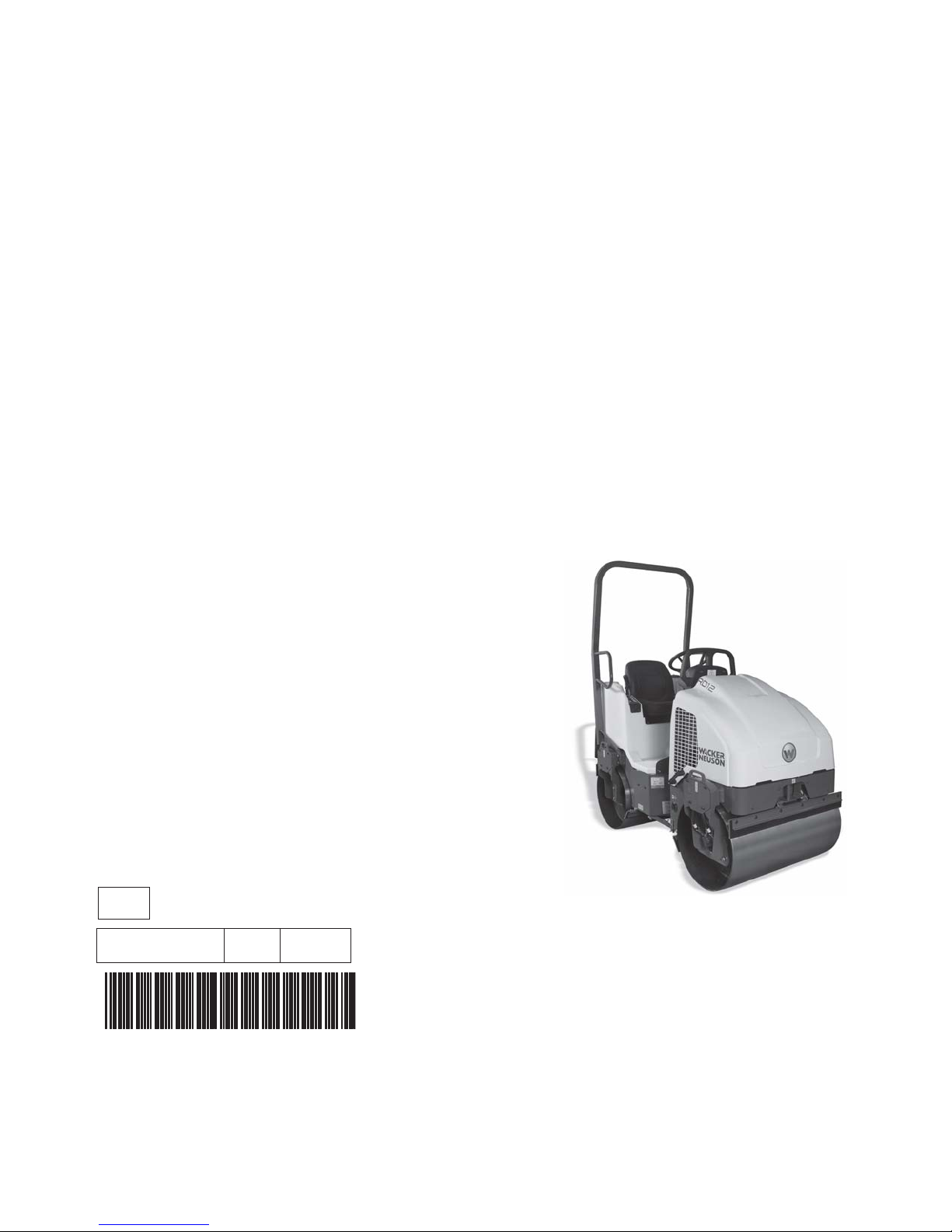
Repair Manual
Roller
RD 12
EN
5000192242 02 0912
5000192242

Copyright notice
© Copyright 2012 by Wacker Neuson Production Americas LLC
All rights, including copying and distribution rights, are reserved.
This publication may be photocopied by the original purchaser of the
machine. Any other type of reproduction is prohibited without express
written permission from Wacker Neuson Production Americas LLC.
Any type of reproduction or distribution not authorized by Wacker
Neuson Production Americas LLC represents an infringement of valid
copyrights. Violators will be prosecuted.
Trademarks
Manufacturer
Original instructions
All trademarks referenced in this manual are the property of their
respective owners.
Wacker Neuson Production Americas LLC
N92W15000 Anthony Avenue
Menomonee Falls, WI 53051 U.S.A.
Tel: (262) 255-0500 · Fax: (262) 255-0550 · Tel: (800) 770-0957
www.wackerneuson.com
This Operator’s Manual presents the original instructions. The original
language of this Operator’s Manual is American English.

RD 12/RD 12A Foreword
This manual covers machines with Item Number:
0620058, 0620320, 0620369, 0620059, 0620321
Operating / Parts Information
You must be familiar with the operation of this machine before you
attempt to troubleshoot or repair it. Basic operating and maintenance
procedures are described in the Operator’s Manual supplied with the
machine. Keep a copy of the Operator’s Manual with the machine at all
times. Use the separate Parts Book supplied with the machine to order
replacement parts. If you are missing either of the documents, please
contact Wacker Neuson Corporation to order a replacement.
Damage caused by misuse or neglect of the unit should be brought to
the attention of the operator to prevent similar occurrences from
happening in the future.
This manual provides information and procedures to safely repair and
maintain the above Wacker Neuson model(s). For your own safety and
protection from injury, carefully read, understand, and observe all
instructions described in this manual. THE INFORMATION
CONTAINED IN THIS MANUAL IS BASED ON MACHINES
MANUFACTURED UP TO THE TIME OF PUBLICATION. WACKER
NEUSON CORPORATION RESERVES THE RIGHT TO CHANGE
ANY PORTION OF THIS INFORMATION WITHOUT NOTICE.
wc_tx000663gb.fm 3

Foreword RD 12/RD 12A
CALIFORNIA
Proposition 65 Warning:
Engine exhaust, some of its constituents, and certain vehicle
components, contain or emit chemicals known to the State of
WARNING
California to cause cancer and birth defects or other reproductive
harm.
All rights, especially copying and distribution rights, are reserved.
Copyright 2009 by Wacker Neuson Corporation
No part of this publication may be reproduced in any form or by any
means, electronic or mechanical, including photocopying, without
express written permission from Wacker Neuson Corporation.
Any type of reproduction or distribution not authorized by Wacker
Neuson Corporation represents an infringement of valid copyrights,
and violators will be prosecuted. We expressly reserve the right to
make technical modifications, even without due notice, which aim at
improving our machines or their safety standards.
wc_tx000663gb.fm 4

RD 12/RD 12A Table of Contents
1 Safety Information 9
1.1 Operating Safety ................................................................................ 10
1.2 Operator Safety while using Internal Combustion Engines ................ 12
1.3 Service Safety .................................................................................... 13
1.4 Label Locations .................................................................................. 15
1.5 Safety and Operating Labels .............................................................. 16
2 Operation 22
2.1 Operation and Service Locations ....................................................... 22
2.2 Control Panel ...................................................................................... 24
2.3 Vibration ............................................................................................. 26
2.4 Water Spray System .......................................................................... 27
2.5 Starting ............................................................................................... 28
2.6 Stopping/Parking ................................................................................ 30
2.7 Auxiliary Battery Positive Terminal ..................................................... 31
3 Honda Engine Starting System 32
3.1 Checking the 20A Main Fuse ............................................................. 33
3.2 Checking Wiring to the Starter Solenoid & Anti-backfire Solenoid ..... 34
3.3 Checking the Key Switch .................................................................... 36
3.4 Checking the Crank Relay .................................................................. 37
3.5 Checking the Neutral Switch .............................................................. 38
3.6 Checking the Neutral Relay ................................................................ 39
4 Wacker Neuson Engine Starting System 40
4.1 Checking the 20A Main Fuse ............................................................. 41
4.2 Checking the Wiring to the Starter Solenoid & Anti-backfire Solenoid 42
4.3 Checking the Key Switch .................................................................... 43
4.4 Checking the Crank Relay .................................................................. 44
4.5 Checking the Neutral Switch .............................................................. 45
4.6 Checking the Neutral Relay ................................................................ 46
5

Table of Contents RD 12/RD 12A
5 Drive System 48
5.1 Checking the Tow Valve ......................................................................49
5.2 Adjusting the Drive Control Cable .......................................................50
5.3 Checking the Drive System Operating Pressure .................................51
5.4 Checking the Drive System Relief Pressure .......................................52
5.5 Checking Drive Motors for Binding ......................................................53
5.6 Checking Oil Flow through the Drive Motors .......................................55
6 Vibration System and Steering 56
6.1 Checking the Engine Speed and Vibration Speed ..............................57
6.2 Troubleshooting a System that Vibrates Poorly ..................................58
6.3 Checking the Vibration Solenoid Valve ...............................................60
6.4 Checking the Vibration Switch .............................................................61
7 Steering System 62
7.1 Checking the Steering System Hydraulic Pressure .............................62
7.2 Troubleshooting the Steering System .................................................63
8 Spray System 64
8.1 Troubleshooting the Spray System .....................................................64
8.2 Checking Power to the Spray Bar Pump .............................................65
8.3 Checking the Pump Timer Module ......................................................66
8.4 Checking the Spray System Switch ....................................................67
9 Disassembly & Assembly 68
9.1 Tools Required for Disassembly/Assembly Procedures .....................68
9.2 Information Regarding Replacement Parts .........................................68
9.3 Information Regarding Reference Numbers ( ) ...................................68
9.4 Information Regarding Threadlocking Compounds .............................68
9.5 Removing the Articulating Joint ...........................................................69
9.6 Installing the Articulating Joint .............................................................70
wc_br0170797en_002TOC.fm 6

RD 12/RD 12A Table of Contents
9.7 Removing the Rear Drum ................................................................... 71
9.8 Installing the Rear Drum ..................................................................... 73
9.9 Removing the Brake and Brake Cable ............................................... 75
9.10 Installing the Brake and Brake Cable ................................................. 77
9.11 Removing Rear Drive Motor ............................................................... 79
9.12 Installing the Rear Drive Motor ........................................................... 81
9.13 Removing the Front Drum .................................................................. 83
9.14 Installing the Front Drum .................................................................... 85
9.15 Removing the Front Drive Motor ........................................................ 87
9.16 Installing the Front Drive Motor .......................................................... 88
9.17 Removing the Exciter ......................................................................... 89
9.18 Installing the Exciter ........................................................................... 91
9.19 Disassembling the Exciter Bearings ................................................... 93
9.20 Assembling the Exciter Bearings ........................................................ 95
9.21 Removing the Control Cable and Control Lever ................................. 97
9.22 Installing the Control Cable and Control Lever ................................... 99
9.23 Removing the Exciter Pump ............................................................. 100
9.24 Installing the Exciter Pump ............................................................... 101
9.25 Removing the Drive Pump ............................................................... 102
9.26 Installing the Drive Pump ................................................................. 103
9.27 Removing the Engine ....................................................................... 104
9.28 Installing the Engine ......................................................................... 106
9.29 Removing the Steering Valve ........................................................... 108
9.30 Installing the Steering Valve ............................................................. 110
9.31 Removing the Hydraulic Tank .......................................................... 112
9.32 Installing the Hydraulic Tank ............................................................ 114
9.33 Removing the Fuel Tank .................................................................. 116
9.34 Installing the Fuel Tank .................................................................... 118
10 Schematics 120
10.1 Hydraulic Schematic ......................................................................... 120
10.2 Hydraulic Schematic Components ................................................... 121
10.3 Electrical Schematic Identification—RD 12A .................................... 121
10.4 Electrical Schematic “A”—RD 12A ................................................... 122
10.5 Electrical Schematic “A” Components—RD 12A .............................. 123
10.6 Electrical Schematic “B”—RD 12A ................................................... 124
10.7 Electrical Schematic “B” Components—RD 12A .............................. 125
10.8 Electrical Schematic—RD 12 ........................................................... 126
10.9 Electrical Schematic Components—RD 12 ...................................... 127
7

Table of Contents RD 12/RD 12A
11 Technical Data 128
11.1 Engine ...............................................................................................128
11.2 Roller .................................................................................................129
11.3 Lubrication .........................................................................................129
11.4 Dimensions ........................................................................................130
11.5 Sound Measurements .......................................................................131
11.6 Measurements of Operator Exposure to Vibration ............................131
11.7 Hydraulic Pressures ..........................................................................132
wc_br0170797en_002TOC.fm 8

RD 12/RD 12A Safety Information
1 Safety Information
This manual contains DANGER, WARNING, CAUTION, NOTICE and
NOTE callouts which must be followed to reduce the possibility of
personal injury, damage to the equipment, or improper service.
This is the safety alert symbol. It is used to alert you to potential
personal injury hazards. Obey all safety messages that follow this
symbol to avoid possible injury or death.
DANGER indicates a hazardous situation which, if not avoided, will
result in death or serious injury.
DANGER
WARNING
CAUTION
WARNING indicates a hazardous situation which, if not avoided, could
result in death or serious injury.
CAUTION indicates a hazardous situation which, if not avoided, could
result in minor or moderate injury.
NOTICE: Used without the safety alert symbol, NOTICE indicates a
situation which, if not avoided, could result in property damage.
Note: Contains additional information important to a procedure.
wc_si000302gb.fm 9

Safety Information RD 12/RD 12A
1.1 Operating Safety
Notice: State Health Safety Codes and Public Resources Codes
specify that in certain locations spark arresters be used on internal
combustion engines that use hydrocarbon fuels. A spark arrester is a
device designed to prevent accidental discharge of sparks or flames
from the engine exhaust. Spark arresters are qualified and rated by
the United States Forest Service for this purpose.
In order to comply with local laws regarding spark arresters, consult
the engine distributor or the local Health and Safety Administrator.
Familiarity and proper training are required for the safe operation of the
machine. Machines operated improperly or by untrained personnel
can be hazardous. Read the operating instructions contained in this
WARNING
1.1.1 DO NOT drive over curbs or other uneven objects that will result in the
manual and the engine manual, and familiarize yourself with the
location and proper use of all controls. Inexperienced operators should
receive instruction from someone familiar with the machine before
being allowed to operate it.
machine and operator being shaken.
1.1.2 DO NOT attempt to start the machine when standing alongside it. Only
start the engine when seated in the driver's seat and with the forward/
reverse control in the neutral position.
1.1.3 Do not allow anyone to operate this equipment without proper training.
People operating this equipment must be familiar with the risks and
hazards associated with it.
1.1.4 Do not touch the engine or muffler while the engine is on or
immediately after it has been turned off. These areas get hot and may
cause burns.
1.1.5 Do not use accessories or attachments that are not recommended by
Wacker Neuson. Damage to equipment and injury to the user may
result.
1.1.6 NEVER leave the machine running unattended.
1.1.7 NEVER operate the machine with the fuel cap loose or missing.
1.1.8 NEVER carry passengers on the machine. Danger of crushing—keep
clear of the articulated steering joint between the front and rear frames.
1.1.9 NEVER use or attempt to repair damaged safety belts or ROPS.
Replace only with Wacker Neuson spare parts.
1.1.10 ALWAYS disengage and stow the locking bar for the articulated
steering joint before operating the machine. The machine cannot be
steered when the locking bar is engaged.
1.1.11 ALWAYS check that all controls are functioning properly immediately
after start-up! DO NOT operate the machine unless all controls operate
correctly.
wc_si000302gb.fm 10

RD 12/RD 12A Safety Information
1.1.12 ALWAYS remain aware of changing positions and the movement of
other equipment and personnel on the job site.
1.1.13 ALWAYS remain seated and wear the seat belt at all times while
operating the machine.
1.1.14 ALWAYS remain aware of changing surface conditions and use extra
care when operating over uneven ground, on hills, or over soft or
coarse material. The machine could shift or slide unexpectedly.
1.1.15 ALWAYS use caution when operating the machine near the edges of
pits, trenches or platforms. Check to be sure that ground surface is
stable enough to support the weight of the machine with operator and
that there is no danger of the roller sliding, falling or tipping.
1.1.16 ALWAYS wear protective clothing appropriate to the job site when
operating the machine.
1.1.17 ALWAYS keep hands, feet, and loose clothing away from moving parts
of the machine.
1.1.18 Read, understand, and follow procedures in the Operator’s Manual
before attempting to operate the machine.
1.1.19 Store the machine properly when it is not being used. The machine
should be stored in a clean, dry location out of the reach of children.
1.1.20 Always operate the machine with all safety devices and guards in
place and in working order.
1.1.21 ALWAYS be sure that all other persons are at a safe distance from the
machine. Stop the machine if people step into the working area of the
machine.
wc_si000302gb.fm 11

Safety Information RD 12/RD 12A
1.2 Operator Safety while using Internal Combustion Engines
Internal combustion engines present special hazards during operation
and fueling. Read and follow the warning instructions in the engine
owner’s manual and the safety guidelines below. Failure to follow the
WARNING
1.2.1 Do not smoke while operating the machine.
1.2.2 Do not smoke when refueling the engine.
1.2.3 Do not refuel a hot or running engine.
1.2.4 Do not refuel the engine near an open flame.
1.2.5 Do not spill fuel when refueling the engine.
1.2.6 Do not run the engine near open flames.
1.2.7 Do not run the machine indoors or in an enclosed area such as a deep
warnings and safety standards could result in severe injury or death.
trench unless adequate ventilation, through such items as exhaust
fans or hoses, is provided. Engine exhaust contains carbon monoxide.
This is a poison you cannot see or smell. Exposure to carbon
monoxide can cause loss of consciousness and CAN KILL YOU IN
MINUTES.
1.2.8 Refill the fuel tank in a well-ventilated area.
1.2.9 Replace the fuel tank cap after refueling.
1.2.10 ALWAYS keep the area around a hot exhaust pipe free of debris to
reduce the chance of an accidental fire.
1.2.11 ALWAYS check the fuel lines and the fuel tank for leaks and cracks
before starting the engine. Do not run the machine if fuel leaks are
present or the fuel lines are loose.
wc_si000302gb.fm 12

RD 12/RD 12A Safety Information
1.3 Service Safety
A poorly maintained machine can become a safety hazard! In order
for the machine to operate safely and properly over a long period of
time, periodic maintenance and occasional repairs are necessary.
WARNING
1.3.1 Some service procedures require that the machine’s battery be
disconnected. To reduce the risk of personal injury, read and
understand the service procedures before performing any service to
the machine.
1.3.2 All adjustments and repairs MUST be completed before operation. Do
not operate the machine with a known problem or deficiency! All
repairs and adjustments should be completed by a qualified
technician.
1.3.3 Do not attempt to clean or service the machine while it is running.
Rotating parts can cause severe injury.
1.3.4 Do not crank a flooded engine with the spark plug removed on
gasoline-powered engines. Fuel trapped in the cylinder will squirt out
the spark plug opening.
1.3.5 Do not test for spark on gasoline-powered engines if the engine is
flooded or the smell of gasoline is present. A stray spark could ignite
the fumes.
1.3.6 Do not use gasoline or other types of fuels or flammable solvents to
clean parts, especially in enclosed areas. Fumes from fuels and
solvents can become explosive.
1.3.7 Do not modify the machine without the express written approval of the
manufacturer.
1.3.8 DO NOT stand under the machine while it is being hoisted or moved.
1.3.9 DO NOT get onto the machine while it is being hoisted or moved.
1.3.10 DO NOT use the machine as a ladder. Use safe ladders and platforms
designed for this purpose.
1.3.11 DO NOT modify, weld, or drill safety frames (ROPS) fitted as original
equipment. DO NOT loosen or remove bolts. DO NOT weld, drill or
modify a broken safety frame.
1.3.12 DO NOT open the hydraulic lines or loosen the hydraulic connections
while the engine is running! Before dismantling the hydraulic
connectors or hoses, ensure that all pressure has been bled from the
circuit. Hydraulic fluid under pressure can penetrate the skin, cause
burns, blind, or create other personal injury hazards. Set all controls in
neutral, turn engine off, and allow the fluids to cool before loosening
hydraulic fittings or attaching test gauges.
1.3.13 ALWAYS check all external fasteners at regular intervals.
wc_si000302gb.fm 13

Safety Information RD 12/RD 12A
1.3.14 Keep the area around the muffler free of debris such as leaves, paper,
cartons, etc. A hot muffler could ignite the debris and start a fire.
1.3.15 Replace worn or damaged components with spare parts designed and
recommended by Wacker Neuson Corporation.
1.3.16 Disconnect the spark plug on machines equipped with gasoline
engines, before servicing, to avoid accidental start-up.
1.3.17 Keep the machine clean and labels legible. Replace all missing and
hard-to-read labels. Labels provide important operating instructions
and warn of dangers and hazards.
1.3.18 ALWAYS do periodic maintenance as recommended in the Operator’s
Manual.
1.3.19 ALWAYS turn the engine off before performing maintenance or making
repairs.
1.3.20 ALWAYS keep hands, feet and loose clothing away from moving parts.
1.3.21 ALWAYS make sure slings, chains, hooks, ramps, jacks and other
types of lifting devices are attached securely and have enough weightbearing capacity to lift or hold the machine safely. Always remain
aware of the location of other people in the area when lifting the
machine.
1.3.22 ALWAYS make sure hose connections have been reconnected back
to the correct fitting. Failure to do so may result in damage to the
machine and/or injury to person on or near the machine.
1.3.23 ALWAYS secure the articulated steering joint using the locking bar
before lifting, jacking, and servicing the machine. The machine halves
could swing together unexpectedly and cause a serious injury.
1.3.24 ALWAYS lock the lifting cylinders in the open position when the seat
pedestal is raised.
1.3.25 Before you start the machine, ensure that all tools have been removed
from the machine and that replacement parts and adjusters are firmly
tightened.
1.3.26 Fluid leaks from small holes are often practically invisible. DO NOT use
your bare hands to check for leaks. Check for leaks using a piece of
cardboard or wood.
wc_si000302gb.fm 14
RD 12/RD 12A Safety Information
1.4 Label Locations
FF
X
wc_si000302gb.fm 15
Safety Information RD 12/RD 12A
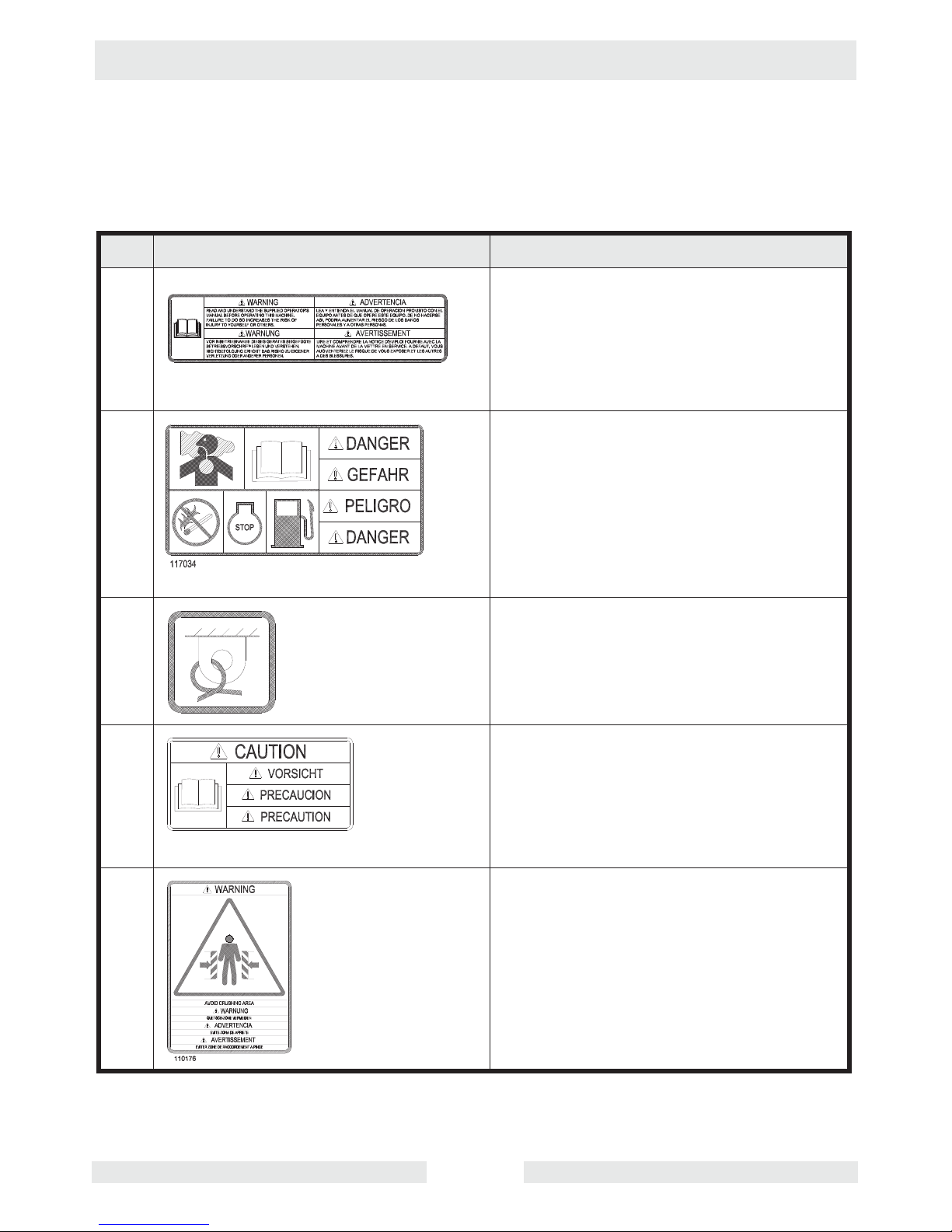
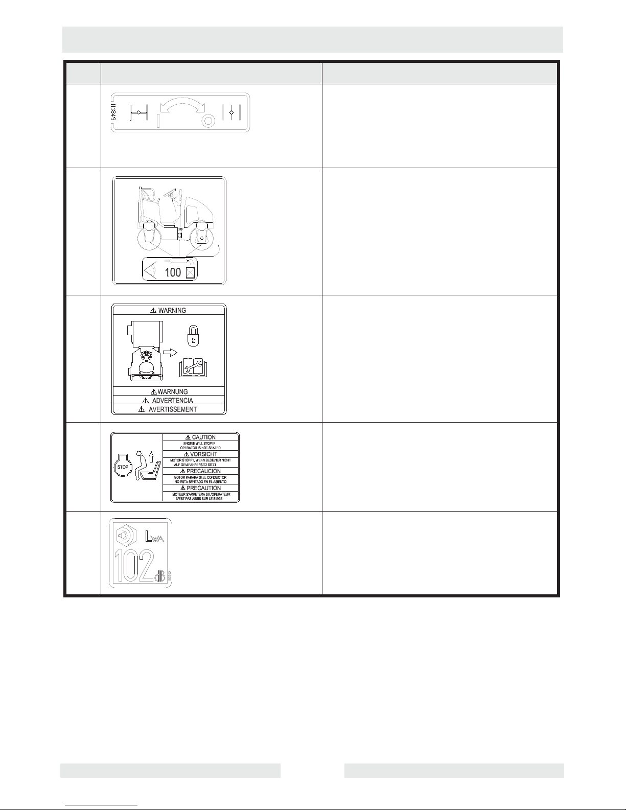
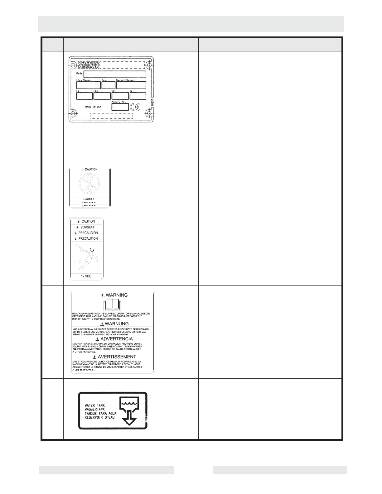
1.5 Safety and Operating Labels
Wacker Neuson machines use international pictorial labels where
needed. These labels are described below:
Ref. Label Meaning
A WARNING!
Read and understand the supplied
Operator’s Manual before operating the
machine. Failure to do so increases the
risk of injury to yourself or others.
B DANGER!
Engines emit carbon monoxide; operate
only in well-ventilated area. Read the
Operator’s Manual.
No sparks, flames, or burning objects
near the machine. Shut off the engine
before refueling.
C Tie-down point
E CAUTION!
Read and understand the supplied
Operator’s Manual before operating this
machine. Failure to do so increases the
risk of injury to yourself or others.
F WARNING!
Pinch point.
wc_si000302gb.fm 16
RD 12/RD 12A Safety Information
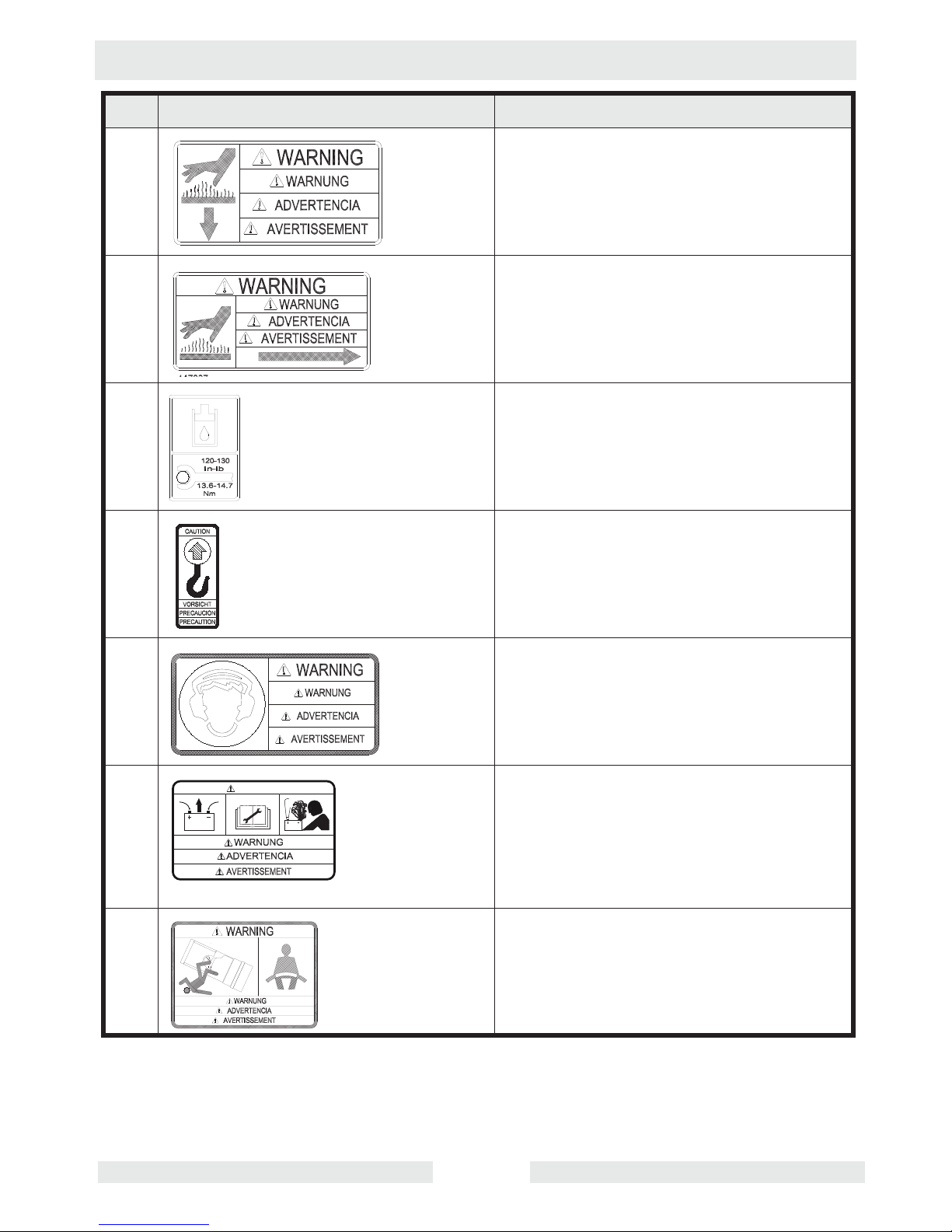
Ref. Label Meaning
G WARNING!
Hot surface!
H WARNING!
Hot surface!
I Hydraulic oil reservoir fill tube.
Torque nuts to 13.6-14.7 Nm (120-130
in.lbs.) maximum.
J CAUTION
Lifting point.
K WARNING!
To prevent hearing loss, wear hearing
protection when operating this machine.
M WARNING!
WARNING
Disconnect battery before servicing.
Read Repair Manual for instructions.
Battery contains caustic acid and
potentially explosive hydrogen gas.
N WARNING!
Always wear seat belt when operating
roller.
wc_si000302gb.fm 17
Safety Information RD 12/RD 12A
Ref. Label Meaning
T Choke:
0 = Open
l = Closed
U Grease points: Inspect and lubricate
every 100 hours of operation.
V WARNING!
Avoid crushing area.
Articulated steering joint locking location.
Lock the articulated steering joint before
servicing the machine.
Read Repair Manual.
W Engine will stop without operator seated.
X Guaranteed sound power level in dB(A).
wc_si000302gb.fm 18
RD 12/RD 12A Safety Information
Ref. Label Meaning
Y A nameplate listing the model number,
item number, revision number, and serial
number is attached to each unit. Please
record the information found on this plate
so it will be available should the
nameplate become lost or damaged.
When ordering parts or requesting
service information, you will always be
asked to specify the model number, item
number, revision number, and serial
number of the unit.
Z No lift point.
CC CAUTION! Electric shock hazard at
auxiliary battery positive terminal. Never
touch this terminal and a metal portion of
the machine simultaneously.
DD WARNING!
Read and understand the supplied
Operator’s Manual before operating the
machine. Failure to do so increases the
risk of injury to yourself or others.
EE Water tank
wc_si000302gb.fm 19

Safety Information RD 12/RD 12A
Ref. Label Meaning
FF This machine may be covered by one or
more patents.
wc_si000302gb.fm 20

RD 12/RD 12A Safety Information
Notes
wc_si000302gb.fm 21

Operation RD 12/RD 12A
2 Operation
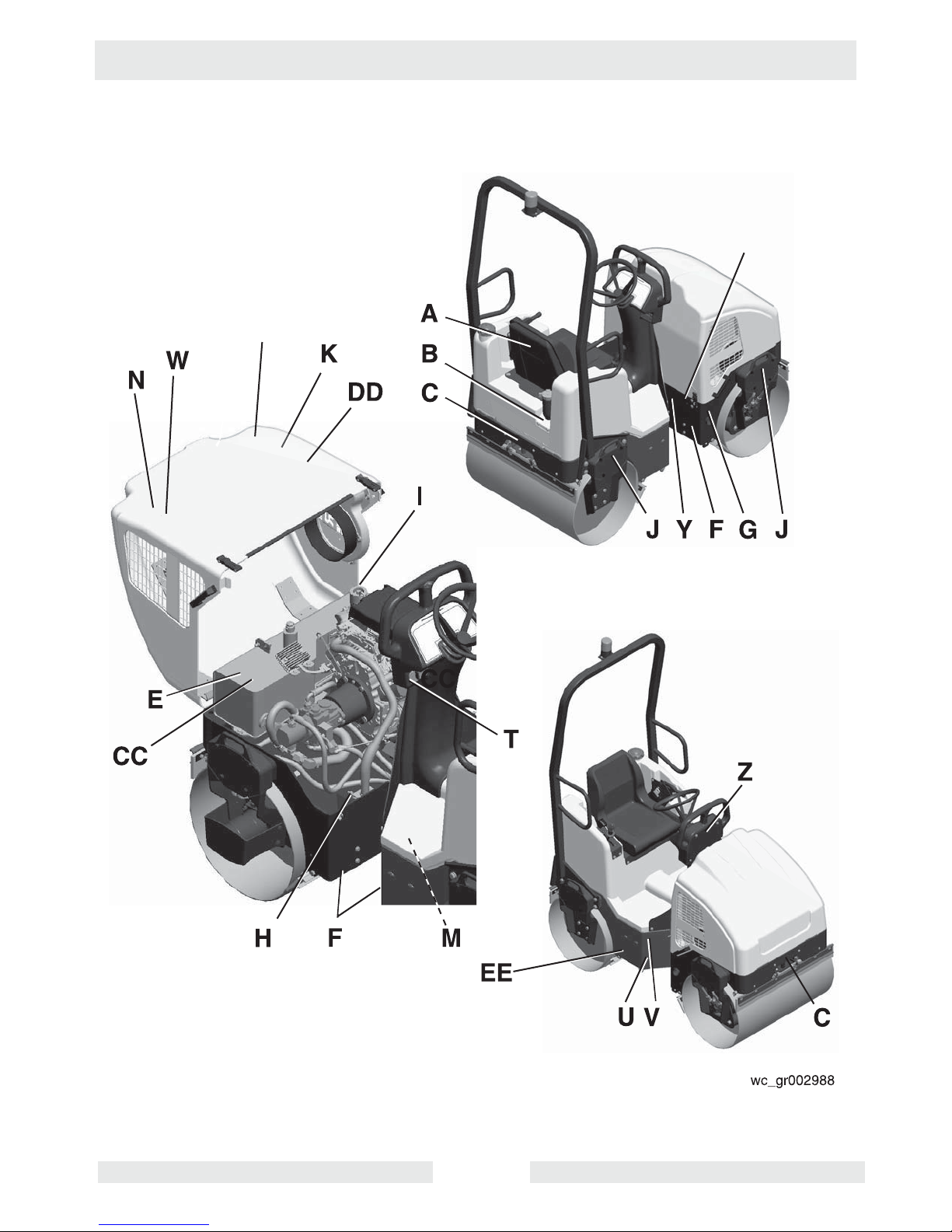
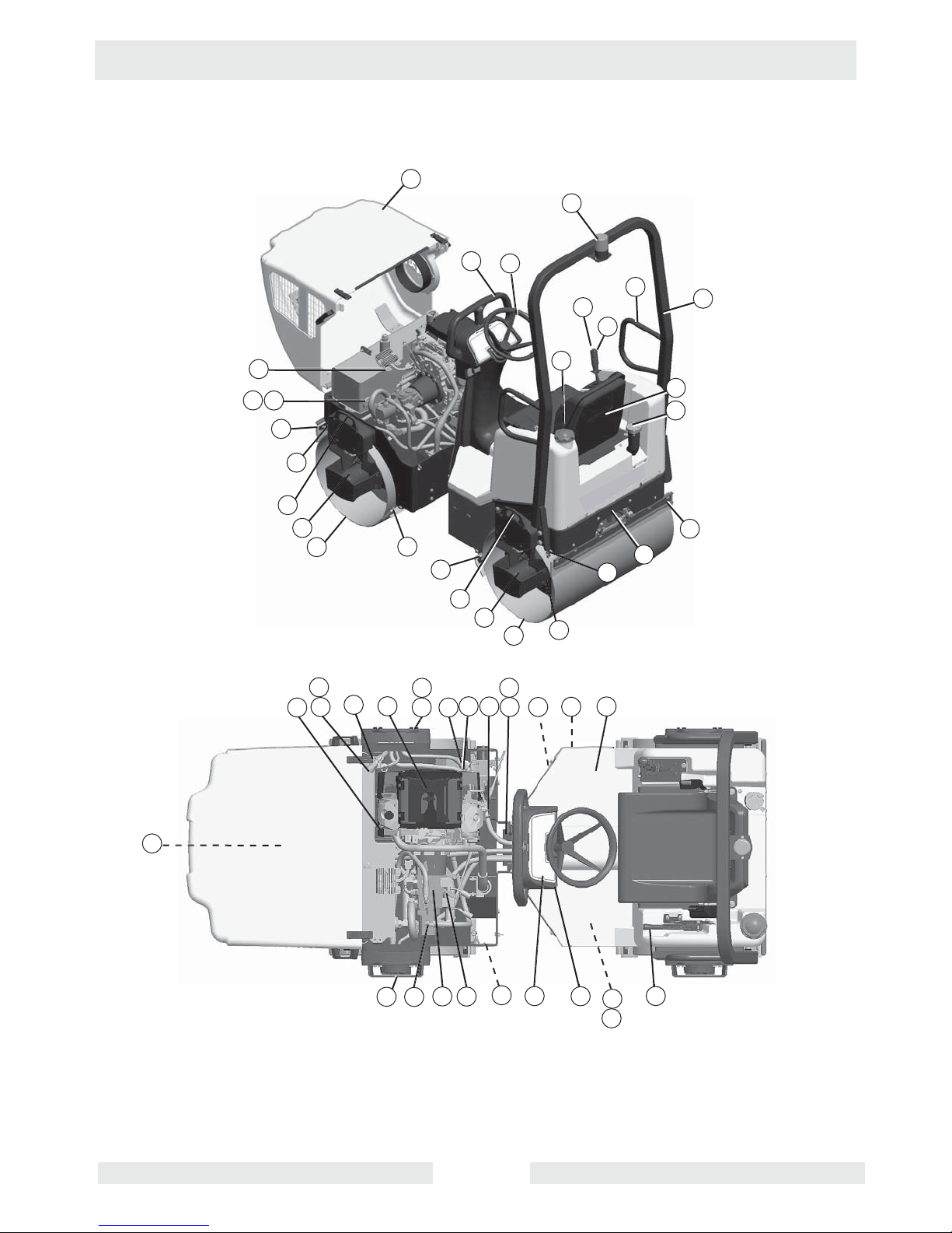
2.1 Operation and Service Locations
See Graphic: wc_gr002946
Ref. Description Ref. Description
1 Air cleaner 24 Operator’s platform
2 Articulated joint 25 Engine oil filter
3 Hand holds 26 Rear drum fill/drain plug
4 Control panel 27 Rear drum—static
5 Dipstick 28 Scraper bar (4 places)
6 Drain hose—hydraulic tank 29 Sightglass—hydraulic tank
7 Drive motor 30 Sprinkler tube (2)
8 Drive pump 31 Steering wheel
9 Engine hood 32 Steering cylinder (under floor panel)
10 Vibration control button 33 Tiedown (2 places)
11 Exciter motor 34 Beacon light (optional)
12 Exciter/Steering pump 35 Battery (under floor panel)
13 Hydraulic filter—return line 36 Hydraulic suction line
14 Hydraulic strainer—suction line 37 Grease fitting—exciter (2 places)
15 Forward / Reverse control 38 Lifting eye (4 places)
16 Front drum—vibratory 39 ROPS
17 Fuel tank fill cap 40 Seat with seatbelt
18 Fuel filter 41 Water drain
19 Grease fittings—articulated joint (4
42 Parking brake
places)
20 Hydraulic tank fill port 43 Tow valve
21 Hydraulic manifold block 44 Choke lever
22 Water tank fill cap 45 Auxiliary battery positive terminal
23 Lockarm - ---
wc_tx000865gb.fm 22
RD 12/RD 12A Operation
9
34
3
31
3
10
15
39
14
45
36
28
38
30
22
40
17
7
16
20
29
13
5
28
28
38
7
18
19
25
37
1
11
21
27
2
26
23
41
30
24
28
33
33
wc_tx000865gb.fm 23
37
12
43
6
8
44
4
32
35
42
wc_gr002946
Operation RD 12/RD 12A
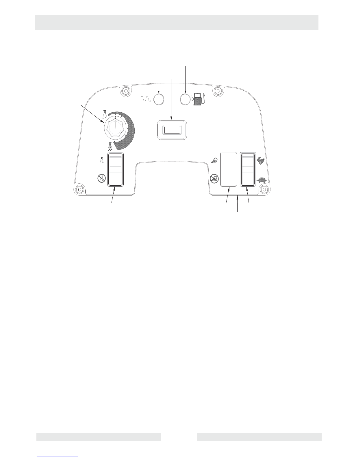
2.2 Control Panel
See Graphic: wc_gr004114
Ref. Description Ref. Description
47 Hour meter 55 Ignition switch
50 Vibration ON indicator 56 Low fuel indicator
53 Lights switch - ON and OFF
61 Water spray switch - ON and OFF
(if equipped)
54 Throttle switch - HIGH and LOW 62 Water spray dial
wc_tx000865gb.fm 24
RD 12/RD 12A Operation
62
61
50
47
56
53
54
55
wc_gr004114
wc_tx000865gb.fm 25
Operation RD 12/RD 12A
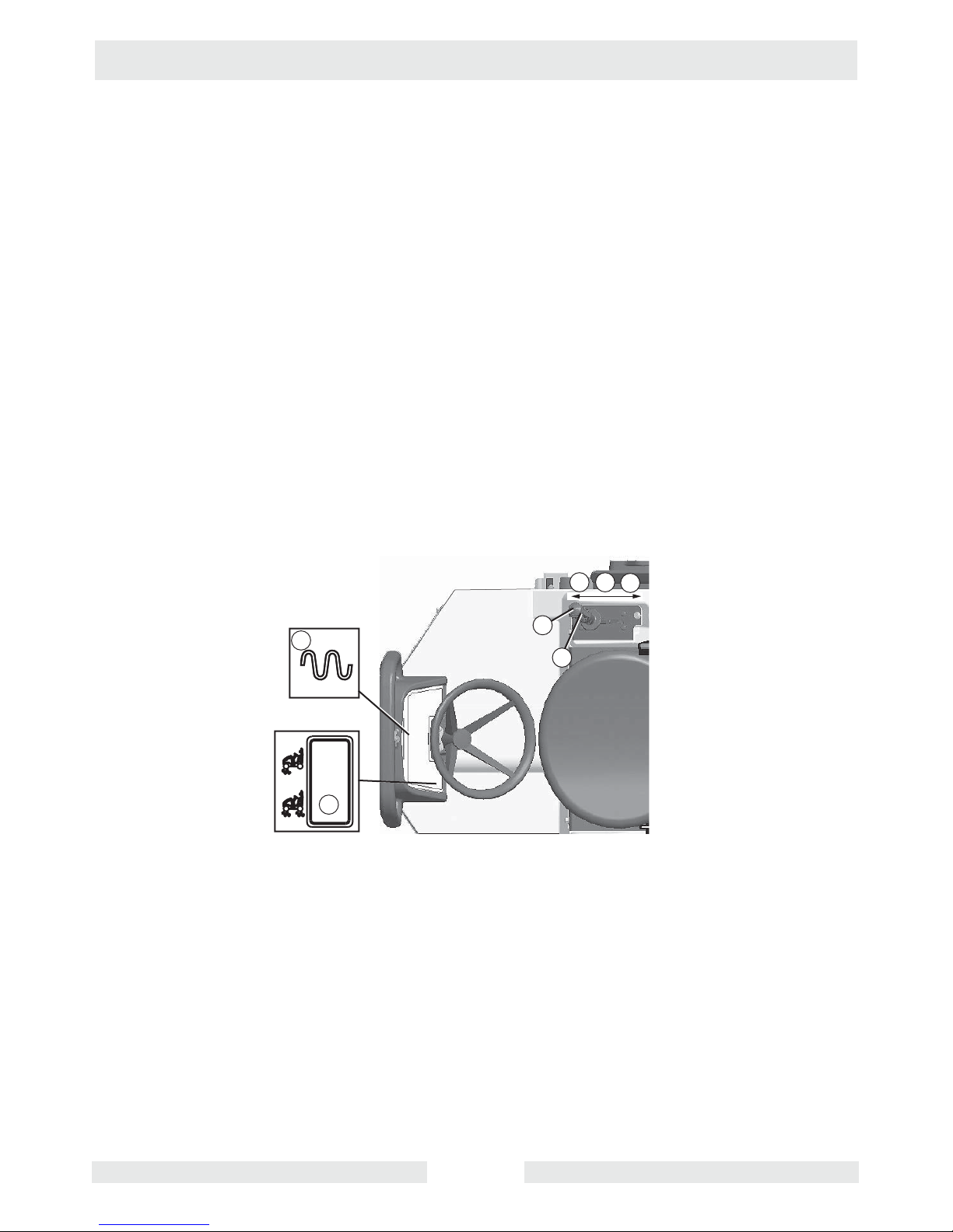
2.3 Vibration
See Graphic: wc_gr002955
The vibration is turned ON or OFF by a push button (10) located on the
forward/reverse control (15). Press the button to turn vibration ON;
press it again to turn it OFF. The vibration ON indicator (50) will light
when vibration is on. The vibration can be turned on while operating in
either forward or reverse and will remain on until it is turned off.
On the RD 16, select either the front drum vibration or dual drum
vibration by pressing the vibration switch (63) on the control panel.
CAUTION: If the machine has been turned off with the vibration on, the
vibration will come on as soon as the machine is restarted. Therefore,
for easier starting and to keep the surface finish smooth, be ready to
switch vibration off should it come on while cranking the engine.
Note: The vibration will remain on even when the forward/reverse
control (15) is in NEUTRAL. When operating on asphalt and in order
to keep the surface finish smooth, turn the vibration off before stopping
the roller.
50
63
10
15
wc_gr002955
N
F
R
wc_tx000865gb.fm 26
RD 12/RD 12A Operation
2.4 Water Spray System
See Graphic: wc_gr002946, wc_gr003638
Water from the tank is fed to the spray bars by an electric pump. The
flow of the water is controlled by a switch and a rotary dial.
Press the upper half of the water spray switch (61) to turn the water
pump on. Turn the water spray dial (62) clockwise to increase the
spray frequency. Turn the water spray dial counter-clockwise to
decrease the spray frequency. Press the lower half of the water spray
switch (61) to turn the water pump off.
Only use clean water. Dirty water, even when filtered, will rapidly clog
the tubes of the spraying equipment.
During winter, or when temperatures drop to below 0°C (32°F), drain
the water tank and spraying equipment. Run the water pump to
remove excess water from the system. Drain the water through the
water drain plug (41) located near the bottom of the rear frame,
through the sprayer end plugs, and the water filter. Freezing water may
cause broken hoses, filters and water pumps and may deform the
water tank.
62
61
wc_gr003638
wc_tx000865gb.fm 27

Operation RD 12/RD 12A
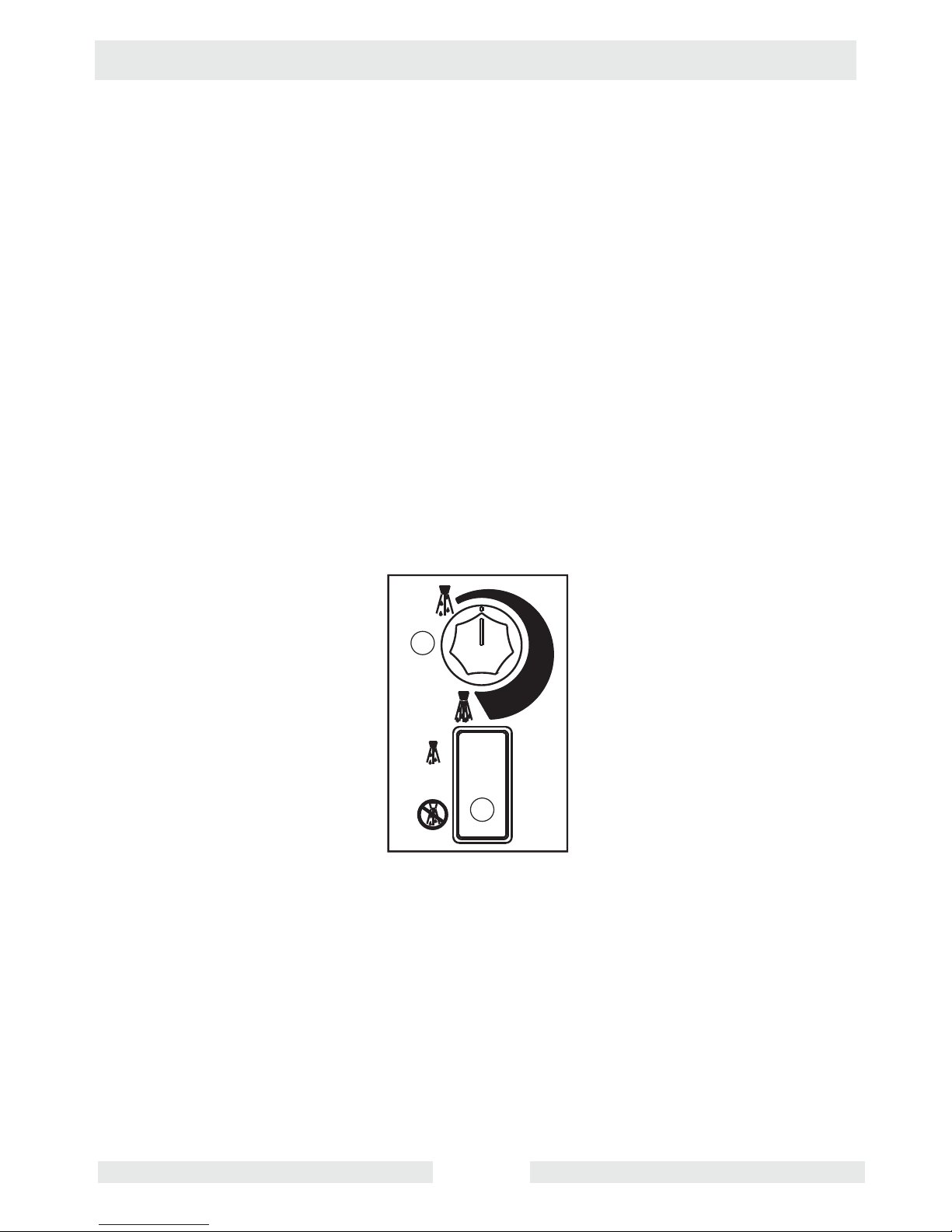
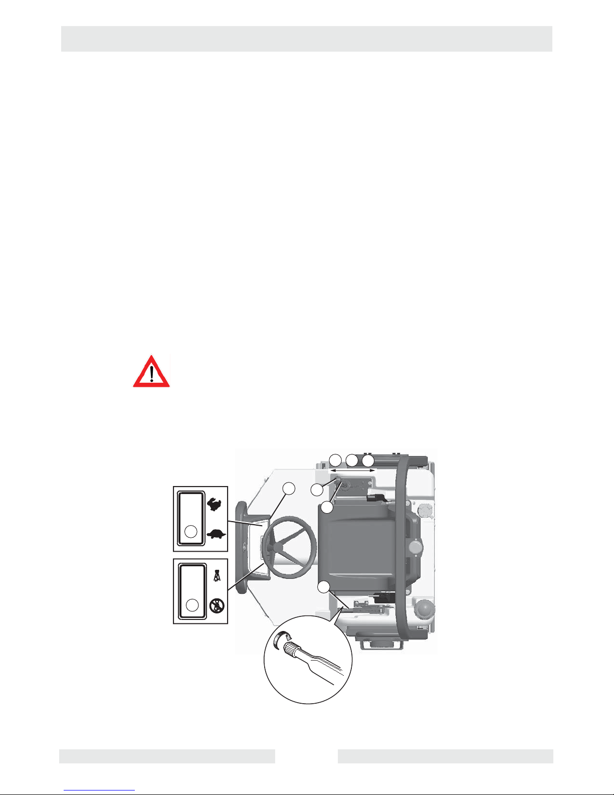
2.5 Starting
See Graphic: wc_gr002951
Exhaust gases are toxic. Do not start the engine in an enclosed space.
WARNING
2.5.1 Sit down in the operator’s seat and fasten the seat belt.
2.5.2 Set the forward/reverse control (15) in the neutral position.
2.5.3 If the engine is cold, move the choke lever (44) to the left into the
CLOSED position. If the engine is warm, move the choke control to the
right in the OPEN position.
Note: The roller will not start unless the forward/reverse control is in
the NEUTRAL position.
2.5.4 Check that the parking brake (42) is set. To set the brake, pull the
brake lever up until the brake pad engages the drum. To release the
brake lever, lower the lever. Always set the parking brake before
leaving the machine.
2.5.5 Turn the ignition switch (55) to start the engine. If the vibration indicator
light (50) is on, turn the vibration off by pressing the vibration control
button (10).
NOTICE: Do not crank the engine starter for more than 15 seconds at
one time. Longer cranking cycles could lead to starter damage.
Note: The ignition switch has an anti-rest art feature. If the engine does
not start, the switch will need to be turned to the OFF position before it
will allow the engine to be cranked again.
2.5.6 Gradually place the choke lever in the OPEN position as the engine
warms up. Allow the engine to warm up for a few minutes before
operating the roller.
2.5.7 Before moving the machine, release the parking brake by lowering the
brake lever.
2.5.8 Quickly press and release the upper half of the throttle switch (54) to
bring the engine to high throttle.
Prolonged exposure to high noise levels can damage your hearing.
Wear appropriate hearing protection while operating the roller.
WARNING
wc_tx000865gb.fm 28
RD 12/RD 12A Operation
N
54
44
55
F
10
15
42
R
wc_gr002951
wc_tx000865gb.fm 29
Operation RD 12/RD 12A
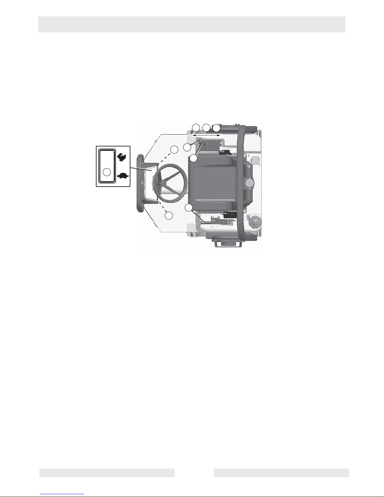
2.6 Stopping/Parking
See Graphic: wc_gr002953
2.6.1 Stop the machine on a flat surface with a suitable load bearing
capacity.
2.6.2 Turn the vibration off by pressing the vibration control button (10) on
the forward/reverse lever (15).
2.6.3 Press the water spray switch to the OFF position (61).
2.6.4 Set the forward/reverse control (15) to the NEUTRAL position.
2.6.5 Return the engine throttle to idle by pressing the lower half of the
throttle switch (54) and allow the engine to cool down.
2.6.6 Set the parking brake (42). To set the parking brake, pull the brake
lever up until the brake pad engages the drum. To release the brake,
lower the brake lever. Always set the parking brake before leaving the
machine.
Note: The parking brake engages the rear drum only.
2.6.7 Stop the engine by turning the ignition switch (55) to the OFF position.
If the vehicle constitutes a hazard or obstacle to traffic when parked, it
should be marked with signs, lights, and other warnings.
WARNING
If the machine must be parked on a sloping surface, chock the drums
with wedges to prevent any vehicle movement.
N
54
61
55
F
10
15
42
R
wc_tx000865gb.fm 30
wc_gr002953
 Loading...