

Wachendorff Prozesstechnik GmbH & Co. KG
Industriestr. 7, D-65366 Geisenheim, Germany
Phone: 0 67 22 / 99 65 -20
Fax: 0 67 22 / 99 65 -78
E-Mail: wp@wachendorff.de
www.wachendorff-prozesstechnik.de
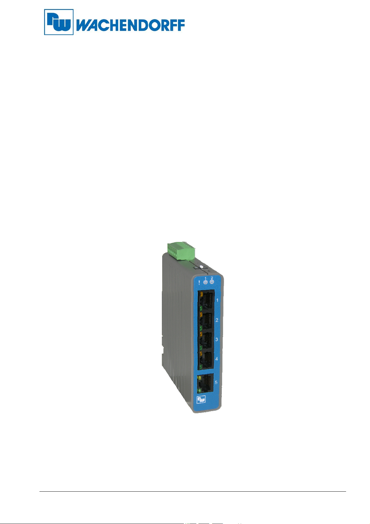
ETHSW50K
Industrial Unmanaged Fast Ethernet Switch
Operating and Installation Instructions
24.05.2019
Copyright by Wachendorff Prozesstechnik GmbH & Co KG, Industriestraße 7, D-65366 Geisenheim, Germany, Tel.: +49-6722/9965-20,
Fax: -78 All information is subject to change without notice, errors excepted.

Operating and Installation Instructions
Table of contents
1. Foreword .................................................................................................................................... 3
2. Safety instructions .................................................................................................................... 3
2.1 General information ............................................................................................................. 3
2.2 Intended Use ........................................................................................................................ 3
2.3 Qualified personnel .............................................................................................................. 3
2.4 Residual hazards ................................................................................................................. 3
2.5 Liability ................................................................................................................................. 3
2.5 CE conformity ...................................................................................................................... 3
3. Device description .................................................................................................................... 4
3.1 Specifications ....................................................................................................................... 4
4. Contents of the packaging ....................................................................................................... 5
5. Installation ................................................................................................................................. 6
5.1 Mechanical Installation ......................................................................................................... 6
5.1.1 Mounting on the DIN rail ............................................................................................... 6
5.2 Electrical Installation ............................................................................................................ 7
5.2.1 Connecting the power supply ....................................................................................... 7
5.2.2 Connection of the fail safe relay ................................................................................... 8
5.2.3
6. LED status indicators ............................................................................................................... 9
7. Configuration and settings ...................................................................................................... 9
7.1 Setting the DIP switches ...................................................................................................... 9
8. PIN assignment of the network connection ......................................................................... 10
9. Dimensions of the ETHSW50K series (in mm) ..................................................................... 11
10. Copyright ................................................................................................................................. 12
11. Exclusion of liability ............................................................................................................... 12
12. Other provisions and standards ............................................................................................ 12
13. Customer service and technical support .............................................................................. 12
Connecting the network devices ................................................................................... 8
- 2 - Stand: 24.05.2019
Operating and Installation Instructions
1. Foreword
Dear customer!
We thank you for your decision to use one of our products and congratulate you on this decision. The
Unmanaged Fast Ethernet Switch ETHSW50K from Wachendorff Prozesstechnik GmbH & Co. KG
can be used for numerous different applications. In order to make optimum use of the functional
variety of this device for you, please note the following: Every person entrusted with the
commissioning or operation of this device must have read and understood the operating
instructions and in particular the safety instructions!
2. Safety instructions
2.1 General information
To ensure safe operation, the device may only be operated in accordance with the information in the
operating and installation instructions. When used, the legal and safety regulations required for the
respective application must also be observed. This also applies analogously to the use of
accessories.
2.2 Intended Use
The ETHSW50K from Wachendorff is used to expand Ethernet networks and connect Ethernetcapable terminal devices. Any use beyond this is considered improper use.
The ETHSW50K must not be used as the sole means of averting dangerous conditions on
machines and systems. Machines and systems must be designed in such a way that faulty
states cannot lead to a situation that is dangerous for the operating personnel (e.g. by independent
limit switches, mechanical interlocks, etc.).
2.3 Qualified personnel
The ETHSW50K may only be used by qualified personnel, exclusively in accordance with the
technical data. Qualified personnel are persons who are familiar with the installation, assembly,
commissioning and operation of this device and who have a qualification corresponding to their
activity.
2.4 Residual hazards
The ETHSW50K corresponds to the state of the art and is safe to operate. The unit may present
residual hazards if used and operated improperly by untrained personnel. This manual refers to
residual hazards with the following symbol:
This symbol indicates that non-observance of the safety instructions may result
in danger to persons, serious physical injury or death and/or the possibility of
damage to property.
2.5 Liability
Liability is excluded for material and legal defects in this documentation, in particular for its
correctness, freedom from errors, freedom from third-party industrial property rights and copyrights,
completeness and/or usability - except in the case of intent or fraudulent intent.
2.5 CE conformity
The declaration of conformity is available from us. You are welcome to order them. Just call us.
- 3 - Stand: 24.05.2019
Operating and Installation Instructions
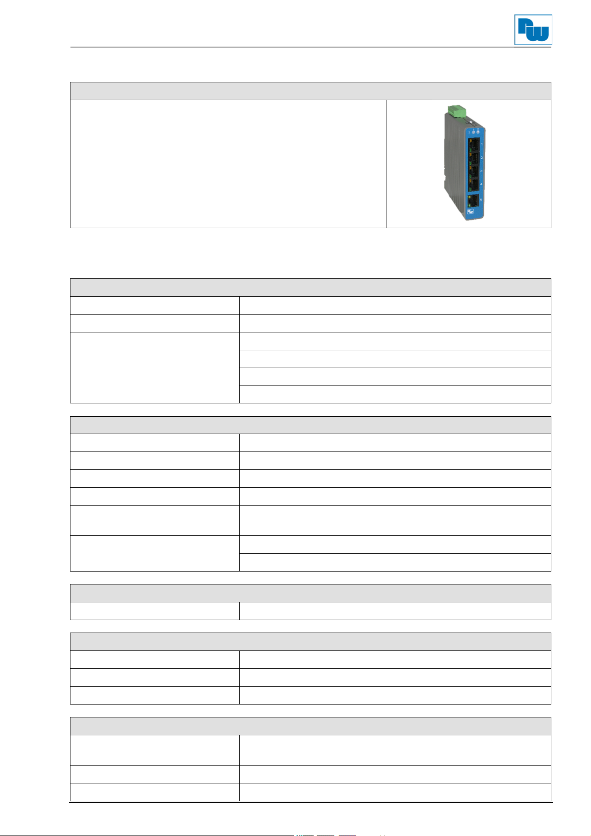
3. Device description
ETHSW50K
5 x 10/100BaseT(X)
Unmanaged / Plug and Play
IEEE 802.3, IEEE 802.3u, IEEE 802.3x
IEEE 802.3az: EEE (Energy Efficient Ethernet)
Broadcast- und Multicast-Flooding Storm Control
Redundant voltage input /
fault signal relay Output
Operating temperature -20 °C to +60 °C
Protection class IP30
3.1 Specifications
Technologies
Operating mode Store and Forward
Switching engine Wire-speed / non-blocking
Standards IEEE 802.3 (10BaseT)
IEEE 802.3u (100BaseTX)
IEEE 802.3az (EEE)
IEEE 802.3x (Full Duplex) and Back-Pressure (Half Duplex)
Interfaces
RJ45 - Ports (copper) 5x 10/100BaseT(X)
RJ45 - Speed Auto Negotiation (10/100 Mbps)
RJ45 - Duplex Half- or Full-Duplex
RJ45 - Connection MDI/MDIX Auto Crossover
Fault alarm contact Fault alarm relay for detection of power supply (normally
open, normally open, max. 1A / 24 VDC)
2 x DIP switches 1 x On/Off Power Alarm (fault signal contact) (DIP 1)
1 x On/Off Flooding Storm Control (DIP 2)
Features
MAC table size 1K
Display
1 x Alarm ALM: Power supply failure
2 x Power Status P1, P2: Power supply status
5 x Ethernet port status Link & Speed
Power supply
Execution Redundant input terminal strip plug, reverse power protection
(reverse polarity protected)
Voltage range 12 VDC to 58 VDC
Current consumption 30 mA at 48V, 25 °C, full load
- 4 - Stand: 24.05.2019

Operating and Installation Instructions
Environmental conditions
Operating temperature -20 °C to +60 °C
Storage temperature -40 °C to +85 °C
Air humidity 5 % to 95 % RH (non-condensing)
Norms and Standards
FCC/EMI FCC Part 15
CISPR 22 (EN55022), Class A
Vibration
Shock IEC60068-2-27
Free Fall IEC60068-2-32
CE (EMS) IEC61000-4-2
RoHS and WEEE RoHS (lead-free) and WEEE compliant
Housing
Degree of protection IP30
Execution
Dimensions (W x H x D) 25 mm x 113 mm x 97.38 mm
Weight 135 g
IEC60068-2-6
IEC61000-4-3
IEC61000-4-4
IEC61000-4-5
IEC61000-4-6
(Level 3)
Robust polycarbonate housing (plastic)
(with DIN rail holder)
Assembly DIN rail
4. Contents of the packaging
- Wachendorff ETHSW50K Industrial Fast Ethernet Switch unmanaged (1x)
- Terminal plug for external power supply (1x)
- Wachendorff Operating and Installation Instructions (1x)
- Device warranty card (1x)
- 5 - Stand: 24.05.2019

Operating and Installation Instructions
5. Installation
5.1 Mechanical Installation
5.1.1 Mounting on the DIN rail
The ETHSW50K is equipped with a DIN rail holder on the rear side. Please follow the steps below
for proper mounting on the DIN rail:
1. Tilt the module backwards with the top and press it onto the DIN rail. Align the
module straight.
2. Press the module down on the DIN rail until it is properly fixed on the rail. Then close
the lock on the underside by moving it upwards. The lock is correctly performed when
you hear and perceive a click.
2
Note: If the fixing clip has come loose from the holder, it must be reassembled as follows.
1
- 6 - Stand: 24.05.2019

Operating and Installation Instructions
5.2 Electrical Installation
5.2.1 Connecting the power supply
The ETHSW50K has a redundant voltage input. This ensures trouble-free operation in the event of
a power supply failure or a voltage supply failure. Please follow the steps below for proper connection:
Provide a suitable 12 to 58 VDC power source and connect it by tightening the screws
to the 6-pole terminal plug at the terminals provided for this purpose:
o P1: Primary power supply (+ / -)
o P2: Secondary power supply (+ / -)
Check the two power LEDs P1 and P2 on the device. The LEDs light up when a
connected power supply is active. The switch is ready for operation.
Warning: Before connecting the switch to the DC voltage, make sure that it complies with
the specifications.
P1
P2
Clamp P1 + P1 - P2 +
Signal
12 to 58 VDC 0 V 12 to 58 VDC
+
‐
A
L
M
+
‐
P2 -
0 V
- 7 - Stand: 24.05.2019

Operating and Installation Instructions
5.2.2 Connection of the fail safe relay
In addition to the redundant voltage input, the ETHSW50K has a fault signal relay for signalling a
fault. This ensures trouble-free operation and direct fault detection in the event of a power supply
failure or voltage supply failure. The fault signal relay is designed as a normally open contact.
For proper connection, please follow these steps:
Connect the corresponding signalling system to the connection terminals marked ALM (in the
middle of the 6-pole terminal plug, max. 1 A / 24 VDC).
Activate the fault message contact Power Alarm at PIN 1 of the DIP switch (ON).
P1
P2
+
‐
A
L
M
2
1
+
‐
Clamp ALM ALM DIP PIN 1
Connection to alarm
system
ON
Signal
Connection to alarm system
5.2.3 Connecting the network devices
The ETHSW50K has 5 x 10/100 Mbit/s ports with RJ45 connectors. At each port there are 2 LEDs
for signalling the operating mode (see chapter "6. LED status indicators"). Proceed as follows to
ensure proper functioning:
Connect your Ethernet network devices to your Fast Ethernet Switch using a
straight-through (standard patch cable) or cross-over (UTP Unshielded Twisted pair
/STP Shielded Twisted Pair) cable with RJ-45 connectors.
An LED associated with the port lights up after a successful link up depending on the
negotiated data rate.
The LED associated with the port flashes when data transmission is in progress.
- 8 - Stand: 24.05.2019

Operating and Installation Instructions
6. LED status indicators
There are three LED status indicators on the front panel of the ETHSW50K. In addition, each
RJ-45 port has 2 LED status indicators.
LED Indicator/Colour Description
P1
P2
Alarm
RJ-45 Ports
Port 1 to 5
Link/Activity
RJ-45 Ports
Port 1 to 5
Speed
On / green Primary power supply is active
Off Primary power supply not available
On / green Secondary power supply is active
Off Secondary power supply is not available
On / red Power supply failure
Off No power supply failure
On / green Ethernet link established (link up) / no data transmission
Flashing green Ethernet link established (link up) / data transmission
Off Ethernet link not established (link down)
On / yellow Ethernet link with 100 Mbit/s established
Off Ethernet link with 10 Mbit/s established or Ethernet link
7. Configuration and settings
(if power alarm is activated)
(if power alarm is activated)
not established (link down)
The ETHSW50K is an unmanaged and plug-and-play switch. The switchable Flooding Storm Control
function protects against unwanted allocation of the available transmission rate by Broad or Multicast
data frames. In addition, the ETHSW50K has a redundant voltage input and a fault relay for signalling
the fault of a power supply unit or a power supply.
7.1 Setting the DIP switches
Display
PIN 1 On Fault alarm contact Power Activate alarm
off Fault alarm contact Power Deactivate alarm
PIN 2 On Activate Flooding Storm Control
off Deactivate Flooding Storm Control
- 9 - Stand: 24.05.2019

Operating and Installation Instructions
8. PIN assignment of the network connection
RJ-45 to RJ-45, straight-through cable
PIN 1 2 3 4 5 6 7 8
Signal Tx + Tx Rx+ Rx
RJ-45, cross-over cable
PIN 1 2 3 4 5 6 7 8
Signal Rx+ Rx Tx + Tx
- 10 - Stand: 24.05.2019

Operating and Installation Instructions
9. Dimensions of the ETHSW50K series (in mm)
90,05
25,00
7,33
113,00
4,50
97,38
- 11 - Stand: 24.05.2019

Operating and Installation Instructions
10. Copyright
This document is the property of Wachendorff Prozesstechnik GmbH & Co.KG. Copying and
duplication are prohibited without prior permission. The contents of this documentation refer to the
device described therein.
11. Exclusion of liability
All technical content within this document is subject to change without notice. The content of the
document is the content of a recurring revision.
In the event of loss due to fire, earthquake, intervention by third parties or other accidents, or
intentional or accidental misuse or abuse, or use under abnormal conditions, repairs will be charged
to the user. Wachendorff Prozesstechnik is not liable for any accidental loss resulting from the use
or non-use of this product, such as loss of business profits.
Wachendorff Prozesstechnik is not liable for the consequences of improper use.
12. Other provisions and standards
FCC Conditions
This equipment has been tested and found to comply with Part 15, Class B of the FCC
Rules. Operation is subject to the following two conditions:
(1) This equipment may not cause harmful interference, which can cause harmful
interference to radio or television reception.
(2) This device must accept any interference received, including interference caused by undesired
operation.
WEEE Information
Disposal of old electrical and electronic equipment (valid in the European Union and other
European countries with separate collection system). This symbol on the product or on the
packaging means that this product must not be treated as household waste. Instead, this
product should be taken to the appropriate disposal point for recycling electrical and electronic
equipment. If the product is disposed of correctly, you help to prevent negative environmental
influences and damage to health that could be caused by improper disposal. The recycling of
materials will preserve our natural resources. For more information about recycling this product,
please contact your local Citizen Office, your household waste collection service or the store where
you purchased this product.
13. Customer service and technical support
For technical questions you can reach us under:
Industriestraße 7 - 65366 Geisenheim, Germany
Phone: +49 6722 9965-966
Fax: +49 6722 9965-78
E-mail: eea@wachendorff.de
Homepage: www.wachendorff-prozesstechnik.de
- 12 - Stand: 24.05.2019
 Loading...