


TCE I / II
Central Electronic in
Trailers
815 000 375 3
2nd Edition
This publication is not subject to any update service.
New versions are available in INFORM at
www.wabco-auto.com
815 000 329 3
8150003293
© 2007 WABCO
Vehicle Control Systems
The right of amendment is reserved
Version 002/11.03(en)
8150100303 815 010 030 3

Table of contents
1 Objective
1.1 Concept and Implementation 4
2 General
2.1 External Communication Possibilities 5
2.2 Standards 6
3 Line connection Description
3.1 Functional overview 7
3.2 Electronics 446 122 00. 0 8
3.2.1 TCE top view with connector coding 9
3.3 System connections 10
4 Cable Overview 22
4.1 TCE connection system with connecting cable and PIN connection 15
4.1.1 Overview of plug-in connectors and corresponding cables 15
5 System Functions (acc. to terminals)
5.1 Brake lining wear indicator 37
5.2 Electrical Supply 39
5.2.1 Standardised motor vehicle plug-in connections 39
5.2.2 Supply 40
5.3 Diagnosis mode and warning light function 41
5.3.1 Gateway ISO 7638 / ISO 12098 Trailer data bus 41
5.3.2 warning light function 42
5.4 Freely programmable I/O (special modules) 42
5.4.1 Monitoring functions 42
5.5 Trailer EBS and RGE connection 42
5.5.1 Trailer EBS 42
5.5.2 RGE connection 43
5.6 Rear underdrive protection terminal 44
5.7 Ramp approach help 44
5.8 Paver brake 46
5.9 Electronically controlled air suspension (ECAS) in TCE 46
5.9.1 Components 47
5.9.2 Distance sensor(s) and trailer battery 51
5.10 Pneumatic components and installation instructions 57
6 Commissioning and Diagnosis 82
6.1 Commissioning and Diagnosis 59
6.1.1 The Calibration Process 59
7 PC - Diagnosis 23
7.1 Start- and diagnostic menu 62
7.2 Vehicle definition 63
7.2.1 Chassis & lighting 64
7.2.2 Special parameters 65
7.2.3 ECAS parameters 66
7.3 Special parameters 67
7.4 Axle load calibration 72
7.5 Switch positions / Outputs 72
7.6 Service management 73
7.7 System plate 73
7.8 End Of Line - Protocol 74
8. Annex 77
8.1 Abbreviations 78
8.2 Overview of Outline Drawings 79
2

Objective
TCE
1
In modern motor vehicles the onboard information for
drivers becomes more and more extensive. In future
drivers will be able to read information about truck and
trailer via a display on their dashboard They will get this
information via data buses, i.e. via communication
connections between different electronics having a CAN
interface. As a result the connected electronic systems
will be able to exchange, evaluate and further process
information. In future lighting on vehicles will also be
controlled via data buses and errors will be displayed in
trucks.
Trailers will be included in this exchange of information
via a 7-pin ABS/EBS plug connection acc. to ISO 7638
and in parallel via a 15-pin plug connection acc. to
ISO 12098. In both cases the data connection
corresponds to ISO 11992 part 1.
By a consequent use of the available data connections
between motor vehicle and trailer WABCO creates the
precondition for new innovative vehicle functions while
at the same time the number of the required electrical
connections is limited.
In summary the objectives are as follows:
System data bus in trailers
Integration of trailers into the motor vehicle
system
• Limitation of number of electrical connections
• Extension of the motor vehicle system functions
to trailers
Integration of trailer system functions
• Level control and lifting axle control
• Ramp approach help
• Lighting control
• Telematic connection
• Additional functions
TCE II
Modifications due to the introduction of TCE II are
marked in the following text in expanded type.
• New trailer system functions via data exchange
• More simple realisation of current system
functions
Telematics
Power 7 Pin ISO 7638
Power 15 Pin ISO 12098
IVTM - Integrated
Vehicle Tire
Monitoring system
TCE
ECAS
wear
Customer
functions
approach help
Lighting
Ramp
CAN
Trailer
Data
Diagnosis
EBS modulator
BUS
Brake lining
3

1
TCE
Objective
1.1 Concept and Realisation
As trailer central electronic TCE enables the
communication between motor vehicle and trailer res.
motor vehicle and trailer systems. Moreover TCE
supports the connection of intelligent individual systems
in trailers to a powerful system like in the towing vehicle.
TCE itself assumes the following electronic and
electrical functions:
Electrical supply of trailer systems including battery
supply and battery charging equipment. With a trailer battery diagnostic and ramp operations are possible without a motor vehicle.
Motor vehicle - trailer communication for brake and
”running gear“ systems (ISO 7638), as well as for
general vehicle systems (ISO 12098). ”Running
gear“ means components concerning the driving
safety, e.g. chassis, tires, steering and suspension.
Trailer data bus for EBS, running gear, tire systems
and vehicle systems with separate CAN connections. As a result an exchange of electrical consumers and transmission of information via data
connection is possible.
Future central diagnostic connection for TCE and
all systems connected via CAN. Future diagnosis
from the motor vehicle is provided (e.g. via an onboard display).
Brake lining wear sensing system with up to six
sensors.
In future reading and processing of analogue and
digital information will be possible.
e.g.
Programmable inputs and outputs for recording of
switch positions and analogue values, as well as for
controlling modulators and additional lighting. Individual customer modules will be created by
WABCO. These are adjustable via diagnosis.
Integrated electronic level control (ECAS) for semi-
trailers and trailers with one or two level sensors.
Integrated electronic lift axle control with automatic
functions as traction help, load dependent lowering
/ lifting and manoeuvring aid.
Ramp approaching help with automatic braking
when backing and approaching the ramp.
Electronically secured lighting control and monitor-
ing with status reports to the motor vehicle.
tire pressure recording and tire pressure monitoring
with connected IVTM system.
Service support (operating hours counter, mileage
counter, electronic notebook, battery hours counter).
ISO 7638 (5/7-pin.)
Green warning light
ISO 12098 (15/7-pin.)
Side marking and limiting lights
Diagnostic plug EBS
ABS wheel sensors
EBS
LA-Ventil
LF-Vent i l
DSENS
EBS
ABS wheel sensors
Brake lining wear sensors
DSENS2
WSENS2
WSENS1
DSENS1
Trailer battery
Brake lining wear sensors
Ultra sonic sensors
TCE
IVTM
BAT
Ultra sonic
sensor
Diagnostic
plug TCE
Remote remote control unit
4

General
)
TCE
2
The following data can be transmitted to the motor
vehicle provided the respective system is installed:
• Axle loads:
• Tire pressure values
• Status of vehicle lighting
• Distance to ramp
• Brake lining wear
• Status of ramp approach help RAH
• Lift axle status
Under same conditions as in the motor vehicle the
following data can be transmitted to a telematic system:
• Error in lighting
• Error in RAH function
• Vehicle stopped before ramp
• Service date achieved
• Vehicle overloaded
• Red /yellow/green warning light
• Axle load
• Tire pressure values
• Error in RAH function
• Vehicle hitched/unhitched
• Battery status
• Vehicle door open/closed
• Operating hours
• Mileage
• Brake lining wear
2.1 External Communication
Possibilities
When a telematic system is connected to the TCE
location of the vehicle resp. recall of vehicle specific data
is possible.
The following transmission systems can be used:
The Global Positioning System, shortly called
GPS, enables identification of the vehicle position.
The Global System for Mobile Communication
(GSM) enables wireless data transmission. Thus
remote diagnosis will also be possible in future.
The 'Short Range Communication' is only possible
in the yard near a correspond. transmitting / receiving station.
Satellite
Satellite
GPS
Global Positioning System
Short wave
Communication
(Blue Tooth, DECT, ..)
Local Server
Carrier owner
Fleet owners
Satellite
Satellite
GSM
Global System for
Mobile Communication
(D1, D2, ...)
z
h
M
0
0
9
z
h
M
0
0
8
1
z
h
M
z
3
h
3
4
M
8
6
8
Telecommunications
Company
ISDN
Internet
(TCP/IP)
Fleet Management
Carrier Park Management
Services Provider
WWW Server
Satellite Antenna
Data
5

2
TCE
General
The different systems may be used from trucks with
trailer connection or separately on trucks and on trailers
(e.g. for cooler and service information).
Thus the carrier resp. the controller can check for
instance position of the vehicle, temperature of the
cooling system and state of the vehicle. On short term
he may have the vehicle turned around and pick up
another load. In case of vehicle problems the controller
can inform a nearby repair shop in advance about the
vehicle state and can care for spare parts if required.
Telematic problems can only be corrected by the
respective telematic manufacturer in his service
repair shops.
2.2 Standards
TCE observes the following standards:
TCE II
Telematic systems in trucks and trailers can retrieve
more special information from the TCE II.
– event and profile data
– Service schedule
– Vehicle master data
Telematic systems in trailers will automatically be
informed on additional events
– Vehicle door open/closed
– Vehicle hitched/unhitched
– Tire pressure changes
– Service intervals etc.
– ISO 11992 defines data interfaces
between motor vehicles and trailers
• Part 1: Exchange of digital data between truck
and trailer
• Part 2: Application for brake and ”running gear“
of part 1
• Part 3: Application for all further systems of part
1 which were not considered in part 2
• Part 4: Diagnosis (in preparation)
– ISO 7638, 7-pin electrical truck-trailer
connection for braking and running gear
systems
• Chassis, tires and brake
• Use for lighting, superstructure control or similar
is expressly excluded.
– ISO 12098, 15-pin electrical truck-trailer
connection for lighting and superstructure
• Lighting, conventional lifting and steering axle
control
• Electrical supply and data connection for non
braking and ”running gear systems“
– Brake directive ECE-R13
• Supply of braking and running gear equipment
• Cut-off of running gear systems / Functions at
electrical overload
6

Line connection Description
3.1 Functional overview
Note:
TCE I/II is already fully operational, when except
connection to the motor vehicle only the EBS system is
connected, i.e. Ramp approaching help, ECAS, lighting,
tire pressure control and GPS/GSM do not need to be
installed resp. connected.
Bremse / Fahrwerk
Brake/running gear
Ramp approaching help
Rampenanfahrhilfe
TCE
3
Anhänger-
Trailer
+
batterie
battery
EBS
Brake lining wear sensors
Bremsbelagverschleißsensoren
ISO 7638 (7-pol.)
ISO 7638 (7-pin)
ISO 12098 (15-pol.), alternativ 24N/S
ISO 12098 (15-pin) alternative 24N/S
Diagnose
Diagnosis
IVTM
System zur Reifendrucküberwachung
TCE
TCE-
warning light
Warnlampe
(Integrated Vehicle Tire Monitor)
RGE input and output
RGE Ein- und Ausgangs-
expansion (control box)
erweiterung
RGE CAN Expansion
RGE CAN-Erweiterung
(Telematic connection)
(Telematikanschluss)
(Bedienbox)
TCE
X11
X12
X13
X14 X34X24
X31X21
X22 X42
X32
X23 X33
X41 X61
X43 X63X53
X44 X64X54
X51
X52
Pressure sensors
U
P
U
Operating
Bedienei nheit(en)
interfaces
Wegsensor(en)
Path sensors
X62
Not
occupied
Solenoid
Magnetventile
valves
Drucksensor(en)
P
Magnetventil für
Solenoid valve
Liftachssteuerung
for Lifting axle
control
Nicht
belegt
Verteiler
Lighting/superstructure systems
Beleuchtung / Aufbausysteme
Superstructure system -CAN Expansion
Aufbausystem - CAN-Erweiterung
Superstructure -additional lighting, Additional
Aufbau - Zusatzbeleuchtung, zusätzl. elektr.
Versorgung und Ein- und Ausgänge
electrical supply and Inputs and outputs
7
3
TCE
Line connection Description
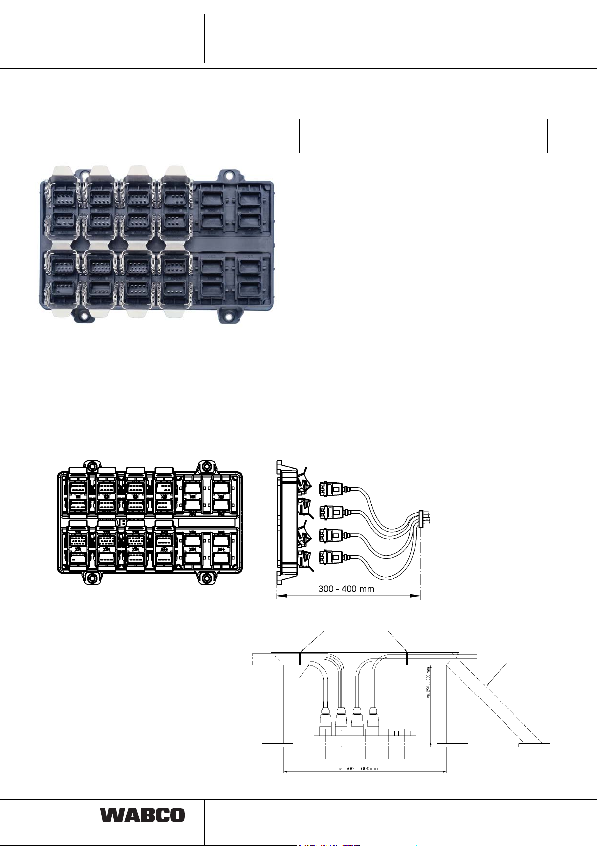
3.2 Electronic 446 122 000 0 /
446 122 001 0
Do not open the electronic remote control unit!
All terminals have to be closed.
All plug in connections are marked with an X and a
number and fitted with special locking clips. To connect
a cable, it is necessary to fold up the locking clip, push
in the plug and then close the locking clip.
Since the terminals are located very close, cables
should be plugged into the electronic in the order from
X11 to X41, X12 to X42, etc.
The front of the electronic consists of coded plug-in
terminals and thus is protected against interchange of
plugs. Unused terminals have to be closed by means of
cap 894 110 139 2.
Installation position:
Fixation to clip by means of cable binder or similar
In order to reverse the
cable back to the vehicle
frame the 45° solution
could be the better one.
Free cable
length to the
point of
fixation
approx.
300 mm
8

Line connection Description
3.2.1 TCE Top View with connector coding
TCE
3
control unit
X41-Remote remote
help
X31-Ramp approaching
X21-RGE and I/O
6 5
3 2 1
Battery
X42-Height sensor
4 3 2 1
8 7 6 5
4 3 2 1
8 7 6 5
X32-IVTM and super-
structure CAN
X22-EBS and RGE CAN
4 3 2
8 7 6
4 3 2 1
8 7 6 5
4 3 2 1
8 7 6 5
X43-Solenoid valve
lighting
X33-Superstructure
X23-Lighting
4 3 2 1
8 7 6 5
1
2
12 11
13
9 7 6
4 3
1415
10 8
5
1
2
12 11
13
9 7 6
4 3
1415
10 8
5
X44-Pressure sensor
lighting
X34-Tank vehicle
X24-Side marking
8 7 6 5
4 3 2 1
8 7 6 5
8 7 6 5
X11-Brake lining wear
1
2
12 11
13
9 7 6
4 3
7 6 5
4 3 2 1
8 7 6 5
X12-ISO 7638 (7-pin)
4 3 2 1
X13-ISO 12098 (15-pin)
1415
10 8
5
2
X14-Diagnosis and
Warning lamp
3 2 14
8
9
3
TCE
Line connection Description
3.3 System connections
TCE terminals in numeric order
1. Row
Connection X11 (optional)
Brake lining wear sensors
Connection for up to six brake lining wear sensors or up
to six wear indicators (side wire). Brake lining wear
sensors measure the thickness of the brake lining only
when braking. If wear indicators are installed, thickness
of the brake lining is actualised in braked or unbraked
condition. For example, if for all indicators 0 Volt will be
measured, connector break will be identified.
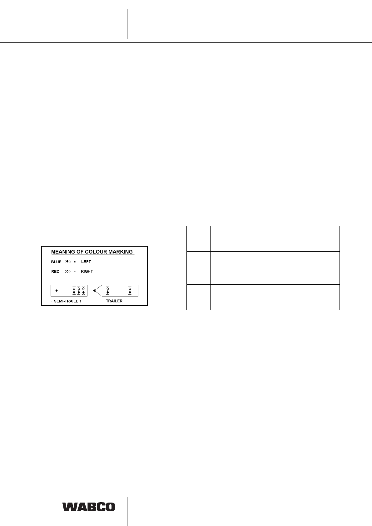
The Y cable is colour marked. Below the connector there
is a red resp. blue stripe. The red marked plug belongs
to the right vehicle side, the blue marked plug to the
left side. Furthermore the axle assignment can be found
behind the plug (L1 = 1 axle on the left).
• corresponding TCE error (e.g. failure of EBS
modulator)
• Switch on of ignition (Pin)
• Interruption of ground connection
(Pin 3 and 4).
Connection X13
Motor vehicle connection acc. to ISO 12098
(15-pin)
Connection of power supply and lighting lines with data
connection acc. to ISO 12098 (15-pin). The data bus
contains information on lighting and superstructure
systems.
Plug-in pins 10, 11 and 12 are not controlled via PC
diagnosis. These can be parameterize per PC diagnosis
by means of special modules:
Pin 10
Pin 11
Pin 12
Pin 10
Pin 11
Pin 12
Pin 10,
11, 12
Brake lining sensor
not used
Axle lift
not used / steering
axle lock
Traction help
Axle lift
not controlled
according to
ISO 12098 / 1990
according to
ISO 12098 / 2000
New standard
Standard, if no trailer
or lift axle control from
the truck desired
Connection X12
Motor vehicle connection acc. to ISO 7638
Connection motor vehicle connection 7-pins (or 5-pins,
if there is no CAN-connection) acc. to ISO 7638 with
truck-trailer data connection acc. to ISO/ 11992 part 1
and 2.
Communication truck-trailer acc. to ISO 11992.
Support of the ABS module in trucks.
Monitoring of ground connections for break
Recognition of supply under or over voltage
Recognition of overload (current and voltage
measurement) and cut-off of running gear
Systems
Active control of trailer warning light (Pin 5) at:
10
Communication truck-trailer acc. to ISO 11992.
Support of trailer recognition via flashing and/or
brake light line
Maximum input impedance ≤ 2 kOhm.
Sensing/monitoring of lighting lines
Under / over voltage recognition of electrical supply
Truck-trailer data connection acc. to ISO 11992
part 1 and 3 (only with plug connection acc. to
ISO 12098)
Freely programmable inputs and outputs (special
modules; only with plug connection acc. to
ISO 12098)
Emergency supply of EBS via brake light, if
ISO 7638 interface has failed.

Line connection Description
TCE
3
Connection X14
Diagnostic connection:
Central connection for a diagnostic tool and optional
connection for a trailer warning light (green warning
light).
Diagnostic tool connection
The electrical power is supplied from ISO 7638
Pin 30 (Pin 1). Without a towing vehicle diagnosis
is enabled with a trailer battery. Raising/lowering
per remote remote control unit is also possible in
the diagnosis mode.
Connection of a warning light
An optional green warning light can be mounted to
the vehicle.
The electrical power is supplied from ISO 7638
Pin 30 (Pin 1).
Following display info is available:
Warning light status
– flashing: Display of general TCE errors
– on: trailer vehicle not within the
normal level
– off: vehicle within normal level
and without faults or ignition
switched off.
CAN communication via trailer data bus acc. to
ISO 11898 with 250 kBaud.
In case of interferences the external CAN data con-
nections can be cut off separately.
Information to connection X23/X24/X33/X34
Trailer lighting
Vehicle lighting left/right is protected separately in the
TCE.
Note:
Errors only appear when the lighting is actuated.
Connect all lights directly to the corresponding cable.
Cables must not be shortened or lengthened!
In order to avoid malfunctions during operation, the
maximum number of consumers must be observed.
Thus installation of an additional flashing light to the
underdrive protection is not allowed! At any rate the
manufacturer specifications must be observed.
Activation, control signal and electrical supply of trailer
lighting and extension for superstructure functions are
made via plug connection acc. to ISO 12098 (15-pin).
Electronic control / protection acc. to control sig-
nals via ISO 12098.
Error detection for short circuit and interruption,
when activated.
Connection X23
2. Row
Connection X21(optional)
Extension running gear / brake
Connection of 24 V-users and/or 24 V-Sensor analysis.
Power is supplied by means of motor vehicle plug
connection acc. to ISO 7638. Functional assignment is
programmable via special modules.
Note: Since the supply is made via ISO 7638, only such
systems/components may be connected, which either
belong to the vehicle brake or belong to ”running gear“
system!
The same concerns systems/components referring to
driving security, e.g. chassis, tires, steering, suspension
Connection X22
Trailer EBS & Running Gear-Systems
Connection of Trailer EBS and of an external Running
Gear Systems.
The electrical power is supplied from ISO 7638 Pin
(pin 1) with electronic overload protection.
Standard lighting rear underdrive protection
(Performance per vehicle side)
TCE I TCE II
Brake light 21 WA 2 x 21 W
Flashing light 21 WA 2 x 21 W
Rear light 30 W 30 W
(2 x10 W Rear light +
2 x 5 W Identification
light)
Reverse
light 21 W 2 x 21 W + 2 x 70 W each
Side with freely
adjustable parameters
Rear fog
light 21W 2 x 21 W per side
with parameters
adjustable
Position
lamps 2 x 10 W 2 x 10 W or LED’s
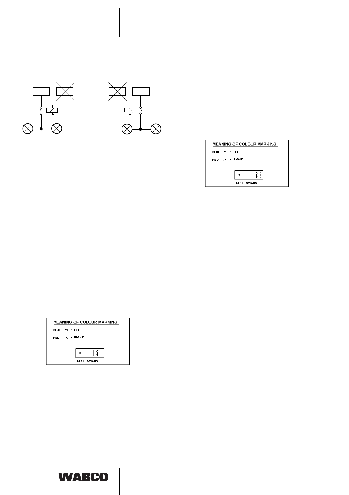
TCE I:
2 x 70 W reverse lights can be connected either to the
24 V outputs of X23 pin3 or to X33 pin 3. However, the
11
3
TCE
Line connection Description
load must only be connected to one of the plugs. A relay
is required between reverse light and the respective pin.
X23 X33 X23 X33
70 W
70 W
or
Reverse light
70 W
70 W
TCE II
Now also the connection of LED lamps to TCE II is
possible! Moreover the light failure recognition was
improved.
Via PC diagnosis the sensibility of the parameters for
cable break recognition can be set.
Standard setting: In the case of a failure of one of two
connected lights (e.g. brake light), this will not be
detected as an error.
Extended parameters: At this setting the failure of the
light with same or higher electrical power is detected.
No break recognition with light emitting diodes.
Electrical supply via separate 8 V power genera-
tion in the TCE, supplied via motor vehicle connection acc. to ISO 7638
Sending / receiving signal lines separately for each
sensor
The Y cable is colour marked. Below the connector there
is a red resp. blue stripe. The red marked plug belongs
to the right vehicle side, the blue marked plug to the
left side.
Connection X32 (optional)
Tire pressure monitoring IVTM & general vehicle
systems
Connection tire pressure monitoring and general vehicle
systems (no braking and running gear systems) with
CAN data connection.
Connection X24
Side marker lamp
The Y cable is colour marked. Below the connector there
is a red resp. blue stripe. The red marked plug belongs
to the right vehicle side, the blue marked plug to the
left side.
side marking lamps (25 W)
3. Row
Connection X31 (optional)
Ramp approaching help (RAH)
Connection of two ultrasonic sensors for measuring the
reverse distance between vehicle and ramp at backing.
General vehicle systems
Electrical supply for IVTM via ISO 7638; electrical
supply of general vehicle systems via ISO 12098
In the case of an error in the CAN communication,
it will be cut off separately (CAN connection)
Remark: Due to the electrical supply separated from
ISO 7638, the connected systems are not subject to the
overload cut-off for non braking systems.
Connection X33 (optional)
Additional lighting for superstructure like position
lamps and extensions for the superstructure
Connection of 24 V-users and/or 24 V-Sensor
analysis.
Functional assignment for freely programmable in-
puts and outputs is done via special modules of the
PC diagnosis.
12
Line connection Description
TCE
3
TCE II
Following functions may be activated via special
modules.
(Line)
normal level switch I / II PIN 7 white - green
Spring brake actuator
(ISO 11992) Pin 8 grey
Door open / closed Pin 9 white - blue
Hitched / unhitched Pin 10 white - black
normal level III / Unloading- Pin 13 red
level switch
Outputs are short circuit resp. overload protected
electrically, or by self reversion. Short circuit against
earth/power or a break is detected as error. 2 x 70 W
reverse lights can be connected either to X23 Pin 3 or
X33 Pin 3. However, the load must only be connected to
one of the plugs.
(See pict. connection X23, page 12).
Back lights (21 W)
Connection X34 (optional)
Additional lighting for tank vehicles
For high level lighting carriers with
X42: 1 or 2 level sensors (without temperature
compensation) and trailer battery
X43: Valves for 1 or 2 point control as well as lift
axle control
X44: 1 or 2 pressure sensors for axle load calcula-
tion
Connection X41
Control elements
As maximum two control elements can be connected.
By pushing button IRCU the TCE is activated (Pin 30 or
battery mode!).
For connecting two control elements a Y cable has to be
used. The Y cable is colour marked. Below the
connector there is a red resp. blue stripe. The red
marked plug leads to the second control element,
the blue marked plug to the first control element.
By means of a further plug connection between trailer
and tractor installation of a control element in the motor
vehicle is possible.
TCE I : A cable length of 25 m must not be exceeded.
TCE II : Cable lengths up to 60 m are permissible.
Brake lights (21 W)
Flashing lights (21 W)
Back lights (21 W)
The Y cable is colour marked. Below the connector there
is a red resp. blue stripe. The red marked plug belongs
to the right vehicle side, the blue marked plug to the
left side.
4. Row
Electronic level control
Electronic level control with following equipment :
X41: 1 or 2 remote control units (IRCU; Intelligent
Remote remote control unit)
Connection X42
Height sensor(s), trailer battery
A maximum of 2 height sensors can be connected to the
TCE. Here different configurations of the height sensor
arrangement are possible. This configuration is set by
means of parameters.
If only one height sensor is connected to the TCE, height
sensor 2 is active via the prefabricated cable In case of
two height sensors the plug marked with a blue
stripe is to be connected to the rear axle resp. to the
left height sensor (1
red stripe is to be connected to the front axle resp.
st
HS). The plug marked with a
13

3
TCE
Line connection Description
to the right height sensor (2nd HS). Otherwise
incorrect error display !!!
If a battery with battery box 446 156 090 0 (without
batteries), 446 156 094 0 (incl. batteries) is installed onto
the trailer, connect the prefabricated cable only.
Only lead gel accumulators may be used in the battery
box. WABCO recommend use of Panasonic LC R127R2PG lead gel accumulators, 12 V, 7,2 A.
If another box is used for the batteries, the plug of the
prefabricated cable has to be cut-off. The blue lead must
be connected to a 10 A fuse and the brown lead with the
earth pole of the battery.
Connection X43
Connection X44
Pressure sensor
TCE I:
A maximum of two pressure sensors can be connected
to the TCE. The 1
has to be connected. Among others is is used for axle
load calculation for the trailer EBS system.
st
pressure sensor (1st PS) always
TCE II
For the TCE II system it is not compulsory under certain
circumstances (dependent on the connected EBS
modulator) to connect one or two pressure sensors.
The required pressure sensor signal is directly sent from
the EBS modulator (D version) to the TCE II. If the ECAS
is to actuate a lateral or a drawbar trailer control, a
pressure sensor can be connected to the TCE.
If two pressure sensors are to be installed, the red
marked cable end is to be connected to the pressure
sensor (2
The blue marked cable end is to be connected to the
pressure sensor (1
axle.
nd
PS) to the right resp. to the front axle.
st
PS) to the left resp. to the rear
Valves 1-/2-point-control, lift axle valve
Levelling valves for semitrailers with 1- or 2- point
control (right/left), for drawbar trailers 2 point control
(front/rear). Lift axle valve(s) for one or two separately
controlled lift axle(s).
The plug marked blue leads to the lift/lower valve. The
plug marked red to the 1st lift axle valve.
14

Cable overview
4.1 The TCE plug in system with
connection cable and the
Pin assignment
Cables are supplied in different lengths. In the
following the different cable types and lengths are listed
and in column ”remark“ among others the components
to be connected. (Outline drawing see appendix).
4.1.1 Overview on terminals and the
respective cables:
Terminal X11:
Brake lining wear indicator
TCE-Electronic
TCE-Elektronik
X 11
X12 X 22 X 32 X 42 X 52 X 62
X 21 X 31 X 41 X 51 X 61
TCE
4
X 13 X 23 X 33 X 43 X 53 X 63
X 14 X 24 X 34 X 44 X 54 X 64
449 874 ...0
Used
Cable
449 874 010 0
L = 1 m
Plug
R1-2 / L1-2
R-1 „A“ +5 V 1 Brake lining
R-1 „C“ Ground 2 + 5 V
L-1 „A“ + 5 V 3 Ground
L-1 „C“ Ground 4 Brake Lining
see:
Drawing
449 874 000 0 Limit value indicator,
Assignment Plug
Remark
one axle 2x1
for PAN 17: 12480038
for PAN 19-1:
12480036 **)
Assign-
A
ment
wear R
wear L
Distributor not measurable, since with W network
**) Knorr brake to BPW axle 32480057
15

4
449 884 ... 0
TCE
Cable overview
Used
Cable
449 884 023 0
L
= 1 m
1
L
= 0.4 m
2
see:
Drawing
449 884 000 0 Limit value indicator,
Remark
two axles 2x2
for PAN 17: 12480038
for PAN 19-1:
12480036 **)
449 894 ... 0
Plug
R1-2 / L1-2
R-2 „A“ + 5 V 1 Brake lin. w. R1
R-2 „C“ Ground 5 Brake lin. w. R2
R-1 „A“ + 5 V 2 + 5 V
R-1 „C“ Ground 3 Ground
L-1 „C“ Ground 3 Ground
L-1 „A“ + 5 V 2 + 5 V
L-2 „C“ Ground 4 Brake lin. w. L1
L-2 „A“ + 5 V 8 Brake lin. w. L2
Distributor not measurable, since with W network
Used
Cable
449 894 023 0
L
= 1 m
1
L
= 0.4 m
2
449 894 043 0
L
= 1 m
1
L
= 1 m
2
Assignment PlugAAssignment
see:
Drawing
449 894 000 0 Limit value indicator,
Remark
three axles 2x3
for PAN 17: 12480038
for PAN 19-1:
12480036 **)
16
Plug
R1-3 / L1-3
R-3 „A“ + 5 V 1 Brake lin. w. R1
R-3 „C“ Ground 5 Brake lin. w. R2
R-2 „A“ + 5 V 6 Brake lin. w. R3
R-2 „C“ Ground 2 + 5 V
R-1 „A“ + 5 V 3 Ground
R-1 „C“ Ground
L-1 „A“ + 5 V
L-1 „C“ Ground 3 Ground
L-2 „A“ + 5 V 2 + 5 V
L-2 „C“ Ground 4 Brake lin. w. L1
L-3 „A“ + 5 V 8 Brake lin. w. L2
L-3 „C“ Ground 7 Brake lin. w. L3
Distributor not measurable, since with W network
Assignment PlugAAssignment

Terminal X12: Supply cable
TCE-Electronic
TCE-Elektronik
X 11
X12 X 22 X 32 X 42 X 52 X 62
X 13 X 23 X 33 X 43 X 53 X 63
X 14 X 24 X 34 X 44 X 54 X 64
X 21 X 31 X 41 X 51 X 61
449 172 ... 0
Cable overview
Used
Cable
449 172 090 0
L = 9 m
449 172 100 0
L = 10 m
449 172 120 0
L = 12 m
449 172 130 0
L = 13 m
449 172 150 0
L = 15 m
TCE
see:
Drawing
449 172 000 0 ABS/EBS
Remark
Power supply
cable
ISO 7638 (7-pin)
from
semi trailer
to motor vehicle
4
Plug A Plug B
449 272 ... 0
449 133 ... 0
Plug
A
17 red Pin 30
26black Pin 15
34yellow Ground 15
45brown Ground 30
53white Warning light
62white/green CAN H
71white/brown CAN L
Used
Cable
449 272 090 0
L = 9 m
Plug
B
see:
Drawing
449 272 000 0 ABS/EBS
Colour Assignment
Remark
Supply cable to
ISO 7638
(7-pin) from
drawbar trailer
to motor vehicle
Plug A Plug B
Used
Cable
449 133 120 0
L = 12 m
see:
Drawing
449 133 000 0 ABS/EBS
Remark
Power supply
cable with
bayonet connection
17

4
449 135 ... 0
TCE
Cable overview
Plug A Plug B
449 333 ... 0
Plug A Plug B
Used
Cable
449 135 005 0
L = 0,5 m
Plug
A
17 red Pin 30
26black Pin 15
34yellow Ground 15
45brown Ground 30
53white Warning light
62white/green CAN H
71white/brown CAN L
Used
Cable
449 333 003 0
L = 0,3 m
see:
Drawing
449 135 000 0 Power supply cable
Plug
B
see:
Drawing
449 333 000 0 Power supply cable
Remark
for semitrailer with
bayonet terminal
Colour Assignment
Remark
for semitrailer /
drawbar trailer
with bayonet
counterpart to
449 133 ... 0
449 335 ... 0
Plug A Plug B
Plug
A
11white/brown CAN L
22white/green CAN H
33white Warning light
44yellow Ground 15
55brown Ground 30
66black Pin 15
77 red Pin 30
Used
Cable
449 335 110 0
L = 11 m
449 335 140 0
L = 14 m
Plug
B
see:
Drawing
449 335 000 0 Power supply cable
Colour Assignment
Remark
for semitrailer
with bayonet
counterpart to
449 135 ... 0
18

Terminal X13: Supply
TCE-Electronic
TCE-Elektronik
X 11 X 21 X 31 X 41 X 51 X 61
X12 X 22 X 32 X 42 X 52 X 62
X 13 X 23 X 33 X 43 X 53 X 63
X 14
X 24 X 34 X 44 X 54 X 64
449 113 ... 0
Cable overview
Used
Cable
449 113 100 0
L = 10 m
449 113 120 0
L = 12 m
449 113 140 0
L = 14 m
TCE
see:
Drawing
449 113 000 0 Power supply cable
Remark
Adapter from 15 pin
to 2 x 7 pin (24 N/S)
may be used
4
Plug B Plug A
Plug
A
1 8 pink Backing light
2 3 blue Rear fog light
3 9 orange Supply Ub
4 4 white/red Ground (GND 3)
5 white Ground (GND 2)
6 15 white/brown CAN_Low
7 14 white/green CAN_High
8 10 grey Brake lining wear
9 12 white/blue Lifting Axle
10 11 white/black Pressure sensor
11 5 black Back light left
12 6 brown Back light right
13 7 red Brake light
14 2 green Turn signal right
15 1 yellow Turn signal left
Plug
B
Colour Assignment
(pin 30-2)
449 121 ... 0
Used
Cable
449 121 120 0
L = 12 m
see:
Drawing
449 121 000 0 Power supply
Remark
cable
for Aspöck
2 x 7 pin to 15 pin
Terminal
19

4
449 123 ... 0
TCE
Cable overview
449 311 ... 0
Plug B
Plug A
Used
Cable
449 123 120 0
L = 12 m
Used
Cable
449 311 120 0
L = 12 m
Plug assignment see page 19
see:
Drawing
449 123 000 0 Power supply
see:
Drawing
449 311 000 0 Power supply
Remark
cable
for
drawbar trailer
Remark
cable
for Hella
Plug adapter
20
2

Terminal X14: Diagnosis
TCE-Electronic
TCE-Elektronik
X 11 X 21 X 31 X 41 X 51 X 61
X12
X 22 X 32 X 42 X 52 X 62
Cable overview
TCE
4
X 13 X 23 X 33 X 43 X 53 X 63
X 14
449 672 ... 0
Plug B
449 644 ... 0
X 24 X 34 X 44 X 54 X 64
Plug A
Plug A
Used
Cable
449 672 030 0
see:
Drawing
449 672 000 0 Diagnostic cable
L = 3 m
449 672 040 0
L = 4 m
449 672 060 0
L = 6 m
449 672 080 0
L = 8 m
449 672 090 0
L = 9 m
Plug
A
Plug
B
14 K wire
21 Supply
37 Ground
Used
Cable
449 644 196 0
L
= 10 m
1
L
= 4 m
2
see:
Drawing
449 644 000 0 Y diagnostic cable
Remark
with terminal
for connection cable
446 300 329 2
( 6 m long ) to
Diagnostic Interface
Set 446 301 021 0
Assignment
Remark
with terminal
for connection cable
446 300 329 2
( 6 m long ) to
Diagnostic Interface
Set 446 301 021 0
and warning light
cable with green
warning light:
446 105 521 2 (cable
with plug
441 032 312 2)
Plug B
Plug
A
Plug
B
Assignment
4 Ground
8 warning light
14 K wire
21 Supply
37 Ground
2
21

4
TCE
Cable overview
Terminal X21: I/O Typ, Erweiterung
TCE-Elektronik
TCE-Electronic
X 11
X12
X 21
X 22
X 31 X 41 X 51 X 61
X 32 X 42 X 52 X 62
X 13
X 14
449 902 ... 0
X 23
X 24
X 33 X 43 X 53 X 63
X 34 X 44 X 54 X 64
Plug A
Used
Cable
449 902 050 0
L = 5 m
see:
Remark
Drawing
449 902 000 0 RGE
special functions
449 902 070 0
L = 7 m
Plug
Colour Assignment
A
1 white/green Supply 2
2 purple Digital inlet 2
3 yellow Digital inlet 1
4 green Supply 1
5 brown Ground
6 black Digital inlet 4
7 white Digital inlet 3
8 white/brown Ground
449 903 ... 0
Plug B Plug A
Used
Cable
449 903 050 0
see:
Drawing
449 903 000 0 for ECAS control box
L = 5 m
449 903 090 0
L = 9 m
Plug
A
Plug
B
24 Inlet 2
33 Inlet 1
41 Supply
52 Ground
75 Inlet 3
Remark
446 156 000 0
Assignment
22

Terminal X22: Cable to Trailer EBS
TCE-Elektronik
TCE-Electronic
X 11
X12
X 31 X 41 X 51 X 61
X 21
X 32 X 42 X 52 X 62
X 22
Cable overview
TCE
4
X 13
X 14
449 399 ... 0
Plug B Plug A
449 394 ... 0
Plug B
X 33 X 43 X 53 X 63
X 23
X 34 X 44 X 54 X 64
X 24
Plug A
Used
Cable
449 399 020 0
see:
Drawing
449 399 000 0 to EBS trailer
L = 2 m
Plug
A
Plug
B
15 Ground
27 Supply
51 CAN L
82 CAN H
Used
Cable
449 394 346 0
L
= 2 m
1
L
= 15 m
2
see:
Drawing
449 394 000 0 to EBS trailer
449 394 366 0
L
= 2 m
1
L
= 18 m
2
449 394 386 0
L
= 2 m
1
L
= 20 m
2
Remark
modulator
480 102 002 0
Assignment
Remark
modulator
480 102 002 0
and RGE with CAN
(telematic)
Plug
A
Plug
B
Colour Assignment
15 Ground
27 Supply
51 CAN L
62 CAN H
3
4 red Supply
7 blue CAN L
open
brown Ground
8 yellow CAN H
23

4
TCE
Terminal X23: Standard lighting
TCE-Elektronik
TCE-Electronic
X 11
X12
X 31 X 41 X 51 X 61
X 21
X 32 X 42 X 52 X 62
X 22
Cable overview
X 13
X 14
449 392 ... 0
Plug B
X 33 X 43 X 53 X 63
X 23
X 34 X 44 X 54 X 64
X 24
Plug A
Used
Cable
449 392 075 0
L = 7.5 m
see:
Remark
Drawing
449 392 000 0 at the underdrive
protection
(lighting carriers of
Hella, Aspöck, etc.)
PlugAPlug
Colour Assignment
B
110 pink Turn signal right
213 blue Turn signal left
315orange Supply
412white/red Ground
59 white Back light left
61white/brown Brake light right
75white/green Brake light left
811 grey Rear fog light right
93white/blue Rear fog light left
10 6 white/black Back light right
11 14 black Special modules
12 2 brown Back light right
13 7 red Position light
(Britax) right
14 8 green Position light
(Britax) left
15 4 yellow Back light left
449 391 ... 0
24
Used
Cable
449 391 120 0
L = 12 m
see:
Remark
Drawing
449 391 000 0 at the underdrive
protection
(for Aspöck lighting)

Terminal X24:
Side marking lights
TCE-Elektronik
TCE-Electronic
X 11
X12
X 21
X 22
X 31 X 41 X 51 X 61
X 32 X 42 X 52 X 62
Cable overview
TCE
4
X 13
X 14
449 904 ... 0
Plug B
X 33 X 43 X 53 X 63
X 23
X 34 X 44 X 54 X 64
X 24
Plug A
Used
Cable
449 904 190 0
L
= 4 m
1
L
= 4 m
2
449 904 253 0
L
= 6 m
1
L
= 6 m
2
see:
Remark
Drawing
449 904 000 0 with terminal (Pritax)
e.g. side marker flat
band of Hella, etc.
Plug D
Plug
A
Plug
B
PlugDColour Assignment
51 brown Side marking
lights right
62 black Ground
71black Ground
82brown Side marking
lights left
25

4
TCE
Cable overview
Terminal X31: Ultrasonic sensors
TCE-Elektronik
TCE-Electronic
X 11 X 21
X12 X 22
X 41 X 51 X 61
X 31
X 42 X 52 X 62
X 32
X 13 X 23
X 14 X 24
449 704 ... 0
Plug D
Plug B
X 43 X 53 X 63
X 33
X 44 X 54 X 64
X 34
Plug A
Used
Cable
449 704 253 0
L
= 6 m
1
L
= 6 m
2
see:
Remark
Drawing
449 704 000 0 two
ultra sonic sensors
446 122 400 0
Ram buffer
449 704 295 0
L
= 8 m
1
L
= 8 m
2
Plug
A
Plug
B
Plug
897 534 510 2
Assignment
D
14Signal inlet 2
21Supply 8 V
32Ground
53Signal outlet 2
21 Supply 8 V
32 Ground
43 Signal inlet 1
84 Signal outlet 1
26

Terminal X32:
Tire pressure monitoring IVTM and
superstructure system connection
TCE-Elektronik
TCE-Electronic
X 11 X 21
X12 X 22
X 31
X 32
X 41 X 51 X 61
X 42 X 52 X 62
Cable overview
TCE
4
X 13 X 23
X 14 X 24
449 302 ... 0
Plug B
X 33
X 34
X 43 X 53 X 63
X 44 X 54 X 64
Plug A
Used
Cable
449 302 015 0
L
= 1.5 m
1
Plug
A
see:
Drawing
449 302 000 0 IVTM
Plug
B
33 Ground
47 Supply
71 CAN L
86 CAN H
Remark
(Integrated Vehicle
Tire Monitor)
Assignment
449 301 ... 0
Used
Cable
449 301 150 0
L
= 15 m
1
see:
Remark
Drawing
449 301 000 0 superstructure
systems
CAN extension
(General vehicle
systems, e.g. chillers,
global positioning
system GPS, no
braking or running
gear systems)
Plug
Colour Assignment
A
1 brown Ground
2 red Supply
5 blue CAN L
6 yellow CAN H
27

4
449 304 ... 0
TCE
Cable overview
Used
Cable
449 304 098 0
L
= 15 m
1
L
= 1.5 m
2
see:
Drawing
449 304 000 0 Tire pressure
Remark
monitoring and
superstructure
system CAN
extension
Plug B
Plug A
Plug
A
1
2 red Supply
5 blue CAN L
6 yellow CAN H
33 Ground
47 Supply
71 CAN L
86 CAN H
Plug
B
open
Colour Assignment
brown Ground
28

Terminal X 33: Extended lighting
TCE-Elektronik
TCE-Electronic
X 11 X 21
X12 X 22
X 41 X 51 X 61
X 31
X 42 X 52 X 62
X 32
Cable overview
TCE
4
X 13 X 23
X 14 X 24
449 393 ... 0
X 43 X 53 X 63
X 33
X 44 X 54 X 64
X 34
Plug A
Used
Cable
449 393 075 0
L = 7.5 m
449 393 085 0
see:
Remark
Drawing
449 393 000 0 additional lighting
e.g. for luggage
superstructure
L = 8.5 m
449 393 100 0
L = 10 m
Plug
Colour Assignment
A
1 pink Analogue inlet 2
2 blue Analogue inlet 1
3 orange Supply
4 white/red Ground
5 white 24 V outlet
6 white/brown Analogue inlet 3
7 white/green normal level switch I/II
8 grey Spring-type brake actuator
9 white/blue Vehicle door open/closed
10 white/black Hitched / unhitched
11 black C3 Outlet
12 brown Digital inlet 6
13 red
normal level III/
Unloading Level
14 green Back light right
15 yellow Back light left
29

4
TCE
Cable overview
Terminal X 34: Additional lighting
TCE-Elektronik
TCE-Electronic
X 11 X 21
X12 X 22
X 41 X 51 X 61
X 31
X 42 X 52 X 62
X 32
X 13 X 23
X 14 X 24
449 604 ... 0
X 43 X 53 X 63
X 33
X 44 X 54 X 64
X 34
Plug A
Used
Cable
449 604 316 0
L
= 10 m
1
L
= 10 m
2
Plug
A
1
5 green Turn signal right
2 brown Ground
see:
Remark
Drawing
449 604 000 0 Additional lighting
e.g. for tank vehicles
Cable
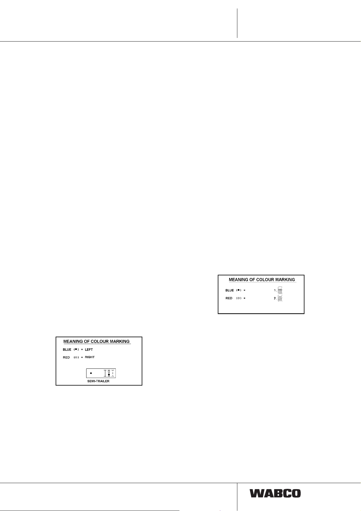
Colour Assignment
marking
yellow Back light right
RED
6 red Brake light right
4
8 green Turn signal left
3 brown Ground
BLUE
yellow Back light left
7 red Brake light left
30

Terminal X 41: ECAS Remote remote
control unit IRCU
TCE-Electronic
TCE-Elektronik
X 11 X 21 X 31
X12 X 22 X 32
X 13 X 23 X 33
X 14 X 24 X 34
X 41
X 42
X 43
X 44
X 51 X 61
X 52 X 62
X 53 X 63
X 54 X 64
449 635 ... 0
Cable overview
Used
Cable
449 635 050 0
L = 5 m
449 635 070 0
L = 7 m
TCE
see:
Drawing
449 635 000 0 one ECAS remote
Remark
remote control unit
IRCU
(Intelligent Remote
remote control unit)
446 056 202 0
4
Plug B
449 634 ... 0
Plug D
Plug A
Plug
A
Plug
B
Colour Assignment
13yellow Clock
21 red Supply
32brown Ground
54green Data 2
Used
Cable
449 634 232 0
L
= 5 m
1
L
= 5 m
2
449 634 239 0
L
= 18 m
1
L
= 5 m
2
see:
Remark
Drawing
449 634 000 0 two ECAS remote
remote control
units IRCU
(Intelligent Remote
remote control unit)
446 056 202 0
449 634 278 0
L
= 15 m
1
L
= 7 m
2
449 634 316 0
L
= 10 m
1
L
= 10 m
2
Plug B
Plug A
Plug
A
Plug
B
PlugDColour Assignment
13yellow Clock
21red Supply
32brown Ground
54green Data 2
13 yellow Clock
21 red Supply
32 brown Ground
64 green Data 1
31

4
449 654 ... 0
Plug D
TCE
Cable overview
Used
Cable
449 654 232 0
L
= 5 m
1
L
= 5 m
2
449 654 252 0
L
= 5 m
1
L
= 6 m
2
see:
Drawing
449 654 000 0 one ECAS remote
Remark
remote control unit
IRCU
and
one ECAS control
box
Plug B
449 655 ... 0
Plug A
Plug
A
13yellow Clock
21red Supply
32brown Ground
54green Data 2
13 yellow Clock
21 red Supply
32 brown Ground
64 green Data 1
26 Pin 15
Used
Cable
449 655 050 0
L = 5 m
Plug
B
PlugDColour Assignment
see:
Drawing
449 655 000 0 one ECAS control
Remark
box
32
Plug APlug B
Plug
A
13yellow Clock
21 red Supply
32brown Ground
54green Data 2
26 Pin 15
Plug
B
Colour Assignment

Terminal X42:
Height sensor and battery box
TCE-Elektronik
TCE-Electronic
X 11 X 21 X 31
X12 X 22 X 32
X 41
X 42
X 51 X 61
X 52 X 62
Cable overview
TCE
4
X 13 X 23 X 33
X 14 X 24 X 34
449 814 ... 0
Plug D
Plug B
X 43
X 44
X 53 X 63
X 54 X 64
Plug A
Used
Cable
449 814 228 0
L
= 3 m
1
L
= 5 m
2
449 814 272 0
L
= 5 m
1
L
= 7 m
2
449 814 292 0
L
= 5 m
1
L
= 9 m
2
Plug
A
see:
Remark
Drawing
449 814 000 0 one height sensor
441 050 012 0 and
battery box:
446 156 090 0
without 7.2 AH lead
gel battery.
446 156 094 0 with
batteries
Plug
PlugDColour Assignment
B
21 height sensor
32 Ground
61blue battery switch
72brown Ground
449 804 ... 0
Plug D
Plug B
Plug E
Plug A
Used
Cable
449 804 228 0
L
= 3 m
1
L
= 5 m
2
see:
Remark
Drawing
449 804 000 0 two height sensors
441 050 012 0 and
one battery box
446 156 090 0 without
7,2 AH lead gel
battery.
446 156 094 0 with
batteries
Plug
Assignment PlugAColourAssignme
B, D, E
D 1 Height
Sensor 2
2 Height
Sensor 2
D 2 Ground 3 Ground
B 1 Height
Sensor 1
4 Height
Sensor 1
B 2 Ground 3 Ground
E 1 Battery 6 blue Battery
E 2 Ground 7 brown Ground
nt
33

4
TCE
Terminal X 43:
Solenoid valve, 1-/2 point control
TCE-Elektronik
TCE-Electronic
X 11 X 21 X 31
X12 X 22 X 32
X 41
X 42
X 51 X 61
X 52 X 62
Cable overview
X 13 X 23 X 33
X 14 X 24 X 34
449 483 ... 0
X 43
X 44
X 53 X 63
X 54 X 64
Plug APlug B
Used
Cable
449 483 015 0
L = 1.5 m
449 483 025 0
L = 2.5 m
Plug
A
see:
Remark
Drawing
449 483 000 0 Solenoid valve,
472 900 053 0
472 900 055 0
472 880 030 0
Plug
Assignment
B
81 Pressurizing
44 Supply
72Rear axle right
33 Rear axle left
449 484 ... 0
Plug D
Plug B
Plug A
Used
Cable
449 484 085 0
L
= 1.5 m
1
L
= 1.5 m
2
449 484 127 0
L
= 2.5 m
1
L
= 2.5 m
2
see:
Remark
Drawing
449 484 000 0 Solenoid valve,
with
lifting axle control
472 905 114 0 with
transverse throttle
or
472 905 111 0
without transverse
throttle
Plug
A
Plug
B, D
Assignment
3D 1 Rear axle left
4D 4 Supply
7D 2Rear axle right
8D 3 Pressurizing
4B 4 Supply
5B 3lifting axle raise
6B 1Lifting axle lower
34

449 485 ... 0
Plug B
Cable overview
Used
Cable
449 485 106 0
L
= 1.5 m
1
L
= 1.5 m
2
Plug A
TCE
see:
Drawing
449 485 000 0 Solenoid valve,
Remark
Raising/Lowering
Valve
472 900 055 0
Spring returned
lifting axle valve
463 084 030 0
4
Plug C
449 494 ... 0
Plug D
Plug A
Plug
A
3B 3 Rear axle left
4
5C 1lifting axle raise
7B 2Rear axle right
8B 1 Pressurizing
Used
Cable
449 494 025 0
L
= 1.5 m
1
L
= 0.4 m
2
Plug
B, C
B 4 Supply
C 2 Supply
see:
Drawing
449 494 000 0 Solenoid valve,
Assignment
Remark
with 2 separate
lifting axles
472 905 114/111 0
and second lifting
axle solenoid valve
463 084 010 0
Plug E
Plug B
Plug
B, D, E
D 2 Lifting Axle 2 H 1 Lifting axle 2 raise
D 1 Supply
E 1 Rear axle left Supply
E 4 Supply Supply
E 2 Rear axle right 5 Lifting axle 1 raise
E 3 Pressurizing 6 Lifting axle 1 lower
B 4 Supply 3 Rear axle left
B 3 Lifting axle 1
B 1 Lifting axle 1
Assignment Plug
A
4
7 Rear axle right
raise
8 Pressurizing
lower
Assignment
Supply
35

4
TCE
Terminal X 44: Pressure sensor
TCE-Elektronik
TCE-Electronic
X 11 X 21 X 31 X 41 X 51 X 61
X12 X 22 X 32
X 42
X 52 X 62
Cable overview
X 13 X 23 X 33
X 14 X 24 X 34 X 44 X 54 X 64
449 823 ... 0
449 824 ... 0
X 43
X 53 X 63
Plug APlug B
Used
Cable
449 823 020 0
L
= 2 m
1
* with seal
Plug
A
53Pressure sensor
61 Supply
72 Ground
see:
Drawing
449 823 000 0 one pressure
Plug
B
Remark
sensor
441 040 007 0 (old)
441 040 015 0 (new)*
441 040 013 0 (new)
Assignment
Plug D
Plug B
Plug A
Used
Cable
449 824 108 0
L
= 3 m
1
L
= 2 m
2
* with seal
Plug
A
5B 3Pressure sensor 2
6B 1 Supply
7B 2 Ground
6D 1 Supply
7D 2 Ground
8D 3Pressure sensor 1
see:
Drawing
449 824 000 0 two
Plug
B, D
Remark
Pressure sensors
441 040 007 0 (old)
441 040 015 0 (new)*
441 040 013 0 (new)
Assignment
36

System functions
5.1 Brake lining wear indicator
-> Limit value indicator
Terminal X11
Advantages:
Retrofittable and not expensive
High degree of lining utilisation due to:
1. Skew wear compensation
2. Separate sensoring of both lining sides (no safety
allowance required for differential and disc wear)
3. On signal the residual thickness of lining is 2 mm.
TCE
Brake lining wear sensor
5
Schematic Z section through the brake
(PAN 19-1)
Installed brake lining wear sensor
Slide wire
Brake disc
Residual lining 2 mm
19 mm
Wear dimension
Report point
Cable abraded
Residual lining 2 mm
37

5
TCE
System functions
A maximum of up to six final value indicators (a wire
integrated in the brake lining) can be connected to TCE
for monitoring the state of wear of the disc brakes. The
driver is warned via the ABS warning light shortly before
and when the wear limit value is achieved.
When at a limit value indicator the wire is abraded in
braked mode, there will occur a short circuit to the
ground (ground connection between brake and frame
required) and warning level 1 is activated. At the first
warning level the ABS warning light flashes 4 times
(1 cycle) when the ignition is switched on.
WARNING SIGNAL SEQUENCE WARNING LEVEL 1
ON
OFF
Ignition
ON
When at a limit value indicator the wire is abraded for a
certain time, warning level 2 is activated. At the second
warning level the ABS warning light flashes 4 times 4
TIME
cycles (total of 16 flashes), when the ignition is switched
on.
WARNING SIGNAL SEQUENCE WARNING LEVEL 2
ON
OFF
Ignition
ON
The warning is interrupted when the vehicle's speed
exceeds 7 km/h. In case of system faults the ABS
warning light is activated continuously!
At the same time, the corresponding information is
transmitted via the motor vehicle/trailer interface and
can be shown on the display there.
The system automatically detects when new limit value
indicators are fitted after replacement of the brake lining.
All warning levels are deactivated after a time of 2
minutes (switch on the ignition for at least 2 minutes).
The warning light extinguishes not earlier than the next
ignition ON.
TIME
Wear indicators are available for following axles
Axle manufacturer SAF BPW
Brake type WABCO
PAN 19-1
PAN 19-1 plus
TDB-/
Test protocol No.
The TDB Test protocol No. can
be found on the reference plate
of the axle
Per axle
one set is required
Wear indicators are always packed
axlewise
TDB 0678
TDB 0749
12 999 755 VT 12 999 797 12 999 792 12 999 792
WABCO
PAN 22- 1
361-094-02
361-106-02
361-107-02
Knorr
SB 6-7
TDB 0605
TDB 0606
TDB 0590
TDB 0591
Knorr
SB 6-7
TDB 0568
TDB 0568
TDB 0632
38

System functions
I
N
N
TCE
5
5.2 Electrical supply
The table delivers an overview of the plug connections
acc. to their application, the second shows the contact
5.2.1 Standardized motor vehicle plug in
assignment.
connections
Terminals X12 and X13
Designation Standard Remark
ABS/EBS
Plug connection
ISO 7638 Supply and data communication
Trailer EBS, Running Gear Systems
1)
15 pin connection ISO 12098 Lighting, trailer supply, special functions
and data connection
1)
24 N ISO 1185 Alternatively to ISO 12098, lighting and
trailer supply
24 S ISO 3731 Alternatively to ISO 12098, lighting, special functions
and trailer supply
1)
Data connection acc. to ISO 11992
Figure: Standard motor vehicle-trailer - plug in connections
Terminal X12 Terminal X13
ISO 7638 (ABS 7-pin)
SO 7836 (ABS 7-polig)
Solenoid control valve +
Magnetregelventile +
Electronic supply +
Elektronikversorgung +
Electronic supply -
Elektronikversorgung -
Solenoid control valve -
Magnetregelventile -
Warning device
Warneinrichtung
CAN High 1)
CAN High 1)
CAN Low 1)
CAN Low 1)
1) Data connection acc. to ISO/DIS 11992
1) Datenverbindung nach ISO/DIS11992
Terminal X13
can be connected via an adapter 15 pin to 2 x 7 pin. However, then no
1
2
3
4
5
6
7
then CAN connection between motor vehicle and trailer as well as axle lifting and
traction help function.
ISO 1185 (24N)
Masse
Ground
Schlußlicht links
Rear light left
Fahrtrichtungs anzeiger links
Turn signal left
Br e ms l e u c h t e
Brake light
Fahrtrichtungs anzeiger rechts
Turn signal right
Schlußlicht rechts
Rear light right
Steuerung Anhängerbremsung
Control trailer brake valve
1
2
3
4
5
6
7
31/1
58L/2
L/3
54/4
R/5
58R/6
54g/7
ISO/DIS 12098 (15-polig)
Fahrtrichtungsanzeiger links
Turn signal left
Fahrtrichtungsanzeiger rechts
Turn signal right
ebelschlußleuchte
Fog rear light
M asse
Ground
Sch luß licht links
Rear light left
Sch luß licht rech ts
Rear light right
Bremsleuchte
Brake light
Rückfahrleuchte
Backing light
Stromversorgung (Kl. 30)
Power supply (pin 30)
Bremsbelagverschleißsensor
Brake lining wear sensor
Drucksensor Federspeicher
Pressure sensor spring b. actuator
Liftachsposition
Lifting axle position
M asse Datenleitungen
Ground data line
Datenleitung #1
Data line #1
Datenleitung #2
Data line #2
(15-pin)
ISO 3731 (24S)
Masse
Ground
nicht belegt
not connected
Rückfahr leucht e
Backing light
Stromversorgung (Kl. 30)
Power supply (pin 30)
Steuerung über Masse
Control via ground
Stromversorgung (Kl. 15)
Power supply (pin 15)
ebe ls chl ußl euc hte
Fog rear light
(1994)
1
2
3
4
5
6
7
8
9
10
11
12
13
14
15
(2001)
Steering axle lock
traction help
Axle lift
CAN High
CAN Low
1
2
3
4
5
6
7
31/1
58L/2
L/3
54/4
R/5
58R/6
54g/7
39

5
TCE
System functions
5.2.2 Supply
Three types of supply are supported:
• Standard supply ISO 7638 (X12) with Pin 30
(Pin 1), Pin 15 (Pin 2) for Braking and Running
Gear Systems, ISO 12098 (X13) with Pin 30
(Pin 9) for all other systems.
• Battery supply – Ramp operation:
only TCE level control function
• Battery supply - diagnostic mode:
only braking and RG systems
Central load dump protection for all TCE compo-
nents and connected external systems.
Table: TCE functional conditions
No. Designation Supply voltage Functional condition
Below range of service
1
voltage
Below
2
under voltage threshold
3 Service voltage range 18 V ≤ U
Over voltage threshold
4
exceeded
U
< 16 V Restricted functionality, if necessary, cut off
B
16 V ≤ U
U
> 32V Restricted functionality, if necessary, cut off
B
1)
< 18 V No control of levelling and lift axle valves, no
B
≤ 32 V All system functions active
B
Control of TCE battery supply as well as of con-
nected trailer systems (incl. diagnostic tool) for diagnostic and ramp operations (electronic levelling).
Moreover a connected tire pressure monitoring
(terminal X32) is permanently supplied via the trailer battery if a motor vehicle supply is missing.
Charging equipment with electronic protection for
trailer batteries up to 10Ah approx.
Sensoring of electrical motor vehicle supply lines.
Emergency supply of EBS via ISO 12098 brake
light and ground.
Dependent on the supply voltage the functional
conditions are complied acc. to the following table.
of certain switching parts
electrical supply of RGE systems
of certain switching parts.
1. Remark: The functional conditions of systems connected may be different.
5.2.2.1 Standard supply
The TCE is supplied via the plug connections acc. to
ISO 7638 (X12) Pin 30 (Pin 1) and Pin 15 (Pin 2). The
respective ground connections GND15 (Pin 3) and
GND30 (Pin 4) are monitored for breaks.
In case of a failure of ground lines GND15 or GND30 the
trailer warning light is activated.
TCE is switched on via
• cut in ISO 7638 Pin 15 (Pin 2)
• Data transfer from motor vehicle via ISO 7638 or
ISO 12098
• Operation of remote control unit (IRCU) for level
control
• Signal at special plug pins
• Connection of a diagnostic tool to connection X14.
Here activation of the TCE can follow via one or
several points at the same time.
The service voltage is measured and monitored for
falling below resp. exceeding the under resp.
overvoltage threshold. In case ISO 7638 (X12) Pin 15
(Pin 2) is cut in without ISO 7638 Pin 30 (Pin 1), this is
detected as failure and the trailer warning light
(ISO 7638, Pin 5) in the motor vehicle is activated.
5.2.2.2 Emergency supply of EBS
In case of a failure of supply ISO 7638, the TEBS is
additionally controlled via the brake light supply
ISO 12098. The TEBS is supplied only as long as the
brake is operated. This function is designed for
emergency cases only. At any rate the ISO 7638
connection has to be plugged.
40

System functions
TCE
5
5.3 Diagnostic mode and warning
light function; connection X14
If a communication is initialised from a connected test
device via the K line, EBS and all other modules with
connected consumers are switched on. To prevent an
overload, the supply mode ”battery supply - diagnostic
mode“ is communicated via the trailer data bus to the
modules and systems supplied. Functions which are not
actually to be checked shall be cut off from the systems
during this type of supply. This kind of operation is
automatically terminated if there is no communication
between test device and TCE or if the diagnostic mode
is explicitly closed by the test device.
5.3.1 Gateway ISO 7638 / ISO 12098
Trailer data bus
The TCE represents a bidirectional gateway between
data connection of ISO 7638 resp. ISO 12098 and the
CAN trailer data bus. Messages received will be filtered
complying with a programmed table and be transmitted
to the connected trailer systems / components. The
messages will be processed in dependence of event
and time. Messages from the motor vehicle which are to
be transmitted to the trailer data bus and messages from
the trailer bus which are to be transmitted to the motor
vehicle, will be processed event controlled. Messages to
be sent from TCE to the motor vehicle or on the trailer
data bus are processed simultaneously.
When messages on both data interfaces are received at
the same time the interface to the motor vehicle has
priority. Messages to send are respectively queued up
on both data connections according to their priorities.
responses, the TCE is responsible.
5.3.1.2 TCE Diagnosis
For parameter settings and system start-up incl.
calibrating a WABCO training is obligatory! For
registration and training schedule please phone to
+ 49 511 922 2971.
Diagnosis of TCE and systems connected is effected via
the diagnostic tool connection X14. The TCE diagnostic
functions correspond to the VDA recommendation and
the WABCO directive for KWP2000. They include the
following tasks:
– Parameter settings, system start-up
– Fault storage and access to fault storage
– System check / Service
Diagnosis is possible only by means of a PC. This
applies to end line tests at the vehicle manufacturer as
well as for troubleshooting in the workshop.
A diagnosis can be performed, when the TCE is
supplied via the 7 pin + 15 pin plug connection to the
trailer. Performance of the diagnosis is also possible
during the battery mode. However, in this battery mode
the connection to the diagnostic tool will be interrupted
5 minutes after the last query in order to save battery
power. A renewed diagnosis is enabled by connecting/
disconnecting the diagnostic plug to the vehicle.
During the diagnostic mode the vehicle can be raised
resp. lowered by means of the service unit. Only in the
calibrating mode this is impossible.
System requirement
– Remarkbook/Laptop or PC
5.3.1.1 Gateway diagnostic tool Trailer data
bus
The TCE represents a bidirectional gateway between
data connection of ISO 14230 resp. ISO 12098 and the
CAN trailer data bus. Messages received will be filtered
complying with a programmed table and be transmitted
to the connected trailer systems / components. The
messages are processed in dependence of events.
When messages on both data interfaces are received at
the same time, the interface to the motor vehicle has
priority. Messages to send are respectively queued up
on both data connections according to their priorities.
For maintaining the communication with the test device
resp. for keeping the timing especially in case of delayed
– Pentium processor
– 32 MB main memory, colour display 800x600
– approx. 10 MB free hard disc memory
3 ½" floppy disc drive
– COM interface (9-pin connection) for the
WABCO Diagnostic Interface
– Windows 95/98, Windows NT
Software order No.
446 301 680 0 German
In addition a diagnostic interface and a diagnostic
connector cable are required for the connection between
electronic and computer.
41

5
TCE
System functions
446 301 021 0 Diagnostic Interface Set (incl. a
diagnostic interface + diagnostic cable
to the PC)
446 300 329 2 trailer diagnostic cable, length 6 m
(Connecting cable between diagnostic
interface + external round diagnostic
plug terminal).
5.3.2 Warning Light Functions
A green system warning light can be connected to the
TCE. It indicates the following states:
Warning light status
– flashing: Display of general TCE errors
– on: trailer vehicle not within the
normal level
– off: vehicle within normal level
and without faults or ignition
switched off.
5.4 Freely programmable I/O
(Special modules) terminal X21
and X33
Implementation of vehicle and equipment specific
functions.
TCE II
At terminal X33 various ”special modules“, whose
parameters are to be set via the PC diagnosis, can be
released.
• Reading of analogue and digital information
• Control of electrical equipment
• Transfer and transmission of information via CAN
data connections
• Receiving and processing of CAN control data
After a reset all inputs / outputs are highly resistive. All
inputs / outputs are resistant to short circuits due to
supply voltage and ground.
Operating voltage monitoring
The operating voltage is measured and in case of being
above or below the operating voltage range, the change
to the respective mode will be effected.
Overload monitoring / cutting-off
In accordance with the directives to ECE-R 13 power
and operating voltage are monitored via plug connection
ISO 7638 and in case of an overload, electrical non
braking systems / consumers are cut off.
5.5 Trailer EBS and RGE
Connection Terminal X22
5.5.1 Trailer EBS
The Trailer EBS works independently from the TCE and
disposes of an own PC diagnostic tool which is operated
via the diagnostic connection. For more information
please see our brochure ”Trailer EBS - electronically
controlled brake system in trailer vehicles“,
Wabco print 815 010 019 3 and 815 010 020 3.
Important
TCE I:
In this connection the trailer modules 480 102 002/005 0
have to be used.
TCE II
Using TCE II the EBS axle modulator 480 102 015 0 (D)
should be connected. However, TCE II also works in
connection with previous modulators 480 102 002/005
0. In this case special requirements of the pressure
sensor connection have to be observed.
P
U
EBS modulator
480 102 002/005 0
P
U
P
U
P
U
Air bellows pressure
connection 5
EBS modulator
480 102 015 0
Air bellows pressure
connection 5
5.4.1 Monitoring functions
Watchdog (program running time monitoring )
Function of the micro controller resp. software
processing is monitored by an external watchdog.
Memory test
Parameter memory and ROM memory are cyclically
tested during operation.
42
EBS modulator
480 102 002/005 0
EBS modulator
480 102 015 0
If another EBS trailer modulator is used, this will be
reported as error on the TCE when the system is started.

System functions
TCE
5
Reason: The values of the pressure or axle load sensors
and of the brake lining wear sensors are already
supplied from the TCE electronic.
Remarks for the system start up
EBS modulator
• Modifications resp. differences between TCE I and
TCE II:
EBS-Modulator to be used for TCE I
480 102 002 0 (C)
480 102 005 0 (C+RSS)
EBS-Modulator to be used for TCE II
480 102 015 0 (D0).
• Voltage supply cable to be connected to TCE ECU.
• Create new set of parameters for modulator. Here
”electr. switch output 1+2“ has to be clicked as ”not
available“. The brake lining wear indicator as ”not
existing“.
EBS
• The sequence for system start up must be first EBS
and then TCE.
5.5.2 RGE Connection
When in the diagnostic mode the connection ”additional
function“ is activated, the trailer data bus and the voltage
supply are released.
The connection may be used for activation of a telematic
system or of a brake or chassis related system. The
electrical power is supplied via the TCE.
43

5
TCE
System functions
5.6 Rear underdrive protection terminals.
To terminals X23 and X24 the standard lighting is connected
Connecting plan 15 pin connector
7 Chamber light left
Pin No.:
31
54
Rfl
58L
Bli
Nsl
Function
Ground
Brake light
Backing light
Rear light
Flashing light
Rear fog light
Colour
white
red
purple
black
yellow
blue
1 Brake light right
2 Rear and identification light right
3 Rear fog light left
4 Rear and identification light right
5 Brake light left
6 Backing light right
7 Position lamp right
8 Position lamp left
9 Backing light left
10 Turn signal right
11 Rear fog light right
12 Ground
13 Turn signal left
14 Special Functions
15 Permanent plus
red
brown
blue
black
red
purple
white/black
white/blue
purple
green
blue
white
yellow
grey
orange
7 Chamber light right
Pin No.:
31
54
Rfl
58L
Bli
Nsl
Function
Ground
Brake light
Backing light
Rear light
Flashing light
Rear fog light
Colour
white
red
purple
black
yellow
blue
Rear light left
Position lamp left
Special Functions Permanent plus
e.g. from HELLA, status 03.2000
Only the standard lighting may be connected.
Connection of higher loads may cause cutting off the
TCE!
5.7 Ramp approach help
Terminal X31
TCE I:
The stopping distance is firmly adjusted to 40 cm.
TCE II
Here adjustability by means of setting a respective
parameter between 20 cm and 100 cm is enabled
(preadjusted reference value): 40 cm ).
The installation position of the ramp approach help
sensor can be adjusted between 0 and 100 cm.
This requires a functional test in order to prevent
”reflections“ of the supersonic sensor from the vehicle
Main supply
Rear light right
Position lamp right
chassis (backed position for sensor installation).
For certain purposes the ramp approach help can be cut
off for a short time. Cut off is done by operating the brake
after having shifted into the reverse gear. The positions
lamps are switched off after 30 sec. brake operation.
The ramp operation help remains in cut off mode during
the complete backing. By shifting into a forward gear
and renewed shifting into the reverse gear the system is
activated anew.
Reverse gear
Brake
Position
light
on
off
on
30 sec.
on
44

System functions
TCE
5
The ramp approach help supports the driver at backing
to loading ramps. Here in interaction with the WABCO
trailer EBS the trailer vehicle is automatically braked
before contacting the loading ramp in order to prevent
damages to vehicle and ramp. The braking pressure of
the WABCO trailer EBS is defined by the TCE
dependent on vehicle speed and the ultrasonic-wise
measured distance to the ramp.
Provided the speed is below 7 km/h the brake is
activated only for final stopping of the vehicle in front of
the ramp. In case the vehicle is > approaching the ramp
with 7 km/h, the ramp approach help induces short
brake impulses to remind the driver of the excess speed.
To avoid damages at loading and unloading due to
relative movements of the vehicle towards the ramp, a
distance between trailer and ramp is adhered.
Remark: This function is restricted to distance
recognition towards a loading ramp and does not
release the driver from his care to be directed during
backing.
Precondition for the function is a voltage supply of the
trailer via the 5 or 7 pin electrical plug connection to
ISO 7638 and a backing light signal (corresponding to a
shifted reverse gear) from the motor vehicle via the
15 pin plug connection to ISO 12098. Beyond that there
are no further requirements regarding the equipment of
the towing vehicle.
light on), provided the vehicle stands still with a
minimum distance (set parameter) from an obstacle.
When the vehicle has stopped in front of the ramp, the
brake is vented after ca. 3 seconds. By this the driver is
permitted to contact the ramp with the buffers, if
necessary. Provided the ramp is equipped with a
shelter, the semitrailer is first braked shelter oriented.
After 3 seconds the brake is released and the position
lamps are switched off. The ramp approach help
continues to be active, however, no automatic braking
will occur. The help function is activated for the second
time after having passed the shelter and a distance of
> 40 cm is measured. The position lamps will again
begin to flash. Monitoring of the speed limitations and of
all brake relevant parameters is done by the trailer EBS.
Reading of the backing light signal and specifying of the
brake pressure set point is done by the TCE.
Activation of the ramp approach help is communicated
to the driver via a flashing of the position lamps. In
relation to the distance towards the ramp the flashing
frequency is increased and changes to a permanent
light when the vehicle stands still.
Flashing frequencies:
slow flashing (1 Hz) > 3 m distant
slow flashing (2 Hz) 3 m - 1 m distant
rapid flashing (4 Hz) < 1 m distant
The ramp approach help is activated only at a vehicle
halt (v <= 2.5 km/h) by shifting the reverse gear (backing
In parallel to this an information will be transmitted to the
plug connection acc. to ISO 7638 via the CAN data
Detail ”rubber buffer“
Ram approach help sensor
Measure ”X“ until here!
Outer edge
Rubber buffer
from approx. 5 m distance
recognition of ramp
Underdrive protection
45

5
TCE
System functions
interference and can be displayed to the driver in the
motor vehicle. In case of position lamps being off, the
system is not active.
Via CAN line of ISO 12098 the distance to the obstacle
can be evaluated.
Radiation angle of ultrasonic sensors
Installation position of the ramp approach help
sensors
In the PC diagnosis is indicated under ”Structure and
lighting“, whether a ramp approach help is installed. For
this distance ”X“ between outer edge of ramp approach
help sensor (until WABCO logo) and farest vehicle edge
has to be indicated in cm.
5.8 Paver brake
TCE II is able to perform the function of a paver brake
without additional pneumatic valves. The corresponding
special module will be installed and the input brake
pressure can be adjusted between 0 and 2 bar.
At X13-8 resp. ISO 12098 PIN 10 +24 V are necessary
and at X33-13 the trigger contact of the modules is
connected (to ground). For activation the driver will
operate the activation switch in the cabin via ISO 12098
and start the dump action. As soon as the dump will lift,
the contact at X33-13 will be connected to ground and
TCE starts pressurising the brake pressure as set by
parameters.
This function can be activated only at standstill.
At v > 12.5 km/h the paver brake is deactivated and will
be reactivated only after stand still of the vehicle.
5.9 Electronic Levelling (ECAS) in
the TCE, Terminals X41, 42, 43
and X44
the known ECAS systems by means of the PC diagnosis
resp. the PC start-up.
TCE II
Due to new parameter settings the ECAS function
can be set out of service. A lift axle control is
nevertheless possible!
Function
The vehicle level is continuously recorded from the TCE
via max. 2 height sensors. In case of the occurrence of
deviations from the set reference level, TCE will activate
the respective solenoid valves. At this - each according
to the level - the airbellows will be pressurized or vented
until the nominal level will be achieved. Dynamic spring
movements will not be respected and do not cause a
response of the control.
Differences to the known ECAS
1. As a maximum 2 height sensors of TCE are
connectable. The TCE height sensor has the part
number 441 050 012 0.
Other height sensors are not permitted!
In TCE the electronic level control (ECAS) with one or
two height sensors as well as the electronic lift axle
control with automatic functions as traction help and
load dependant lowering are integrated. Setting of
parameters was significantly simplified in comparison to
46
Note:
All ECAS functions of our well known ECAS systems are
described in detail in our brochure ”Electronic levelling
control for air suspended trailer vehicles (ECAS),
functional and installation instructions“

System functions
TCE
5
This brochure can be ordered
under part No. 815 010 025 3 from WABCO.
5.9.1 Components
In the TCE the 4 terminals X41 to X44 are reserved for
ECAS components.
5.9.1.1 Control elements
at terminal X41 / X21
Part numbers
446 056 202 0 IRCU - Intelligent remote remote
control unit
446 156 000 0 Control box only for
TCE terminal X21
446 156 010 0 IRCU control box raising/lowering
446 156 011 0 IRCU control box raising/lowering
lifting axle function
446 156 012 0 IRCU control box raising/lowering
Drawbar vehicles
As maximum 2 control elements can be connected to
X41 and one control box to X21. TCE is activated by
pressing a button as far as terminal 30 is active or in in
the battery mode. By means of a further plug connection
between trailer and tractor the installation of a control
element in the motor vehicle is possible.
TCE I : A cable length of 25 m must not be exceeded.
TCE II : Cable lengths up to 60 m are permissible.
Control element 446 056 116 0 and 446 056 117 0 must
not be applied. They both do not cut off automatically,
thus a trailer battery - as far as terminal 30 (motor
vehicle) is active - resp. the motor vehicle battery will be
discharged. ”Stand-by“ mode is not possible
For loading and unloading the vehicle level can be
adapted to the loading ramp. The new reference level is
automatically kept constant during the following loading
and unloading phase.
Manual discharge of the lifting axle is always possible by
pressing the lifting axle button at empty or part loaded
vehicles, provided the admissible axle load is not
exceeded.
By using a switch or IRCU 2 further normal levels can be
adjusted.
The control element enables the user to change the
nominal level and the lifting axle position, to activate the
traction help and to preselect the desired vehicle level
(not with 446 156 xxx 0). The vehicle level can be
adjusted with the remote remote control unit only while
the vehicle is either stationary or moving at a speed
which is slower than a selected speed limit. This limit
speed is communicated to the ECU as part of the
procedure for setting the parameters.
IRCU Mode
Even with cut off ignition (IRCU mode) changes of the
nominal values and control operations can be
performed. For this the electronic being supplied from
pin 30/battery can be ”waked up“ (not possible with ...)
116 0 / ... 117 0).
The ”wake up“ is possible either by means of a remote
control unit or by means of a control box.
For the time being the endurance of the IRCU mode was
set to 15 seconds. This complies with the active time of
the TCE, waiting for user commands per remote control
unit or control box. Every time a button is pressed, the
interval is started anew.
Remote control unit / box
TCE II
If a control box is connected to X21, special parameter
settings are required for this. If a control box is
parameterized but not connected, TCE changes to
failure mode.
The control boxes 446 156 000 0
010 0
011 0
012 0
dispose of a warning light. In case of a failure of TCE the
warning light flashes resp. lights permanently when the
vehicle is outside the normal level. When this control box
is retrofitted in TCE I, the warning light comes on at
button operation. This is no indication for a failure.
Using a control element the nominal level of the vehicle
can be changed below a preset speed rate. Assembly of
several control elements to the chassis is possible.
Wake up of the TCE
By pressing one of the buttons „STOP“, „“ „“ or
normal level on the control box resp. by pressing any
button of the remote control unit the system can be
”waked“.
When one of the above mentioned buttons is operated
for at least 100 ms, the system is ”waked“ and the ECAS
warning lamp is switched on - as far as installed. First
the self test is running (present duration 5 seconds).
Only after termination of that test the buttons are
accepted and the ECAS solenoid valves are operated.
A raised lifting axle resp. a released trailing axle will be
lowered or loaded automatically.
Deceleration time in IRCU mode
During the IRCU mode the level is adjusted after
expiration of the ”Control delay during standstill“.
Changes of nominal level are started without delay.
47

5
TCE
System functions
Tolerances in IRCU mode
The ”normal“ tolerances as existing at switched on
ignition are effective.
Termination of IRCU mode
All adjustments will be breaked and the stand-by
operation will be terminated, if one of the following
conditions is fulfilled:
– Start of stand-by mode by pressing the STOP
button of IRCU for at least 2 seconds
– Switch on of ignition
– Duration (15 seconds) expired.
5.9.1.2 Remote remote control unit
Remote control unit 446 056 202 0 is installed on the
vehicle preferably inside a box. Contact with the ECU is
established via a spiral cable and a terminal on the
vehicle frame.
Various remote control units are available depending on
the type of system used. The following picture shows the
remote control unit 446 056 202 0. The functions of this
RCU are:
– Lowering and lifting of the superstructure via all
axles simultaneously, via front or rear axle resp.
axle assembly separately and with the
corresponding system design separated to right
and left side.
– Raising and lowering of the lifting axle and thereby
switching off or on any fully automatic lifting axle
operation, respectively reducing or increasing the
load on the trailing axle.
– Activating the traction help function
– Preselection of a normal level from up to 3 possible
normal levels and adjustment of the actual - means
preselected - normal level
– Storing of up to 2 preference (i.e. memory) levels
and setting these levels when the appropriate
button is pressed briefly.
– Adjustment of the vehicle to STAND-BY operation
– Instantaneous interruption of any raising or
lowering processes by pressing the STOP button.
The remote control unit can perform only functions,
which are available on this unit and whose parameters
are set in the TCE. That means for instance that on a
vehicle without lifting axle the button for lifting axle
function is not applicable.
The layout of the remote remote control unit shows three
lamps (referred to as check lamps) in its upper row
which inform the user which axle has been preselected
for the adjustment to be made.
Below these are the 3 preselect buttons in a row. Each
of these buttons is located below the corresponding
check lamp. If one of these buttons is pressed, the
corresponding check lamp will come on, indicating to the
user that the preselected axle can be actuated.
Preselection button front axle
or left vehicle side at
existing right/left control
Memory level 2 – button
M 2
Memory level 1 – button
M 1
RAISE button
LOWER button
48
Indication lamp front axle
Indication lamp rear axle
Indication lamp lifting axle
Preselect button rear axle
or right vehicle side
at existing
existing right/left control
Preselect button lifting axle
normal level button
Stop button

System functions
TCE
5
A renewed operation of the preselection button causes
also the belonging check lamp to go out. It now makes
evident to the user that the input mode of the remote
remote control unit is interrupted. Any activation by
using the remote control unit is not possible. For any
changes of the reference level for the whole of the
vehicle, the preselect buttons for front and rear axles
must be pressed. There upon both corresponding check
lamps must be on to indicate that the system is ready for
actuation.
IMPORTANT! Usually any input using the remote
control unit begins by preselecting the desired
axle(s) and ends by cancelling the input mode.
raising and lowering of the chassis
By pressing the ”RAISE“ or ”LOWER“ buttons, the ECU
is given a changed reference level for the superstructure
above the preselected axles. Now without any delay the
superstructure changes its distance to the axle as long
as the respective button is pressed. Releasing the
button terminates the change of the nominal value, the
latest nominal value at releasing the button is regarded
as new nominal value.
Raising and lowering the lifting axle
Briefly pressing the ”RAISE“ or ”LOWER“ buttons after
preselecting the lifting axle causes the lifting axle to be
raised or lowered and the weight resting on the trailing
axle increased or decreased. Raising, i.e. increasing the
weight, is only possible provided the defined permitted
maximum pressure in the main axle's supporting
bellows is not exceeded. Lowering the lifting axle resp.
increasing the weight on the trailing axle causes cut off
of a lifting / trailing axle automatic with possibly set
parameters.
Switching automatic lifting axle operation on
and off
As described above, automatic operation of the lifting/
trailing axle can be switched off by pressing the
”LOWER“ button provided at least one lifting/trailing axle
had been automatically raised/relieved due to a light
load. Switching off automatic lifting axle operation
means that the lifting axle which before was raised
automatically now is lowered, or the load on any relieved
trailing axle will be increased.
Automatic operation is switched on again by means of:
- Remote control unit
(Preselection lifting axle, button ”lifting“).
In case of a semi automatic lifting axle with set
parameters the lifting axle is lowering in
dependence on the pressure. Raising of the
lifting axle is enabled by remote control unit or
switch.
- Switch on and off ignition
Traction help
By means of button ”M1“ and preselected lifting axle the
traction help is activated ( only when parameters are set
for lifting and trailing axle automatic!). Traction help is
terminated by pressing the STOP button or by exceeding the parameterized speed. Observe specifications
of axle manufacturers.
A traction help cannot be started with the remote control
unit.
Manoeuvring aid
By pressing button ”M1“ and preselected lifting axle the
traction help is activated ( only when parameters are set
for lifting and trailing axle automatic!). The manoeuvring
aid is interrupted by pressing the STOP button or when
v > 10 km/h. A manoeuvring aid cannot be started with
the remote control unit.
Normal level
If respective parameters are set the normal levels I, II
and III can be adjusted via the remote control unit (only
with RCU 446 056 202 0). When a remote control unit
is connected, no 3rd normal level must be
parameterized per remote control unit. In order to
adjust another normal level the remote control unit must
be activated. For that press the button for axle selection.
Subsequently another normal level can be selected via
a button combination. This level is active as long as a
new normal level will be selected per remote control unit.
By pressing the FN button the new selected normal level
will be set in future again and again. With the following
button combinations you may select the active normal
level:
Press the green normal level button and at the same
time
– button ”M1“ for normal level I
– button ”M2“ for normal level II
– the button ” “ for normal level III
To avoid undesired normal level activations,
parameters should not be set for various normal
levels.
Memory Levels
(only with remote control unit 446 056 202 0)
If a certain vehicle level is to be set frequently when the
vehicle is being loaded or unloaded, that level can be
stored and set again as often as required at the press of
a button.
By pressing the ”STOP“ button and then also pressing
either the ”M1“ or ”M2“ memory button, an existing
reference level can be stored as the preferential (or
memory) level.
The stored values aren't lost when the ignition is
switched off. They apply to the whole of the vehicle, i.e.
49

5
TCE
System functions
when retrieving it, it is sufficient to simply preselect one
axle. By then briefly pressing the corresponding memory
button, i.e. ”M1“ or ”M2“, the vehicle's superstructure is
immediately brought to the stored level.
The remote control unit does not have any memory
levels.
Stop
By pressing the ”STOP“ button, all level control
processes are stopped immediately, the present level
being recognised as the reference level. This function
primarily permits the operator to cancel any automatic
changes in the vehicle's level (memory, normal level) if
he considers that the continuation of that control process
would be hazardous.
If the STOP button is held down and the ignition
switched off, the vehicle is put into STAND-BY mode.
Speed dependency
Functions ”Raising and lowering of superstructure“ and
”Memory level“ are available only at standstill as well as
below a selectable speed rate. Control functions started
below this speed are brought to completion even if the
speed is exceeded whilst they are in progress.
Manual lifting / trailing axle control via RCU is accepted
by the electronic only below a further speed rate to be
preselected.
Pressing several buttons simultaneously
If several buttons are pressed simultaneously and these
do not represent a plausible combination, no command
will be accepted when a specific level change is started,
and the STOP function is performed instead.
Simultaneous operation of both control units
If both control units are operated simultaneously, the
stop function will be activated. Further targeted height
changes are possible after that only when meanwhile no
further buttons are operated.
Disconnecting the remote control unit
If during the raising / lowering action the control unit will
be disconnected, the stop function is performed.
Priority
If an unloading level function has been activated and a
raise/lower command is given via the remote control
unit, the command from the remote control unit will be
executed.
The remote control unit has a high priority within the
system. So, if the control function has failed, the
vehicle's superstructure can be taken to a reasonable
level by using the ”Raise“ and ”Lower“ functions to allow
the vehicle to be driven to the workshop.
5.9.1.3 ECAS - Control unit for semitrailers
with lifting axle: 446 156 000 0 for X21
Stand-By Mode
The stand-by mode is a service mode which keeps the
normal level constant with switched off ignition for a
preselected period (max. 63 hours).
Stand-by can be activated the following way:
When the ignition is switched off with operated stop
button, a stand-by mode is activated for a preselected
time.
When TCE is supplied only via pin 30 or via a battery,
the stand-by mode can be activated by operating the
stop button for more than 2 seconds.
A raised lifting axle resp. a released trailing axle will be
lowered or loaded automatically.
The deceleration time in the stand-by mode is set by
means of a parameter in the PC diagnosis. As well the
tolerances during the stand-by mode. Thus the air
consumption with frequent significant load changes (due
to driving with a fork lift) is minimized
Stand-by mode is terminated by switching on the
ignition, two times operation of a RCU button, if the
stand-by time is over, or at the occurrence of a failure.
The control box 446 156 0xx 0 can be assembled
directly on the vehicle frame. Assembly position
must be in such a distance from the lifting axle that
the user must not be injured at a lifting axle
operation.
50

System functions
TCE
5
In addition to the known control box also IRCU boxes
are available whose functions are equal to that of the
control box.
446 156 010 0 IRCU control box Raise / Lower
446 156 011 0 IRCU control box raising/lowering
Lifting axle function
446 156 012 0 IRCU control box raising/lowering
Drawbar vehicle
Functions of control unit and control box:
Raising/Lowering X X
Raising/lowering of
lifting axle
Traction help X –
Manoeuvring aid X –
normal level II, III X –
Memory Level X –
Stop X X
Stand-by X X
Wake up at
Ignition off
Normal level X X
X(X)
XX
sensors are connectable, at which only height sensor
012 0 is allowed to be connected.
Sensor lever
Sensor shaft
Lever guide
Height sensor with a lever
fastened to the height sensor shaft
The height sensor 441 050 012 0 continuously picks up
any changes in the height of the superstructure. It is
designed for installation on the vehicle frame.
The measuring principle of the height sensor is inductive
which means the position (distance) of an anchor inside
a coil is measured. An externally initiated rotary motion
via a lever is transformed inside the sensor into a linear
movement of the anchor into the coil without clearance,
following the crankshaft drive principle. The 'dipping
movement' of the ferro-magnetic armature into the
stationary coil causes a phase displacement between
current and voltage. The ECU measures the
displacement of the current and converts it into counts.
TCE II:
The warning lamp of control box 446 156 000 0 is
activated: Failures detected by the TCE are
indicated by flashing of the warning lamp. In case
the present vehicle level is outside the normal level
(FN), this is indicated by a permanent light of the
WL. In case a control box is assembled, it should be
abandoned from the 3rd drinving level per control
element in order to avoid maloperations.
5.9.2 Height sensor(s) and trailer
battery at terminal X42
5.9.2.1 Height sensor
Part numbers:
441 050 012 0 Height Sensor
446 156 090 0 Battery box without battery
446 156 094 0 Battery box with batteries
In ECAS systems always at least one height sensor
has to be installed. For TCE a maximum of two height
The height sensor cannot be functionally tested by using
a voltage meter. If a check of the height sensor is
necessary, the coil resistance of the height sensor can
be checked. The resistance must be approx. 120 ohm.
The coil's induction is evaluated more than 50 times a
second by a special evaluation circuit within the ECU.
The ECU monitors the proper function.
The height sensor is located on the vehicle's frame near
the axle whose air suspension bellows are to be
controlled. The master gauge for the holes used for
fastening the sensor is identical to that of a conventional
air suspension valve.
Steered (front) axles usually have one height sensor
(1-point control) above the centre of the axle. (Leading)
axles with a steady contact to the ground, can have one
or even two height sensors fitted; if the latter is the case,
they should be as far apart as possible in order to
achieve the best possible control performance for the
individual height sensors (2-point control on one axle).
51

5
TCE
System functions
The height sensor is firmly attached to the axle to be
controlled via a threaded rod which has rubber end
pieces acting as dampers and compensating devices.
Installation possibilities:
torque acting on the sensor shaft. For this reason, all
swiveling axes must be in parallel to each other.
Only one type of height sensor is available. The sensor
level can, however, be mounted in steps of 90 degrees
on the sensor shaft which can be smoothly turned in the
sensor housing. For accurate operation and measurement of values, the sensor shaft has to be properly
aligned. To facilitate this, two projections have been provided on the sensor shaft which are used as lever
guides. It is important that the height sensor moves freely across the whole of its operating range, and that the
lever can only move in the way intended.
When mounting the height sensor onto the vehicle's
superstructure, the sensor's raising and lowering
reactions must be taken into account. Dipping of the
cylinder in direction RAISE increases the induction,
extending in direction LOWER reduces it. The values
measured can be displayed on suitable diagnostic
equipment (e.g. Diagnostic Controller, PC).
Raising the superstructure increases and lowering
the superstructure reduces the displayed measured
values.
* = 2 Coding projections of height sensor lever guide
Important for installation
The height sensor has a measuring range from + 43° to
- 40° starting from a horizontal sensor lever position. The
sectional view of the height sensor, looking onto the
sensor lever attachment, displays the arrangement of
the positive and negative areas. Ideally the whole of the
excursion range is used, with the lever being close to
horizontal at the normal level. The maximum excursion
of the lever (+/-50°) may not be exceeded. For the lever
linkage, a threaded rod is preferable to a smooth rod,
because this way slipping within the rubber is virtually
impossible.
The length of the sensor lever is selectable but must be
identical for the height sensors on one axle. A short
sensor lever ensures a high resolution of the measured
values even when the change in height is slight;
however, it can only cover a short range of adjustment.
A long sensor lever achieves the opposite: a long
suspension travel can be covered at the expense of the
resolution of measured values. It should always be
targeted to make use of an angular range as large as
possible.
Bending the lever at right angles must be avoided
because this might result in an impermissible tilting
In the normal level the height sensor lever must have a
rectangular (90°) position to the height sensor. This can
be aligned by means of a 4 mm pin.
5.9.2.2 Battery supply
TCE enables the connection of a trailer battery. With
connected termial 15 this is charged via the TCE
(charging current via ISO 7638 terminal 30 (Pin 1)).
The TCE integrated charging control fulfills the following
boundary conditions:
• Direct battery charging via operating voltage with up
to 6A.
• 100% charging via voltage increase with 1 A max.
• Control of charging voltage (voltage increase)
dependent on charging state.
• Battery capacity 2 Ah ... 10 Ah.
• Protection against total discharge
Battery supply via connected systems is activated only
when there is no supply via pin connection acc. to
ISO 7638 terminal 30 (Pin 1). When for instance a trailer
is disconnected, TCE remains to be active. The positive
line of the battery has to be fused at the battery (10 A).
Charging characteristic for the assembled battery must
be preset in the PC diagnosis.
52

System functions
TCE
5
Per control unit / box the height levelling can be set to
stand-by mode so that in case of height changes the
system automatically will adjust. However, the control
characteristic depends on the parameters set.
Additionally the superstructure can be raised resp.
lowered by means of the control unit / box.
Battery charge
The trailer battery is charged by TCE only with switched
on ignition (terminal 15, ISO 7638). Moreover the
charging connection is activated only when a connected
battery was detected. Criterion for this is the idle running
voltage at the time of switching in of 14V at the battery
connection at present.
For monitoring of the battery charging the battery
voltage, the voltage at pin 30 (ISO 7638), the charging
current and the charging capacity are calculated.
Besides charging current and capacity there is defined
for lead gel accumulators a voltage of 29 V at pin 30 as
interrupting criterion for the charging procedure. In
addition the charging is cyclically interrupted to prevent
the battery from damages. Charging time and and
interrupting cycle depend on the battery type.
For the purposes of controlling the system, the ECAS
solenoid valve is the interface between the electronic
output signals from the electronic control unit and the
pneumatic actuating signals for the air suspension
bellows. Each one ECAS solenoid valve is installed per
axle resp. axle assembly.
In the ECAS solenoid valve several individual solenoid
valves are combined in a block. Each of these solenoid
valves is a combination of an individual solenoid with
one or two pneumatic valves with one or two control
slides.
The electrical control signal for activation of the
individual solenoids is sent from the electronic control
unit by means of the electrical plugs on the individual
solenoids or individual solenoid valve blocks. This
individual solenoid effects opening/closing of the
respective valves resp. moving of the respective slides.
This control represents an indirect control since the
valve solenoids are opening a valve seat. Via this
opened valve seat the supply pressure or air supply
flows to the control pistons resp. control slide and
pressurizes it so that it moves into the position desired.
5.9.2.3 Solenoid valves at terminal X43
Part number Description
472 905 114 0 ECAS valve for 1 point,
R/L, Lifting Axle with traction
help
472 905 111 0 ECAS valve for 2 point,
R/L, Lifting Axle with traction
help
old: 472 900 055 0
new: 472 880 030 0
old: 472 900 053 0
new: 472 880 001 0
old: 472 900 058 0
new: 472 880 021 0
463 084 010 0 ECAS valve for Lifting Axle
463 084 030 0 ECAS valve for Lifting Axle
Trailers with 1 point, 2 point or lateral control (right/left).
Drawbar trailers (front/rear).
Lift axle valve(s) for one or two separately controlled lift
axle(s).
ECAS valve for
R/L at rear axle
ECAS valve for 2 point,
R/L at front or rear axle
ECAS valve for 1 point,
R/L at front axle
2 circuit) without traction help
(1 circuit) without traction help
Starting from the solenoid control of the pneumatic
valves, 2 types of valves are distinguished:
The spring returned valve acts as a 3/2 or 2/2
directional control valve in the ECAS solenoid valve.
It is mainly used to control the supporting bellows at
the front axle or the rear axle with permanent ground
contact. The valve can be designed as slide or seat
valve.
The spring returned valve acts as a 3/3 ode 2/2
directional control valve in the ECAS solenoid valve.
It is mainly used for controlling the lifting axle bellow
in combination with the supporting bellows of the
lifting axle.
By means of impulse controlled valves a lifting axle
automatic can be realised. Usually the solenoid valve
block for control of the lifting bellow is flanged to the
solenoid valve block for control of the main axle.
Due to the individual solenoid valves no partial load
pressures at the valve seats are possible. The three
functions:
• Pressure build-up
• Pressure maintenance
• Pressure reduction
53

5
TCE
System functions
are obtained by combining the individual solenoid valve
functions. Changed balance conditions of the air
suspension system are only monitored by the height
sensor, interpreted by the electronic and the required
commands be transmitted to the ECAS solenoid valve.
The ECAS solenoid valve is located on the frame –
preferably on a frame cross-member – above the axle to
be controlled, or above the axle assembly to be
controlled. The pipes and cables leading off to the
bellows should be symmetrical, i.e. identical in length
and diameter. Take care that the proper allocation of
electrical and air connections follows the numbering
system.
There are three main different groups of ECAS solenoid
valves, depending on their location:
• Front axle valve (also: Front Axle valve)
• Rear axle valve (also: Rear Axle valve)
• Rear axle/lifting axle valve (also: Rear Axle/
Lifting Axle valve)
The Front Axle valve is located near the front axle and
controls the supporting bellows for the front axle. Usually
the Front Axle valve is only equipped with a 2/2 way
valve for the front axle (steering axle) - 1 point controlled
axle. The process of increasing and decreasing the
pressure is taken over by the 3/2-way valve of the rear
axle valve.
The Rear Axle valve is the core of an ECAS system with
no automatic lifting axle facilities. It is located near the
rear axle and controls the supporting bellows of the rear
axle. An additional air exit can be used to pressurize or
vent any downstream consumers, e.g. a Front Axle
valve on drawbar trailers.
with one 2/2-way valve – on a 1-point controlled axle –
or two 2/2-way valves – on a 2-point controlled axle.
There are three
3/3-way valves in the block of lifting axle valves. These
are actuated by two valve solenoids and are responsible
for controlling the lifting bellows and the supporting
bellows of the first lifting axle.
Due to that the pinning of the electrical pins is not
uniform, clear assignments can be done only by means
of a circuit diagram (see annex), the following directive
is applicable for the pneumatic pinning:
Connection 1 Supply from the reservoir for
downstream consumers (only with Rear
Axle/Lifting Axle valves).
Connection 11 Supply from the reservoir for
downstream consumers (only with
Front Axle valves and Rear Axle
valves).
Connection 12 Control pressure from the reservoir for
controlling the control elements in the
ECAS solenoid valve (only with Front
Axle valves and Rear Axle valves).
Connection 13 Not relevant.
Connection 14 Supply connection coming from Rear
Axle valve (only with Front Axle valves).
Connection 21 with dedicated Rear Axle valves: Output
for connection 14 of Front Axle valve.
Only on Rear Axle/Lifting Axle valves:
Output for (left-hand) supporting
bellows of the axle(s) which is (are) on
the ground.
The Rear Axle valve is usually equipped with a 3/2-way
valve for the pressurising/venting function and,
depending on the control version of the ECAS system,
with one 2/2-way valve – on a 1-point controlled axle –
or two 2/2-way valves – on a 2-point controlled axle.
The Rear Axle/Lifting Axle valve is the core valve of a
system with automatic lifting axle control. This valve
consists of a rear axle block whose function corresponds
to that of the rear axle valve, and a lift axle block.
It is located near the rear axle and controls not only the
supporting bellows of the rear axle but also the lifting
bellows and the supporting bellows of the first lifting
axle. An additional air exit can be used to pressurize or
vent any downstream consumers, e.g. a Front Axle
valve on drawbar trailers.
The Rear Axle valve is usually equipped with a 3/2-way
valve for the pressurising/venting function and,
depending on the control version of the ECAS system,
54
Connection 22 Output for (right-hand) supporting
bellows of the axles(s) which is (are) on
the ground.
connection 23 On dedicated Front Axle or Rear Axle
valves: Output for (left-hand) supporting
bellows of the axle(s) which is (are) on
the ground.
Only on Rear Axle/Lifting Axle valves:
Output for (left-hand) supporting
bellows of the lifting axle for fully
automatic lifting axle operation.
Connection 24 Output for (right-hand) supporting
bellows of the lifting axle for fully
automatic lifting axle operation.
Connection 25 Output to the lifting bellows of the lifting
axle.
Connection 26 Only on Rear Axle/Lifting Axle valves:
Possible output for connection 14 of
Front Axle valve.

System functions
TCE
5
On buses also output for supporting
bellows on the front axle for the
'kneeling' function.
Connection 27 no relevant in trailers, in buses also
outlet to supporting bellows of front axle
at kneeling.
Connection 3 Exhaust to downstream consumers
(only with Rear Axle valves).
Connection 31 Exhaust to downstream consumers in
the rear axle block (only with Rear Axle/
Lifting Axle valves).
Connection 32 Exhaust to downstream consumers in
the lifting axle block (only with Rear
Axle/Lifting Axle valves).
At present, ECAS solenoid valves with DIN bayonet
connectors are used. The solenoids are no longer
visible, they are located inside a block of solenoid
valves.
ECAS solenoid valve for implementing a
2-point control on the driven axle
472 900 053 0 or
472 880 001 0 (new)
Rear Axle valve with DIN bayonet
472 900 055 0 or
472 880 030 0 (new)
ECAS solenoid valve for front axle
472 900 058 0 or
472 880 021 0 (new)
55

5
TCE
System functions
Pulse-controlled sliding valve
(Rear axle and lifting axle control)
472 905 114 0
Connection
for Rear Axle
Connection
for Lifting Axle
Pressure sensor
For utilising pressure-controlled ECAS functions, a
pressure sensor must be used. This pressure sensor
picks up the pressure in the supporting bellows on the
axle which is always in contact with the ground (on the
trailer this is usually a rear axle) for controlling the lifting
axle, the traction help or for compensating the tire
deflection.
The pressure is recorded by means of extension
measuring strips. As the pressure is increased, the
resistance at a Wheatstone bridge changes, thus
effecting a voltage in proportion to the pressure.
Depending on the type of pressure sensor used, it is
energised with 8 ... 32 V. Via a signaling line (sensor
cable) the voltage generated by the pressure is
transmitted to the ECU.
In a pressureless condition (pressure sensor offset), the
output is 0.5 volts. The transmissible voltage at the
upper limit of the measuring valve at a pressure of 10 bar
is 4.5 V. The max. admissible pressure of 16 bar for
pressure sensors must not be exceeded.
The output of measuring values is done in digital form,
i.e. in steps. The values measured can be displayed on
a suitable PC diagnostic equipment.
5.9.2.4 Pressure sensor(s) at
terminal X44
Part numbers:
441 040 007 0 Pressure sensor expires 2001
441 040 013 0 Pressure sensor new
441 040 015 0 Pressure sensor new
(with sealing ring)
In case no EBS D modulator is installed, it is possible to
connect one or two pressure sensors for axle load
calculation, at which one pressure sensor is required for
the load sensing EBS control. The EBS D modulator has
an integrated pressure sensor and is evaluated by the
TCE II. In this case the parameter ”pressure sensor in
the EBS“ has to be selected.
The pressure sensor is connected to a separate terminal
on the supporting bellows or on a T-piece on the bellows'
inlet port. At any rate the pressure sensor must not be
installed in the air line between supporting bellow and
ECAS solenoid valve and also not directly onto the
bellow plate, because errors due to the high dynamic at
actual pressurizing and venting operations may occur.
Pressure Sensor 441 040 007 0 ... 013 0 /... ... 015 0
with DIN bayonet connection for the sensor cable.
Connection:
(Design with DIN bayonet)
Positive line
+
Ground line -
Signaling line
56

System functions
TCE
5
5.9.2.5 Axle load calculation
In TCE II the axle load calculation can be separately set
for each axle (by parameters). This requires a calibration
of the respective axle load characteristic via the TCE
diagnostic program. By means of the recorded data the
TCE II software calculates the effective characteristic for
the respective axle and calculates the axle loads by
means of the connected sensor(s).
Service schedule
The TCE II disposes of a socalled service schedule: By
means of date, covered distance and/or service hours a
service interval can be defined. Via the PC diagnosis or
the telematic function this information can be displayed.
5.10 Pneumatic Components and
Installation Instructions
Like conventional air suspension systems, electronic air
suspension systems include pneumatic components
such as: air reservoirs, charging valves, plastic pipes
and couplings. As in any air suspension system, the
circuit for ancillary consumers is secured against the
service brake circuit with a charging valve without return
flow of 6.0 bar (e.g. 434 100 125 0). The size of the air
reservoirs for the air suspension system depends on the
number of axles and the system requirements: For
vehicles without lifting axles a volume of 60-80 l is
sufficient, only for systems with lifting axles reservoir
sizes of 80-120 l should be preferred. This provides
sufficient reserves for the control process in loading
ramp operation and for frequent lifting axle operation
without requesting any additional compressed air from
the motor vehicle. In this respect, ECAS is not different
from other air suspension systems.
Regarding plastic pipes, ECAS achieves considerable
savings compared to other systems which offer the
same scope of function. On a vehicle with lifting axle
control and an air-suspension valve with height limiting,
this will be more than 30 meters. Because of the valve's
large nominal width, the nominal width of the plastic
pipes between the solenoid valve and the bellows is
between 10 and 12 mm. 12 mm is recommended unless
the axle manufacturer or WABCO's diagrams require
otherwise. The supply line's nominal width should never
be less than 12 mm. In order to prevent tire damages
due to a too fast raising and lowering, the pipe nominal
width of 8 mm towards the lifting bellow should be
accepted as recommendation.
To protect the lifting bellows against excessive
pressures, and against crinkling, WABCO has provided
the use of pressure limiting valves and charging valves
in the diagram as option. The instructions of the lifting
bellows' manufacturers are binding.
Most of the vehicle manufacturers apply plug-in
connections, available from WABCO under the brand
Anoflex. ECAS also achieves savings regarding screwin connections. No such screw-in work is required at the
rotary slide valve or the air-suspension valve for the
remote control unit or the height sensor. Even the
expenditures for vehicle owners are reduced
significantly when they use ECAS. Surveys among
vehicle manufacturers fitting ECAS in series production
have shown that installation times were reduced in
comparison to conventional systems.
In case of service test connections are essential for
quickly locating any defects. In the extreme case of a
total system failure nevertheless the vehicle should
remain to be able to be raised or lowered in laden or
unladen state. Therefore at least 2 test connections for
service brake and supporting bellow should lead to the
atmosphere at a 1-point control. This allows the driver to
externally lower the vehicle (pressing the test
connection), or to raise it. (Connecting the two ports by
means of the test hose and pressurizing via the service
brake system.) After deconnection the pressure is
included in the air suspensions, since an ECAS system
without power supply interrupts all connections. Only a
normal leakage will then cause the superstructure to be
lowered again over time. While checking the normal
level, usually the vehicle can be driven across a short
distance to the nearest workshop for repair.
When selecting suitable sites for the individual
components, there are no definite rules other than those
defined for the fitting position (see Annex - outline
drawings). However, accessibility for servicing is
important. In detail:
Remote Control Unit:
Its location varies with the type of system used, and the
type of vehicle. In any case an externally well accessible
connection with cap should be installed at a water
protected location. For tank and chemical vehicles often
the lateral cases are used for that purpose.
Solenoid valve:
For sure the easy accessibility in case of necessary
service is the most important criterion, because in case
of service the incoming pneumatic lines have to be
disassembled here. The lifting axle block consists of two
valve units screwed together. The part containing the
pneumatic ports is the 'front'. Thus the 'rear' would be
the valve portion facing the frame. The plastic pipes
57

5
TCE
System functions
leading to the supporting bellows should be of equal
length.
The pressure sensor
It is located near the supporting bellow and is
recommended for connection to a test valve
(463 710 998 0) for pressure simulation. This allows all
of the vehicle's control processes to be simulated and
checked, regardless of the load it carries, e.g. to check
the behaviour of its lifting axle. For that it should be
mounted within reach and accessible without too great
efforts. Any pressure peaks are suppressed by the ECU.
does not make contact in the upper or lower area. It
should be taken into consideration that during the driving
operation additional jounce travels often will occur and
therefore sufficient distance to the limit stops is required.
If possible chose a site which is protected against falling
rocks and splash water. For systems with two height
sensors at the rear axle install these as far from each
other as possible. In order to prevent transverse forces
all swiveling axles must have the same direction. The
lever also should not be bent at right angles. As linking
of the lever to the axle a threaded rod should be
preferred. Unintentional slipping thus is nearly excluded.
The lever has three holes for length adjustment. The
longer the lever, the greater the possible control range.
At the calibrated or main normal level, a lever position of
90° to the sensor is recommended to achieve the best
possible solution. This can be simply realised by moving
the lever on the threaded rod during the normal level and
subsequent tightening.
Pressure sensor with test connection
The height sensor
Instead of the conventional levelling valve the height
sensor is installed. The master gauge for installation is
fully identical and the installation site as well. It is
important that for the whole of the control range the lever
58

System start-up and Diagnosis
Height sensor at the Rear Axle
TCE
6
The electrical supply lines:
Excess lengths of sensor and solenoid lines should be
arranged in Z form as already known from ABS. Cables
which have to be routed along permanently vibrating
objects should be attached using double cable binders
894 326 012 4. Such rocking or vibration will eventually
result in strain-hardening and consequently premature
breaks. All cable binders should only be tightened to that
extent that the cables are sufficiently held in place. This
prevents premature breaks of the cable cords and thus
of the electrical conductor.
6.1 System start-up and Diagnosis
6.1.1 Calibrating
As part of the start-up procedure for a new vehicle, the
sensors have to be calibrated after the parameters have
been set. The height sensors integrated in the system
have to be ”introduced“ to the electronic. This means
that a reference value for the electronic control unit has
to be defined. The calibration process has to be
repeated every time the electronic control unit is to work
with a new sensor. This also applies for:
• Exchange of a sensor
• Exchange of the electronic control unit
By means of the PIN (i.e. Personal Identification
Number) the calibration can be performed as often as
required. This enables the driver to change the normal
level(s). Calibration of a drawbar trailer with two height
sensors means simultaneous calibration of Front Axle
and Rear Axle height sensors.
6.1.1.1 Height sensor calibration
The process of calibrating the height sensor means that
the height sensor is adjusted to the electronic control
unit. As a rule, the vehicle's superstructure is moved to
normal level I, to the upper and lower levels (stops
beyond which no movement is possible when raising
and lowering) and the respective level is informed to the
electronic control unit.
Correct calibration requires the following preparatory
work to be carried out diligently:
– Place the vehicle on a surface which is horizontal
and even.
– Make sure that the height sensor has been
properly installed and that its lever can move freely
across the whole of the raising/lowering range.
– If the vehicle has two height sensors on one axle,
the bellows on both sides are connected to each
other by means of a test hose (balancing the
pressure to spread the load evenly across the
axle).
59

6
TCE
System start-up and Diagnosis
– Don't brake the vehicle (protect it against rolling
movements)
– Make sure sufficient air supply
– Driving height in mm as distance between
superstructure and vehicle axle respectively
according to one of the present reference
dimensions.
Upper edge
Chassis
OKR
Lower edge
UKR
Chassis
CDE
A
F
B
Survey on the various reference dimensions for
height sensor calibration
A Lower edge (frame) longitudinal beam until middle
of the axle
B Lower edge longitudinal beam until upper side of
the axle
– measuring as close as possible to the air bellow
(seen in axle direction).
The calculated calibration heights should be recorded,
to have the values available in case of a service
required.
Apply only one measuring procedure for a vehicle with
several axles. Indication of the heights is made in the
following sequence driving height, maximum level,
minimum level.
Example for a complete designation:
Reference type A, V 250/390/202, RL 273/420/210,
RR 275/422/213 (R= R
If the electronic control unit is to be replaced and the
calibration data for the vehicle are not known, the
calibration data for the height sensors of the former
electronic control unit may be displayed in the menu
”system, calibration data, height sensors“. If this is no
longer possible, the following assumptions may be used:
At normal normal level I the height sensor lever will
be aligned horizontally.
Movement to the upper and lower levels takes
place until the superstructure can no longer be
raised or lowered.
ear Left, dimensions in mm).
C Upper side longitudinal beam until middle of the
axle
C Upper side longitudinal beam until upper side of
the axle
E Upperside longitudinal beam until road surface
E Upperside longitudinal beam until road surface
For a uniform documentation standard measuring points
are defined according to the shown survey of reference
dimensions. If possible indicate the calibrating heights in
accordance with the specifications of the axle
manufacturer. As a rule this means the distance
between the axle centre and the lower edge of the
longitudinal beam. Dimension A in the drawing. The
indication of the measured heights always must
also show the respective letter in order to identify
them correctly.
Avoid to make use of reference dimensions E and F,
since with this measurement also the tire deflection is
respected and thus results may be wrong depending on
the vehicle load. For calculation of the calibration height
the following principles are to be kept:
– measuring directly at the axle, not in front of or after
the wheel (seen in travelling direction),
6.1.1.2 Height sensor calibration with the PC
To calibrate 3 calibration levels, move to each level to be
calibrated in the following sequence: normal level I,
upper level and lower level. Do this using the DC/PC.
Note: When calibrating, an increase of the normal
level with raised lifting axle and tire deflection
compensation has to be taken into account.
a) First the vehicle is taken to the established normal
level I (for the front axle and the rear axle
respectively). Then the calibration process is
initiated (actual levels are now stored as normal
levels).
b) Move the vehicle to the level of the upper stop. Re-
initiate the calibration process. (Actual levels are
stored as upper stop levels.) To protect the stops,
the electronic control unit will automatically reduce
the value for the upper stop level by 3 counts.
c) Move the vehicle to the level of the lower stop. Re-
initiate the calibration process. (Actual levels are
stored as lower stop levels.)
60

System start-up and Diagnosis
TCE
6
Note: When using the Diagnostic Controller for
calibration, the vehicle's levels cannot be changed using
the remote control unit.
After the individual calibration phases are completed,
the Diagnostic Controller will check the fault memory
and display whether calibration has been achieved
successfully or not.
For a successful completion of the calibration the
following principles for the height sensor values HSV
have to be considered:
– The entered height sensor values must be greater
than 4 counts and less than 255 counts.
4 counts < HSV < 255 counts
– The upper stop level UL must be larger than the
total of normal level NL increased by 3 counts and
three times the reference value tolerance.
– The lower stop level LL must be smaller than the
normal level NL reduced by the double reference
value tolerance DHSL.
A second possibility is the calibration of a driving level
and manual entry of the upper and lower stop level. This
kind of calibration can be reasonable when the
superstructure is intended to move to the stops. Thus
stop release in the upper level can be avoided.
Also for this procedure the calibration guidelines have to
be observed. Starting from the normal level rear left and
rear right, the calibration values for the ”upper/lower stop
level rear“ can be defined as follows:
1. Calculate the differences between the ”upper stop
level rear left“ – ”normal level rear left“ and ”upper
stop level rear right“ – ”normal level rear right“.
2. Add the smaller difference to the expected
calibration value ”normal level rear left“ to obtain the
calibration value to be entered for the ”upper stop
level rear“.
3. Calculate the differences between the ”normal level
rear left“ – ”lower stop level rear left“ and ”normal
level rear right“ – ”lower stop level rear right“.
4. Subtract the smaller difference from the expected
calibration value ”normal level rear left“ to obtain the
calibration value to be entered for the ”lower stop
level rear“.
During the calibration procedure the calculated values
will be entered into the PC.
After the individual calibration phases are completed,
the Diagnostic Controller will check the fault memory
and display whether calibration has been achieved
successfully or not.
The third possibility to communicate calibration values to
the electronic is direct input of the height sensor values.
This can be accomplished only with a PIN. To do this,
the height sensor values have to be known. The direct
input is done with the PC diagnostic program under
system/calibration data height sensors.
If values are entered for these parameters, it may be that
calibration will not lead to the desired result. When
calibrating a partially laden vehicle, the lifting axle must
be lowered. If at a partially laden vehicle the lifting axle
is raised during calibrating, an undesired increase of the
normal level will result. The vehicle then perhaps might
be in unladen condition with raised lifting axle above the
admissible vehicle height.
As well for a partially laden resp. fully laden vehicle the
compensation of the tire deflection must be considered.
That means the vehicle must be calibrated partially or
fully laden deducting the tire deflection compensation!
61

7
When starting the diagnosis the following
interfaces will appear. The individual
parameters are explained as follows:
TCE
PC Diagnosis
7.1 Start and diagnostic menu
After start of the diagnostic program the data as stored
in the TCE will appear. On the right side the basic
configuration of the trailer vehicles is shown.
In the TCE diagnosis version 2.01 (de) the start screen
was extended by the following information:
– Date / time (GMT). This will appear after
adjustment. GMT stands for ”Greenwich time“.
(Germany is located 1 hour before this time zone)
– Display of voltage Pin 15
– Display of voltage Pin 30 of the 7 pin trailer plug
– Display of voltage Pin 30 of the 15 pin trailer plug
– Display of voltage of trailer battery, as far as
installed
– Display of a possibly existing voltage potential
between ground connections of supply plug
ISO 12098 (15 pin) and ISO 7638 (7 pin). As a rule
(standard design) the display should be within the
62
scope < 2 V. In case of a respective failure entry
this value has to be considered.
Information to part number, production date, serial
number, software version, diagnostic recognition,
mileage counter, operating hours counter and battery
hours counter is shown. Vehicle manufacturer and
chassis number will be shown only after system start-up,
as far as they were entered.
Mileage counter, this displays the covered miles of the
trailer vehicle with connected TCE. May be different
from EBS mileage counter!
Operating hours counter, displays the period, over
which TCE was supplied via Pin 30.
Battery hours counter, displays the period, over which
TCE was supplied only via the battery.
Actual or stored information will be displayed red
resp. blue.

PC Diagnosis
TCE
7
7.2 Vehicle definition
Input must be from top to bottom resp. on the next
screens from top left to bottom right. If this procedure is
not kept, errors of the system may occur.
On the vehicle definition screen and the following
screens the basic configuration is adjusted.
So first of all the vehicle type has to be selected.
Axles & sensors:
Here the number of front and rear axles is to be set.
Axle assignment:
In the first line indicate on which axle(s) the first lifting
axle valve is acting and under the designation
F = spring return and I = impulse control the mechanical
structure of the valve.
In the second line select a second lifting axle valve. This
valve is always designed as spring returned.
In the third line must indicate whether brake lining wear
sensors are installed and if yes on which axle. If one axle
is selected, the field 'wear sensor' becomes active.
With a for the traction help the first axle can be
released in accordance with legal directives.
With a for the manoeuvring aid the last axle can be
released.
The additional valve should be selected in order to
ensure a comfortable control of the traction resp.
manoeuvring aid at spring returned lifting axle valves.
This is effected by means of ”pressure keep“. This is
active only in combination with the first lifting axle valve.
Wear indicators
When wear sensors are installed, identification of the
sensor type is required.
Levelling control:
As a maximum two height sensors can be installed on
the vehicle.
For semitrailers must be decided whether two height
sensors for lateral control are to be installed or if one or
two height sensors on the rear axle are to be assembled.
For drawbar trailers always one height sensor is
obligatory at front and rear axle.
TCE II
For vehicles without ECAS function select ”no level
control“. Connection of height sensors and ECAS valve
block can be omitted then. A lift axle control is
nevertheless possible!
Pressure sensors:
Two pressure sensors can be mounted as maximum.
The pressure sensor always has to record the bellow
pressure of that axle controlled by the trailer modulator.
2
63

7
TCE
PC Diagnosis
TCE II
In vehicles with TEBS-D the modulator has an
integrated pressure sensor. In this case no pressure
sensor has to be connected to the TCE II. Select option
”... there of one pressure sensor in the EBS“.
7.2.1 Superstructure & lighting
Lighting:
In case of activating 'standard', will be displayed for
the lamps to be connected. Connect terminal X23 at
standard. If luggage superstructure is selected, connect
terminal X23 and X33. For tank superstructure connect
X23, X33 and X34.
If a lamp is not connected, select ”freely defined“ and
of the respective lamp has to be removed.
A new option is that the backing light right and/or left is
additionally selectable as well as also the rear fog light
right/left.
Now also the connection of LED lamps to TCE II is
possible! Moreover the light failure recognition was
improved. Via parameter settings by PC the ”sensibility“
for ”cable break recognition“ can be set.
Standard monitoring:
In the case of a failure of one of two connected lights
(e.g. brake light), this will not be detected as an error.
Extended monitoring:
At this adjustment the failure of the light with same or
higher electrical power is detected.
LED monitoring:
With light emitting diodes nobreak recognition.
Ramp approach help / paver brake:
In case of installing a ramp approach help, the
installation position (see page 44) has to be indicated.
The stopping distance can be varied from 100 cm to
20 cm. For paver brake mode the brake pressure can be
adjusted from 0 to 2 bar.
Trailer battery:
In this case selection of the correct accumulator is
important. Acid accumulators resp. lead gel
accumulators have different charging characteristics.
Green system warning light:
The green system warning light shows messages from
the system with flashing light. In case the vehicle is
outside the normal level, the system warning light is
permanently flashing.
64

PC Diagnosis
TCE
7
Connection of a CAN electronic
As a maximum three further CAN electronics can be
installed on the vehicle.
If 'additional functions' is selected, it is necessary to
activate a CAN electronic at terminal X22 via a second
CAN line.
Tire pressure monitoring must be selected in case an
IVTM electronic is connected at X32.
In order to enable control of CAN superstructure
systems, a CAN electronic may be connected at
terminal X32.
Additional lines of the 15 pin trailer socket:
Not available: Selection via special module interface
possible.
7.2.2 Special modules
The menu item special modules was added in the new
TCE diagnostic program 2.01.
Here the modules are listed which are integrated in the
respective TCE and available as parameters.
A description of the module is under menu item: Info
module X to be seen.
The special modules shown on the left side can be
selected. The selected modules will then be shown on
the right side. Some special modules as for instance the
ISS (integrated speed switch) have parameters, which
can be shown on the right side, too. With respect to fully
functionable special modules further parameters have to
be set in the diagnostic software, e.g. the level switch
will be functionable only then when also the ECAS
parameter ”Normal level via switch“ was adjusted.
Manoeuvring aid:
The manoeuvring aid supports improved and tire saving
back driving in the manoeuvring mode. This can be
activated by means of a control unit or a press button to
Ubat from the motor vehicle. A special module must be
parameterized for that. It is deactivated when exceeding
a rate of 10km/h or ignition ”OFF“ resp. pressing the
STOP button or pressing the button for more than
5 seconds. An excess pressure of the admitted bellow
pressure by the 1,5-fold value will cause deactivation.
This does not affect the level and is not adapted. An
offset is not possible! For vehicles without lifting axle at
the respective axle, the bellow pressure for raising must
be set lower in the special parameter than the empty
bellow pressure. Only then the axle is running
permanently pressurized.
65

7
TCE
PC Diagnosis
7.2.3 ECAS Parameter
Here now the last standard parameter page for TCE. If
no special parameters are required, the parameter
settings can be terminated after this surface pate.
Normal level selection:
Preselect whether the 2nd or 3rd normal level are to be
activated via control units or a switch.
TCE I: Normal level not to be activated via switch
TCE II: Entire functional range
Normal level 2
When the second normal level is chosen via switch/
control unit, indicate the difference in height to the
normal level in +/- counts, after the function was
selected. Whether the second normal level is activated
by means of a switch or a control unit depends on the
choice under 'level selection'.
When the 2nd normal level shall be speed controlled,
indicate additionally to the difference in height in+/counts also the speed rates for the first and second
normal level.
3. level:
Selection is possible whether the third level shall be an
unloading level, thus active only at standstill, or a driving
level. In both cases the difference in height to the
calibrated normal level has to be indicated in +/- counts.
Speed threshold between standstill and drive is that
driving speed at which the normal level is automatically
adjusted. In case a control box is used, it should be
abandoned from the 3rd driving level via control unit to
avoid maloperations.
New:
Selection of the control box is not relevant in this
parameter display because a respective choice has to
be made in the new diagnostic program under ”special
modules“.
Vehicle selection:
The difference between fast unloading and standard
vehicle is the shorter subsequent control time at
unloading of the vehicle. Selection of fast unloading
means reaction of the vehicle to changes in load within
one second. As a rule the vehicle reacts within six
seconds.
Air bellows pressure:
The pressure at maximum admitted axle load is required
to calculate the values for lifting axle raise and lower, the
traction help pressure and the tire deflection
compensation. This value is a must.
66

PC Diagnosis
TCE
7
Lifting Axle Control
Choosing the full automatic function of the lifting axle,
the lifting axle will automatically be lowered or loaden
after having exceeded the set pressure value for the
supporting bellow. Raising of the lifting axle/loading of
the trailing axle follows automatically as well after falling
below the set pressure value for the supporting bellow.
Choosing the semi automatic function of the lifting axle
results only in an automatic lowering of the lifting axle.
Raising of the lifting axle is done manually via a control
element or switch, e.g. in the cabin.
Traction help:
The traction help has to be adjusted in accordance
to legal directives resp. specification of the axle
manufacturer.
Possible preadjustments are as follows:
The maximum axle load for the axles remaining on the
ground is increased by 30 % for all 3 types of traction
help.
As already described the traction help can be started via
control unit or by means of a press button against Ubat+
from the motor vehicle. Therefore a special module has
to be parameterized. The traction help effects more
traction onto the driven axle in the starting gears and can
be effectively used in narrow bends. The traction help is
cut off when exceeding a rate of 30km/h, pressing the
STOP button, ignition OFF or pressing the button for
more than 5 seconds! In the traction help mode the
normal level is kept - an offset is not possible! For
vehicles without lifting axle at the respective axle, the
bellow pressure for raising must be set lower in the
special parameter than the empty bellow pressure. Only
then the axle is running permanently pressurized.
Traction help to EG
The traction help to ”EG“ is active up to 30 km/h with
30 % overload. It is possible to activate this until a speed
rate of 25 km/h. Both values are able to be reduced by
means of the diagnosis. Increase is not possible.
Traction help to 'time limit'
Traction help to ”time limit“ is active for 90 seconds with
max. 30 % overload. After a compulsory break of
50 seconds the traction help can be started a fresh,
provided 20 km/h are not exceeded. In case 30 km/h is
exceeded, the traction help will cut off automatically.
Traction help to 'Northland'
Traction help to ”Northland“ can be cut in until a speed
rate of 25 km/h and remains active until cut off
irrespective of the speed.
Vehicle data:
Here indication of manufacturer and chassis number is
necessary, When these data are missing they also will
not appear in the various protocols resp. on the first
diagnostic interface.
The following pages have to be respected
only if special parameter settings are
required.
7.3 Special parameters
Tire Deflection Compensation:
This is permanently active. At the maximum value of the
air bellow pressure 10 counts will be compensated. In
the case of vehicles with larger transport volumes there
are selected besides small wheels also short spring
travels in order to maintain the legally specified vehicle
heights. Due to this the superstructure might easily hit
the rubber buffers when the vehicle is laden.
With increasing loads the distance axle/superstructure
is extended and thus with constant vehicle height a
longer spring travel is realised.
Control delay:
Control delay while stationary delivers a period, in
which the reference value control is made while
stationary.
Control delay while driving delivers the period, in
which the reference value control is made while driving.
Vehicles with swing axles (Inloaders) require an
adjustment different from the standard parameter set!
Control delay in Stand-By delivers the period, in which
the height sensor signals at stationary vehicles in Standby mode have to be continuously beyond the admissible
nominal value tolerance range to effect a subsequent
adjustment.
Admissible level deviations:
Admissible right/left deviation of the levels at the
rear axle, required only for systems with 2 height
sensors at the rear axle. It defines the permissible slant
of the superstructure if the load is not evenly distributed.
In the case of independent wheel suspensions this value
should be cut off.
Max. right/left deviation during raising/lowering in
the levels at the rear axle refers only to axles with 2
height sensors. This value indicates the admissible
range during larger level changes (raising/lowering). At
unilaterally loaded vehicles, the less loaded side will
quicker be raised resp. lowered than the other. This may
67

7
TCE
PC Diagnosis
possibly cause a dangerous slant as the level is being
changed. By pulsing the bellows supporting the lighter
load, a more even raising/lowering process is achieved.
At vehicles with swing axles (inloaders) the adjusted
value must not exceed 5!
Max. front/rear deviation at raising/lowering into the
levels refers to full-air cushioned vehicles. In the case of
level changes the front and the rear of superstructure
should reach the new reference level simultaneously.
The axle with the shorter distance will be raised/lowered
respectively slower. A minor permissible deviations
causes constant pulsing of the solenoid valves during
the control process and should, therefore, be avoided.
Admissible level increase 7 sec. after start off resp.
at activated mode 'unloading level' refers to
unloading actions. This option permits an exceeding of
the reference level of the superstructure distance above
the axle. When 7 seconds after start off or with activated
unloading level an exceeding of the reference level plus
the count values of this option is measured at all
distance sensors, the ECU detects an unloading action.
An immediate adjustment to the level nominal level plus
the selected count value is the consequence.
as long as the vehicle has not exceeded a speed of
k.p.h. since start off. At vehicle speeds of more than
10 km/h this control is not effective and will be
reactivated only at the start of driving after a renewed
stand still.
Speeds:
Speed rate up to which targeted level changes by
means of the control unit/box can be effected
describes the limit speed at which the control unit/box
keeps the buttons active during driving. This function is
designed for installation of a control unit in the motor
vehicle. This allows memory levels, raising, lowering,
etc. to be carried out. After exceeding of the adjusted
speed the control unit will be cut off. A level deviation
from the normal level is controlled as long as achieving
the driving speed at which the normal level is
automatically adjusted.
Driving speed at which the normal level is
automatically adjusted. When exceeding the set
speed rate the actual level will be automatically
adjusted. The actual normal level is depending on the
position of the driving level switch resp. the normal level
preselection via control unit or on the adjustment of the
speed dependent normal level control.
If the function unloading level is active, an immediate
control even at brake actuations will occur, when the
level change exceeds the value nominal level plus
selected count value. The control process will continue
68
This parameter is of major importance for the attaching
or detaching of semitrailers. Here a speed should be
selected being high enough to prevent an automatic
activation of the driving level at slow speeds.

PC Diagnosis
TCE
7
Tolerances:
The values describe the admitted values above or below
the nominal level. Tolerance range is two times the
indicated value.
Plausibility:
The values for the limit of the plausibility check at
lowering of the respective axles define the limit value of
the distance sensor. Below this the electronic does not
detect a plausibility message during lowering of the
superstructure. Depending on the definition of the lowest
permissible level, the function of the parameter varies:
In case the rubber buffer shall be the lower height limit?
Then enter a ”-“ value. The value to be entered is defined
by the elasticity of the rubber buffers, because an empty
vehicle does not compress the buffer as much as a
laden vehicle. If the calibration was done on the laden
vehicle, the unladen vehicle will not reach this lowest
level even when the bellows are completely exhausted.
This results in a plausibility message.
Recommendation: if calibration is done in an unladen
state, enter a value between -10 and -25. In order to
avoid a plausibility message, when only one side is
resting on the buffer due to the vehicle being in a tilting
position.
Shall the lower height limit be above the rubber buffer?
Then enter a ”+“ value. The exhausting process is
terminated, when the sum of the lower level + this
parameter has fallen below the specified value and no
further change in height will occur during the indicated
period of the plausibility check. Since usually plausibility
messages are only possible in tilting positions of the
vehicle or on an uneven ground, an adjustment between
5 and 20 is recommended.
The parameter plausibility check defines a period in
which the electronic control unit expects a command to
be executed or continued. If a given command is not
followed by any reaction, the ECU detects implausible
behaviour. A useful adjustment is a period of
30 seconds.
Calibration levels:
As a standard here ”three calibration levels“ are to be
selected. ECU is expecting during the calibration
process the moving towards three levels, normal level,
upper and lower level.
When ”calibrate only normal level“ is selected, the upper
and lower level must be known as count values and be
entered as number values during the calibration
process. The nominal level is moved to during the
calibration process.
69

7
TCE
PC Diagnosis
Lifting Axle Control:
Here different lift axle functions can be selected.
Lower lift axle is adjusted as a standard to ”Lift axle to
be lowered at ignition off“. The lifting axle(s) will be
lowered only if contact at Terminal 30 is maintained for
a short time after the ignition has been switched off. Not
after detaching the ABS coiled cable.
Raise lift axle is adjusted as standard to ”Lift axle to be
raised only at speed“. With ignition on the lift axle
remains at the ground and will be raised only after the
preset driving speed is achieved beyond which the lift
axle is raised in case of a fully automatic function. This
adjustment has a positive effect on construction vehicles
and on motor vehicles with a poor cold start ability. The
decision on whether the lifting axle(s) can be raised is
made while the vehicle is stationary.
When the lift axle shall be raised at ignition on, the first
line has to be chosen. Raising of the lift axle will then
follow in dependence on the load.
Driving speed above which the lift axle is raised at a
fully automatic function delivers the speed at which
the lift axle is raised after ignition on. This parameter is
only active at corresponding selection of lift axle to be
raised. Recommended here is an adjustment of 10 ...
20 km/h. Around 20 km/h the tire circumference speed
is sufficient to remove adherent impurities.
Lower lift axle, here the pressure of the air bellows can
be manually changed. As a standard the value is ajusted
from the max. permitted value of the axle load minus
10 %.
Raise lift axle, here the pressure of the air bellows can
be manually changed. As a standard this value will be
calculated dependent on the max. permitted axle load
value and the number of axles and lift axles.
Same is true for the next two parameters.
Increase of normal level with raised lift axle will
deliver the value for the increase. Thus an improved
clearance for the wheels of the lifting axle is resulting.
The value set for this parameter is important for the
calibration process. This is exclusively active to increase
the driving level depending on the option increase of
driving level with an unladen or partially laden vehicle.
The increase of the driving level is not active during the
traction help mode.
Driving speed until which a manual lift axle control
is possible, delivers the value until which a control is
possible. Lowering the lifting axle at higher speeds could
possibly cause tire damages due to higher forces
becoming effective while the tires make contact with the
road surface.
Special parameter 3:
Changed structure, identical content!
In case of vehicles with two separately controlled lift
axles, this value should be smaller than the driving
speed up to which a manual lift axle control is possible.
This would also effect raising of the 2nd lifting axle,
when driving after an effective traction, and not only after
standstill of the vehicle. Also after unloading, the lifting
axle will not be raised earlier then when set value has
been exceeded.
Increases of normal levels (with raised lift axle), can
refer to the first and second normal level or to the lowest
level only. As a standard it is referred to the lowest
normal level. In case the first line is selected, the third
level should be the highest of the three possible levels.
The level will be raised only if the vehicle is actually at its
driving level.
Automatic lowering is effective to all lift axles as a
standard. When the input automatic lowering shall be
exclusively effective to the 2nd lift axle, select the
second line.
Old designation: Overload protection
New: Static overload protection, i.e.., dynamic peaks
are ”admissible“ resp. will be filtered out.
Traction help:
The traction help will be adjusted in accordance with the
selected type of traction help and the respective
admitted legislation.
The traction help has to be adjusted in accordance
to legal directives resp. specification of the axle
manufacturer.
Differences in air bellow pressures:
At vehicles with a height sensor the level will be directly
moved to.
At vehicles with two height sensors ”minimizing of bellow
pressure differences“ is activated. Prior to addressing
the driving level, the vehicle's superstructure is lowered
slightly and then raised to its driving level by
simultaneously pressurizing the bellows. This ensures a
balance in pressures on the left-hand side and the righthand side of the bellows.
70

PC Diagnosis
TCE
7
Buffer recognition:
The buffer recognition time defines the period, in which
the ECU is to recognize the lower stop (”rubber buffer“).
When at sending the command 'lower superstructure' no
more height change takes place during this period and
the distance of the superstructure above the axle is on
one level, the pulsing of the ECAS solenoid valve will be
interrupted.
Axle load calculation:
TCE I:
Cannot be activated.
TCE II:
Function to calculate the axle load can be activated. It
requires to perform the ”axle load calibration“ at the
system start-up of the TCE II.
Period:
Stand-by time may be entered here in steps of
15 minutes.
Follow-up time with unloading level switched on
delivers a follow-up time after ignition off. If the
superstructure is at the upper stop while switching off
the ignition, ECAS will lower the superstructure to the
upper stop level with voltage from terminal 30. This
means venting the bellows so that the shock absorber
stop will no longer be stressed.
This function is valuable when a vehicle is just suddenly
and very quickly unloaded. Since ECAS needs a certain
time for readjusting to the selected unloading level, the
bellows pressurized with value ”laden“ press the
superstructure against the belts. In the case of the
absence of belts, the vibration dampers may be
extended to their maximum. An extraordinary tensile
load is the result. Consequence would be that ECAS
would have to vent the supporting bellows such as to
readjust the unlading level. If the ignition is switched off
at that point, ECAS would interrupt the control process.
Due to the lack of any power supply, the superstructure
would remain in its upper position for some time, and the
strain on the buffers, or stops, could be excessive.
The same exessive strain could occur if the ignition of a
tanker truck using ECAS is switched off while it is being
unloaded by means of an external pump. Also in this
case with an adjusted unloading level avoidance of an
overstress of the stops by means of this parameter is
possible.
Overload protection:
Admissible overload pressure, reports the admissible
pressure of the supporting bellow which must not be
exceeded. If this value is exceeded, further pressurizing
is impossible and the superstructure is lowered to the
buffers.
When this happens, return to normal operating
conditions is possible after having reduced the axle load
and switching on/off the ignition.
71

7
TCE
PC Diagnosis
7.4 Axle load calibration:
If under ”special parameter 3“ determination
of the axle load was selected a calibration of
the axles is required. For calibrating the axle
load the vehicle has to be set to the normal
level.
Only thus relevant pressures and
consequently the weight of the load can be
determined.
For each axle the empty and partial weight
has to be indicated in kg and bar, as well as
the admissible axle load. By means of the
pressure sensor TCE calculates the
individual axle loads as well as the total load.
This is transferred to the motor vehicle via
the CAN data connection of the 7 pin plug
connection to ISO 7638.
The axle load determination is only as exact
as was calibrated. An unexact entry of the
empty resp. partial load may result in
immense deviations. The most precise
method to calibrate a vehicle type is to load
the vehicle respectively and to enter
pressure and weight in tons.
7.5 Switch Positions /
Outputs
In menu ”Measured values / switch positions“ the set parameters for the switches
can be tested. If for instance in the parameters the special module 2 is selected, the
TCE port at X13 Pin 9 is indicated and a
functional test detects whether the signal is
recognized from the correct switch input.
TCE outlets can be likewise tested under
menu ”Measured values / outlets“.
72

7.6 Service management
It is possible to adjust service intervals in the
TCE for the most different activities. These
can depend on a date, mileage or service
hours. If 90% of a service interval are
achieved, a message on the first page of the
diagnostic software will appear. Under
”service management“ the required acitivity
can be read out and be confirmed after
successful service completion.
Dependence on the date can be shown only
when date and time are prior adjusted in the
TCE. This is shown on the first page of the
diagnostic software.
PC Diagnosis
TCE
7
7.7 System label
HERSTELLER
MANUFACTURER
CONSTRUCTEUR
WABCO TEILENUMMER
WABCO PART NUMBER
RÉFERENCE WABCO
SERIENNUMMER
SERIAL NUMBER
NUMERO DE SÉRIE
FAHRZEUG-IDENT.NR.
CHASSIS NUMBER
NUMERO DE CHASSIS
PARAMETERSATZ-NUMMER
PARAMETER SETTING NO.
NO. DE LA LISTE PARAMÈTRES
FPIO PARAMETER
FPIO PARAMETER
FPIO PARAMÈTRES
Version
FAHRHÖHEN [mm]
DRIVING LEVEL [mm]
NIVEAU DE ROULAGE [mm]
NORMALNIVEAU I
NORMAL LEVEL I
NIVEAU NORMAL I
WABCO
446 122 001 0
002610000035
WDE20030901234567
2; 1,00; 240
VORN
FRONT
TYP
TYPE
TYPE
AVANT
A
250 mm
89 cts
HINTEN
REAR
ARRÉRÉ
Parameter : Wert
Parameter : Value
Paramètre : Valeur
123456
1
14 100 10 0 0 4 20
48 30
10
2
133
3
193
4
56
5
198
6
31
7
97
8
0
9
20
65
60
0
30
0
0
0
0
0
0
0
10
0
15
20
0
4
10
0
10
30
90
60
0
0
10
20
255
25
30
0
255
0
130 0
TCE
1000
8
10
240
11
128
7
0
7
0
0
0
SERVICE http://www.wabco-auto.com
73

7.
TCE
7.8 End Of Line - Protocol
PC Diagnosis
EOL - PROTOKOLL
TCESystem
WABCO Teilenummer 446 122 001 0
2003-07-29Fertigungsdatum
Seriennummer 002610000035
ECU Software Version =
Diagnostic ID =
Diagnostic Software SN =
TCE Parameter / FPIO Sondermodule
100
1
2
3
4
5
6
7
8
9
10
2; 1,00; 240
14
48
133
193
56
198
31
97
0
65
TCE00R0326A01-0206
71000300
1130000010201-776368
10
30
0
60
0
30
0
0
0
0
0
20
0
0
0
10
15
200
10
10
30
90
60
6 5 4 3 2 1
0
10
4
20
255
0
25
30
0
255
0
0
130
0
40
100
8
10
240
11
128
7
0
0
7
20
Seite 1/1
ECAS Kalibrierdaten
Kalibrierniveaus =
FN vorn/rechts =
ON vorn/rechts =
UN vorn/rechts =
FN hinten/links =
0
0
0
ON hinten/links =
UN hinten/links =
Kalibriertyp vorn/rechts =
Fahrniveau vorn/rechts [mm]
Kalibriertyp hinten/links =
Fahrniveau hinten/links [mm] =
1
0
0
0
89
140
50
A
250
Achslast
Leergewicht
Teillast
zul. Achslast
Achse 1
bar / kg
1,20 / 800,00 1,20 / 800,00 1,20 / 800,00 --- / --- --- / --2,50 / 4000,00 2,50 / 4000,00 2,50 / 4000,00 --- / --- --- / --5,00 / 8000,00 5,00 / 8000,00 5,00 / 8000,00 --- / --- --- / ---
Fingerprint
Typ
CAN Kommunikation
TCE Parameter
ECAS Parameter
ECAS Kalibrierdaten
Achslastdaten
VIN
FPIO
Notizen 1
Notizen 2
Testergebnis =
Parametrierung =
Warnlampe =
Wegsensorkalibrierung =
Achslastkalibrierung = durchgeführt
Bedieneinheit =
240
240
240
240
240
240
240
240
240
FEHLER
durchgeführt
inaktiv
durchgeführt
nicht getestet
WABCOHersteller
Fahrzeugtyp
WDE2003
Achse 2
bar / kg
Achse 3
bar / kg
25
189
189
189
189
189
189
25
25
Beleuchtung =
Fehlerspeicher =
Rampenanfahrhilfe =
Liftachse =
Verschleißsensor =
776368
776368
776368
776368
776368
776368
Fahrzeug-Ident.Nr.
Kilometerstand
Achse 4
bar / kg
190
190
190
Achse 5
bar / kg
DatumTestgeräte Nr.FirmencodeID - Code
1403/00/00
2003/11/20
2003/11/20
2003/11/20
2003/11/20
2003/11/20
2003/11/20
1403/00/00
1403/00/00
1403/00/0019025240Serviceremainder
Anzahl Tests
FEHLER
o.k.
nicht getestet
o.k.
nicht getestet
WDE20030901234567
1,41
1
74
Prüfername
Datum
Musterfrau
Unterschrift2003-11-20
2

PC Diagnosis
TCE
7
Explanations:
FPIO Modules / special modules
These are adjustable partial functions of the TCE.
Selection in interface ”special modules“. The special
modules allow a linkage between inlets and outlets of
the TCE, thus enabling to use the same inlet for
activating different functions.
ECAS calibration data:
FN – Nominal level
ON – Upper level
ON – Lower level
For the protocol a 1-point-control (rear leftside) was
chosen.
Fingerprint
The fingerprint detects when which area of the electronic
was modified by whom via PC diagnosis.
Tester result = o.k.
o.k. – parameterized and tested
inactive – not parameterized
Other possible indications:
not tested - parameterized but not tested
75

76
 Loading...