

V-ZUG GK11TGC-798.3.49, HSE-K3F2030, HSE-K3FW130, GK21TGC-797.3.49 Assembly Instructions Manual
Page 1
bitte aufbewahren
please keep
por favor, guardar
Assembly instructions
Einbauanleitung
пожалуйста, сохраните данное руководство
Руководство по монтажу
~44
~62
1
~
.
-
.
43
53
en
de
pt
ru
Instruções de montagem
Page 2
2
3
4
4a
4b
70
Page 3
5
6
7
7a
7c
7d
8
8a
7b
Page 4
9
Page 5

10
10 a
11
Page 6

en
Read the appliance's instructions before
installing and using.
The graphics in these Assembly
instructions are given as a guide only.
The manufacturer is exempt from all
liability if this manual's requirements
are not complied with.
Safety instructions
All operations relating to installation,
regulation and conversion to other
types of gas must be carried out by
an authorised installation engineer,
respecting applicable regulations,
standards and the specifications of
the gas and electricity providers.
Before you begin, turn off the
appliance's electricity and gas
supply.
You are recommended to contact the
Technical Assistance Service to
convert to another type of gas.
This appliance has been designed for
home use only, not for commercial or
professional use. This appliance cannot
be installed on yachts or in caravans.
The warranty will only be valid if the
appliance is used for the purpose for
which it was designed.
Before installing, you need to check that
local distribution conditions (gas type
and pressure) and the appliance's
adjustment are compatible (see table I ).
The appliance's adjustment conditions
are written on the label or the
specifications plate.
This appliance can only be installed in a
well-ventilated place in accordance with
existing regulations and ventilation
specifications. The appliance must not
be connected to a combustion product
evacuation device.
The supply cable must be attached to
the unit to prevent it from touching hot
parts of the oven or hob.
Appliances with electrical supply must
be earthed.
Do not tamper with the appliance's
interior. If necessary, call our Technical
Assistance Service.
Before installing
This appliance is class 3 type, according
to the EN 30-1-1 regulation for gas
appliances: built-in appliance.
These individual appliances can be
combined with other identical
appliances and/or with conventional
hobs of the same make, using the joint
accessory.
See the catalogue for details.
The units next to the appliance must be
made of non-flammable materials. The
laminated covering and glue for
adhering it must be heat resistant.
This appliance cannot be installed
above fridges, washing machines,
dishwashers or similar.
An oven must have a power cooling fan
to install a hob above it.
Check the oven's dimensions in its
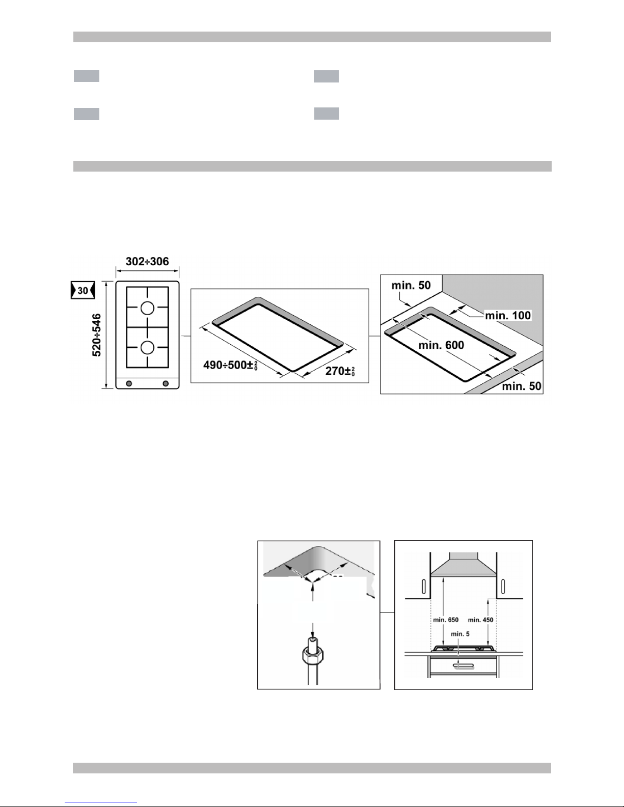
installation manual.
If an extractor fan is installed, you must
follow the installation manual's
instructions, always keeping a minimum
distance of 650 mm to the hob.
Preparation of kitchen unit
(fig. 1-2)
Make an appropriate size cut in the work
surface.
If the hob is electric or mixed (gas and
electricity) and there is no oven below,
place a non-flammable separator (e.g.
metal or plywood) 10 mm from the
bottom of the hob. This will prevent
access to the base of the hob.
If the hob is gas, it is recommendable to
place the separator at the same
distance.
On wood work surfaces, varnish the
cutting surfaces with a special glue. This
protects them from moisture which could
collect under the work surface.
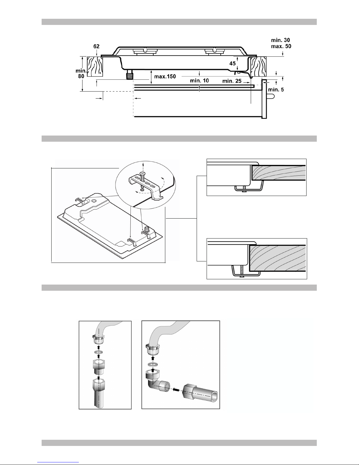
Installation of appliance
The clips and the adhesive seal
(underside of the hob) are factory-fitted:
do not under any circumstances remove
them. The seal ensures that the entire
work surface will be watertight, and
prevents water seepage.
In order to fit the appliance into the
kitchen unit, first place the hob in the
correct position then loosen each of the
clips so that they all turn freely (it is not
necessary to completely undo them).
Insert and centre the hob.
Press the sides of the hob until it is
supported around its entire perimeter.
Turn the clips and tighten them fully.
Fig. 3
Removal of hob
Turn off the appliance's electricity and
gas supply.
Unscrew the clips and proceed in the
reverse order to installation.
Gas connection (fig. 4)
The end of the inlet connection point of
the gas hob has a 1/2” (20.955 mm)
thread that allows for:
- fixed connection.
- connection using a flexible metal pipe
(L min. 1 m - max. 3 m). In this case, it is
necessary to insert the accessory
(427950) and the watertight seal
(034308) supplied between the manifold
outlet and the gas supply. Fig. 4a.
In this case, you must prevent the pipe
from coming into contact with moving
parts of the kitchen unit being inserted
(for example, a drawer) and prevent
access to any spaces which might
become obstructed.
If you need to connect the gas supply
horizontally, our Technical Assistance
Service can supply you with an L-tube
(code 173018) and a seal (code
034308). Fig. 4b.
Warning! If any connection is handled,
check the seal. Danger of leaks.
The manufacturer is not liable for any
connection leaking, after being handled.
Electric connection (fig. 5)
Check that the voltage and power of the
appliance are compatible with the
electrical installation.
The hobs are supplied with a power
cable with or without a wall socket plug.
Provide an omnipolar cut-off switch with
a minimum contact separation of 3 mm
(except for plug connections, if the user
has access to it).
Appliances with plugs must only be
connected to sockets that have earth
wires correctly installed.
This appliance is type “Y”: the supply
cable can only be changed by the
Technical Assistance Service and not
the user. The cable type and minimum
cross-section must be respected.
Changing the gas type
If the country's regulations allow, this
appliance can be adapted to other types
of gas (see specifications plate). The
components required for this are in the
transformation kit supplied (depending
on the model) available from our
Technical Assistance Service. The
following steps should be taken:
A) Changing the nozzles of the rapid,
semi-rapid and auxiliary burners on
the hob (fig. 6):
- Remove the pan supports, burner
covers and diffusers.
- Change the nozzles using the spanner
provided by our Technical Assistance
Service (code 424699), taking special
care to ensure that the nozzle does not
fall when it is removed from the burner or
when fitted.
Ensure that it is completely tightened in
order to guarantee the seal. Primary air
adjustment is not necessary with these
burners.
B) Changing the nozzles for doubleflame burners (fig. 7):
The glass panel and frame are fixed to
the rest of the hob using a clip mounting
system. The following steps must be
taken to remove the glass panel and
frame:
- Remove all the burner covers and pan
supports. Fig. 7a.
- Release the front clip fixing the
appliance to the kitchen unit by
removing the screw. Fig. 7b.
- Loosen the screws on the burners,
fig. 7c-7d, and remove the control knobs
from their respective housings.
Use the disassembly lever 483196
available from our Technical Assistance
Service. To release the front clips, apply
the lever in the area shown in figures 8
according to the hob model.
Never use the lever on glass edges
which have no trim or frame!
- To release the rear clips, carefully raise
the entire glass panel and frame, as in
fig. 8a.
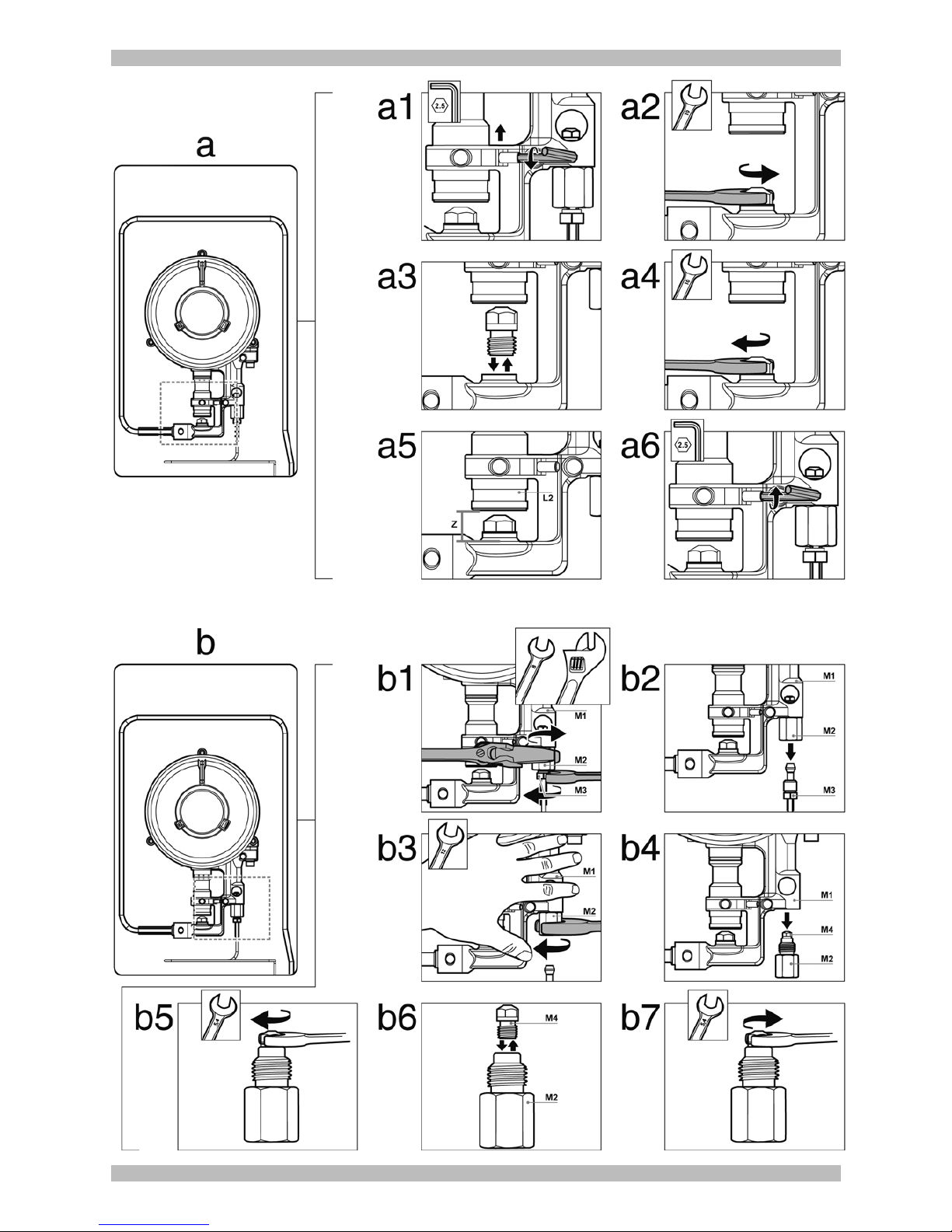
Changing the outer flame nozzle
(fig. 9a):
- Loosen the clamp screw to release the
bushing by moving it backwards to
access the main nozzle easily. Fig. a1.
Page 7

- Remove the outer flame nozzle by
turning it towards the left. Fig. a2-a3.
- Screw in the new outer flame nozzle.
Fig. a3-a4, as in table II.
- Adjust the distance of the airflow
adjusting bushing L2 according to the
value -Z- shown in table II. Fig. a5.
- Tighten the clamp screw. Fig. a6.
Changing the inner flame nozzle
(fig. 9b):
- Unscrew the part M3 from the threaded
part M2; to do this, hold the threaded
part in the opposite direction.
- Remove the pipe from the part M2.
Fig. b2.
- Disassemble the assembly of parts M2
and M4 from part M1. Fig. b3-b4.
- Remove the inner flame nozzle M4
from part M2. Fig. b5-b6.
- Screw in the new inner flame nozzle
M4, according to table II. Fig. b6-b7.
Refit all the components, proceeding in
the reverse order to removal.
Adjustment of the taps
Set the control knobs to minimum.
Remove the control knobs from the taps.
Fig. 10.
It has a flexible rubber valve reinforcing
ring. Simply press on this seal with the
tip of a screwdriver to allow access to
the tap adjusting screw. Fig. 10a.
Never remove the valve reinforcing
ring.
If the by-pass screw cannot be
accessed, disassemble the glass panel
and frame described in: Changing the
nozzles for double-flame burners. Fig. 7.
Adjust the minimum ring setting by
turning the by-pass screw using a flat
head screwdriver.
Depending on the gas to which your
appliance is going to be adapted, see
table III, carry out the corresponding
action:
A: firmly tighten the by-pass screws.
B: loosen the by-pass screws until the
gas flow from the burners is correct:
when adjusting the control knob
between maximum and minimum, the
burner does not go out, nor is there a
flame backdraught created.
C: the by-pass screws need to be
changed by an authorised installation
engineer.
D: do not touch the by-pass screws.
It is important that all the seals are
refitted to form a seal.
These devices are essential for the
correct operation of the appliance as
they prevent liquids and dirt from
entering the appliance.
Refit the control knobs.
Never remove the tap spindle (Fig 11).
In the event of a malfunction, change the
whole tap.
Warning! After finishing, the sticker
indicating the new type of gas must
be placed close to the specifications
plate.
DE
de
Lesen Sie die Gebrauchsanweisung für
das Gerät, bevor Sie es installieren und
benutzen.
Die Abbildungen in dieser Anleitung
dienen der Veranschaulichung.
Der Hersteller ist jeglicher
Verantwortung enthoben, wenn die
Bestimmungen dieses Handbuchs
nicht eingehalten werden.
Sicherheitshinweise zu
diesem Gerät
Alle Installations-, Regelungs- und
Umstellungsarbeiten auf eine andere
Gasart müssen von einem
autorisierten Fachmann und unter
Beachtung der jeweils anwendbaren
Regelungen und gesetzlichen
Vorgaben sowie der Vorschriften der
örtlichen Strom- und Gasversorger
vorgenommen werden.
Stellen Sie vor der Durchführung
jeglicher Arbeiten die Strom- und
Gaszufuhr ab.
Für Umstellungsarbeiten auf eine
andere Gasart empfehlen wir, den
Kundendienst zu rufen.
Dieses Gerät wurde ausschließlich für
die Verwendung in Privathaushalten
entworfen; eine kommerzielle oder
gewerbliche Nutzung ist nicht gestattet.
Dieses Gerät darf nicht auf Jachten oder
in Wohnwagen eingebaut werden. Die
Garantie gilt nur dann, wenn das Gerät
ausschließlich für seinen vorgesehenen
Zweck genutzt wird.
Überprüfen Sie vor der Installation des
Geräts, dass die örtlichen
Voraussetzungen (Gasart und -druck)
und die Geräteeinstellungen
miteinander kompatibel sind (siehe
Tabelle I). Die Bedingungen für die
Geräteeinstellung finden Sie auf dem
Etikett oder Typenschild.
Dieses Gerät darf nur an einem
ausreichend belüfteten Ort und nur in
Übereinstimmung mit den für die
Belüftung geltenden Bestimmungen und
Richtlinien eingebaut werden. Das
Gerät darf nicht an einen Schornstein
oder eine Abgasanlage angeschlossen
werden.
Das Netzkabel muss am Einbaumöbel
gut befestigt werden, damit es nicht mit
heißen Teilen des Backofens oder des
Kochfeldes in Berührung kommen kann.
Elektrische Geräte müssen immer
geerdet werden.
Hantieren Sie nie im Inneren des
Gerätes. Rufen Sie gegebenenfalls
unseren Kundendienst an.
Vor dem Einbau
Dieses Gerät entspricht Klasse 3 gemäß
DIN EN 30-1-1 für Gasgeräte:
Einbaugeräte.
Diese Geräte sind untereinander
und/oder mit herkömmlichen
Kochfeldern derselben Marke
kombinierbar, indem ein
Befestigungselement verwendet wird.
Weitere Informationen finden Sie im
Katalog.
Die neben dem Gerät befindlichen
Möbel müssen aus nicht brennbaren
Materialien sein. Die Schichtwerkstoffe
der Möbel sowie der sie
zusammenhaltende Leim müssen
hitzebeständig sein.
Dieses Gerät darf nicht über
Kühlschränken, Waschmaschinen,
Spülmaschinen oder ähnlichen Geräten
eingebaut werden.
Wenn Sie das Kochfeld auf einem
Backofen installieren, muss dieser über
eine Zwangsbelüftung verfügen.
Überprüfen Sie die Abmessungen des
Backofens in Ihrem
Installationshandbuch.
Wenn eine Dunstabzugshaube
angebracht wird, muss dies gemäß der
Montageanleitung und immer unter
Berücksichtigung eines vertikalen
Mindestabstandes von 650 mm zum
Kochfeld geschehen.
Vorbereitung des
Küchenmöbels (Abb. 1-2)
Nehmen Sie in der Arbeitsfläche einen
Ausschnitt mit den benötigten
Abmessungen vor.
Wenn es sich bei dem Kochfeld um ein
elektrisches oder gemischtes Kochfeld
(Gas und elektrisch) handelt und sich
kein Ofen darunter befindet, bringen Sie
einen Zwischenboden aus nicht
brennbarem Material (z.B. Metall oder
Sperrholz) 10 mm unter dem Boden des
Kochfeldes an. So wird ein Zugang zum
unteren Teil des Kochfeldes verhindert.
Wenn es sich bei dem Kochfeld um ein
Gaskochfeld handelt, wird empfohlen,
den Zwischenboden im selben Abstand
zum Kochfeld anzubringen.
Bei Arbeitsflächen aus Holz firnissen Sie
die Schnittflächen mit Spezialleim, um
sie vor Feuchtigkeit zu schützen.
Einbau des Gerätes
Die Klammern und die Klebedichtung
(unterer Rand des Kochfelds) werden im
Werk montiert; unter keinen Umständen
entfernen. Die Dichtung gewährleistet
die Abdichtung der gesamten
Arbeitsfläche und verhindert das
Eindringen von Flüssigkeiten.
Zur Befestigung des Geräts im
Einbaumöbel muss, nachdem das
Kochfeld in seine Position gebracht
worden ist, jede einzelne dieser
Klammern soweit losgeschraubt
werden, dass sie sich frei drehen
können (es ist nicht notwendig, sie völlig
abzuschrauben).
Fügen Sie das Kochfeld mittig ein.
Drücken Sie die Ränder solange nach
unten, bis der gesamte Rand aufliegt.
Drehen Sie die Klammern und ziehen
Sie diese fest an. Abb. 3.
Ausbau des Kochfeldes
Trennen Sie das Gerät von der Stromund Gasversorgung.
Schrauben Sie die Klammern auf und
folgen Sie den Einbauschritten in
umgekehrter Reihenfolge.
Page 8

Gasanschluss (Abb. 4)
Am Ende des Eingangsrohrs zum
Gaskochfeld befindet sich ein 1/2”
(20,955 mm) Gewinde. Dieses Gewinde
ermöglicht:
- einen Festanschluss.
- einen Anschluss mit einem flexiblen
Metallschlauch (L min. 1 m - max. 3 m).
In diesem Fall müssen das Zubehörteil
(427950) sowie die Dichtung (034308)
(beide mitgeliefert) zwischen dem
Auslass der Sammelleitung und dem
Gasanschluss angebracht werden.
Abb. 4a.
In diesem Fall ist zu vermeiden, dass
dieser Schlauch in Kontakt zu den
beweglichen Teilen der Einbaueinheit
gelangt (z. B. mit einer Schublade), und
er darf nicht durch Öffnungen verlegt
werden, die verschlossen werden
könnten.
Wenn ein horizontaler Gasanschluss
hergestellt werden soll, liefert Ihnen
unser technischer Kundendienst einen
Winkel mit der Teilenummer 173018,
sowie eine Dichtung mit der
Teilenummer 034308. Abb. 4b.
Hinweis! Nach Arbeiten an einer
Anschlussstelle, diese immer auf
Dichtheit prüfen.
Gasaustrittsgefahr!
Der Hersteller übernimmt für den
Gasaustritt an einer Anschlussstelle, an
der zuvor hantiert wurde, keine
Verantwortung.
Elektrischer Anschluss
(Abb. 5)
Prüfen Sie, ob Spannung und
Nennleistung des Geräts mit der
elektrischen Installation
übereinstimmen.
Die Kochfelder werden mit Netzkabel
mit oder ohne Stecker ausgeliefert.
Es muss ein allpoliger Trennschalter mit
mindestens 3 mm Kontaktabstand
angebracht werden (außer bei
Anschluss an eine frei zugängliche
Steckdose).
Mit Stecker ausgestattete Geräte dürfen
nur in vorschriftsmäßig angebrachte,
geerdete Steckdosen gesteckt werden.
Das Gerät gehört zum Typ "Y": Das
Zuleitungskabel darf nicht vom
Benutzer, sondern nur vom
Kundendienst ausgetauscht werden.
Sowohl Kabeltyp als auch minimaler
Querschnitt müssen berücksichtigt
werden.
Umstellung auf eine andere
Gasart
Wenn die einschlägigen Bestimmungen
des jeweiligen Landes dies erlauben,
kann dieses Gerät auf andere Gasarten
umgestellt werden (siehe Typenschild).
Die hierfür notwendigen Teile befinden
sich im mitgelieferten Umbaukit (je nach
Modell), das über den Kundendienst
bezogen werden kann. Es müssen
folgende Schritte befolgt werden:
A) Austausch der Düsen der
schnellen und mittelschnellen
Brenner sowie der Sparbrenner des
Kochfeldes (Abb. 6):
- Die Roste, Deckel und Brennerkörper
abnehmen.
- Tauschen Sie die Düsen mit dem über
unseren Kundendienst erhältlichen
Schlüssel mit der Teilenummer 424699
aus, wobei besonders darauf zu achten
ist, dass die Düse beim Herausnehmen
oder Befestigen im Brenner nicht
abbricht.
Stellen Sie sicher, sie bis zum Anschlag
eingedreht zu haben, um eine gute
Abdichtung zu erreichen. Bei diesen
Brennern muss keine Einstellung der
Primärluft vorgenommen werden.
B) Austausch der
Doppelbrennerdüsen (Abb. 7)
Die Einheit aus Glas und Profilen ist
über ein Clip-Befestigungssystem mit
dem restlichen Kochfeld verbunden.
Zum Abnehmen des Komplexes aus
Glas und Profilen wie folgt vorgehen:
- Die Roste, Deckel und Brennerkörper
abnehmen. Abb. 7a.
- Durch Herausziehen der Schraube die
Halteklammer Gerät-Möbel lösen.
Abb. 7b.
- Die Schrauben der Brenner lösen,
Abb. 7c-7d und die Bedienknebel aus
den jeweiligen Aussparungen
herausziehen.
Den bei unserem Kundendienst
erhältlichen Demontagehebel,
Teilenummer 483196, verwenden. Zum
Lösen der vorderen Clip-Befestigung
den Hebel in dem Bereich ansetzen, der
in den Abbildungen 8 je nach Modell
Ihres Kochfeldes markiert ist.
Setzen Sie niemals den Hebel über
Glaskanten an, die keine Profilleisten
oder Rahmen haben!
- Zum Lösen der hinteren ClipBefestigung die Einheit aus Glasscheibe
und Profilen entsprechend der Abb. 8.
vorsichtig anheben.
Austausch der Düse der äußeren
Flamme (Abb. 9a):
- Die Befestigungsschraube lösen, um
den Luftflussregler freizulegen und
somit zurückschieben zu können, damit
die Hauptdüse leicht zugänglich ist.
Abb. a1.
- Die Düse der äußeren Flamme durch
Drehung nach links abnehmen. Abb. a2a3.
- Die neue Düse der äußeren Flamme
einschrauben. Abb. a3-a4, wie
abgebildet II.
- Den Abstand im Luftflussregler L2
gemäß dem Wert -Z- einstellen; Wert
aus Tabelle II. Abb. a5.
- Die Befestigungsschraube anziehen.
Abb. a6.
Austausch der Düse der inneren
Flamme (Abb. 9b):
- Das Teil M3 vom Gewindestück M2
abschrauben und dabei das
Gewindestück in Gegenrichtung
blockieren.
- Die Zuleitung des Teils M2
herausziehen. Abb. b2.
- Die Einheit M2-M4 von Teil M1
abbauen. Abb. b3-b4.
- Die Düse der inneren Flamme M4 vom
Teil M2 abschrauben. Abb. b5-b6.
- Die neue Düse der inneren Flamme M4
einschrauben, wie abgebildet II.
Abb. b6-b7.
Die Montage sämtlicher Komponenten
in umgekehrter Reihenfolge der
Demontage vornehmen.
Einstellung der Gashähne
Drehen Sie die Bedienknebel auf die
minimale Position.
Ziehen Sie die Schalter der Gashähne
ab. Abb. 10.
Es wird ein innerer Dichtring aus
flexiblem Gummi sichtbar. Es ist
ausreichend, diese mit der
Schraubenzieherspitze beiseite zu
drücken, um an die Einstellschraube des
Gashahns zu gelangen. Abb. 10a.
Bauen Sie die Knebeldichtungen
niemals aus.
Wenn Sie nicht an die BypassSchrauben gelangen sollten, bauen Sie
die Einheit aus Glasscheibe und Profilen
aus, wie im folgenden Abschnitt
beschrieben: “Austausch der
Doppelbrennerdüsen” Abb. 7.
Stellen Sie die minimale Gaszufuhr ein,
indem Sie die Bypass-Schraube mit
einem Schlitzschraubenzieher drehen.
Je nach Gasart, auf die Sie umstellen ,
siehe Tabelle III, müssen
entsprechende Schritte durchgeführt
werden:
A: die Kleinbranddüsen ganz anziehen.
B: die Kleinbranddüsen bis zum
korrekten Gasaustritt an den Brennern
lockern:
stellen Sie sicher, dass bei einer
Umstellung des Bedienknebels von der
maximalen auf die minimale Position,
die Flamme nicht ausgeht und nicht
zurückschlägt.
C: die Kleinbranddüsen sollten von
einem autorisierten Fachmann
ausgetauscht werden.
D: die Kleinbranddüsen nicht
manipulieren.
Es ist wichtig, dass alle
Knebeldichtungen richtig angebracht
sind, um die Dichtheit zu gewährleisten.
Die Dichtungen sind für den fehlerfreien
Betrieb des Geräts unerlässlich, da sie
das Eindringen von Flüssigkeiten und
Schmutz ins Geräteinnere verhindern.
Stecken Sie die Bedienknebel
wieder auf.
Bauen Sie niemals die Achse des
Gashahns aus (Abb. 11). Bei einer
Störung sollte der komplette Gashahn
ersetzt werden.
Achtung! Bringen Sie den Aufkleber
mit der umgestellten Gasart in der
Nähe des Typenschildes an.
ru
Перед началом монтажа и
эксплуатации внимательно изучите
руководство к Вашему
электроприбору.
Приведенные в данном руководстве по
монтажу рисунки являются
ориентировочными.
Page 9

При невыполнении инструкций,
содержащихся в данном
руководстве, производитель
освобождается от всякой
отетственности.
Инструкции по безопасному
использованию
Все операции по установке, наладке
и адаптации к другому виду газа
должны проводиться
сертифицированным сециалистом
в соответствии с действующими
нормами и законодательством, а
также с предписаниями местных
газо и электроснабжающих
компаний.
Перед проведением любых
действий необходимо перекрыть
подачу газа и электроэнергии к
данному электроприбору.
Для адаптации прибора к другому
виду газа рекомендуется связаться
с сервисным центром.
Данный прибор предназначен
исключительно для бытового
использования и не может
применяться в промышленных или
коммерческих целях. Данный прибор
нельзя устанавливать на яхтах или в
автокемперах. Гарантия
производителя действительна только
в случае использования прибора по
назначению.
Перед установкой необходимо
проверить, соответствуют ли
характеристики подаваемого в Вашем
регионе газа (вид газа и давление)
настройкам прибора (см. таблицу I).
Параметры настройки прибора
указаны на этикетке и в табличке с
характеристиками.
Данный прибор можно устанавливать
только в хорошо проветриваемом
месте, в соответствии с действующими
нормами и инструкциями относительно
вентиляции помещений. Данный
прибор нельзя подсоединять к
дымоходу для отвода дымовых газов.
Кабель питания необходимо закрепить
на тумбе, чтобы не допускать его
соприкосновения с нагревающимися
деталями духового шкафа или
варочной панели.
Приборы, работающие от электросети,
должны обязательно подсоединяться к
заземлению.
Нельзя вносить изменения во
внутренние элементы прибора. Если
необходимо произвести ремонт,
обратитесь в наш сервисный центр.
Перед установкой
Данный прибор относится к третьему
классу защиты по стандарту EN 30-1-1
для газовых приборов: встроенное
оборудование.
Данные панели могут
комбинироваться между собой и/или с
обычными варочными панелями этой
же марки с помощью соединительного
устройства.
Его можно найти в нашем каталоге.
Мебель, соприкасающаяся с варочной
панелью, должна быть изготовлена из
невоспламеняющихся материалов.
Облицовочные слоистые покрытия и
закрепляющий их клей должны быть
термостойкими.
Данный прибор нельзя устанавливать
над холодильниками, стиральными
машинами, посудомоечными
машинами и дугой подобной техникой.
Чтобы варочную панель можно было
установить над духовым шкафом, в
нем должна иметься система
принудительнй вентиляции.
Проверьте размеры духового шкафа в
соответствующем руководстве по
монтажу.
При монтаже вытяжного устройства
необходимо следовать инструкциям
соответствующего руководства по
монтажу, следя за тем, чтобы
расстояние от вытяжки до варочной
панели по вертикали было не менее
650 мм.
Подготовка тумбы
(рис. 1-2)
Проделайте в столешнице отверстие
нужных размеров.
Если у Вас электрическая или
комбинированная (газовые и
электрические конфорки) варочная
панель, и духовой шкаф под ней не
устанавливается, необходимо
поставить под ней перегородку из
невоспламеняющегося материала
(например, из металла или фанерного
листа) на расстоянии 10 мм от
основания варочной панели. Таким
образом Вы перекроете доступ к
нижней части панели.
В случае газовой варочной панели
также рекомендуется установить
перегородку на том же расстоянии.
Если столешница выполнена из
дерева, покройте поверхность среза
специальным герметиком, чтобы
защитить ее от действия влаги.
Монтаж прибора
Крепления и клеящаяся прокладка (по
нижнему краю варочной панели)
устанавливаются на фабрике, ни в
коем случае не снимайте их.
Прокладка гарантирует
влагонепроницаемость всей
столешницы и препятствует
фильтрации влаги.
Чтобы закрепить варочную панель в
тумбе после того, как панель
установлена в рабочее положение,
Вам потребется раскрутить все
крепления, чтобы они свободно
вращались (откручивать их до конца не
обязательно).
Вставьте варочную панель в
подготовленное отверстие и
выровняйте ее.
Нажмите на края панели так, чтобы
варочная панель оперлась на край
столешницы по всему периметру.
Разверните крепления и туго затяните
их. Рис. 3.
Демонтаж варочной панели
Отсоедините прибор от электросети и
от газопровода.
Открутите винты креплений и
повторите действия, выполненные во
время монтажа, в обратном порядке.
Подключение газа (рис. 4)
На конце впускного патрубка варочной
панели имеется резьба диаметром 1/2”
(20,955 mm), позволяющая
обеспечить:
- жесткое соединение.
- соединение с гибким металлическим
шлангом (L min. 1 m - max. 3 m). В этом
случае необходимо вставить между
концом входного патрубка и трубой
подачи газа дополнительную деталь
(427950) и герметичную прокладку
(034308), поставляемые с варочной
панелью. Рис. 4a.
В этом случае необходимо исключить
соприкосновение шланга с
подвижными частями мебели, в
которую встраивается варочная
панель (например, с выдвижными
ящиками), а также прохождение
шланга в местах, которые могут
оказаться загроможденными.
Если необходимо сделать подводку
газа горизонтально, в нашем
сервисном центре можно приобрести
колено трубы с артикулом 173018, а
также прокладку с артикулом 034308.
Рис. 4b.
Внимание! После внесения
изменений в соединительную
конструкцию проверьте ее
герметичность.
Существует опасность утечки газа!
Производитель не несет
ответственности за утечку газа в
соединениях, выполненных
пользователем или исполителем
монтажных работ.
Подключение к
электросети (рис. 5)
Проверьте, чтобы напряжение и
мощность прибора соответствовали
Вашей электросети.
Варочные панели поставляются с
кабелем питания, который может не
иметь штепсельной вилки.
Необходимо предусмотреть
размыкающее устройство для всех
полюсов прибора с воздушным
зазором между контактами не менее 3
мм (за исключением случаев
подсоединения с использованием
розетки, если пользователь имее к ней
доступ).
Приборы, снабженные штепсельной
вилкой, можно подключать только к
розеткам с правильно установленным
заземлением.
Данный прибор относится к классу “Y”:
не допускается замена кабеля питания
пользователем, это может делат
только сервисный центр. Необходимо
учитывать тип кабеля и его
минимальное сечение.
Адаптация к другому виду
газа
Если это разрешено нормами Вашей
страны, данный прибор можно
настроить для использования с
другими видами газа (см. табличку с
характеристиками). Необходимые для
этого детали находятся в
поставляемом с некоторыми
моделями наборе для адаптации,
который также можно приобрести в
нашем сервисном центре. Необходимо
выполнть следующие действия:
A) Замена жиклеров горелок
быстрой, полубыстрой и
вспомогательной конфорки
варочной панели (рис. 6):
- Снимите решетки, крышки горелок и
рассекатели.
- Замените жиклеры с помощью ключа,
имеющегося в продаже в нашем
сервисном центре (артикул 424699),
тщательно седя за тем, чтобы в
процессе снятия жиклера или его
закрепления на горелке он не
соскочил.
Убедитесь в том, что жиклеры
тщательно прижаты, чтобы обеспечить
герметичность горелок. В данных
горелках е нужно производить
регулировку подачи первичного
воздуха.
B) Замена жиклеров на горелках
конфорок двойного пламени
(рис. 7):
Блок стекла с профилями фиксируется
на варочной панели с помощью винтов
и креплений. Чтобы снять блок стека с
профилями, следуйте данным
указаниям:
Page 10

- Снимите все крышки горелок и
решетки. Рис. 7a.
- Высвободите переднюю деталь
крепления прибора к тумбе, вытащив
винт. Рис. 7b.
- Открутите винты горелок, рис. 7c-7d,
и вытащите ручки управления из их
гнезд.
Используйте рычаг для демонтажа
483196, который можно приобрести в
нашем сервисном центре. Чтобы
отсоединить детали крепления в
передней части, воспользуйтесь
рычагом в точке, отмеченной на
рисунке номер 8, соответствующем
модели Вашей варочной панели.
Никогда не прикладывайте рычаг к
краям стеклянного блока, которые
не защищены профилем или рамой!
- Чтобы отсоединить детали крепления
в задней части панели, осторожно
поднимите блок стекла с профилями,
как это показано на рис. 8a.
Замена жиклера внешнего кольца
пламени (рис. 9a):
- Открутите крепежный винт, чтобы
сдвинуть втулку и получить доступ к
главному жиклеру. Рис. a1.
- Вытащите жиклер внешнего кольца
пламени, повернув его влево.
Рис. a2-a3.
- Закрутите новый жиклер внешнего
кольца пламени (рис. a3-a4), в
соответствии с таблицей II.
- Отрегулируйте расстояние до втулки
регулятора подачи воздуха L2 в
соответствии с параметром Z,
указанным в таблице II. Рис. a5.
- Закрутите крепежный винт. Рис. a6.
Замена жиклера внутреннего
кольца пламени (рис. 9b):
- Открутите деталь M3 от нарезной
детали M2. Для этого придерживайте
нарезную деталь, оказывая на нее
давлени в противоположном
направлении.
- Извлеките трубу из детали M2.
Рис. b2.
- Открутите соединенные детали M2M4 от детали M1. Рис. b3-b4.
- Извлеките жиклер внутреннего
кольца пламени M4 из детали M2. Рис.
b5-b6.
- Закрутите новый жиклер внутреннего
кольца пламени M4, в соответствии с
таблицей II.
Рис. b6-b7.
Снова соберите все детали, повторив
в обратном порядке те же действия,
что и в процессе демонтажа.
Настройка кранов
Установите ручки управления в
положение минимального огня.
Снимите ручки кранов. Рис. 10.
Вы найдете уплотнительную
прокладку из эластичной резины. Для
того, чтобы открыть доступ к
байпасному винту, достаточно нажать
на нее кончиком отвертки. Рис. 10a.
Никогда не снимайте прокладку.
Если Вы не можете найти доступ к
байпасному винту, демонтируйте блок
стекла с профилями так, как это описан
в разделе Замена жиклеров на
горелках конфорок двойного пламени.
Рис. 7.
Отрегулируйте минимальную
величину пламени, повернув
байпасный винт с помощью плоской
отвертки.
В зависимости от вида газа, к которому
Вы адаптируете свой прибор (см.
таблицу III), выполните следующие
действия:
A: закрутите регулировочные винты до
отказа.
B: ослабьте байпасные винты, пока газ
не будет правильно выходить из
горелок:
убедитесь, чтобы при повороте ручки
управления от максимальной до
минимальной отметки горелки не гасли
и не происходило возврата пламени.
C: байпасные винты нужно заменить в
нашем сервисном центре.
D: никаких действий с байпасными
винтами производить не нужно.
Для обеспечения герметичности
важно, чтобы все уплотнительные
прокладки находились на своем месте.
Эти элементы необходимы для
правильной работы прибора, так как
препятствуют проникновению воды и
грязи внутрь варочной панели.
Снова установите ручки управления.
Никогда не демонтируйте вал газового
крана (рис. 11). В случае его
повреждения замените весь кран.
Внимание! После окончания работы
наклейте рядом с таблицей с
характеристиками варочной панели
этикетку с казанием нового вида
газа.
pt
Leia as instruções do aparelho antes de
proceder à sua instalação e uso.
Os gráficos são representados nestas
Instruções de montagem a título
orientativo.
O fabricante fica isento de toda a
responsabilidade caso não se
cumpram as disposições constantes
deste manual.
Indicações de segurança
Todos os trabalhos de instalação,
regulação e adaptação a outro tipo de
gás devem ser realizados por um
técnico autorizado, respeitando as
regulamentações e legislação
aplicáveis, bem como o estipulado
pelas empresas locais de
electricidade e de gás.
Antes de qualquer procedimento,
corte a alimentação eléctrica e de gás
do aparelho.
Recomenda-se chamar o Serviço
Técnico para a adaptação a outro tipo
de gás.
Este aparelho foi unicamente concebido
para utilização doméstica, não
podendo, por isso, ser utilizado para fins
comerciais ou profissionais. Este
aparelho não pode ser instalado em
iates ou caravanas. A garantia apenas
será válida caso o aparelho seja
utilizado correctamente e para os fins a
que se destina.
Antes da instalação deve comprovar se
as condições de distribuição local
(natureza e pressão do gás) e a
regulação do aparelho são compatíveis
(ver tabela I). As condições de
regulação do aparelho estão indicadas
na etiqueta ou na placa de
características.
Este aparelho só pode ser instalado
num local bem ventilado e cumprindo
com os regulamentos e as disposições
em vigor relativas à ventilação. Este
aparelho não deve ser ligado a um
equipamento extractor de produtos de
combustão.
O cabo de alimentação deve ser fixo ao
móvel para evitar que entre em contacto
com as partes quentes do forno ou da
placa de cozedura.
Os aparelhos com alimentação eléctrica
devem ser obrigatoriamente ligados à
terra.
Não manipule o interior do aparelho. Se
necessário, contacte o nosso Serviço de
Assistência Técnica.
Antes da instalação
Este aparelho corresponde à classe 3,
segundo a norma EN 30-1-1 para
aparelhos a gás: aparelho embutido
num móvel.
Estes aparelhos podem ser combinados
entre si e/ou com placas vitrocerâmicas
convencionais da mesma marca,
através da utilização do acessório de
união.
Consulte o catálogo.
Os móveis que fiquem próximos do
aparelho devem ser feitos de materiais
não inflamáveis. Os revestimentos
estratificados e a cola que os fixa devem
ser resistentes ao calor.
Este aparelho não pode ser instalado
sobre frigoríficos, máquinas de lavar
roupa, máquinas de lavar loiça ou
aparelhos similares.
Para instalar a placa de cozedura sobre
um forno, este deve incluir um
mecanismo de ventilação forçada.
Verifique as dimensões do forno no seu
manual de instalação.
Se instalar um extractor, deve ter em
conta o respectivo manual de
instalação, respeitando sempre uma
distância vertical mínima de 650 mm da
placa de cozedura.
Preparação do móvel
(fig. 1-2)
Realize um corte das dimensões
necessárias na superfície de trabalho.
Se a placa de cozedura for eléctrica ou
mista (gás e electricidade) e se não
houver um forno por baixo da mesma,
coloque um separador de material não
inflamável (por ex. de metal ou madeira
contraplacada) a 10 mm da base da
placa de cozedura. Assim impede o
acesso à parte inferior desta.
Se a placa de cozedura for a gás,
recomenda-se que coloque o separador
à mesma distância.
Em superfícies de trabalho de madeira,
envernize as superfícies de corte com
uma cola especial para as proteger da
humidade.
Instalação do aparelho
Os grampos e a junta adesiva (borda
inferior da placa de cozedura) vêm
instalados da fábrica e não devem ser
retirados em circunstância alguma. A
junta garante a impermeabilização de
toda a superfície de trabalho e evita
qualquer filtração.
Para a fixação do aparelho no móvel de
encastramento, deve, uma vez
colocada a bancada na respectiva
posição de trabalho, desaparafusar
cada um dos grampos até fazê-lo rodar
Page 11

livremente (não sendo necessário
desaparafusar totalmente).
Encastre e centre a placa de cozedura.
Pressione sobre os seus extremos até
que se apoie em todo o seu perímetro.
Gire os grampos e aperte-os bem.
Fig. 3.
Desmontagem da placa de
cozedura
Desligue o aparelho das tomadas
eléctricas e de gás.
Desaparafuse os grampos e proceda de
modo inverso ao da montagem.
Conexão de gás (fig. 4)
A extremidade do colector de entrada da
placa de cozedura a gás está equipada
com uma rosca de 1/2” (20,955 mm),
que permite:
- Realizar uma conexão rígida.
- Realizar a conexão com um tubo
flexível metálico (L min. 1 m - max. 3 m).
Neste caso, é necessário intercalar o
acessório (427950) e a junta de
estanquicidade (034308) fornecidos
entre a saída do colector e a entrada de
gás. Fig. 4a.
Neste caso, deve-se evitar o contacto
deste tubo com qualquer parte móvel da
unidade onde se embutirá o aparelho
(por exemplo, uma gaveta), bem como a
sua passagem por onde pudesse ficar
obstrudo.
Para realizar a conexão de gás na
horizontal, o nosso serviço de
assistência técnica disponibiliza um
cotovelo (código 173018) e uma junta
(código 034308). Fig. 4b.
Atenção! Se manipular qualquer
conexão, verifique a estanquicidade.
Perigo de fuga!
O fabricante não se responsabiliza se
alguma conexão apresentar fugas
depois de ter sido manipulada.
Conexão eléctrica (fig. 5).
Verifique se a voltagem e a potência do
aparelho são compatíveis com a
instalação eléctrica.
As placas de cozedura são fornecidas
com um cabo de alimentação com ou
sem ficha.
Deve-se prever um interruptor
omnipolar com uma abertura de
contacto mínima de 3 mm (excepto em
ligações com ficha se esta estiver
acessível ao utilizador).
Os aparelhos fornecidos com ficha só
devem ser ligados a tomadas de terra
devidamente instaladas.
Este aparelho é do tipo “Y”: o cabo de
entrada não pode ser mudado pelo
utilizador, só o Serviço Técnico deve
fazê-lo. Deve-se sempre respeitar a
secção mínima e o tipo de cabo.
Mudança do tipo de gás
Se as regulamentações do país o
permitirem, este aparelho pode ser
adaptado a outros tipos de gás (ver
placa de características). As peças
necessárias para tal estão incluídas na
bolsa de transformação fornecida
(consoante o modelo), também
disponível no nosso Serviço de
Assistência Técnica. Os passos a seguir
são os seguintes:
A) Mudança dos injectores dos
queimadores rápido, semi-rápido e
auxiliar da placa de cozedura (fig. 6):
- Retire as grelhas, as tampas de
queimador e os difusores.
- Mude os injectores usando a chave
disponível através do nosso serviço de
assistência técnica, com o código
424699, tendo especial atenção para
que não se solte o injector ao retirá-lo ou
fixá-lo no queimador.
Aperte bem os injectores para garantir a
hermeticidade. Nestes queimadores
não é necessário realizar a regulação do
ar primário.
B) Mudança dos injectores para os
queimadores de chama dupla (fig. 7):
O conjunto de vidro + perfis está fixo na
restante parte da placa de cozedura
através de um sistema de fixação por
clipes. Para retirar o conjunto
vidro + perfis, realize o seguinte
procedimento:
- Retire todas as tampas de queimador
e grelhas. Fig. 7a.
- Solte o grampo de fixação frontal do
aparelho-móvel retirando o parafuso.
(Fig. 7b).
- Desaperte os parafusos dos
queimadores (fig. 7c-7d) e retire os
comandos dos respectivos alojamentos.
- Utilize a alavanca de desmontagem
483196 disponível através do nosso
serviço de assistência técnica. Para
soltar o clipe frontal, introduza a
alavanca na zona indicada nas figuras 8
consoante o modelo da sua placa de
cozedura.
Nunca introduza a alavanca nos
cantos do vidro sem perfil nem
moldura!
- Para soltar o clipe posterior, levante
cuidadosamente o conjunto de
vidro + perfis como indicado na fig. 8a.
Mudança do injector de chama
externo (fig. 9a):
- Desaperte o parafuso de fixação para
soltar a vedação para trás de modo a
aceder facilmente ao injector principal.
Fig. a1.
- Retire o injector de chama externo
rodando-o para a esquerda. Fig. a2-a3.
- Enrosque o novo injector de chama
externo. Fig. a3-a4, consoante a
tabela II.
- Ajuste a distância na vedação
reguladora do fluxo de ar L2 de acordo
com o valor -Z- indicado na tabela II.
Fig. a5.
- Aperte o parafuso de fixação. Fig. a6.
Mudança do injector de chama
interno (fig. 9b):
- Desenrosque a peça M3 da peça
roscada M2, mantendo esta última em
sentido contrário.
- Retire o tubo da peça M2. Fig. b2.
- Desmonte o conjunto M2-M4 da
peça M1. Fig. b3-b4.
- Retire o injector de chama interno M4
da peça M2. Fig. b5-b6.
- Enrosque o novo injector de chama
interno M4, consoante a tabela II.
Fig. b6-b7.
Realize a montagem de todos os
componentes de forma inversa à do
processo de desmontagem.
Regulação das torneiras
Coloque os comandos na sua posição
mínima.
Retire os comandos das torneiras
(fig. 10).
Inclui uma anilha de borracha flexível.
bastando pressioná-lo com a ponta da
chave de venda para que se libere o
acesso ao parafuso de regulação da
torneiro. Fig. 10a.
Nunca desmonte o retentor.
Se não encontrar o acesso ao parafuso
by-pass, desmonte o conjunto de
vidro + perfis descrito em: Mudança dos
injectores para os queimadores de
chama dupla. Fig. 7.
Regule a chama mínima rodando o
parafuso by-pass através de uma chave
de fendas de ponta plana.
Consoante o gás ao qual vai adaptar o
aparelho (ver tabela III), efectue a acção
correspondente:
A: apertar bem os parafusos bypass.
B: afrouxar os parafusos bypass até
conseguir a saída de gás correcta dos
queimadores:
verifique se, ao ajustar o comando entre
o máximo e o mínimo, o queimador não
se apaga nem ocorre um retrocesso da
chama.
C: os parafusos bypass devem ser
substituídos por um técnico autorizado.
D: não manipular os parafusos bypass.
É importante que todos os retentores
estejam colocados para se poder
assegurar a estanquicidade. Estes
dispositivos são imprescindíveis para o
correcto funcionamento do aparelho, já
que impedem a entrada de líquido e a
formação de sujidade no interior do
aparelho.
Volte a colocar os comandos.
Nunca desmonte o eixo da torneira
(Fig. 11). Em caso de avaria, deve-se
substituir todo o conjunto que conforma
a torneira.
Atenção! Ao terminar, coloque a
etiqueta adesiva, indicando o novo
tipo de gás, próximo da placa de
características.
Page 12

I
COUNTRIES/GASES GAS ADJUSTED MODEL TYPE
∑Qn (kW)
G20
,
G25
G20
m3/h
)
G25
m3/h
)
G30
/h
)
G31
(g
/h
)
WV~ Hz
GK11TGC-798.3.49 HSE-K3FW130 6,00 0,572 0,665 435 428 0,8 W 220-240 V~ 50/60 Hz
GK21TGC-797.3.49 HSE-K3F2030 4,70 0,448 0,521 341 335 0,8 W 220-240 V~ 50/60 Hz
II
GAS mbar Qn (Kw) m3/h g/h Qr (kW)
G20 20 72 1,10 0,105 - 27 0,30
G20 25 65 1,10 0,105 - 27 0,30
G25 20 79 1,10 0,122 - 27 0,30
G25 25 78 1,10 0,122 - 27 0,30
G30 29 53 1,10 - 80 27 0,33
G30 50 48 1,10 - 80 24 0,33
G31 37 53 1,10 - 79 27 0,33
G20 20 125 2,80 0,267 - 39 0,60
G20 25 109 2,80 0,267 - 39 0,60
G25 20 141 2,80 0,310 - 39 0,60
G25 25 118 2,80 0,310 - 39 0,60
G30 29 83 2,80 - 203 39 0,60
G30 50 74 2,80 - 203 33 0,60
G31 37 83 2,80 - 200 39 0,60
G20 20 93 1,90 0,181 - 29 0,40
G20 25 91 1,90 0,181 - 29 0,40
G25 20 105 1,90 0,211 - 29 0,40
G25 25 104 1,90 0,211 - 29 0,40
G30 29 70 1,90 - 138 29 0,35
G30 50 60 1,90 - 138 25 0,35
G31 37 70 1,90 - 136 29 0,35
G20 20 171 6 0,572 - - -
G20 20 69 - - - 27 0,30
G20 25 163 6 0,572 - - -
G20 25 62 - - - 27 0,30
G25 20 194 6 0,665 - - -
G25 20 76 - - - 27 0,30
G25 25 180 6 0,665 - - -
G25 25 72 - - - 27 0,30
G30 29 115 6 - 435 - -
G30 29 47 - - - 27 0,30
G30 50 100 6 - 435 - -
G30 50 42 - - - 25 0,30
G31 37 115 6 - 428 - -
G31 37 47 - - - 27 0,30
G20/20 G20/25 G25/20 G25/25 G30/29 G30/50 G31/37
G20/20 DDDACA
G20/25 D DDACA
G25/20 DD DACA
G25/25 DDD ACA
G30/29 BBBB CD
G30/50 CCCCC C
G31/37 BBBBDC
III
G-20/20 mbar ERDGAS / ERDGAS E /
NATURGAS / GAS NATURAL /
MAAKAASU NATURGAS / Φυοικ_αεοιο /
NATURAL GAS / GAS METANO / GAS
NATUREL / GAZ ZIEMNY
G-20/G-25-20/25 mbar AARDGAS / GAZ
NATUREL LACQ
G-20/20 mbar ERDGAS / ERDGAS E /
NATURGAS / GAS NATURAL /
MAAKAASU NATURGAS / Φυοικ_αεοιο /
NATURAL GAS / GAS METANO / GAS
NATUREL / GAZ ZIEMNY
G-20/G-25-20/25 mbar AARDGAS / GAZ
NATUREL LACQ
Cat.
Cat.
II
II
2E+3+
2H3B/P
20-50
20/25-28-30/37
AT
II
2H3B/P
20-30
I
2E
20
II
2H3+
IT/PT
20-30/37
LV
I
2H
20
DE
20-50
II
2H3+
20-28/37
BE/FR
ES/GB/GR/IE
LU/PL
II
2ELL3B/P
DK/FI/SE/CZ/SK/EE/LT/SI/RO/BG/NO/CY
p(mbar)
p(mbar)
BE/FR
Cat.
Cat.
II
II
2E+3+
2H3B/P
20-50
20/25-28-30/37
AT
II
2H3B/P
20-30
II
2H3+
IT/PT
20-30/37
LV
I
2H
20
II
2ELL3B/P
DE
20-50
II
2H3+
20-28/37
III
1a2H3B/P
DK
8-20-30
III
1ab2H3B/P
SE
8-20-30
LU/PL
I
20
2E
ES/GB/GR/IE
FI/CZ/SK/EE/LT/SI/RO/BG/NO/CY
p(mbar)
p(mbar)
Cod. 9000526141 D
J302.110-2
 Loading...