

Installation instructions
J004133-R12
For flush installation of a frameless hob
with cement set and sealing strips
J004133-R12
12/06/2018
Validity
These installation instructions apply to the following models:
005, 008, 009, 027, 028, 031, 032, 039–041, 226, 307, 527, 533, 878, 973–979, 84A, 87A–91A, 94A–97A, 31001–31200
Accessories
Designation Article no.
Instant adhesive for installation of the steel angle (50 ml) B11657
Straight mixing nozzle, 10x B11656
TREMCLEAN isopropyl alcohol (1000 ml) 1056609
Black silicone FA880 (310 ml) B11555
Anthracite silicone FA880 (310 ml) B11556
White silicone FA880 (310 ml) 1031313
Stone grey silicone FA880 (310 ml) 1031314
Marble smoothing agent AA320 (1000 ml) B11557
Fugenboy set (silicone finishing tool set) B75158
In case of doubt as to the suitability of cement set materials, especially when using them for the first time, we recommend that
you carry out adhesion trials on test pieces or at non-visible locations.
Sealing strip set included with the hob
Art. no. Characteristics Thickness × width Length per roll
H63283 Sealing strip, open-cell (soft) 5mm × 8mm 2.75m
Spacer set (H60330) 0.5/1.0/2.0 × 7mm –
1
Installation instructions
J004133-R12
Ri
Ra
Installation
dimension 40
Ri
Ra
Installation
dimension
30
R
i
Ra
Installation
dimension 60
Ri
Ra
Installation dimension 70
8.5
8.5
483 ±1
T
8.5 466
373261 536 6808.5
390 ±1
B
8.5 8.5
278 ±1
B
5.8
553 ±1
B
697 ±1
B
Installation dimension 80
Panorama
Installation dimension 90
Panorama
Ri
R
i
Ri
Ra Ra
Installation dimension 80
8.5
Ra
403
726
733
869
369
466
8.58.5
8.5 8.5 8.58.5
8.58.5
8.5
420 ±1
T
386 ±1
T
743 ±1
B
750 ±1
B
886 ±1
B
483 ±1
T
0
-1
0
-1
0
-1
0
-1
0
-1
0
-1
0
-1
0
-1
0
-1
0
-1
0
-1
0
-1
0
-1
0
-1
0
-1
0
-1
0
-1
8.5
8.5
8.5
0
-1
0
-1
0
-1
B
T
T
B
T
H
H
H
Fig. 3Fig. 2Fig. 1
B
For flush installation of a frameless hob
J004133-R12
12/06/2018
with cement set and sealing strips
Cut-out with integral mounting surfaces or with mounting angles
Cut-out dimensions
It is recommended to use a work surface (cover) with a material thickness of at least 20mm. Ream out the cut-out as accurate and
rectangular as possible and ensure compliance with the stated measurement tolerances.
Access must be guaranteed to the hob from below over the entire cut-out area. For servicing, the entire hob base can
be taken out from below. It must be possible for touch protection covers to be unscrewed and removed from underneath.
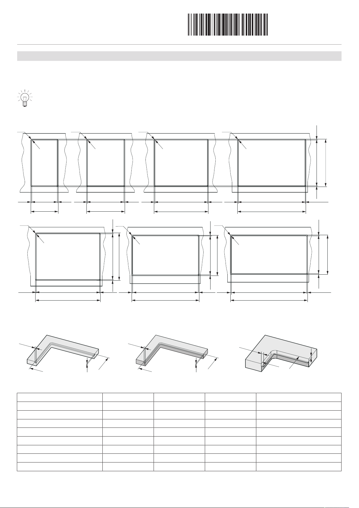
Cut-outs up to the end of 2012 and for Quicklight hobs
Creating the hob mounting
The mounting surface can either be reamed out (Fig.1), or created by installing wood/stone supports (Fig.2) or steel angles (Fig.3).
Reamed out stone panel Execution with wood/stone supports,
Installation dimension H Ra Ri Art. no. angle set
30 8.5 0/+1 14 0–5 H62570
40 8.5 0/+1 14 0–5 H62571
60 8.5 0/+1 14 0–5 H62084
70 8.5 0/+1 14 0–5 H62567
80 8.5 0/+1 14 0–5 H62085
90 8.5 0/+1 14 0–5 H62981
80 Panorama 8.5 0/+1 5 0–5 H62679
90 Panorama 8.5 0/+1 5 0–5 H62568
Execution with steel angle,
bonded or screw mounted
2
bonded or screw mounted
Installation instructions
J004133-R12
Ri
Ra
R
i
Ra
Ri
Ra
Ri
Ra
Ri
Ra
Ri
Ra
8.5
490
507±1
8.5
8.5
680
697±1
8.5
560
577±1
8.5
373
390±1
8.5
270
287±1
8.5
8.5
490
507±1
8.5
8.5
886
903 ±1
8.5
767±1
750
8.5
Installation dimension
80 Panorama
90 Panorama
(as before, see page 2)
0
-1
0
-1
0
-1
0
-1
0
-1
0
-1
0
-1
0
-1
0
-1
0
-1
0
-1
0
-1
Installation
dimension 40
Installation
dimension
30
Installation dimension 60
Installation dimension 70
T
BB B B
Installation dimension 90 Installation dimension 80
T
B B
8.5
8.5
8.5
0
-1
0
-1
0
-1
B
T
T
B
T
H
H
H
Fig. 3Fig. 2Fig. 1
B
For flush installation of a frameless hob
with cement set and sealing strips
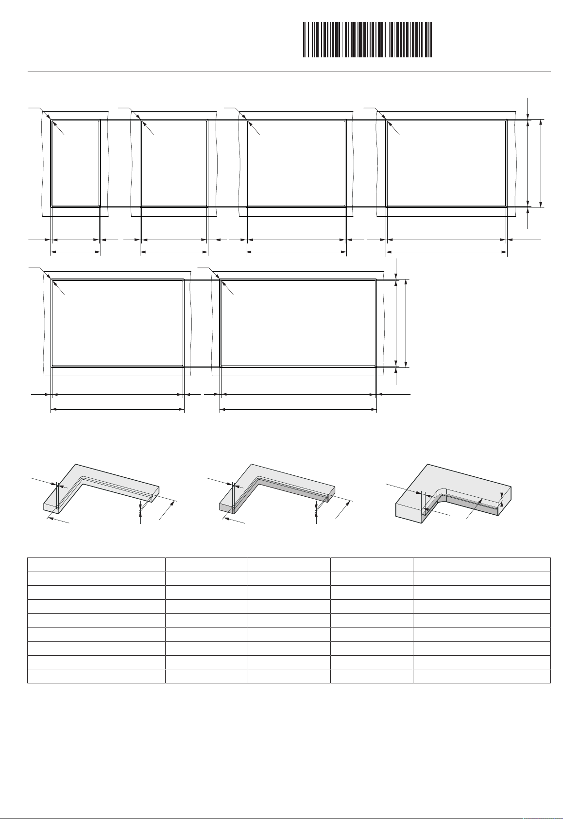
Cut-outs from the beginning of 2013 for Toptronic, induction and gas hobs
J004133-R12
12/06/2018
Creating the hob mounting
The mounting surface can either be reamed out (Fig.1), or created by installing wood/stone supports (Fig.2) or steel angles (Fig.3).
Installation dimension H Ra Ri Art. no. angle set
30 8.5 0/+1 5 0–5 H63770
40 8.5 0/+1 5 0–5 H63771
60 8.5 0/+1 5 0–5 H63772
70 8.5 0/+1 5 0–5 H63773
80 8.5 0/+1 5 0–5 H63774
90 8.5 0/+1 5 0–5 H63775
80 Panorama 8.5 0/+1 5 0–5 H62679
90 Panorama 8.5 0/+1 5 0–5 H62568
Reamed out stone panel Execution with wood/stone supports,
bonded or screw mounted
Execution with steel angle,
bonded or screw mounted
3

Installation instructions
J004133-R12
~60
~60
Fig. 5 Fig. 6Fig. 4
~40
~40
~40
~40
~40
~6
Spacer gauge
Adhesive
Adhesive
Fig. 7
Apply primer to
this area
B × T
B × T
For flush installation of a frameless hob
with cement set and sealing strips
J004133-R12
12/06/2018
Steel angle set
When using the steel angle set, the cut-out B × T and the corner radius can be cut smoothly over the entire worktop thickness. The correct position of the sides of the angle mounting with reference to the work surface is set with the two spacer gauges supplied.
The steel angles can be screw mounted with wood surfaces.
1. Thoroughly clean and degrease the cut surface of the stone with isopropyl alcohol.
2. Coat the bonding surfaces on the stone side sparingly with instant adhesive (Fig. 4).
3. Thoroughly clean and degrease the bonding surface of the steel angle with isopropyl alcohol.
4. Place the two spacer gauges on the first mounting angle (Fig. 4).
5. Place the spacer gauges on the work surface, position the mounting angle centrally on the cut edge of the stone (Fig. 6) and apply
pressure (Fig. 5). The adhesive is sufficiently hardened after approx. 5 minutes and both spacer gauges can be removed. Keep the
spacer gauges for future use.
6. Bond the other three mounting angles using the same procedure.
The instant adhesive requires a curing time (waiting time) of at least 1hour to achieve the final strength and elasticity.
Preparing the cut-out
Lack of care in the preliminary work can result in the ingress of liquid which will lead to the swelling of the wood,
damaging the work surface.
In the case of special work surface materials, the use of unsuitable pre-treatment and adhesive materials can sometimes cause colour changes along the bonding and sealing joint.
▪ Make sure the cut-out is clean, free of dust and any other dirt.
4

Installation instructions
J004133-R12
287–697 mm 767–903 mm
8× 10×
Sealing strip
8 × 5 mm
Spacer
Spacer
~5 cm
~5 cm
Fig. 8
For flush installation of a frameless hob
with cement set and sealing strips
J004133-R12
12/06/2018
Installation and cementing-in
1. Clean any grease or dirt from the edges of the hob with isopropyl alcohol. Leave to dry for a short time. Do not use water with
washing-up liquid!
2. Carefully place the hob in the prepared cut-out and with the help of the spacer set ensure that it sits flush with the surface of the
worktop.
3. Remove the hob. Position the spacer plates and fix them with adhesive tape.
4. Stick the self-adhesive sealing strip (8 × 5mm) supplied with the hob to the cleaned edge mounting surface between the spacer
plates (Fig.8).
As appropriate, the edges of the cut-out and the hob can be covered with wide masking tape before commencing the
cementing-in work, so that only the sealing gap is exposed.
5. Carefully place the hob in the prepared cut-out and with the help of the fugenboy (silicone finishing tool) align it so that the sealing
joint is uniform all around.
6. Check both axes are horizontal using a spirit level.
7. Press the silicone adhesive into the sealing joint, avoiding air bubbles and drawing a somewhat raised bead.
8. Spray the silicone bead with smoothing agent.
9. Using the fugenboy (silicone finishing tool), which has also been sprayed with smoothing agent, spread the silicone bead so it is
flush. Keep cleaning the fugenboy and spraying it and the silicone joint with smoothing agent.
Do not press against the edge of the hob with any tools!
The silicone adhesive requires a curing time (waiting time) of at least 24 hours to achieve the final strength and
elasticity. During this time the hob is not to be placed in operation nor subjected to any form of mechanical stress.
For this reason (impermissible mechanical stress), the final cleaning of the hob is only to take place after the expiry
of this waiting time. Cover the hob with cardboard or similar to prevent dust and dirt from settling during the drying
phase.
5
 Loading...