

Page 1
Installation instructions
1030057-R05
Range hood
Operating mode: Extraction/recirculation
DSMS
The appliance should be installed by qualified personnel only.
Each step must be carried out and checked in full in the order specified.
Validity
These installation instructions apply to:
64005 (DSMS, construction width 11 cm)
General notes
If other firing systems are being used at the same time (e.g. wood, gas, oil or coal fired heating appliances), safe operation is only possible providing a room negative pressure of 4 Pa (0.04 mbar) is not exceeded at the location of the
appliance.
Risk of toxic fumes! An adequate flow of fresh air must be guaranteed e.g. via non-closable openings in doors or
windows and in combination with an air-intake/exhaust-air wall box or by other technical means.
The range hood may only be operated with a gas fired appliance of V-ZUG gas hob type: GAS321GKBZ,
GAS321EKBZ, GAS421GSAZ, GAS421GSBZ, GAS641GKAZ, GAS641EKAZ, GAS641GSAZ, GAS641GSBZ, observing
the permitted combination installation variants. The content of the operating and installation instructions for the listed gas hob must be observed! If operating a permitted gas appliance, the hob hood must be fitted with the dedicated
gas deflector 1031218 (accessory)! Operating a gas appliance without a gas deflector is not permitted!
Failure to observe the above instruction can cause lasting bodily harm and lasting damage to property and the appliance. In
such a case, any and all liability, guarantee and goodwill claims will be rejected in future!
1030057-R05
22/08/2019
The gas deflector may reduce the extraction power of the hob. Select a higher power level if required.
Efficient repairs can only be guaranteed if it is possible to de-install the complete appliance at any time without causing any damage.
Identification plate
▸ The identification plate is located in the base unit on the side panel of the fan motor.
▸ A second identification plate is included in the scope of delivery and should be retained for the purpose of appliance identification.
1
Page 2
Installation instructions
1030057-R05
S1 (12×)
M
U (2×)
E
S2 (4×)
W (4×)
A
T
F
G
Y
Y
N
L
T
V (2×)
R
K
Range hood
Operating mode: Extraction/recirculation
DSMS
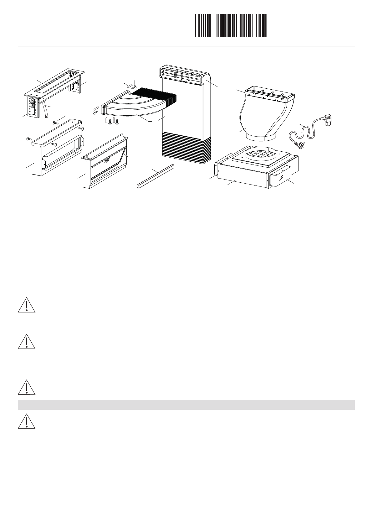
Scope of delivery
1030057-R05
22/08/2019
A Drip tray frame N Mains cable length 1.8m
E Control unit Q Flat channel system
F Metal grease filter R Frame
G Appliance housing T Exhaust air duct
K Control cable U Spacer profile
L Ventilation outlet V Connecting elements
M Fan motor W Plastic covers
Y Mounting angle (surface-mounted installation)
Extraction mode
The extracted air must not be fed into a chimney which is used for exhausting fumes from appliances burning gas or
other fuels.
Observe the local fire regulations.
Recirculation mode
Dedicated accessories that need to be fitted to operate the appliance in the recirculation mode: 1012161 recirculation
box with activated charcoal filters!
▪ Install the recirculation box with activated charcoal filter in the base or adjacent cabinet.
▪ If the recirculation box is not equipped with activated charcoal filters, these have to be ordered and installed before using the appli-
ance for the first time.
The ventilation outlet must not be covered during operation.
Electrical connections
Electrical connections must be carried out by qualified personnel in accordance with the guidelines and standards
for low-voltage installations and the specifications of the local electricity supply companies.
A plug-in appliance may only be connected to a socket outlet with earthing contact, installed according to specifications. An
all-pole mains isolating device with 3 mm contact opening should be provided in the house wiring system. Switches, plug and
socket devices, circuit breakers and fusible cut-outs which are accessible after installation and which have all-poles switching
are permissible as isolating devices. Effective earthing and separately installed neutral and earth conductors ensure safe and
fault-free operation. After installation, live parts and cables with basic insulation must not be accessible. Check old installations.
2
Page 3
Installation instructions
1030057-R05
1
5
2
4
3
3
900–1050
≥105
220
(150)
174*
390–590
268
30–70
258
105
370
548–698
A
479–629
C
B
501
468
523
386
370
185
185
50
110
233
77
300
M
E
T
L
145
16
118
266
ø190
52
102
8
6
370
3
70
217
86
30
50
Y
13
65,5
Range hood
Operating mode: Extraction/recirculation
DSMS
▸ The appliance is designed for use up to a max. altitude of 2000 m above sea level.
▸ Refer to the identification plate for information on the required mains voltage, current type and fuse protection.
The mains plug must not be cut off.
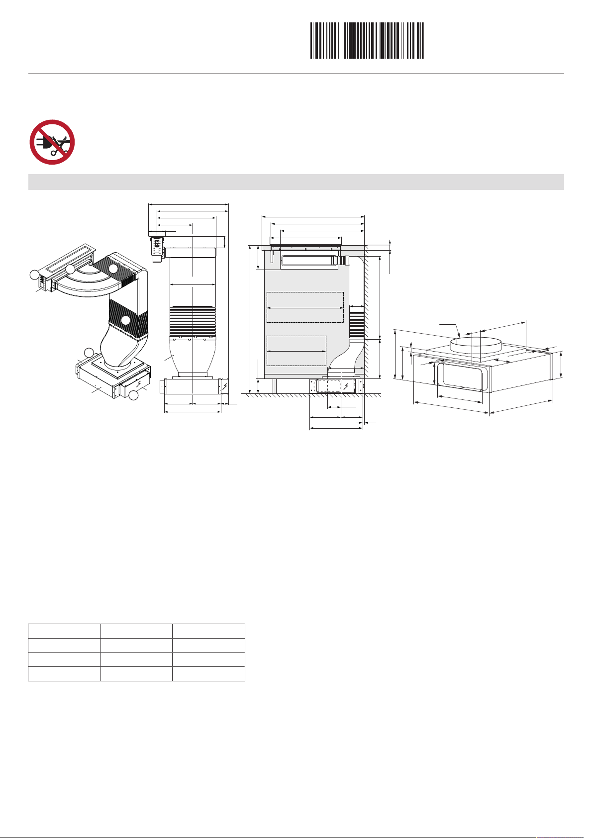
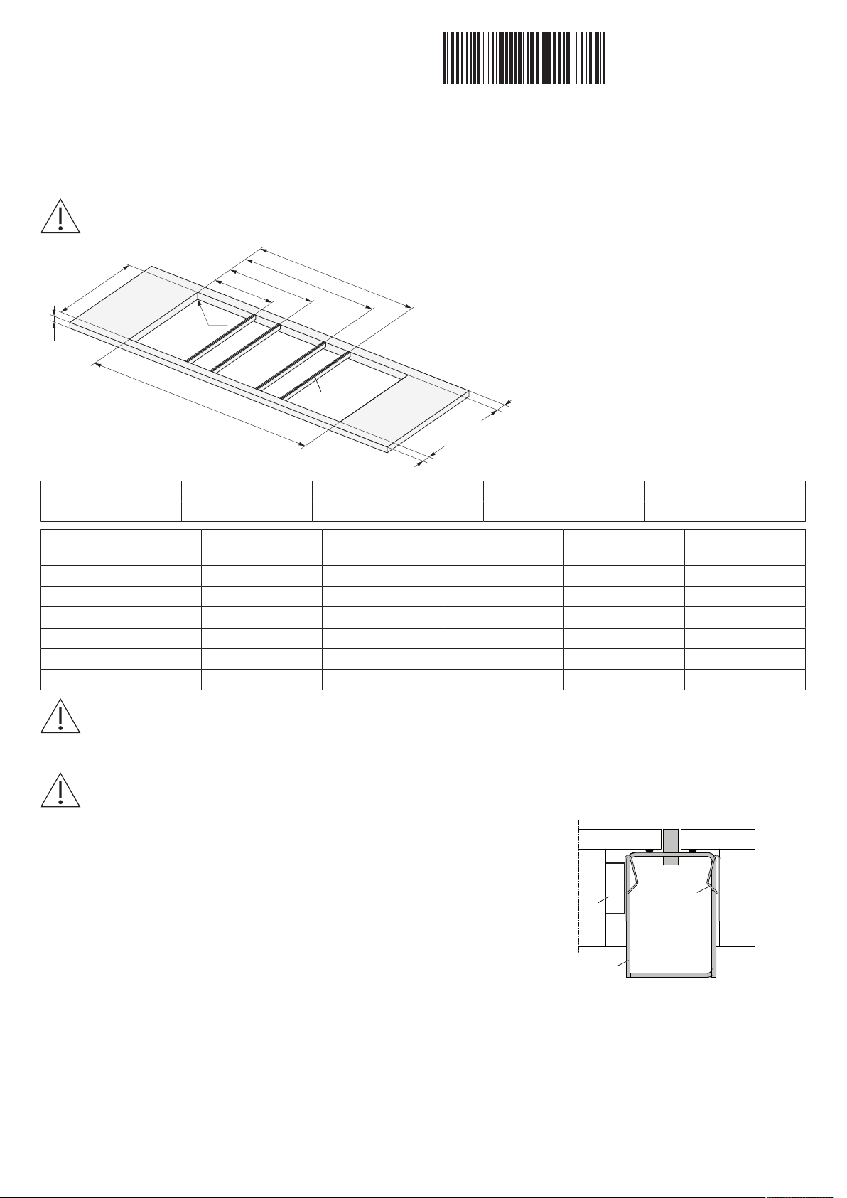
Dimensions
1030057-R05
22/08/2019
1 The connection between the hob hood and the exhaust air duct T can be to the left or right.
2 The ventilation outlet L can be fed through one of the four sides, however this can change the installation type. Standard ventil-
ation outlet L is by means of flat channel or ø150 mm pipe.
3 Depending on space requirements, the position of the fan motor M can be adjusted by shortening the exhaust air duct T.
4 The control unit E can be positioned in the base if required.
5 Mounting angle Y is to be removed for flush installation (gives better accessibility to control unit).
Plan a removable base plate or service flap for fan motor T and recirculation box (for the recirculation mode).
▪
For the recirculation mode, ensure sufficient ventilation so that moisture can escape. Plan in suitable material/wood.
▪
Ensure that the material is sufficiently stable.
▪
All plastering, plasterboarding, wall papering or painting work is to be carried out prior to installing the appliance.
▪
* Flush installation. Surface-mounted installation: 170 mm.
A B C
≥600mm ≥400mm ≥300mm
≥700mm ≥500mm ≥400mm
≥900mm ≥500mm ≤400/500mm
3
Page 4
Installation instructions
1030057-R05
Silicone joints
Spacer plates
Detail Z
Steel angle mounted
with adhesive or screws
8.5
+1
0
8.5
0
-1
8.5
+1
0
8
.5
0
-1
8.5
0
-0.5
8.5
+1
0
G
3
G2
G1
G4
C
E
I
J
F
A
D
Z
K
C
4
90
R0–5
Ra
Y
Detail Y
Range hood
1030057-R05
22/08/2019
Operating mode: Extraction/recirculation
DSMS
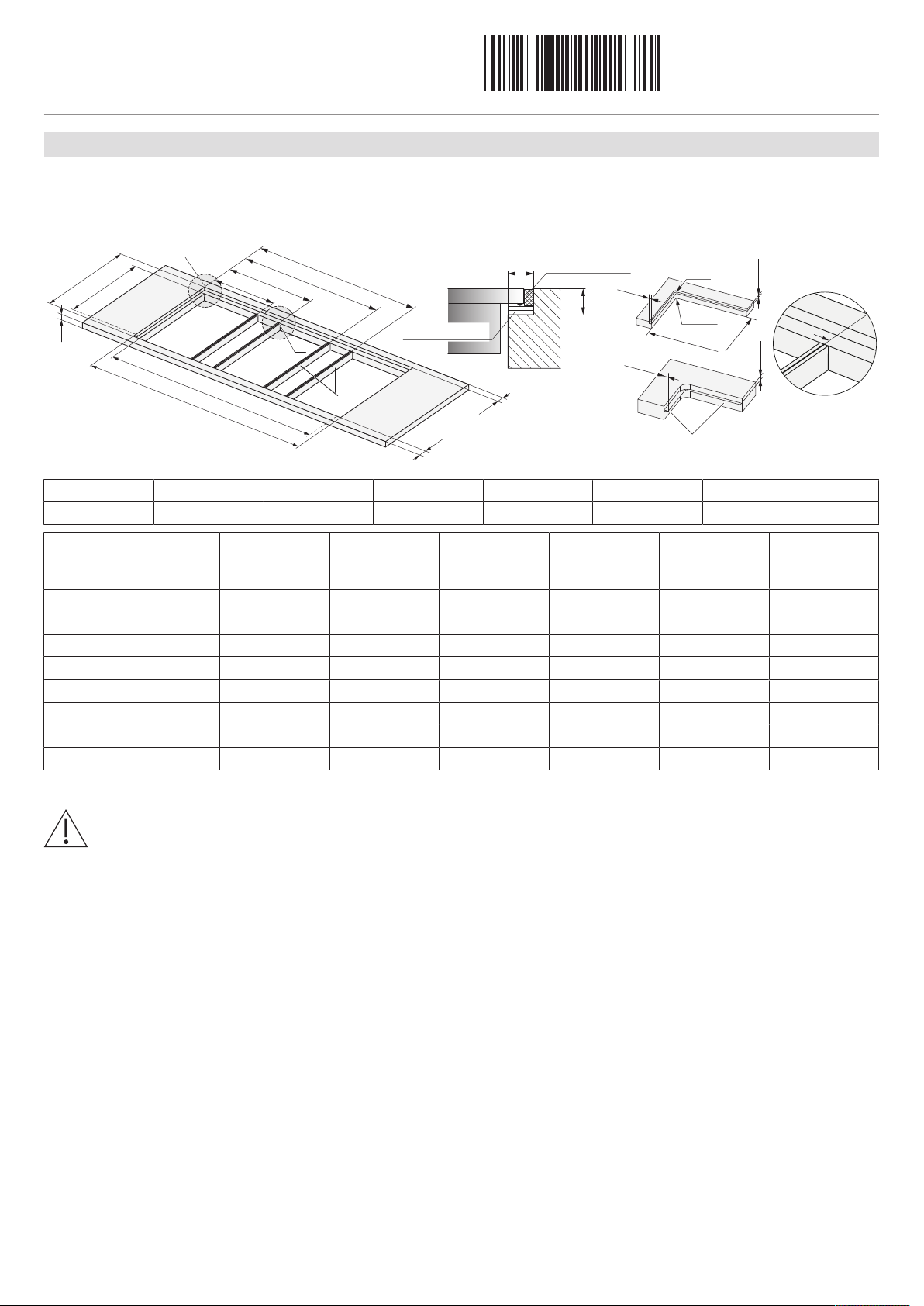
Combination installation
Flush installation
Flush-mounted installation with additional intermediate supports K requires the accessory intermediate support set H63789 (contains
two intermediate supports). Flush-mounted combination installation is described in document 1014381.
A F D I J Ra K
≥30mm 507±1mm 490±1mm ≥41.5mm ≥41.5mm 5mm Intermediate support
Combinations Cut-out width E Cut-out width C Intermediate
support posi-
tion G1
Intermediate
support posi-
tion G2
Intermediate
support posi-
tion G3
Intermediate
support posi-
tion G4
30+11+30cm 684mm 667mm 285.5mm 398.5mm - 30+11+40cm 787mm 770mm 285.5mm 398.5mm - 40+11+40cm 890mm 873mm 388.5mm 501.5mm - 11+80+11cm 993mm 976mm 114.5mm 878.5mm - 40+11+40+11+40cm 1390mm 1373mm 388.5mm 501.5mm 888.5mm 1001.5mm
40+11+60+11+40cm 1577mm 1560mm 388.5mm 501.5mm 1075.5mm 1188.5mm
40+11+70+11+40cm 1697mm 1680mm 388.5mm 501.5mm 1195.5mm 1308.5mm
40+11+80+11+40cm 1767mm 1750mm 388.5mm 501.5mm 1265.5mm 1378.5mm
Installation
Establish the mains supply connection before inserting the appliance.
▸ Create an accurate installation cut-out.
– The mounting surface can be reamed out or created by installing wood/stone supports or using the steel angle set (accessory
available for order).
▸ Prepare the mounting cut-out and appliance according to the specifications in the cementing-in instructions J004130 and align the
appliance in the mounting cut-out.
▸ Carefully cement the appliance in place and leave the silicone sealant to dry for at least 24 hours.
4
Page 5
Installation instructions
1030057-R05
G3
G2
I
J
C
D
A
Ra
G1
G4
K
N
K
U
Range hood
Operating mode: Extraction/recirculation
DSMS
1030057-R05
22/08/2019
Surface-mounted installation
Surface-mounted installation requires the accessory side strip set 1028587 and either the intermediate support K 1019199 (black) or
1014361 (stainless steel). Articles are available for order as accessories. Surface-mounted combination installation is described in doc-
ument 1013773.
A WOK glass ceramic hob cannot be surface mounted!
A D I J Ra
≥30mm 490±1mm ≥50mm ≥50mm 0–5mm
Combinations Cut-out width C Intermediate sup-
port position G1
30+11+30cm 667mm 277mm 390mm - 30+11+40cm 770mm 277mm 390mm - 40+11+40cm 873mm 380mm 493mm - 40+11+40+11+40cm 1373mm 380mm 493mm 880mm 993mm
40+11+60+11+40cm 1560mm 380mm 493mm 1067mm 1180mm
40+11+70+11+40cm 1680mm 380mm 493mm 1187mm 1300mm
Do not damage the sealing bead. The sealing bead must lie all around the edge of worktop.
Intermediate sup-
port position G2
Intermediate sup-
port position G3
Intermediate sup-
port position G4
Installation
Establish the mains supply connection before inserting the appliance!
▸ Create an accurate installation cut-out.
▸ Carefully put the appliance in the installation cut-out and press against the worktop with
sufficient overlap.
▸ Readjust the hobs if necessary so that all the front edges form a line and the centring
element N snaps into the cut-out on the intermediate support K. Check this by looking at
the spacer profile U of the intermediate support K from below and ensuring the centring
elements project into the opening provided.
5
Page 6

Installation instructions
1030057-R05
258
105
900–1050
≥105
220 (150)
13
174*
390–590
268
30–70
370
548–698
≥600
479–629
≤300
≤400
501
65.5
900–1050
≥105
174*
390–590
268
30–70
258
105
548–698
≥700
479–629
≤400
≤500
501
220 (150)
13
370
65.5
900–1050
≥105
174*
390–590
2
68
30–70
258
105
370
≥900
≤500
501
548–698 201
220 (150)
65.5
370
271
220(150)
65.5
Range hood
Operating mode: Extraction/recirculation
DSMS
1030057-R05
22/08/2019
Installation overview base unit
Wall installation with depth of ≥600 mm Wall/island installation with depth of ≥700 mm
Island installation with depth of ≥900 mm Variant with rotated fan motor
* Flush installation. Surface-mounted installation: 170 mm.
6
Page 7

Installation instructions
1030057-R05
S1
S3
G
R
Y
Y*
Y*
(*)
F
A
S1
S1
U
SL
Range hood
Operating mode: Extraction/recirculation
DSMS
Installation
Before installation determine whether the exhaust air duct should be to the left or right.
▸ (* ) For flush installation only: Remove mounting angle Y by
unscrewing the 4 screws S3.
▸ All installation types: Fasten frame R to housing G with 4
screws S1.
1030057-R05
22/08/2019
▸ Insert metal grease filter F from the side into collection tray A.
▸ Insert collection tray A from above into the hob hood.
Necessary only for surface-mounted installation:
▸ Attach spacer profile U (supplied) to side with 8 screws S1, then
attach side strips SL (accessory 1028587) with 8 screws S1.
7
Page 8

Installation instructions
1030057-R05
K
99
118
8.5
8.5
507
490
R5
S1
700
600
320
320
320
320
Range hood
Operating mode: Extraction/recirculation
DSMS
For flush installation: Prepare the cut-out according to cementing-in instructions J004130.
▸ Place the hob hood into the prepared cut-out from the top and
onto the intermediate supports K and align.
▸ Optional for surface-mounted installation: Secure hob hood
from below with 2 screws S1 (assembled ex-factory), tightening
to a torque of ≤5 Nm.
1030057-R05
22/08/2019
▸ Prepare base according to intended installation variant. Ex-
amples:
8
Page 9

Installation instructions
1030057-R05
≥105
M
U
U
E
M
L
Range hood
Operating mode: Extraction/recirculation
DSMS
▸ Position fan motor M in base according to installation type.
▸ For recirculation mode: Prepare connection for recirculation
box with activated charcoal filters.
▸ Plan in enough space and ensure access to the recirculation
box for replacing the activated charcoal filters!
Installation type: Extraction or recirculation mode. Observe recirculation box U and flat channel system options (accessory available for order).
▸ The individual components required must be taken into account
during planning!
1030057-R05
22/08/2019
▸ Where space is limited, the ventilation outlet L can be reposi-
tioned. To this end, fan motor M is rotated (see view above) or
converted (see view below). Feed the ventilation outlet L
through one of the four sides. The ventilation outlet L and control unit E can be switched if required.
9
Page 10

Installation instructions
1030057-R05
K
E
E*
E*
T
S2 (4×)
W (4×)
Range hood
Operating mode: Extraction/recirculation
DSMS
Make sure there is enough space for the ventilation outlet!
▸ Connect control cable K on the underside of the hob hood to
the control unit E.
▸ Control unit E can be optionally* positioned away from the mo-
tor housing on a nearby wall or in the base.
▸ Cut the exhaust ducting components T to size according to in-
stallation type and assemble using connecting elements V.
1030057-R05
22/08/2019
▸ Insert exhaust ducting T into motor housing.
▸ Fasten exhaust ducting T to hob hood with 4 screws S2. Attach
the plastic covers W from the inside to screws S2.
10
Page 11

Installation instructions
1030057-R05
N
Range hood
Operating mode: Extraction/recirculation
DSMS
▸ All connection components must be cleaned and then com-
pletely sealed using suitable sealing tape or accessory H42067.
▸ Connect the appliance to the power supply using the mains
cable N.
▸ Follow the operating instructions for using the appliance for the
first time.
1030057-R05
22/08/2019
Before installing the hobs and completing the installation: Carry out function check!
Check the hob hood and exhaust ducting for tightness and noise.
11
Page 12

Installation instructions
1030057-R05
B
B
B
B
A
1
3
2
Range hood
Operating mode: Extraction/recirculation
DSMS
For use with a gas appliance
The hob hood may only be used with the dedicated gas deflector 1031218 (accessory) with one of the gas appliances
listed below. Operating the hob hood without the gas deflector is not permitted!
Permitted gas appliances for use with the hob hood:
V-ZUG gas hob type: GAS321x, GAS421x, GAS641x, observing the permitted combination installation variants.
Combining the hob hood with two gas hobs is not permitted!
Using another gas appliance type/model or manufacturer is not permitted and can cause lasting damage to the hob
hood.
Failure to observe the above instruction can cause lasting bodily harm and lasting damage to property and the appliance. In
such a case, any and all liability, guarantee and goodwill claims will be rejected, now and in the future!
Burns hazard!
The appliance and surrounding components get hot during operation! Allow the fan flap, gas deflector and other components
to cool down before touching them.
1030057-R05
22/08/2019
Fire hazard!
Grease deposits can build up in the grease filter and catch fire. Clean the grease filter regularly. Only operate the appliance
with the gas deflector.
Permitted installation variants (V-ZUG gas hob only)
As a variant may also be installed on either side of the appliance.
A Caution: Hot surface!
B Gas deflector correctly mounted.
The gas deflector 1031218 (required accessory) reduces the
deflection/disturbance of the gas flame at the burner and prevents it being extinguished by a draft.
▸ Open fan flap 1.
▸ Set the gas deflector 2 in the correct position relative to the
gas appliance.
▸ Switch on hob hood 3.
12
Page 13

Installation instructions
1030057-R05
L
F
Range hood
Operating mode: Extraction/recirculation
DSMS
Extraction mode
There is a danger of toxic fumes developing if the range hood is operated at the same time as an ambient air-dependent firing system!
The conversion kits and suitable flat channel systems are available for order as accessories.
▸ Fasten and seal flat channel F to ventilation outlet L.
1030057-R05
22/08/2019
▪ Only use pipes with a smooth inner surface or flexible duct hoses made from non-flammable materials for exhaust ductwork.
▪ To achieve the greatest possible air extraction with the lowest noise levels, please observe the following:
– Standard ventilation outlet is by means of flat channel or pipe.
– The diameter of the exhaust duct pipe must not be less than ø150mm.
– The exhaust ducting should be as short and straight as possible.
– Only use connection elbows with large radii.
– The exhaust ducting must not be kinked or compressed.
– Make sure that all connections are secure and airtight.
Any constriction of the airflow will reduce extraction performance and increase operating noise.
▪ If the exhaust duct is to be routed outdoors, we recommend in-
stalling a telescopic wall box (accessory available for order).
▪ If the exhaust air is to be ducted into a chimney flue, the intake
piece must be aligned with the flow direction of the flue.
▪ If the exhaust duct runs through cool rooms, lofts, etc., there may be sharp variations in temperature in individual areas. Vapour and
condensation is to be expected. This makes it therefore necessary to insulate the exhaust ducting / air duct.
13
Page 14

Installation instructions
1030057-R05
U
L
3
5
222
600
515
305
100
10
9
90
35
Range hood
Operating mode: Extraction/recirculation
DSMS
1030057-R05
22/08/2019
Recirculation mode
Conversion kits and suitable flat channel systems are available for order as accessories.
For recirculation mode with recirculation box, ensure access for maintenance purposes and also ensure the blow-out opening is at least
500 cm² (e.g. base recess or lamella base).
If an exhaust air connection is not structurally possible, the range hood must be set up for recirculation operation. There is the following possibility to do this:
Recirculation mode with recirculation box
▸ Connect the recirculation box U to the ventilation outlet L.
The activated charcoal filters are integrated in the recirculation box
1012161. Activated charcoal filters are not used in the range hood.
For accessories, see the planning aid.
14
 Loading...