

Vulcan-Hart VFBMW Service Manual
SERVICE MANUAL
MODEL VFBMW
ELECTRIC
FLASH
BA KE
®
/ MICROWAVE
OVEN
ML 126807
- NOTICE This Manual is prepared for th e use of trained Vulcan Service
Technicians and should not be used by those not properly
qu alif ied. If yo u have attend ed a Vulcan Service School for this
product, you may be qualified to perform all the procedures
described in this man ual.
Thi s manu al i s no t i nten ded to be al l en comp assi ng . I f you have
not attende d a Vulcan S ervic e School for this produ ct , you should
read, in its entirety, the repair procedure you wish to perform to
determine if you have the necessary tools, instruments and skills
required to perform the procedure. Procedures for which you do
not have th e n ecessary too ls, in strument s and skills should be
performed b y a trained Vu lcan Service Technician .
Reproduction or other use of this Manual, without the express
written consent of Vulcan-Hart, is prohibited.
A product of VULCAN-HART LOUISVILLE , KY 40201-0696
Form 24694 ( A pr il 2001)

FLASHBAKE® / MICROWAVE O VEN
TABLE OF CONTENTS
RADIATION SAFETY I NS TRUCTIONS ....................................................... 4
GENERAL............................................................................. 4
Introduction ........................................................................ 4
Electrical Specifications............................................................... 5
Installation......................................................................... 5
Operation.......................................................................... 6
Cleaning .......................................................................... 6
Tools ............................................................................. 6
REMOVAL AND REPLACEMENT OF PARTS ................................................. 7
Covers and Panels ................................................................... 7
Main Cover..................................................................... 7
Back Panel ..................................................................... 8
Bottom P anel ................................................................... 8
Front Vent Grill ..................................................................... 8
Power Cord ........................................................................ 9
Vent Fan Capaci tor .................................................................. 9
Vent Fan .......................................................................... 9
Cavity Lamp and Damper Door Assembly ................................................ 10
Damper Housing Thermal Fuse ........................................................ 10
Fuse - 20 AMP..................................................................... 11
Door............................................................................. 12
Control Panel Assembly .............................................................. 12
Control Panel .................................................................. 12
Control Board.................................................................. 13
Keypad Assembly ............................................................... 14
Display....................................................................... 14
LED Display ................................................................... 14
Relay Board....................................................................... 14
Door Switch Assembly ............................................................... 15
Upper Lamp Housing and Duct Assembly ................................................ 16
Upper Lamp Assembly ............................................................... 18
Upper Lamp Fan ................................................................... 19
Upper Lamp Housing Ducts ........................................................... 19
Right Duct .................................................................... 19
Left Duct ..................................................................... 20
Cavity Thermistor .................................................................. 20
High Volt age Transformer ............................................................ 20
Magnetron ........................................................................ 21
Magnetron Cooling Fan .............................................................. 22
Lower Lamp Housing and Duct Assembly ................................................ 23
Lower Lamp Fan ................................................................... 23
Turntable Motor .................................................................... 24
Thermal Cut Outs .................................................................. 24
Cavity, Top Left ................................................................ 24
Upper Lamps .................................................................. 25
Lower Lamp ................................................................... 26
Magnetron .................................................................... 26
Capacitor ( High Voltage) ............................................................. 26
Diode............................................................................ 27
Low Voltage Transformer ............................................................. 27
Choke Filter....................................................................... 27
Noise Filter Board .................................................................. 28
SERVICE PROCEDURES AND ADJUSTMENTS .............................................. 29
Door Latching Adjustment ............................................................ 29
Thermistor Test .................................................................... 29
Form 24694 ( A pr il 2001) Page 2 of 52

FLASHBAKE® / MICROWAVE O VEN
Door Switches - Adjustment........................................................... 29
Testing Com ponents ................................................................ 30
Transformer - High Voltage ....................................................... 30
Capacitor - High Voltage ......................................................... 30
Diode ........................................................................ 30
Low-Voltage Transformer ......................................................... 30
Keypad....................................................................... 30
Primary Interlock ............................................................... 31
Door Sensing (Secondary Interlock) ................................................. 31
Door Interlock System ........................................................... 31
Performance Test for Microwave ....................................................... 32
Performance Test for Halogen Lam ps ................................................... 32
Radiation Leak age Test .............................................................. 32
ELECTRICAL OPERATION .............................................................. 33
Component Func tion ................................................................ 33
Component Locat ion ................................................................ 34
TCO Locations, Switch Locations................................................... 35
Control Board Layout................................................................ 36
Control Board Connec tor Identificat ion ............................................... 36
Air Flow Diagrams .................................................................. 37
Combi Cook ................................................................... 37
Magnetron .................................................................... 38
Microwave .................................................................... 38
Component Wiring Diagram s .......................................................... 39
Thermal Cut Outs............................................................... 39
Door Switches ................................................................. 40
Halogen Lamps ................................................................ 41
Schematic Diagram ................................................................. 42
Wiring Diagram .................................................................... 44
Sequence of O per ation .............................................................. 46
TROUBLESHOOTING .................................................................. 47
Diagnosing Non Operating Unit ........................................................ 47
Fault Codes ....................................................................... 48
Troubleshooting Flow Chart ........................................................... 50
CONDENSED SPARE PARTS LIST ........................................................ 51
© VULCAN 2001
Form 24694 ( A pr il 2001)Page 3 of 52
FLASHBAKE® / MICROWAVE O VEN GENERAL
RADIATION SAFETY INSTRUCTIONS
PRECAUTIONS TO BE OBSERVED BEFORE
AND DURING SERVICING TO AVOID P OSSIBLE
EXPOSURE TO EXCESSIVE MICROWAVE
ENERGY.
1. Do not operate or allow the ov en to be
operated with the door open.
2. Make the f ollowing safety checks on all ovens
to be serviced before activating the magnetron
or other microwave source, and make repai r s
as necessary:
A. Interloc k operation.
B. Proper door cl osi ng.
C. Seal and sealing surfaces (arcing, wear,
and other damage).
D. Damage to or loosening of hinges and
latches.
E. Evidence of dropping or abuse.
GENERAL
INTRODUCTION
General
The combination FlashBake
cooks the outside of foods muc h like conventional
radiant heat, while also penetrating the surf ac e so
the inside cook s simultaneously. While halogen light
is the primary source of power, a “microwave boost”
is added with certain foods. Foods cook evenly and
fast, retaining their natural moisture.
®
and microwave oven
3. Before t ur ning on mi c r owave power for any
servi ce test or inspection within the microwave
generating compartm ents, check the
magnetron, wave guide or t r ansmission line
and cavity f or proper alignment, integrity, and
connections.
4. Any defective or misadj ust ed c omponent in t he
interl ock, monitor, door seal, and microwave
generation or transmission systems shall be
repaired, r eplaced, or adjusted by pr oc edur es
described in t his manual before the oven is
released to the owner.
A microwave leakage ch eck to verify
5.
compliance with the Federal Performance
Standard should be performed on each
oven prior to release to t he owner.
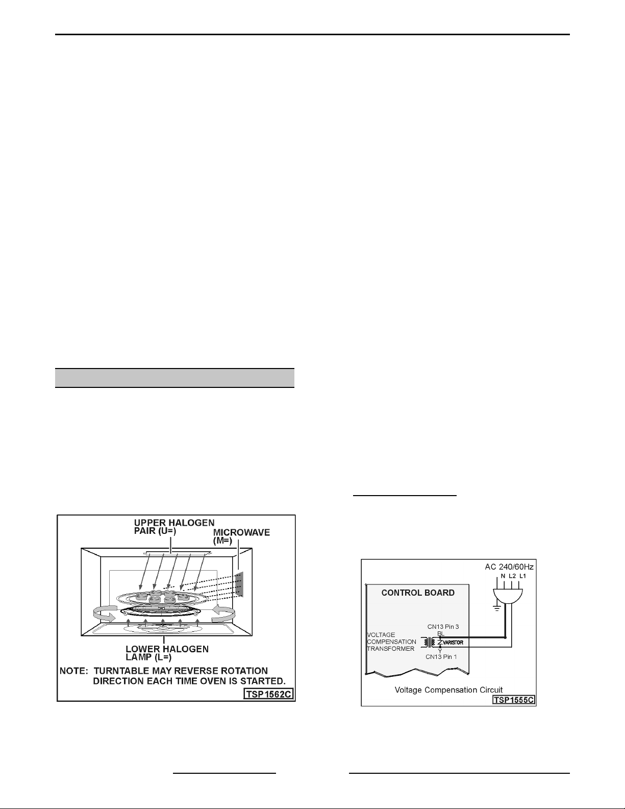
Ov en features:
• Turntable rotates to ensure even cooking.
• Halogen lamps; two 1500 watt lamps cook from
the top and one 1500 watt lamp cooks fr om the
bottom.
• Microwave “boost” is automatical ly added with
certain foods.
• Ov en c an also be used as a 950-watt
microwave oven.
• Voltage Compensation
monit ored by the v oltage compensat ion
transformer on the contr ol board. It monitors
voltage from L2 to neutral at the start of each
menu cook selec tion and adjusts the cooking
tim e to achieve qualit y results.
: Line voltage is
Form 24694 ( A pr il 2001) Page 4 of 52
The optimal line voltage of 120VA C has no
compensation. Above 120V A C , tim e is
subtracted f rom the recipe (up to -30 sec.).
Below 120VAC, time is added to the recipe (up
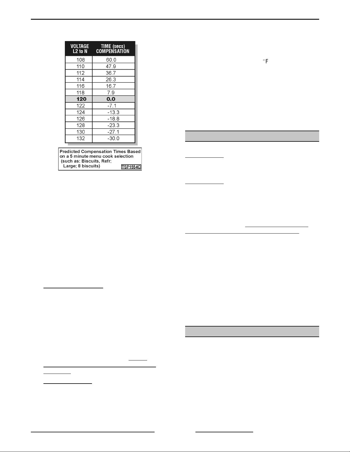
FLASHBAKE® / MICROWAVE O VEN GENERAL
to +60 sec.). Compensation voltage range
is 108 to 132VAC.
Voltage compensation occurs after
approximately 5 seconds of menu cook
operation. The display will show "OPTIMIZING
COOK TIME.” The time will flash and then
display the new adjusted time, based on the
amount of voltage compensation required.
NOTE:
during menu cook operation and only occurs
once during the cooking cycle (at the initial
start of the menu cook cycle). When using
menu cook, y ou are selecting prepr ogr ammed
item s from a menu. These items require
compensation for accurate and consistent
cooking results. When c ook ing with combi
cook, voltage compensation does not occur.
• Thermal Compensation
item s consecut ively, the temperature i nsi de the
oven cavity can become very hot. The control
automatically compensates for the increased
temperat ure by adjusting t he c ook ing power
levels of both the upper and lower halogen
lamps. At the start of each new cook operation
(just pri or to voltage compensation occurring),
the cavity ther mistor reads the c avity
temperat ure and the control boar d adjusts
power levels to compensate for heat that
already ex ists in the oven cavity. It is not
possible to see the
the display.
Voltage compensation only oc c ur s
: When cooking food
adjusted
power levels in
cycle. The consumer will not notice any change
in display r eadout, however, they may notice
that the hal ogen lamps are cycling differently
than expect ed.
In the unlikely event that internal oven cavity
temperat ure exceeds 600(F, combi cook
operation will be terminated. When the control
board terminates the combi cook cycle, it
returns the displ ay to its normal off position
(with ti me of day c lock showing in display ) .
Since the t hermistor in the cavity is constantly
being monitored by the control board, when the
unit cool s, the control board r eturns oven to
normal operation.
ELECTRICAL SPECIFICATIONS
Model FBM W2 i s supplied with a cord and plug.
For cord and plug units, an NEMA 14-30R wall
receptacle is required.
Model FBM W3
NOTE:
the green and white wires crimped together . On
these units the frame i s grounded by c onnec tion of
ground lead to neutral white lead. Effective January
1, 1996, the National Elec trical Code r equires that
new construction use a (4) conductor connection
and will not permit grounding through neutral. If
used in new construction after January 1, 1996, or if
local codes do not per mit grounding through neutral
white lead, open the factory crim p c onnec tion and
connect neutral white lead to br anc h c ircuit neutral
conductor in usual manner.
120/208-240, 60 Hz, single phase, 30 amp power
supply is requir ed.
Wor k ing voltage = 208 to 264V A C.
Early hard wir ed models left the factory with
is a unit intended to be hard wired.
INSTALLATION
Refer to the INSTRUCTI ONS manual shi pped with
the ov en for installation instructi ons.
• Thermal Protection
temperat ures reach somewhere between 500
and 600 degrees, or if cook time exceeds 12
minut es of cooking at halogen power levels
greater than 7, all power levels (lamps and
microwave) will be reduced by the control
board to 7 for the remai nder of the combi cook
: If oven cavity
Form 24694 ( A pr il 2001)Page 5 of 52
FLASHBAKE® / MICROWAVE O VEN GENERAL
OPERATION
Refer to the INSTRUCTI ONS manual shi pped with
the ov en for com plete operati ng instructi ons,
precautions and utensi ls to use.
CAUTION: Do not attempt to cook with the oven
empty. If there is no l oad in the cavity to absorb
the microw ave energy, the energy will be
reflected b ack into the magnetron cau sing it to
overheat which may result in magnetron failure.
NOTE:
and off during a combi cook cycle, sometimes even
at full power levels. This is normal. The oven senses
the heat level and adjusts automati cally. What is
important to note i s t hat while the power levels have
been reduced (thermal com pensation), the power
levels which will show in the display will be the
original power lev els.
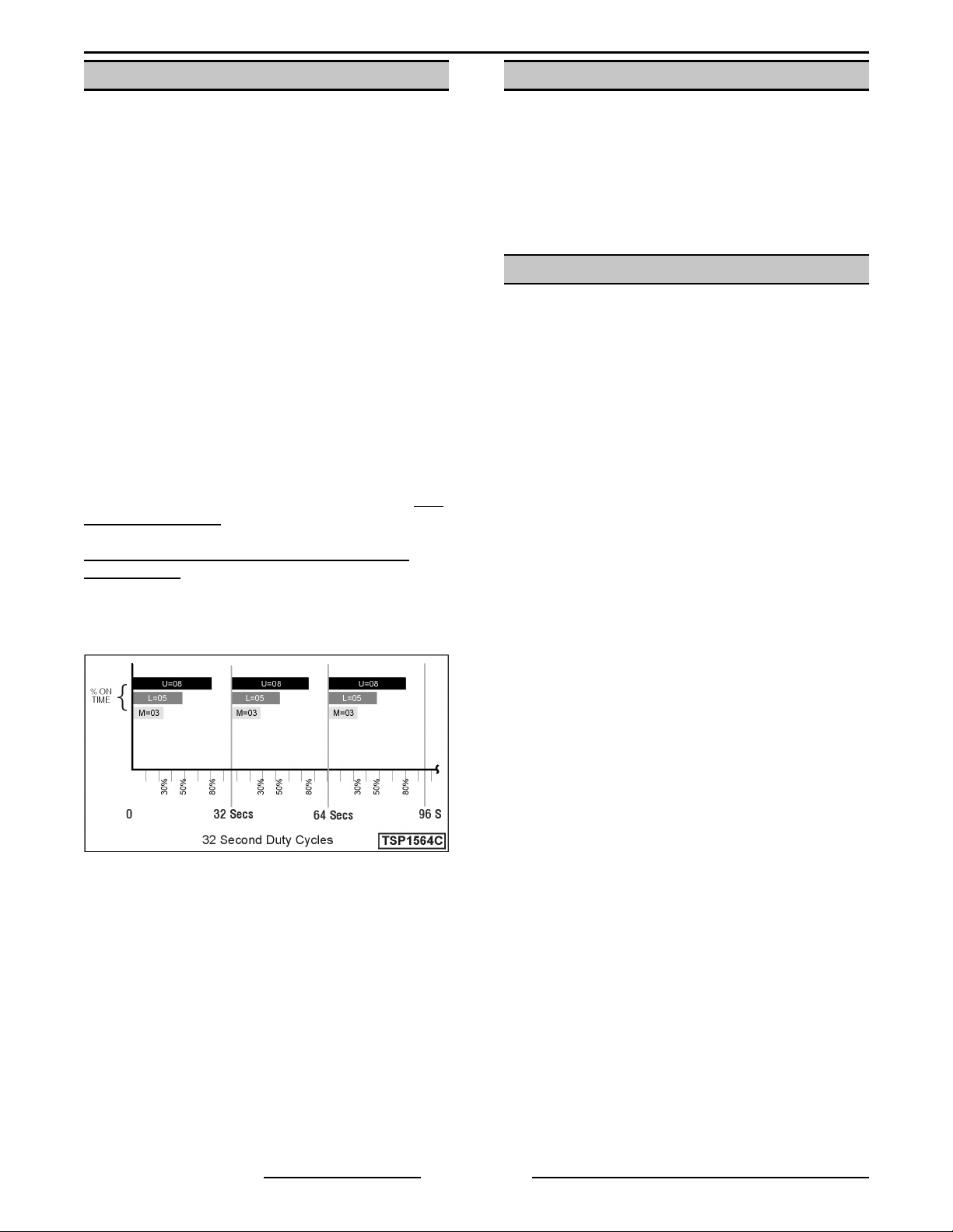
NOTE:
which control s the upper halogen lamps (U=), the
lower halogen lamp (L=), as well as the high
voltage/magnetron circuits (M=), oper ates on a duty
cycle of 32 seconds. This means the power level
you select for each component controls the
percentage of "on" time during each 32 second
period of time.
Example:
(U=08), lower halogen lamp set at 50% (L=05), and
microwave set at 30% (M=03).
The halogen lamps will dim and cycle on
The program ming on the control board
Upper halogen lamp pair set at 80%
CLEANING
CAUTION: Never use oven cleaners t o clean the
oven. Never use abrasives or sharp objects on
the oven walls or window.
Refer to the INSTRUCTI ONS manual shi pped with
the ov en for com plete cleaning instructions.
• Set of standar d hand tools
• Volt-ohm meter wi th a sensitivity of at least
20,000 ohms per volt.
• Field servic e gr ounding kit. ( TL 84919)
• 1 liter beaker (made of material suitable for
high oven temperat ur e)
• Thermometer (519928 or 538454)
• A mic rowave leak detector that has been
calibrated by the manufacture wit hin the year.
Exam ples follow:
1. Holiday: Model HI-1801
2. Simpson: Model 380-2
TOOLS
Model HI-1501
Form 24694 ( A pr il 2001) Page 6 of 52
FLASHBAKE® / MICROWAVE O VEN REMOVAL AND REPLACEMENT OF PARTS
REMOVAL AND REPLACEMENT OF PARTS
NOTE:
NOTE:
routing of wires for proper r einstallat ion.
CAUTION: All removed screws must b e replaced to p revent possib le microwave energy leakage. Mo st of
the screws you will be removing will be of two sizes, 1/2" shank and 3/8" shank Phillips head screws.
Note their positio ns for prop er reinstallation. So me screws have machine t hreads and must be installed
in proper locations.
NOTE:
adjusted, a radiation leak test MUST be performed in the magnetron area.
NOTE:
the appropriate place before connectors can be separated. When installing connec tors, take extra care to ensure
all tabs in gang connectors are properl y aligned bef or e c onnec ting. When installing connectors, listen for click
sound and stop. If connector is seated on too far it may be diffic ult to remove. E xercise caution when removing
connectors so that components are not damaged.
Main Cover
WARNING:
POWER TO T HE MACHINE AT THE MAIN
CIRCUIT BO X. P LA CE A TAG ON THE CI RCUIT
BOX INDICATING THE CIRCUIT IS BEING
SERVICED.
References to left and right are as viewed from the front (operator side) of unit.
Any cable ties removed in order t o service the unit should be replaced. Be sure to note t he location and
During reassembl y , before i nstalling main cover and after all necessary components are replaced and
New type connectors are used on this oven. Some have locking tabs that must be released by pressing i n
COVERS AND PANELS
DISCONNECT THE ELECTRICAL
NOTE:
screws (non remov able without special tool)
installed. If y ou encounter one of t hese units,
remove the special screws and replace them with
standard screws. Also remove the label indicating
the use of the non remov able screws.
Some earl y units had two security type
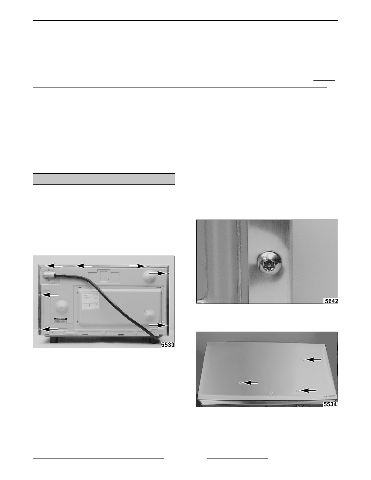
1. Remove screws securing cover at rear of unit.
MODEL FBMW2 SHOWN
2. Remove screws securing top of cover. Note
that these are silver screws.
Form 24694 ( A pr il 2001)Page 7 of 52
FLASHBAKE® / MICROWAVE O VEN REMOVAL AND REPLACEMENT OF PARTS
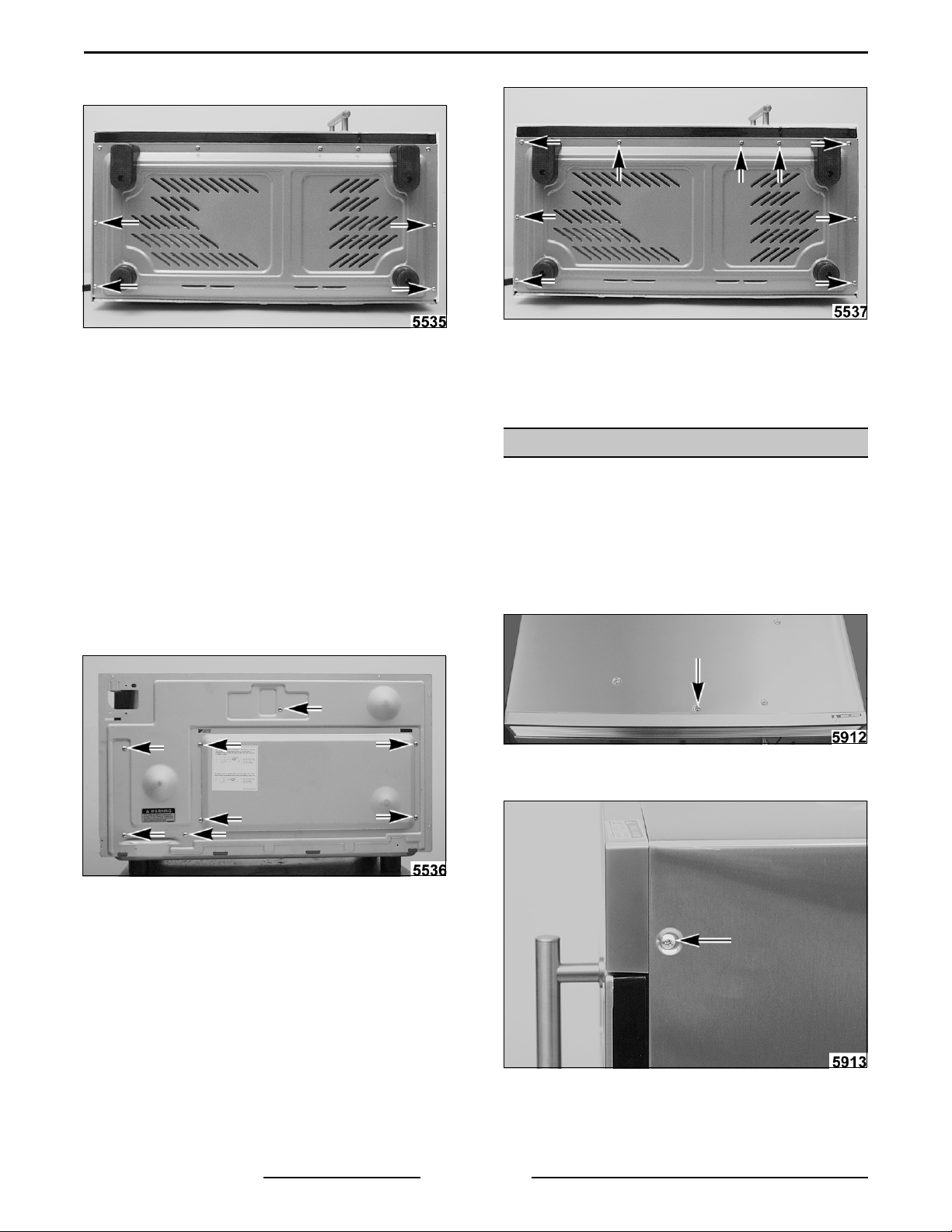
3. Remove two screws securing each side of
cover located underneath si de of unit.
4. Slide cover rear ward to disengage cover from
front si des of unit.
5. Carefully lift cover with vent grill off unit.
6. Reverse proc edur e to install .
Back Panel
1. Remove screws securing bottom panel.
2. Disengage bottom panel from back panel and
remove bottom panel.
3. Reverse proc edur e to install .
FRONT VENT GRILL
WARNING:
POWER TO T HE MACHINE AT THE MAIN
CIRCUIT BO X. P LA CE A TAG ON THE CI RCUIT
BOX INDICATING THE CIRCUIT IS BEING
SERVICED.
1. Remove "MAIN COV E R.”
2. Remove "POWER CORD.”
3. Remove screws securing back panel.
4. Pull bot tom of bac k panel away from unit to
disengage it from bottom panel.
DISCONNECT THE ELECTRICAL
WARNING:
POWER TO T HE MACHINE AT THE MAIN
CIRCUIT BO X. P LA CE A TAG ON THE CI RCUIT
BOX INDICATING THE CIRCUIT IS BEING
SERVICED.
1. Remove screw securing grill on top.
2. Remove one screw on each side of grill.
DISCONNECT THE ELECTRICAL
5. Reverse proc edur e to install .
Bottom panel
WARNING:
POWER TO T HE MACHINE AT THE MAIN
CIRCUIT BO X. P LA CE A TAG ON THE CI RCUIT
BOX INDICATING THE CIRCUIT IS BEING
SERVICED.
Form 24694 ( A pr il 2001) Page 8 of 52
DISCONNECT THE ELECTRICAL
3. Pull grill out front.
4. Reverse proc edur e to install .
FLASHBAKE® / MICROWAVE O VEN REMOVAL AND REPLACEMENT OF PARTS
POWER CORD
BOX INDICATING THE CIRCUIT IS BEING
SERVICED.
WARNING:
1. Remove "MAIN COV E R.”
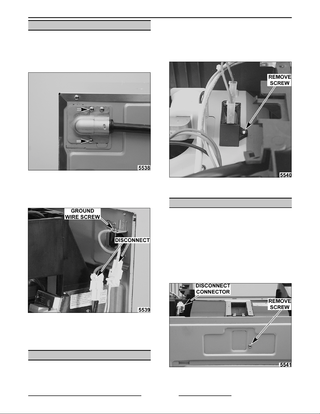
2. Remove two screws securing strain relief plate
and remove plate.
MODEL FBMW2 WITH MAIN COVER INSTALLED
3. Disconnect power cord connectors.
UNPLUG THE MAIN POWER CORD.
1. Remove "MAIN COV E R.”
2. Disconnect wires from capacitor.
3. Remove screw securing capacit or .
4. Reverse proc edur e to install .
4. Remove screw securing ground wire.
NOTE:
5. Remove power cord through hole in back
6. Reverse proc edur e to install .
Screw is a machine screw with fine t hr eads.
panel.
VENT FAN
WARNING:
POWER TO T HE MACHINE AT THE MAIN
CIRCUIT BO X. P LA CE A TAG ON THE CI RCUIT
BOX INDICATING THE CIRCUIT IS BEING
SERVICED.
1. Remove "MAIN COV E R.”
2. Disconnect connector for fan motor.
3. Remove screw securing fan assembly to back
panel.
DISCONNECT THE ELECTRICAL
VENT FAN CAPACITOR
WARNING:
POWER TO T HE MACHINE AT THE MAIN
CIRCUIT BO X. P LA CE A TAG ON THE CI RCUIT
DISCONNECT THE ELECTRICAL
4. Lift fan out of unit.
5. Reverse proc edur e to install .
Form 24694 ( A pr il 2001)Page 9 of 52

FLASHBAKE® / MICROWAVE O VEN REMOVAL AND REPLACEMENT OF PARTS
CAVITY LAMP AND DAMPER
DOOR ASSEMBLY
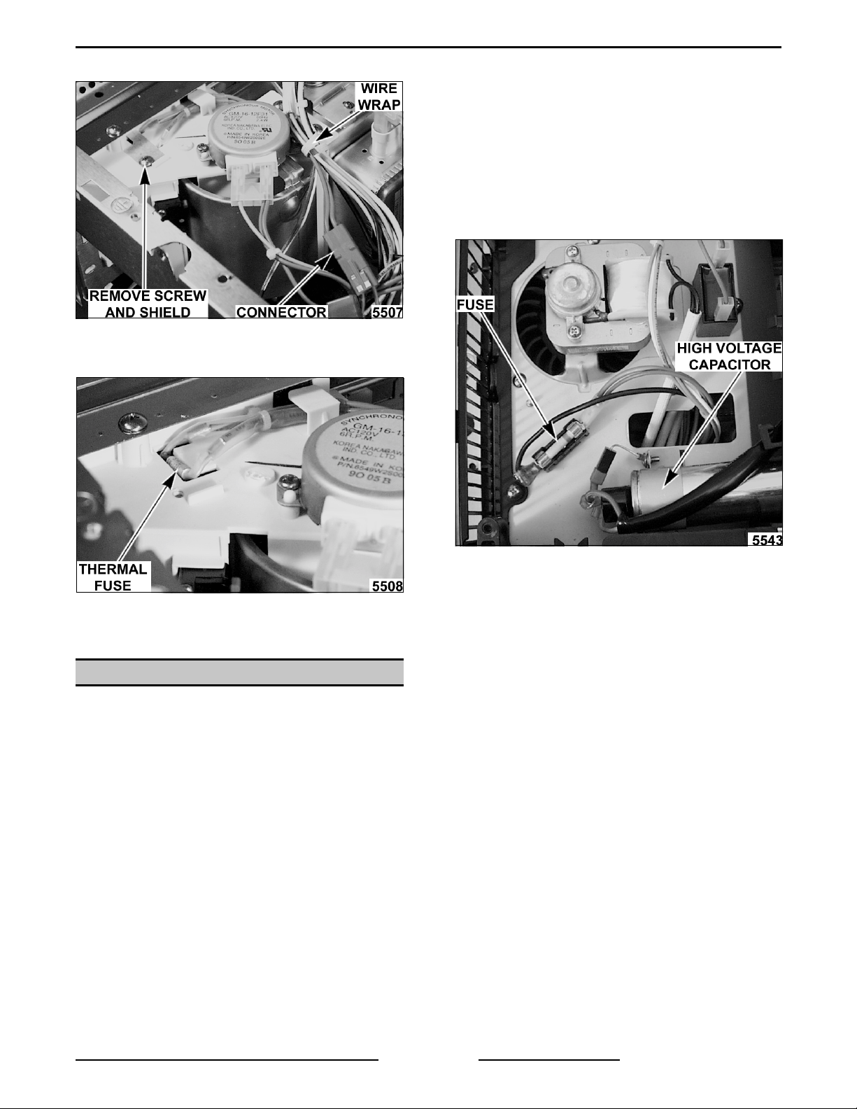
7. Undo wire wrap and work wires out.
WARNING:
POWER TO T HE MACHINE AT THE MAIN
CIRCUIT BO X. P LA CE A TAG ON THE CI RCUIT
BOX INDICATING THE CIRCUIT IS BEING
SERVICED.
1. Remove "UPPER LAMP HOUSING AND
DUCT ASSEMBLY.”
2. Remove connector from l amp door switch.
3. Remove connector from l amp socket.
DISCONNECT THE ELECTRICAL
8. Remove sc rew secu ring lamp soc ket.
NOTE:
9. If door is to be removed, first remove motor
Lamp and socket are r eplaced as one piece.
and then remove screw securing bott om of
door.
4. Remove one screw securing assembly to top of
cavity.
5. Remove two screws securing assembly to top
of m agnetron.
NOTE:
different.
6. Disconnect motor connector and thermal fuse
Form 24694 ( A pr il 2001) Page 10 of 52
Screws removed from magnetron ar e
connector.
10. Reverse procedure to install.
WARNING:
POWER TO T HE MACHINE AT THE MAIN
CIRCUIT BO X. P LA CE A TAG ON THE CI RCUIT
BOX INDICATING THE CIRCUIT IS BEING
SERVICED.
1. Remove "UPPER LAMP HOUSING AND
2. Disconnect thermal fuse connector.
3. Undo wire wrap and work wires out.
DAMPER HOUSING THERMAL
FUSE
DISCONNECT THE ELECTRICAL
DUCT ASSEMBLY.”
FLASHBAKE® / MICROWAVE O VEN REMOVAL AND REPLACEMENT OF PARTS
4. Remove screw and shield.
5. Slide fuse out of slot.
WARNING:
CARE SHOULD BE TAKEN WHEN MEASURING
AROUND THE MAGNETRON.
1. Remove "MAIN COV E R.”
2. Discharge high voltage capacitor by short ing
the term inals of the high v oltage capaci tor with
an insulated handled screwdriver or insulated
jumper wi r e.
3. Remove fuse f r om holder.
DUE TO HIGH VOLTAGE, SPECIAL
6. Reverse proc edur e to install .
FUSE - 20 AMP
WARNING:
POWER TO T HE MACHINE AT THE MAIN
CIRCUIT BO X. P LA CE A TAG ON THE CI RCUIT
BOX INDICATING THE CIRCUIT IS BEING
SERVICED.
Important Note:
due to the operation of the monitor switc h, check the
following components and replace the ones found t o
be malfunctioning.
A. Door prim ary interlock switch.
B. Door secondary inter lock switch.
C. Door monitor switch.
NOTE:
cover and after al l necessary components are
replaced and adjust ed, a radiati on leak test MUST
be performed in the magnetron area.
DISCONNECT THE ELECTRICAL
When the 20 amp f use i s blown
During reassembl y , before i nstalling main
MODEL FBMW2 SHOWN
4. Reverse proc edur e to install .
Form 24694 ( A pr il 2001)Page 11 of 52
FLASHBAKE® / MICROWAVE O VEN REMOVAL AND REPLACEMENT OF PARTS
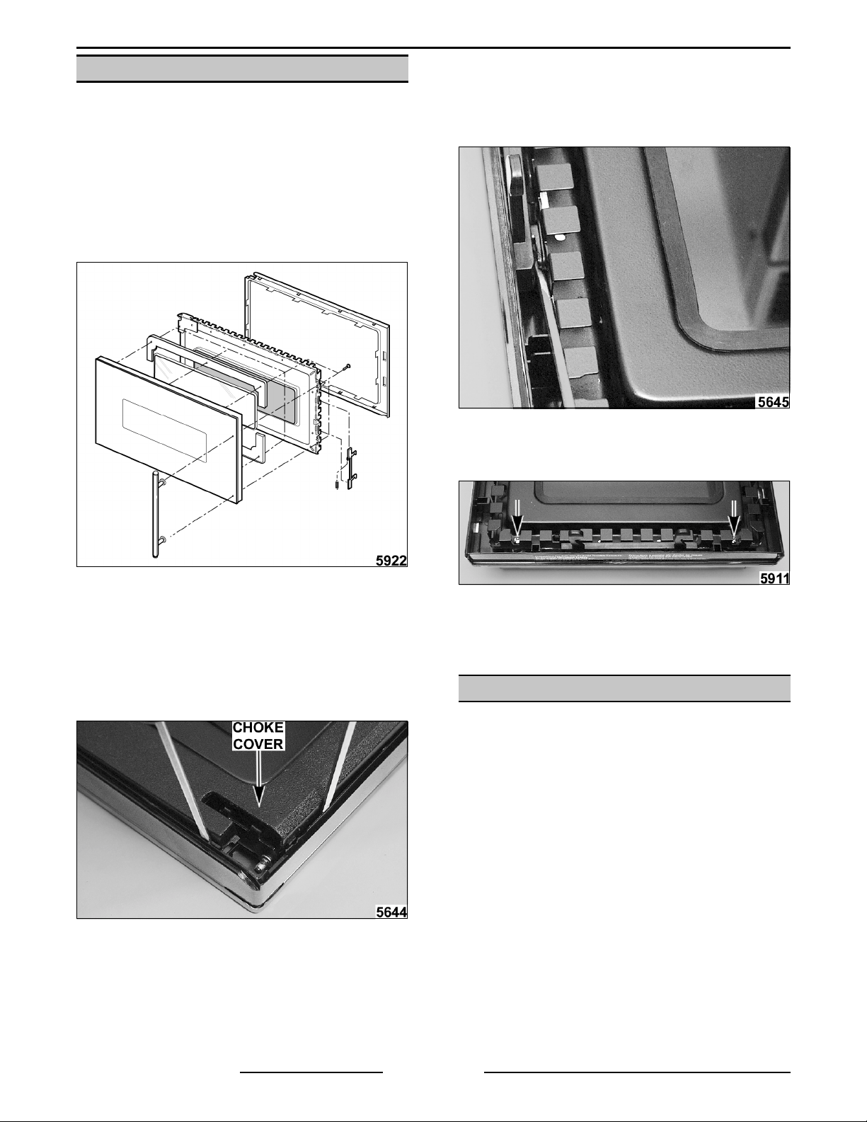
DOOR
WARNING:
POWER TO T HE MACHINE AT THE MAIN
CIRCUIT BO X. P LA CE A TAG ON THE CI RCUIT
BOX INDICATING THE CIRCUIT IS BEING
SERVICED.
1. Open door.
2. Lift door to disengage hinge pins from holes in
hinges and remove door.
DISCONNECT THE ELECTRICAL
B. The latch c an be removed by pushing it
against spring tensi on to the end of its
travel. Then pry latch out of mounting
holes and lift it up enough to be able to
disconnect the spring.
C. Remove door handle by removing screws
securing it .
EXPLODED VIEW OF DOOR ASSEMBLY
3. To replace door handle, door lat c h:
A. Insert small flat type screwdriver into gap
between choke cover and lower right
corner of the door frame fi rst and then
around the seal plate to free engaging
parts of choke cover.
4. Reverse proc edur e to install .
5. Perform "RADIATION LEAKAGE TEST.”
CONTROL PANEL ASSEMBLY
WARNING:
POWER TO T HE MACHINE AT THE MAIN
CIRCUIT BO X. P LA CE A TAG ON THE CI RCUIT
BOX INDICATING THE CIRCUIT IS BEING
SERVICED.
CAUTION: Certain components in this system
are subject to damage by electrostatic discharge
during field repairs. A field service grounding kit
is available to prevent damage. T he field servi ce
grounding kit must be used anytime the control
board is handled.
Control Panel
1. Remove “FRONT VENT GRILL.”
DISCONNECT THE ELECTRICAL
Form 24694 ( A pr il 2001) Page 12 of 52
FLASHBAKE® / MICROWAVE O VEN REMOVAL AND REPLACEMENT OF PARTS
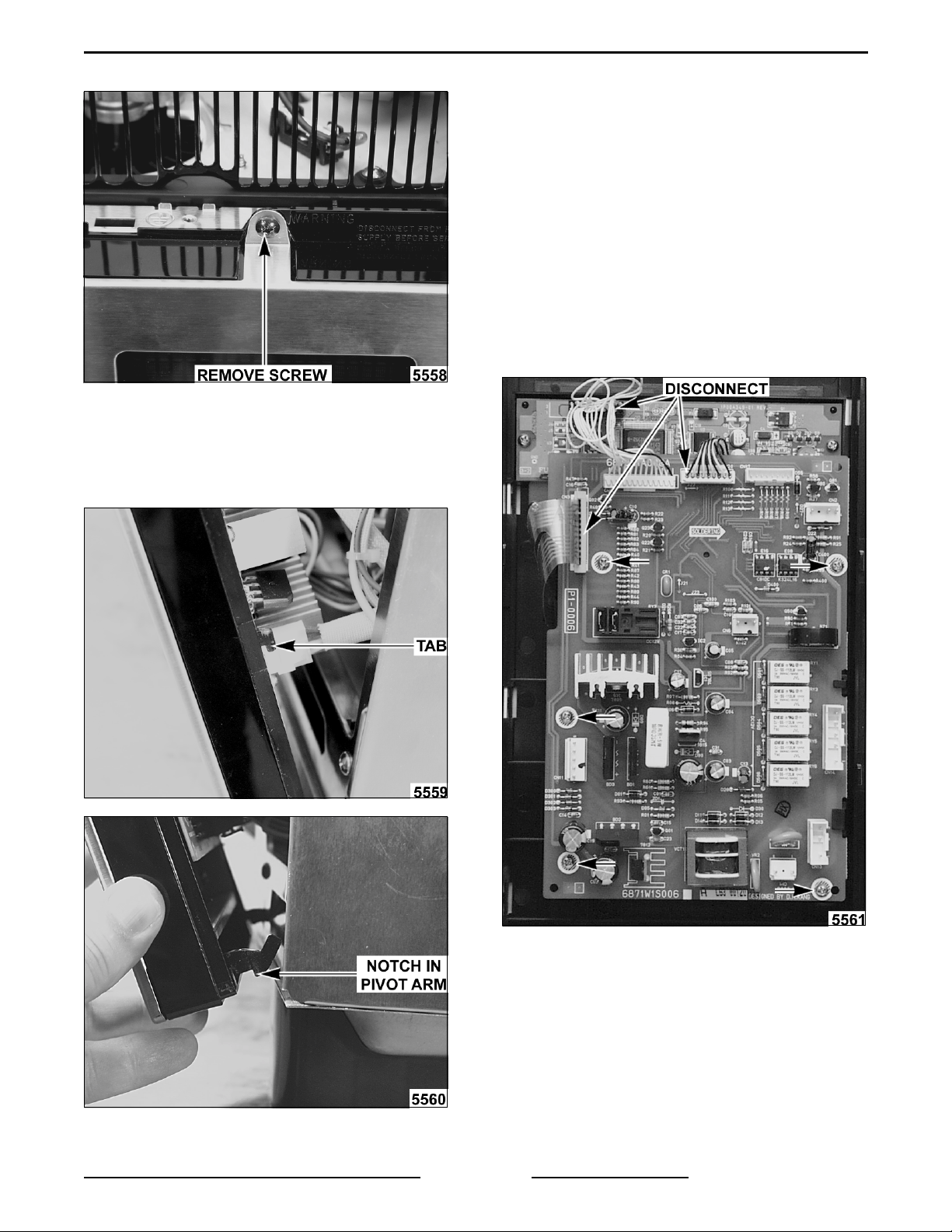
2. Remove screw securing top of c ontrol panel.
3. Open ov en door .
4. Lift control panel about 1/8" to disengage tabs
at both sides of panel and notch on bottom
pivot arms.
6. Disconnect ei ght plugs from control boar d.
CAUTION: Wh en reassembling, be certain all
plugs are correctly mated. If plug is colored,
connect i t to same colo r connector o n board.
Failure to connect correctly will result in
damage to unit.
7. Lift panel and work pivot arms out of holes and
remove panel from unit.
Control Board
1. Remove "CONTROL PANEL.”
2. Disconnect connectors going to display boar d,
LED board and keyswitch board.
3. Remove fi ve screws securing control board and
remove board.
5. Allow panel to tilt forward.
Form 24694 ( A pr il 2001)Page 13 of 52
FLASHBAKE® / MICROWAVE O VEN REMOVAL AND REPLACEMENT OF PARTS
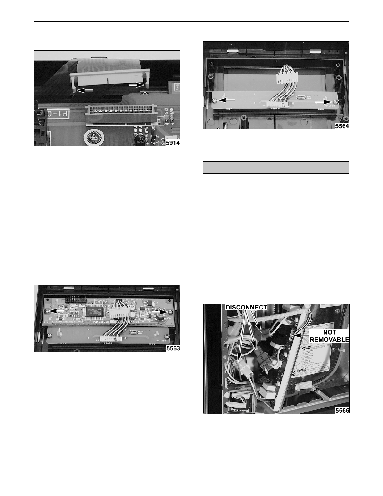
NOTE:
each side that must be released in order to
completely disconnect.
4. Reverse proc edur e to install .
The keypad connector has a locking tab on
3. Remove two screws securing LED display
assembly and remove assembly.
4. Reverse proc edur e to install .
RELAY BOARD
Keypad Assembly
1. Remove "CONTROL BOARD.”
2. Remove “DISPLAY.”
3. Remove “LED DISPLAY.”
4. Reverse proc edur e to install .
Display
1. Remove "CONTROL BOARD.”
2. Remove two screws securing display board and
remove board.
3. Reverse proc edur e to install .
WARNING:
POWER TO T HE MACHINE AT THE MAIN
CIRCUIT BO X. P LA CE A TAG ON THE CI RCUIT
BOX INDICATING THE CIRCUIT IS BEING
SERVICED.
1. Remove "MAIN COV E R.”
2. Remove "CONTROL PANEL.”
3. Disconnect two blue c onnec tors on wires
coming from relay board.
4. Disconnect white c onnec tor on wires coming
from relay board.
NOTE:
removable.
DISCONNECT THE ELECTRICAL
Connector CN100 on relay board is not
LED Displ ay
1. Remove "CONTROL BOARD.”
2. Remove “DISPLAY.”
Form 24694 ( A pr il 2001) Page 14 of 52
FLASHBAKE® / MICROWAVE O VEN REMOVAL AND REPLACEMENT OF PARTS
5. Remove two screws securing relay board to
board support and work relay board out of
support.
3. Remove two screws securing assembly to unit.
6. Reverse proc edur e to install .
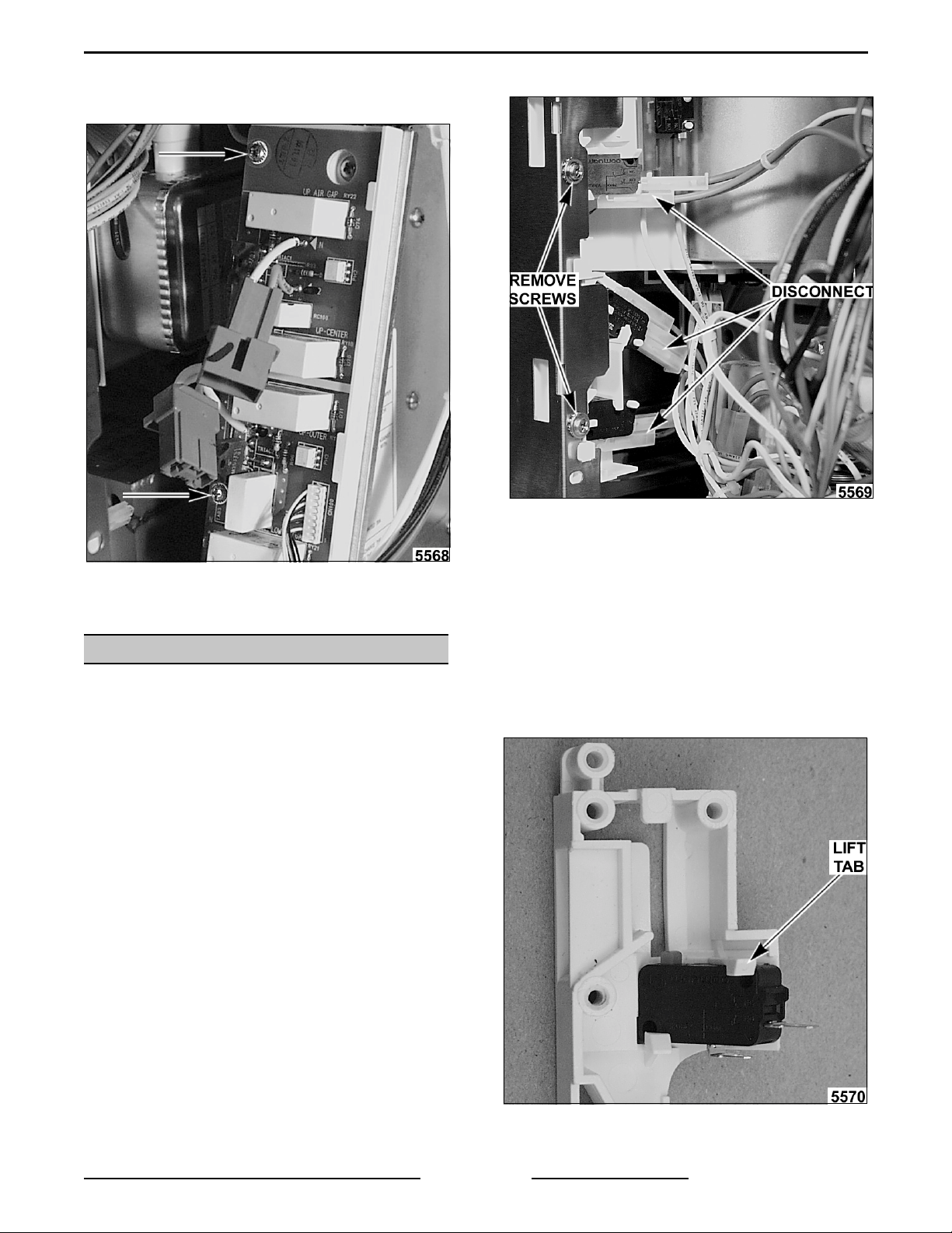
DOOR SWITCH A SSEMBLY
WARNING:
POWER TO T HE MACHINE AT THE MAIN
CIRCUIT BO X. P LA CE A TAG ON THE CI RCUIT
BOX INDICATING THE CIRCUIT IS BEING
SERVICED.
1. Remove "CONTROL PANEL.”
2. Identify and disconnect connectors from the
three switches.
DISCONNECT THE ELECTRICAL
4. Careful ly slide assembly up to disengage tabs
and rotate assembl y out of unit.
5. Remove a switch by pressing appropri ate tab to
release switch.
CAUTION: Flex tabs only enough to release
switch. Excessive flexing will result in tab
breaking.
A. For top switch (primary interlock switch),
lift tab away fr om switch and slide switc h
out.
Form 24694 ( A pr il 2001)Page 15 of 52
FLASHBAKE® / MICROWAVE O VEN REMOVAL AND REPLACEMENT OF PARTS
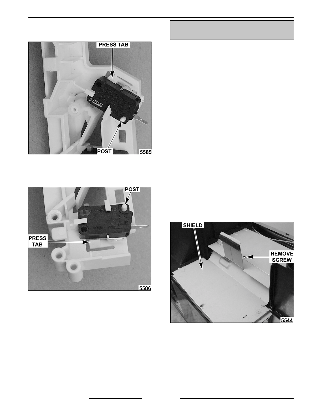
B. For middle switch (i nterlock monitor
switch), press tab downward and then
pivot switch to clear stops and lift off post.
UPPER LAMP HOUSING AND
DUCT ASSEMBLY
Parts that can be ac c essed when upper lam p
housing and duct assembly is removed:
• Cavity thermistor.
• Thermal cut out located at top of magnetron.
• Magnetron.
• Upper lamp assem bly.
• Upper lamp fan assembly.
• Damper door assembly.
• Magnetron f an assem bly.
• Lower lamp fan assembly.
• High voltage transformer.
C. For bottom switch (door sensing
secondary interlock switch), press tab
downward and then pivot switch to clear
stops and lift off post.
6. Reverse proc edur e to install .
WARNING:
POWER TO T HE MACHINE AT THE MAIN
CIRCUIT BO X. P LA CE A TAG ON THE CI RCUIT
BOX INDICATING THE CIRCUIT IS BEING
SERVICED.
1. Remove "MAIN COV E R.”
2. Remove "VENT FAN.”
3. Remove "BACK PANEL.”
4. Remove screw securing shield and remove
shield.
DISCONNECT THE ELECTRICAL
7. Adjust as outlined in service procedures and
adjustment s "DOOR LATCH.”
8. Perform leakage test .
5. Discharge high voltage capacitor by short ing
Form 24694 ( A pr il 2001) Page 16 of 52
the term inals of the high v oltage capaci tor with
an insulated handled screwdriver or insulated
jumper wi r e.
 Loading...