

Vulcan-Hart ML-44963Z, ML-44909Z, VCB36C, VCB36 ML-44966, ML-44964Z Installation & Operation Manual
...Page 1
INSTALLATION &
OPERATION MANUAL
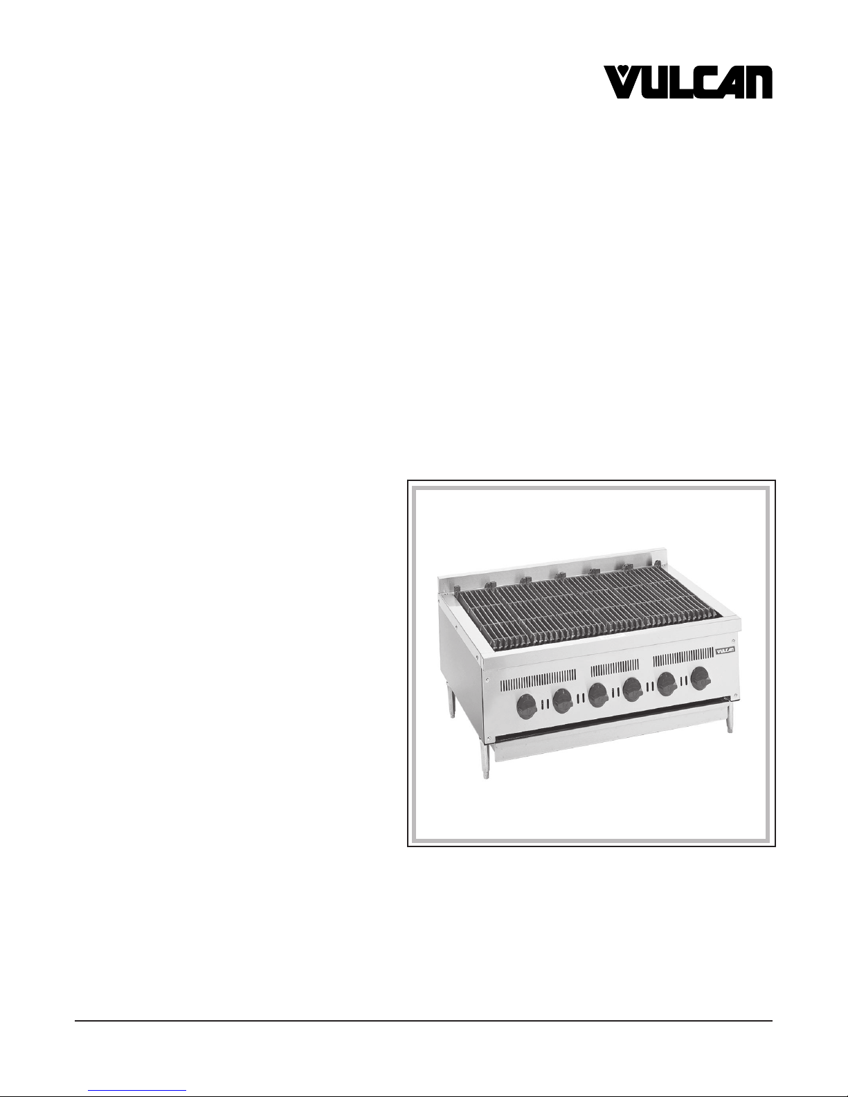
VCB25, VCB36, VCB47 SERIES
CHARBROILERS
MODELS
VCB25S ML-44908Z
VCB25M ML-44963Z
VCB36 ML-44966
VCB36S ML-44909Z
VCB36C ML-44967
VCB36M ML-44964Z
VCB47S ML-44910Z
VCB47M ML-44965Z
Model VCB36C
VULCAN-HART COMPANY, P.O. BOX 696, LOUISVILLE, KY 40201-0696, TEL. (502) 778-2791
FORM 31167 (Jan. 2001)
– 1 –
Page 2
IMPORTANT FOR YOUR SAFETY
THIS MANUAL HAS BEEN PREPARED FOR PERSONNEL QUALIFIED TO INSTALL GAS
EQUIPMENT, WHO SHOULD PERFORM THE INITIAL FIELD START-UP AND
ADJUSTMENTS OF THE EQUIPMENT COVERED BY THIS MANUAL.
POST IN A PROMINENT LOCATION THE INSTRUCTIONS TO BE FOLLOWED IN THE
EVENT THE SMELL OF GAS IS DETECTED. THIS INFORMATION CAN BE OBTAINED
FROM THE LOCAL GAS SUPPLIER.
IMPORTANT
IN THE EVENT A GAS ODOR IS DETECTED, SHUT
DOWN UNITS AT MAIN SHUTOFF VALVE AND
CONTACT THE LOCAL GAS COMPANY OR GAS
SUPPLIER FOR SERVICE.
FOR YOUR SAFETY
DO NOT STORE OR USE GASOLINE OR OTHER
FLAMMABLE VAPORS OR LIQUIDS IN THE
VICINITY OF THIS OR ANY OTHER APPLIANCE.
WARNING
IMPROPER INSTALLATION, ADJUSTMENT,
ALTERATION, SERVICE OR MAINTENANCE CAN
CAUSE PROPERTY DAMAGE, INJURY OR DEATH.
READ THE INSTALLATION, OPERATING AND
MAINTENANCE INSTRUCTIONS THOROUGHLY
BEFORE INSTALLING OR SERVICING THIS
EQUIPMENT.
IN THE EVENT OF A POWER FAILURE, DO NOT
ATTEMPT TO OPERATE THIS DEVICE.
© VULCAN-HART COMPANY, 2001
– 2 –
Page 3

INSTALLATION, OPERATION AND CARE OF
MODEL VCB SERIES CHARBROILERS
PLEASE KEEP THIS MANUAL FOR FUTURE USE
GENERAL
Vulcan-Hart Charbroilers are produced with quality workmanship and material. Proper installation,
usage and maintenance of your charbroiler will result in many years of satisfactory performance.
It is suggested that you thoroughly read this entire manual and carefully follow all of the instructions
provided.
INSTALLATION
Before installing, verify that the type of gas supply (natural or propane) agrees with the specifications
on the rating plate located on the right inside panel. If the supply and equipment requirements do not
agree, do not proceed with the installation. Contact your dealer or Vulcan-Hart Company immediately.
UNPACKING
This charbroiler was inspected before leaving the factory. The transportation company assumes full
responsibility for safe delivery upon acceptance of the shipment. Immediately after unpacking, check
for possible shipping damage. If the charbroiler is found to be damaged, save the packaging material
and contact the carrier within 15 days of delivery.
Carefully unpack charbroiler and place in a work-accessible area as near to its final installed position
as possible.
LOCATION
The equipment area must be kept free and clear of combustible substances.
This charbroiler is design certified for installation on a non-combustible counter with 4" (10 cm) legs,
or on a combustible floor with a 24" (61 cm) high cabinet or stand with the following minimum clearances
to adjacent wall construction:
ecnaraelCmuminiM
:morF
kcaB
sediS
leveLdirGevobA
leveLdirGwoleB
leveLdirGevobA
leveLdirGwoleB
elbitsubmoC
noitcurtsnoC
)mc03("21
)mc8("3
)mc32("9
)mc8("3
"0
"0
elbitsubmoC-noN
noitcurtsnoC
)mc8("3
)mc8("3
– 3 –
Page 4

Floor models must clear 6" (15 cm) from combustible oors.
In the United States of America:
1. State and local codes.
2. National Fuel Gas Code, ANSI/Z223.1/NFPA #54 (latest edition). Copies may be obtained
from The American Gas Association, Accredited Standards Committee Z223 @ 400 N. Capital
St. NW, Washington, DC 2001 or the Secretary Standards Council, NFPA, 1 Batterymarch
Parch Quincy MA 02169-7471.
NOTE: In the Commonwealth of Massachusetts,
All gas appliances vented through a ventilation hood or exhaust system equipped with a
damper or with a power means of exhaust shall comply with 248 CMR.
3. Vapor Removal From Cooking Equipment, NFPA #96 (latest edition). Copies may be obtained
from The National Fire Protection Association, Batterymarch Park Quincy MA 02169-7471.
4. National Electrical Code, ANSI/NFPA-70 (latest edition). Copies may be obtained from The
National Fire Protection Association, Batterymarch Park, Quincy MA 02169-7471.
It is recommended that the charbroiler NOT be installed next to open burners or fryers.
The installation location must allow adequate clearances for servicing and proper operation. A
minimum front clearance of 24" (61 cm) is required.
Do not obstruct the ow of combustion and ventilation air. Adequate clearance for air openings into the
combustion chamber must be provided. Make sure there is an adequate supply of air in the room to
replace air taken out by the ventilating system. Do not permit fans to blow directly at the charbroiler.
Avoid wall-type fans which create air cross currents within the room.
Avoid open windows next to the charbroiler.
INSTALLATION CODES AND STANDARDS
In Canada:
1. Local codes.
2. CAN/CGA-B149.1 Natural Gas Installation Code (latest edition).
3. CAN/CGA-B149.2 Propane Installation Code (latest edition), available from The Canadian Gas
Association, 178 Rexdale Blvd., Etobicoke, Ontario, Canada M9W 1R3.
CHARBROILERS MOUNTED ON A CABINET, STAND, OR OVEN BASE WITH CASTERS
When the charbroiler is mounted on a cabinet, stand, or oven base equipped with casters, it must be
installed with the casters supplied, a connector (not supplied by Vulcan-Hart) complying with either
ANSI Z21.69 (latest edition) or CAN/CGA-6.16 (latest edition), and a quick-disconnect device
complying with either ANSI Z21.41 (latest edition) or CAN1-6.9 (latest edition). Provide a gas line strain
relief to limit movement of the appliance without depending on the connector and any quick-disconnect
device or its associated piping to limit movement of the appliance.
Should it be necessary to disconnect the strain relief, turn o the gas supply before disconnection.
Reconnect the strain relief before turning the gas supply on and returning the broiler to its installation
position.
LEVELING
Place a carpenter's level on the charbroiler. Level the charbroiler front to back and side to side. Unless
the charbroiler is level, it will not give proper cooking results.
Casters for the cabinet, stand, or oven base on which the charbroiler can be mounted are of the nonadjustable type. Therefore, the oor must be level. If oor surface is not level, the charbroiler will
experience cooking problems.
– 4 –
Page 5

GAS CONNECTIONS
CAUTION: Gas supply connections and any pipe joint compound must be resistant to the action
of propane gases.
Location of the gas inlet is at the right rear corner. Codes require that a gas shutoff valve must be
installed in the gas line ahead of the charbroiler.
Connect gas supply to the charbroiler. Make sure the pipes are clean and free of obstructions.
The gas supply line must be
diameter must be the equivalent of
3
/4" or larger. If flexible or semi-rigid connections are used, the inside
3
/4" iron pipe or larger.
Natural gas pressure regulators are preset for 5" W.C. (Water Column); propane gas pressure
regulators are preset for 10" W.C. A pressure regulator is supplied and must be installed outside the
charbroiler when it is connected to the gas supply.
All orifices are of the fixed type and require no adjustments.
WARNING: PRIOR TO LIGHTING, CHECK ALL JOINTS IN THE GAS SUPPLY LINE FOR LEAKS.
USE SOAP AND WATER SOLUTION. DO NOT USE AN OPEN FLAME.
After piping has been checked for leaks, all piping receiving gas should be fully purged to remove air.
TESTING THE GAS SUPPLY SYSTEM
When gas supply pressure exceeds
1
/2 psig (3.45 kPa), the charbroiler and its individual shutoff valve
must be disconnected from the gas supply piping system.
When gas supply pressure is
1
/2 psig (3.45 kPa) or less, the charbroiler should be isolated from the gas
supply system by closing its individual manual shutoff valve.
FLUE CONNECTIONS
DO NOT obstruct the flow of flue gases from the flue located on the rear of the charbroiler. It is
recommended that the flue gases be ventilated to the outside of the building through a ventilation
system installed by qualified personnel.
From the termination of the flue to the filters of the hood venting system, a minimum clearance of 18"
(46 cm) must be maintained.
Information on the construction and installation of ventilating hoods may be obtained from the standard
for "Vapor Removal from Cooking Equipment," NFPA No. 96 (latest edition), available from The
National Fire Protection Association, Batterymarch Park, Quincy, MA 02269.
– 5 –
Page 6

OPERATION
WARNING: THE CHARBROILER AND ITS PARTS ARE HOT. BE VERY CAREFUL WHEN
OPERATING, CLEANING OR SERVICING THE CHARBROILER.
CONTROLS
Gas Valves — Regulate gas flow to the burners.
Pilot Adjusting Valve — Regulates gas flow to pilot burner.
Gas Pressure Regulator — Regulates gas pressure to the burners.
LIGHTING INSTRUCTIONS
1. Turn gas shutoff valve and burner gas valves to the OFF position and wait 5 minutes.
2. Turn the gas shutoff valve to the ON position.
3. Turn pilot valve adjusting valve counterclockwise. Light the pilot adjacent to each burner. Adjust
the pilot screw until the pilot flame is
1
/4" (6 mm) high. The flame should have a slight yellow tip.
Light pilots through observation holes provided on front face of burner box.
4. Turn the burner gas valve to the ON position.
5. Air shutters on the burners must be individually adjusted to provide a blue flame. Adjust all traces
of yellow out of the burner flame.
6. For complete shutdown, turn the gas shutoff valve, burner gas valves, and the pilot adjustment
valves to the OFF position.
7. To relight, follow steps 1-4.
GRATE POSITION
The cast iron grates are positioned to lay flat for stock pot use and for cleaning. For broiling, reverse
grates to slope forward. If you need an extra griddle for your rush hour periods, a lift-off griddle is
available as an optional extra.
PREHEATING
Allow charbroiler to preheat approximately 30 minutes with burners full-on. Rub grates with grease
before using. The excess grease will run forward and drip onto the front grease trough.
OPERATING THE CHARBROILER
1. Load charbroiler.
2. Turn burners down to prevent overheating which causes the meat to overchar.
3. Scrape the grates with a wire brush during broiling to keep the grates clean. Do not allow debris
to accumulate on the grates.
4. Turn burners to low setting during slack periods to conserve energy.
– 6 –
Page 7

The charbroiler is a free-vented appliance. All the products of combustion and the heat generated by
the burners pass through the grates. When meat is placed on the grates, you are blocking the venting,
thus causing a temperature build-up. The charbroiler, with a complete load, will operate most efficiently
1
with burners turned down
/3 to 1/2.
DRIP PAN
DO NOT allow the drip pan to overflow. Empty the drip pan when three-quarters full to reduce the
possibility of spillage.
CLEANING
Daily
Thoroughly scrape grate so that grease flows into front grease trough and drip pan. This prevents flareups.
Grates may be laid in the flat position with burners full on to burn off fat and carbon. When grates have
cooled off, brush thoroughly with a steel brush.
Remove grates and front grease trough for thorough cleaning.
Remove and empty drip pan. Clean as you would any normal utensil. Rinse thoroughly and wipe dry
with a soft clean cloth.
Once charbroiler is clean, replace drip pan, grates, and front grease trough.
Clean stainless steel surfaces with a mild detergent and water, using a damp cloth, or with a
commercial stainless steel cleaner. Rinse thoroughly and wipe dry with a soft clean cloth.
Burner ports and throats should be thoroughly cleaned. Venturi must be free from grease and lint. DO
NOT insert pick in burner port hole.
Burner with baffle may be removed periodically for cleaning (use a wire brush).
– 7 –
Page 8

MAINTENANCE
WARNING: THE CHARBROILER AND ITS PARTS ARE HOT. BE VERY CAREFUL WHEN
OPERATING, CLEANING OR SERVICING THE CHARBROILER.
LUBRICATION
All moving parts must be checked for wear and lubricated. Contact your local Vulcan authorized
servicer.
All valves and controls should be lubricated with a high temperature grease by your local Vulcan
authorized servicer.
PILOT LIGHTS
Pilot lights are to be kept clean and adjusted.
RECOMMENDED SERVICE FREQUENCY
Frequency of service maintenance will be largely dependent upon customer usage.
10-12 hours operation per day, 7 days a week — Every 30-60 days
4-6 hours a day, 5 days a week — Every 120 days
Limited daily usage — Every 180 days
All equipment — At least once a year
SERVICE AND PARTS INFORMATION
To obtain service and parts information concerning this charbroiler, contact the Vulcan-Hart Service
Agency in your area (refer to listing supplied with the charbroiler), or Vulcan-Hart Company Service
Department at the address or phone number shown on the front cover of this manual.
FORM 31167 (Jan., 2001) PRINTED IN U.S.A.
– 8 –
 Loading...