

Page 1
SERVICE MANUAL
VC4E & VC6E
SERIES
FULL SIZE
ELECTRIC CONVECTION
OVENS
MODEL ML
VC4ES 126743
VC4ED 126744
VC4EC 126745
VC6ES 126746
VC4ED SHOWN
- NOTICE -
This Manual is prepared for the use of train ed Vulcan Service
Technicians and should not be used by those not properly
qualif ied. If you have att ended a Vu lcan Service School for this
product, you may be qualified to perform all the procedures
described in this man ual.
Thi s manu al i s no t i nten ded to be al l en comp assi ng . I f you have
not attende d a Vulcan S ervic e School for this produc t, you sho uld
read, in its entirety, the repair procedure you wish to perform to
determine if you have the necessary tools, instruments and skills
required to perform the procedure. Procedures for which you do
not have th e necessary tools, instruments and skills should be
performed b y a trained Vu lcan Service Technician .
VC6ED 126747
VC6EC 126748
Reproduction or other use of this Manual, without the express
written consent of Vulcan, is prohibited
A product of VULCAN-HART LOUISVILLE , KY 40201-0696
.
F25105 (Decem ber 2001)
Page 2

FULL SIZE ELECTRIC CONVECTION OVENS
TABLE OF CONTENTS
GENERAL............................................................................. 4
Introduction ........................................................................ 4
Installation......................................................................... 4
Operation.......................................................................... 4
Cleaning .......................................................................... 4
Lubrication ......................................................................... 4
Tools ............................................................................. 4
Specifications ...................................................................... 5
REMOVAL AND REPLACEMENT OF PARTS ................................................. 6
Covers And Panels .................................................................. 6
Control Panel Components ............................................................ 7
Component Panel Components ......................................................... 8
Temperat ure Probe (Solid State Control) .................................................. 8
Heating Elements ................................................................... 9
Blower And Motor .................................................................. 10
Door Switch ....................................................................... 11
Door W indow ...................................................................... 12
Ov en Door s and Bear ings (Independent Doors) ............................................ 12
Ov en Door s (S imultaneous Doors) ...................................................... 13
Door Catch Roller Assembly (Independent Doors) .......................................... 14
Mechanical (KX) Thermostat .......................................................... 14
High Limit Thermostat ............................................................... 15
Interior Lights...................................................................... 15
Cooling Fan ....................................................................... 16
SERVICE PROCEDURES AND ADJUSTMENTS .............................................. 17
Solid State Temperature Control Calibration .............................................. 17
Mechanical (KX) Thermostat Calibration ................................................. 18
Solid State Temperature Control Test ................................................... 19
Temperat ure Probe Test (Sol id State Contr ol) ............................................. 20
Heating Element Test ............................................................... 20
Blower Adjustment.................................................................. 21
Door Adjustment ................................................................... 22
Door Catch Roller Adjustment (Independent Doors) ......................................... 22
Door Switch Adjustment.............................................................. 23
Door Chain Adjustment (Simultaneous Doors) ............................................. 23
Computer Control .................................................................. 24
Computer Control Temperature Calibration ............................................... 26
Computer Cont rol Operational Test ..................................................... 26
ELECTRICAL OPERATION .............................................................. 29
Component Func tion ................................................................ 29
Component Locat ion ................................................................ 30
Sequence of O per ation .............................................................. 34
VC4ES, VC6ES wi th Mechanical K X Ther mostat ....................................... 34
VC4ED, VC6ED with Solid State Temperature Control................................... 34
Timer Cycle, Cooking (KX Thermostat or Solid State Control) ............................. 35
Cool Down Cycle (KX Thermostat or Solid State Control)................................. 35
VC4EC, VC6EC (Computer Control) ................................................ 35
Temperat ure and Tim e Cy c le (Cooking) .......................................... 36
Cook and Hold Cycl e ........................................................ 36
Cool Down Cycle ........................................................... 36
Schematics ....................................................................... 37
VC4ES, VC6ES wi th Mechanical ( K X) Cont r ols, 208-240V ................................ 37
VC4ES, VC6ES wi th Mechanical ( K X) Cont r ols, 480V ................................... 38
VC4ED, VC6ED wit h S olid Stat e Temperature Control, 208-240V .......................... 39
VC4ED, VC6ED wit h S olid Stat e Temperature Control, 480V .............................. 40
F25105 (Decem ber 2001) Page 2 of 60
Page 3

FULL SIZE ELECTRIC CONVECTION OVENS
VC4EC, VC6EC Computer Control, 208-240V (Roast & Hol d S tandard) ...................... 41
VC4EC, VC6EC Computer Control, 480V (Roast & Hold S tandard) ......................... 42
Wiring Diagrams ................................................................... 44
VC4ES, VC6ES wi th Mechanical ( K X) Cont r ol, 208-240V ................................. 44
VC4ES, VC6ES wi th Mechanical ( K X) Cont r ol, 480V .................................... 46
VC4ED, VC6ED wit h S olid Stat e Temperature Control, 208-240V .......................... 48
VC4ED, VC6ED wit h S olid Stat e Temperature Control, 480V .............................. 50
VC4EC, VC6EC Computer Control, 208-240V (Roast & Hol d S tandard) ...................... 52
VC4EC, VC6EC Computer Control, 480V (Roast & Hold S tandard) ......................... 54
TROUBLESHOOTING .................................................................. 56
All Models ........................................................................ 56
Computer Cont rol Models Only ........................................................ 57
CONDENSED SPARE PARTS LIST ........................................................ 60
© Vulcan 2001
F25105 (Decem ber 2001)Page 3 of 60
Page 4
FULL SIZE ELECTRIC CONVECTION OVEN - GENERAL
GENERAL
INTRODUCTION
Procedures in this manual will apply to all models unless specified. Pictur es and illustrations can be of any model
unless the picture or illustration needs to be model specific.
Models
FEATURES OPTIONS
MODEL
VC4ES
VC4ED
VC4EC
VC6ES
VC6ED
VC6EC
NOTES
4
4
:
CAVITY
DEPTH
26.5" Mechanical (KX) Independent
26.5" Solid State Independent
26.5" Computer Independent
30.5" Mechanical (KX) Independent
30.5" Solid State Independent
30.5" Computer Independent
1. Sim ultaneous doors are optional (with or w/o window).
2. Stainless steel doors w/o window (standard).
3. Stainless steel doors with window (standard)
4. In February 2001, this model was discontinued.
TEMPERATURE
CONTRO L
DOORS
(50/50)
TIMER
1, 2
1-Hour Dial 5-Hour Dial N/A
1, 3
1-Hour Dial 5-Hour Dial N/A
1, 3
24-Hour Digital Built in Built in
1, 2
1-Hour Dial 5-Hour Dial N/A
1, 3
1-Hour Dial 5-Hour Dial N/A
1, 3
24-Hour Digital Built in Built in
COOK
COOK
TIMER
COOK &
HOLD
INSTALLATION
Refer to the Instructions Manual for detailed
installation instr uc tions on single or stacked ovens.
OPERATION
Refer to the Instructions Manual for specific
operating i nst r uc tions.
CLEANING
Refer to the Instructions Manual for specific
cleaning instructions.
LUBRICATION
Cavity blower m otor has sealed bearings and
requires no addit ional lubrication.
Huskey’s TF1000 grease or equivalent high
temperat ure Teflon grease.
TOOLS
Standard
Standard set of hand tools
VOM with A. C. current tester ( A ny quality VOM
with a sensitivit y of at least 20,000 ohms per volt
can be used)
Gear Puller to rem ove blower
Temperat ure tester (thermocouple type)
Special
Manometer
Clamp on amp meter
Spring force gauge, pull type with a minimum 30
pound full scale range (purchase l oc ally)
RTV sealant, 736 DOW silicone high t emp
(P/N 542133) or equivalent
F25105 (Decem ber 2001) Page 4 of 60
Page 5
Electrical
FULL SIZE ELECTRIC CONVECTION OVEN - GENERAL
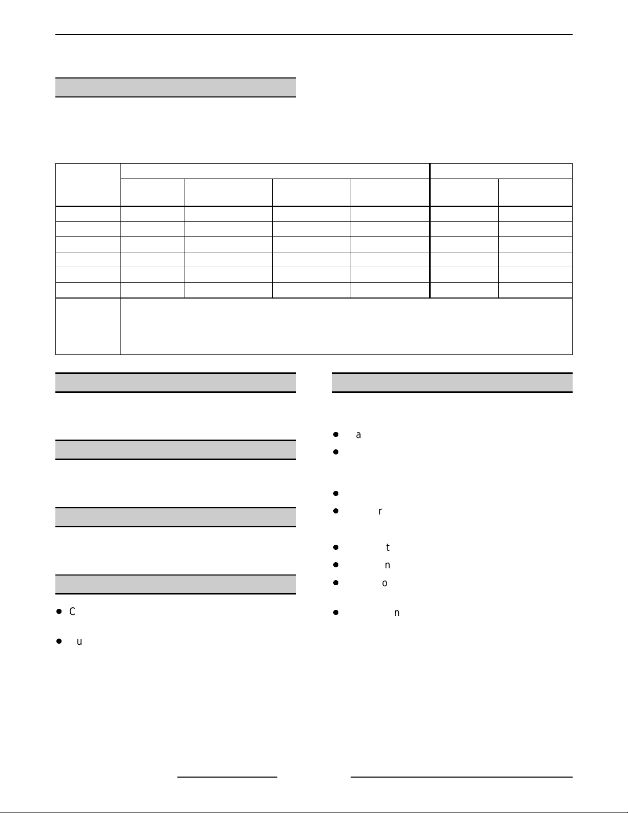
SPECIFICATIONS
AMPERAGE - 3 PHASE/ 60HZ
MODEL
VC4ES
VC4ED
VC4EC
VC6ES
VC6ED
VC6EC
NOTES:
MODEL
TOTAL
POWER
(KW)
PER LINE
1
RECOMMENDED
CIRCUIT
PROTECTION
2
208V 240V 480V 208V 240V 480V
12.5 353315454020
1. Amperage values in the table are nominal.
Tolerance is +5/-10%.
2. Complied in accordance wi th National E lectric Code,
ANSI/NFPA 70, latest edition.
AMPERAGE - 1 PHASE/ 60HZ
TOTAL
POWER
(KW)
PER LINE
1
RECOMMENDED
CIRCUIT
PROTECTION
2
VC4ES
VC4ED
VC4EC
VC6ES
VC6ED
VC6EC
NOTES:
208V 240V 480V 208V 240V 480V
12.5 605226807035
1. Amperage values in the table are nominal.
Tolerance is +5/-10%.
2. Complied in accordance wi th National E lectric Code,
ANSI/NFPA 70, latest edition.
F25105 (Decem ber 2001)Page 5 of 60
Page 6
FULL SIZE ELECTRIC CONVECTION OVEN - REMOVAL AND REPLACEMENT OF PARTS
REMOVAL AND REPLACEMENT OF PARTS
COVERS AND PANELS
WARNING:
POWER TO T HE MACHINE AT THE MAIN
CIRCUIT BO X. P LA CE A TAG ON THE CI RCUIT
BOX INDICATING THE CIRCUIT IS BEING
SERVICED.
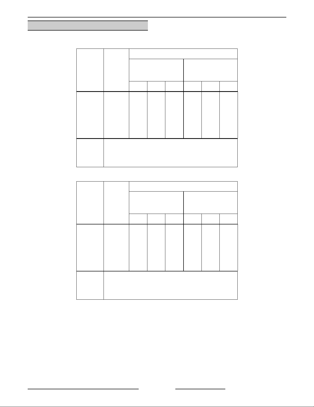
Top Front Cover
1. The top f r ont cover is secured with four ( 4)
screws, two on each side of cover. Rem ove
these screws then remove the cover from the
oven.
2. Reverse the procedure to install.
Bottom Front Cover
1. The bottom front c over i s secured wit h four (4)
screws, two on each side of cover. Rem ove
these screws then remove the cover from the
oven.
DISCONNECT THE ELECTRICAL
NOTE:
thermostat, it must be removed fr om the control
panel first, bef ore removing the control panel.
2. Disconnect the temperature pr obe leads from
3. Unplug the wire harness connector to the
4. Reverse the procedure to install.
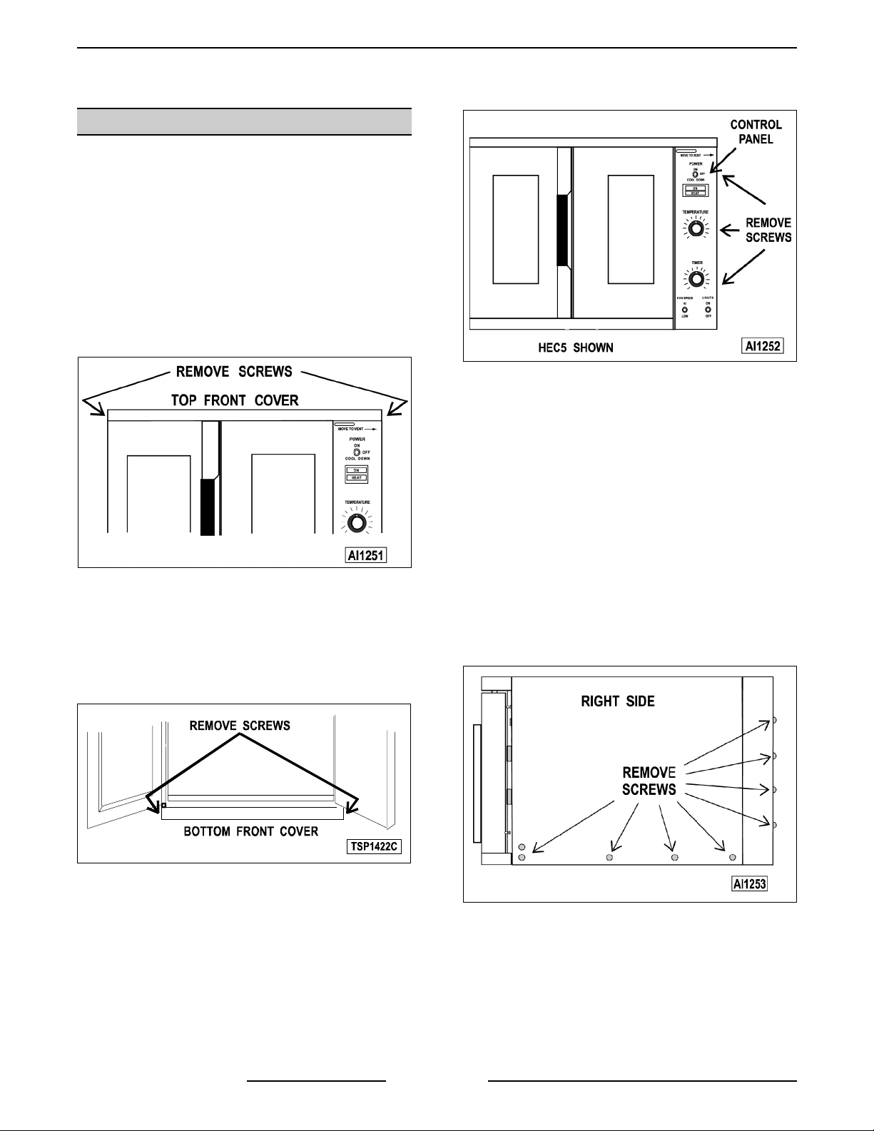
Right Side Panel
1. Remove the two screws near front of ov en,
2. Remove the remaining sev en scr ews securing
If t he oven has a mechanical (KX ty pe)
the solid stat e temperature c ontrol.
control panel components.
which secure the bottom front cover and c ontrol
panel.
the right side panel.
2. Reverse the procedure to install.
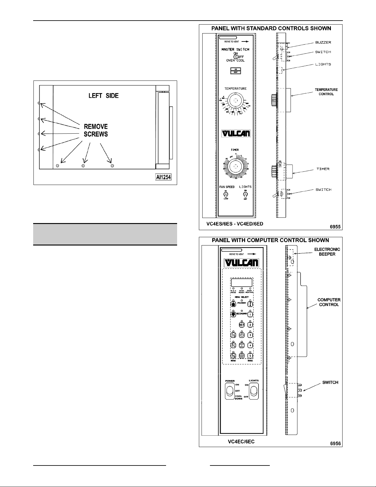
Control Panel
1. Remove three (3) screws on the right side
which secure the control panel then pul l the
panel away from the oven.
F25105 (Decem ber 2001) Page 6 of 60
3. Pull t he right side panel out at the bottom then
4. Reverse the procedure to install.
down to remove.
Page 7
FULL SIZE ELECTRIC CONVECTION OVEN - REMOVAL AND REPLACEMENT OF PARTS
Left Side Panel
1. Remove the screws which secure the left side
of the t op front cover, bot tom f r ont cover and
control panel.
2. Remove the seven screws securing t he left
side panel.
3. Pull t he left side panel out at the bottom then
down to remove.
4. Reverse the procedure to install.
CONTROL PANEL
COMPONENTS
WARNING:
POWER TO T HE MACHINE AT THE MAIN
CIRCUIT BO X. P LA CE A TAG ON THE CI RCUIT
BOX INDICATING THE CIRCUIT IS BEING
SERVICED.
Removable Components
1. Remove the control panel as outlined under
"COVERS AND PANELS".
2. Remove the component being replaced.
3. Reverse the procedure to install the
replacement component, then check oven for
proper operati on.
DISCONNECT THE ELECTRICAL
F25105 (Decem ber 2001)Page 7 of 60
Page 8
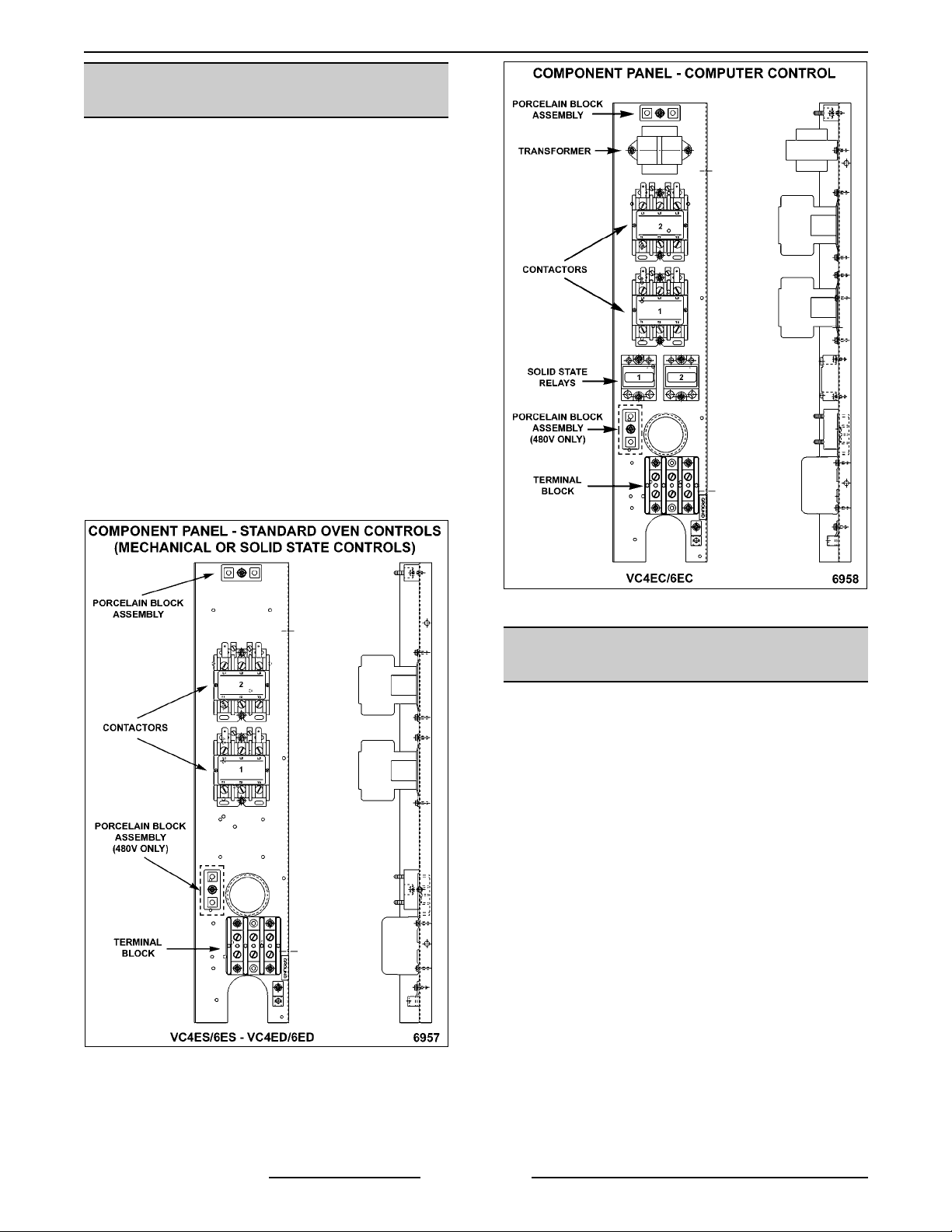
FULL SIZE ELECTRIC CONVECTION OVEN - REMOVAL AND REPLACEMENT OF PARTS
COMPONENT PANEL
COMPONENTS
WARNING:
POWER TO T HE MACHINE AT THE MAIN
CIRCUIT BO X. P LA CE A TAG ON THE CI RCUIT
BOX INDICATING THE CIRCUIT IS BEING
SERVICED.
Removable Components
1. Remove the right side panel as outli ned under
"COVERS AND PANELS".
NOTE:
component can be servic ed by r emov ing the control
panel as outli ned under "COVERS AND PA NE LS " .
2. Disconnect the wir e leads to the component
being replaced.
3. Remove the component.
4. Reverse the procedure to install the
replacement component and check oven for
proper operati on.
DISCONNECT THE ELECTRICAL
If right side panel is not accessible, t his
TEMPERATURE PROBE
(SOLID STATE CONTROL)
WARNING:
POWER TO T HE MACHINE AT THE MAIN
CIRCUIT BO X. P LA CE A TAG ON THE CI RCUIT
BOX INDICATING THE CIRCUIT IS BEING
SERVICED.
1. Remove the right side panel as outli ned under
"COVERS AND PANELS".
NOTE:
component can be servic ed by r emov ing the control
panel as outli ned under "COVERS AND PA NE LS " .
2. Disconnect the pr obe leads from the solid state
temperat ure control.
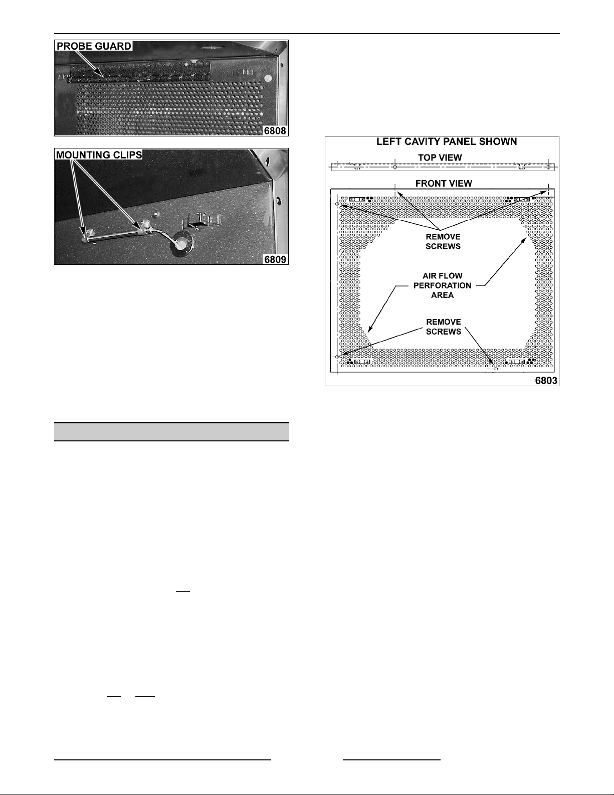
3. Remove the racks and ri ght rack support.
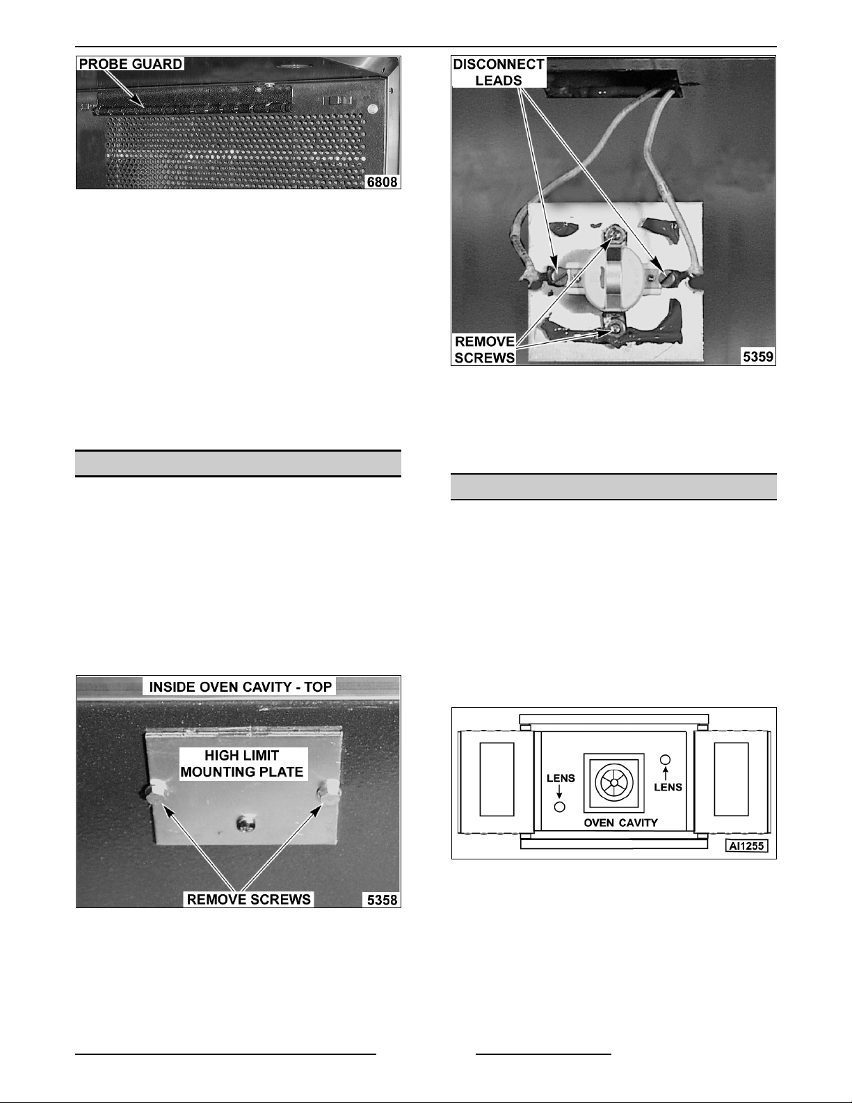
4. Remove the probe guard or mounting clips.
DISCONNECT THE ELECTRICAL
If right side panel is not accessible, t his
F25105 (Decem ber 2001) Page 8 of 60
Page 9
FULL SIZE ELECTRIC CONVECTION OVEN - REMOVAL AND REPLACEMENT OF PARTS
5. Remove probe by pushing it through the oven
wall and int o the control panel area.
A. Measure the current draw of the heating
element s as outlined under "HEAT ING
ELEMENT TEST" in "SERVICE
PROCEDURES AND ADJUSTMENTS".
4. From inside the oven cavity, remove the
perforat ed panel from the same side of the
element being replaced.
NOTE:
line up straight with the oven cavity outer shell,
therefor e the probe must be removed at an angle.
6. Reverse the procedure to install the
7. Adjust the temperature control as outlined
The hole in the oven cavity wall does not
replacement probe.
under "SOLID STATE TEMP E RA TURE
CONTROL CALI B RA TION" in " S E RV ICE
PROCEDURES AND ADJUSTMENTS".
HEATING ELEMENTS
WARNING:
POWER TO T HE MACHINE AT THE MAIN
CIRCUIT BO X. P LA CE A TAG ON THE CI RCUIT
BOX INDICATING THE CIRCUIT IS BEING
SERVICED.
NOTE:
the top cavity panel will have 3/4" square holes for
easier element removal. Ovens m anufactured prior
to this date have 1/2" r ound holes that sometimes
make it difficult to remove elements thru the cavity.
A serial number cut off will not
the procedures f or element remov al as outlined
below.
DISCONNECT THE ELECTRICAL
Starti ng wi th production in October, 2001,
be available. Follow
A. If r emov ing the right side panel, also
remove the probe guard or mounting clips.
B. Run the probe wire t hr u the panel opening
before l ifting panel out.
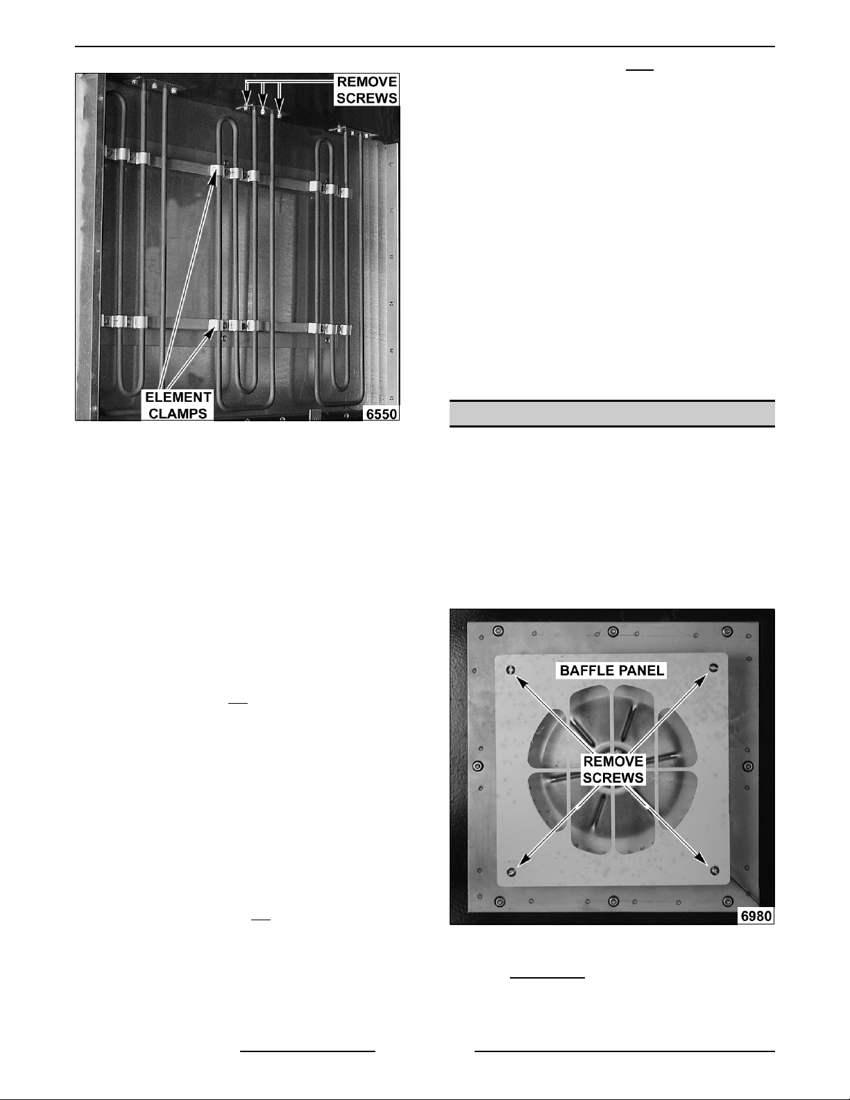
5. From t he element being replaced, r emov e the
hold down clam ps, the mounti ng br ac k et
screws at the top, then remove the element .
Front Access
1. Remove the oven racks and rack supports.
2. Remove the "top" door seal from the oven.
3. Determine if the heating element to replace is
on the left
element locations from front to back are: Right
side - R1, R2 & R3; Left side - R4, R5 & R6.
or right si de in the oven cavity. The
F25105 (Decem ber 2001)Page 9 of 60
Page 10
FULL SIZE ELECTRIC CONVECTION OVEN - REMOVAL AND REPLACEMENT OF PARTS
LEFT SIDE ELEMENTS SHOWN
NOTE:
which may still hold the element after the screws are
removed. Also, in some cases, the ri ng terminal
connected to the element may interfere with easy
removal. I f access to the l eft side panel and/or the
top panel is available, see "ALTERNATE ACCESS".
6. Disconnect the lead wires from the elem ent.
7. Clean RTV residue from the mati ng surface
The mounting bracket i s sealed with RTV
inside the oven, apply new hi gh temperature
RTV to the heat ing element mounti ng bracket
and rever se proc edur e to install .
3. If t he element is on the right
A. Remove the top panel and pull back the
insulation to expose the el ement
terminals.
B. Remove the lead wires from the element
being replaced.
4. From t he same element, remove the two
clamps holding the element vertical, the
screw’s securing mounting brac k et at the top,
and then remove the el ement.
NOTE:
which may still hold the element after the screws are
removed.
5. Clean RTV residue from the mati ng surface
6. Check for proper operation.
The mounting bracket i s sealed with RTV
inside the oven, apply new hi gh temperature
RTV to the heat ing element mounti ng bracket
and rever se proc edur e to install .
side:
BLOWER AND MOTOR
WARNING:
POWER TO T HE MACHINE AT THE MAIN
CIRCUIT BO X. P LA CE A TAG ON THE CI RCUIT
BOX INDICATING THE CIRCUIT IS BEING
SERVICED.
1. Take out the racks and rack supports.
2. Remove screws securing baffle panel and
remove the panel.
DISCONNECT THE ELECTRICAL
8. Check for proper operation.
Alternate Access
If t he heating element is not
inside the oven cavity, and ac cess to the left side
panel and/or the top panel is available, this al ternate
removal m ethod may be used.
NOTE:
being serv iced and the heating element to replace is
on the right side, the ovens must be unstacked to
access the heating el ement terminals through the
top. Once unstacked, fol low the removal procedur e
below.
1. Perform steps 1 thru 4 under "FRONT
2. If t he element is on the left
On stacked ovens, if the bottom oven is
ACCESS".
A. Remove the left side panel and pull back
the insulation at the top t o expose the
element terminals.
B. Remove the lead wires from the element
being replaced. Proceed to step 4.
removing easily from
side:
3. If replacing:
A. Blower Only
blower hub and using a bearing puller,
remove blower from motor shaft.
- Loosen set screws on
F25105 (Decem ber 2001) Page 10 of 60
Page 11
FULL SIZE ELECTRIC CONVECTION OVEN - REMOVAL AND REPLACEMENT OF PARTS
1) Reverse procedure to install and
adjust blower position as outlined
under "BLOWER ADJUST MENT" in
"SERVICE PROCEDURES AND
ADJUSTMENTS".
B. Motor
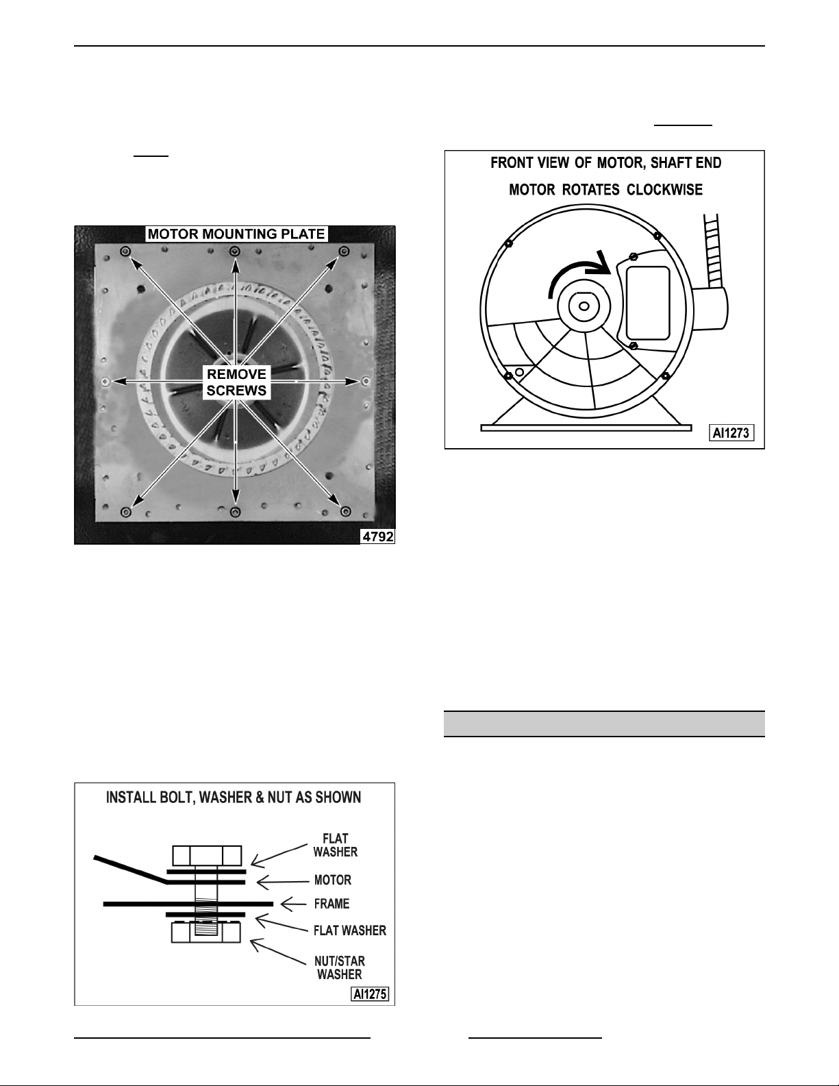
4. Remove the nuts that secure the motor
mounti ng plate to the rear wall.
- perform step 3A and continue
procedure.
10. Reconnect lead wires at the motor, replace
conduit and j unction box cover.
NOTE:
schematic. The motor must rotate clockwise
viewed from t he shaft end.
Check data plat e on motor for wiring
when
5. Place a piece of cardboard on the bottom of
the ov en c avity to protect its surface from any
damage during motor assembl y r emov al.
6. Pull t he motor assembl y into the oven cavity
and place it on the cardboard.
7. Remove the junct ion box cover f r om the motor,
disconnect l ead wir es and remove the conduit.
8. Remove motor mounting bolts and flat washers
then lift the motor f r om the mounting plate.
9. Position the replacem ent motor on t he motor
mounti ng plate and install mount ing bolts and
washers.
Hand tighten mounting bolts only
11. Slide blower onto motor shaft until hub is flush
with end of shaft then ti ghten set screws.
12. Adjust motor position until blower is parallel to
motor mounting pl ate as outlined under
"BLOWER ADJUSTMENT" in "SERVICE
PROCEDURES AND ADJUSTMENTS".
13. Position motor mounting pl ate on the rear wall
and secure with nuts and washers.
14. Replace t he baffle panel.
15. Remove cardboard from t he bottom of the
oven cavity.
16. Check oven for pr oper operation then replace
rack guides and racks.
DOOR SWITCH
.
WARNING:
POWER TO T HE MACHINE AT THE MAIN
CIRCUIT BO X. P LA CE A TAG ON THE CI RCUIT
BOX INDICATING THE CIRCUIT IS BEING
SERVICED.
1. Remove the top front cover as outlined under
"COVERS AND PANELS".
DISCONNECT THE ELECTRICAL
2. Disconnect the lead wires to the door switch.
3. Remove the switch.
F25105 (Decem ber 2001)Page 11 of 60
Page 12
FULL SIZE ELECTRIC CONVECTION OVEN - REMOVAL AND REPLACEMENT OF PARTS
4. Reverse proc edur e to install the replacem ent
switch and check for proper adjustment as
outlined under "DOOR SWITCH
ADJUSTMENT " in "SERVICE P ROCEDURES
AND ADJUSTMENTS".
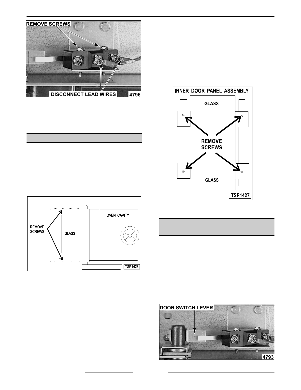
DOOR WINDOW
1) Lift out the inner door panel and
window assembly.
2) If replaci ng window on the right door,
remove the screws along the insi de
edge (if applicable) of the door then
remove the inner door panel and
window assembly.
4. Remove the screws securing the window “tabs”
to the door brack et and lift the window
assembly out from t he door frame.
WARNING:
POWER TO T HE MACHINE AT THE MAIN
CIRCUIT BO X. P LA CE A TAG ON THE CI RCUIT
BOX INDICATING THE CIRCUIT IS BEING
SERVICED.
1. Remove the screws at the top and bott om of
door.
2. Independent doors:
A. Remove the door handl e then remove the
B. Lift out the i nner door panel and window
DISCONNECT THE ELECTRICAL
outer door panel.
assembly.
5. Reverse proc edur e to install the replacem ent
window.
OVEN DOORS AND BEARINGS
(INDEPENDENT DOORS)
WARNING:
POWER TO T HE MACHINE AT THE MAIN
CIRCUIT BO X. P LA CE A TAG ON THE CI RCUIT
BOX INDICATING THE CIRCUIT IS BEING
SERVICED.
1. Remove the top front cover and bottom front
cover as outlined under "CO V E RS A ND
PANELS".
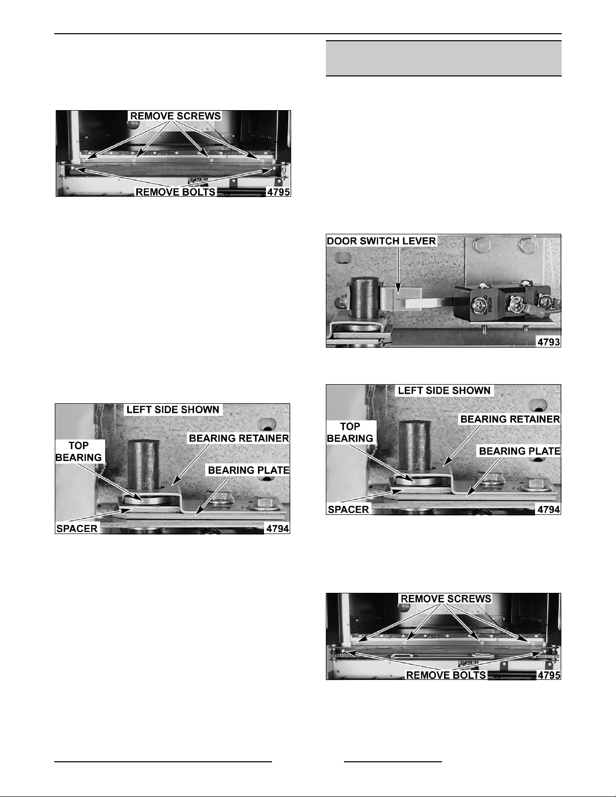
2. Remove the door switch lever.
DISCONNECT THE ELECTRICAL
NOTE:
the inside edge of the door.
3. Simultaneous doors:
A. If r eplacing window on the left door,
F25105 (Decem ber 2001) Page 12 of 60
Left door only - rem ove door seal from
remove the handle from t he front of the
door then remove door seal from the
inside edge of the door.
Page 13
FULL SIZE ELECTRIC CONVECTION OVEN - REMOVAL AND REPLACEMENT OF PARTS
3. Remove the lower door seal strip to expose the
mounti ng scr ews of the door assembly.
4. Remove the two (2) lower sill bolts by the lower
door shaft and the four (4) counter-sunk screws
from the lower sill.
NOTE:
down once the last screw is removed. If removing
door assembly with- out assistance, use caution.
5. Tilt the top of the door slightly forward and l ift
6. Lay the door f lat to prevent dam age.
7. The top and bottom bearings are now
The door assembly is heavy and will drop
the door up until the bottom of the door shaft
clears the openi ng in the sill.
accessible for inspection and/or replacement if
needed.
OVEN DOORS
(SIMULTANEOUS DOORS)
WARNING:
POWER TO T HE MACHINE AT THE MAIN
CIRCUIT BO X. P LA CE A TAG ON THE CI RCUIT
BOX INDICATING THE CIRCUIT IS BEING
SERVICED.
Assembly Removal
1. Remove the top front cover and bottom front
cover as outlined under "CO V E RS A ND
PANELS".
2. Remove the door switch lever.
DISCONNECT THE ELECTRICAL
A. If bear ings are ok, proceed to step 8.
B. If r eplacing the top bearing, remove the
top bearing retainer and top bearing.
C. If replacing the bottom bearing, remove it
from the door shaft or the lower sill
opening.
8. Reverse proc edur e to install door assembly
and check for proper adjustment as outlined
under "DOOR ADJ US TMENT" and "DO OR
SWIT CH ADJUSTMENT" in "SERVICE
PROCEDURES AND ADJUSTMENTS".
3. Remove the top beari ng r etainers and top
bearings.
4. Remove the lower door seal strip to expose the
mounti ng scr ews of the door assembly.
A. Remove the two (2) lower sill bolts by the
lower door shaft and the four (4)
counter-sunk screws from the lower sill.
NOTE:
down once the last screw is removed. If removing
door assembly with- out assistance, use caution.
The door assembly is heavy and will drop
F25105 (Decem ber 2001)Page 13 of 60
Page 14
FULL SIZE ELECTRIC CONVECTION OVEN - REMOVAL AND REPLACEMENT OF PARTS
5. Lift up on the door assembly and swing the
right side out then move the assembly to the
left to clear t he slots in the upper door sill.
6. Lay the door assembly on a flat c ushi oned
surface for disassembly.
7. Reverse proc edur e to install door assembly
and check for proper adjustment as outlined
under "DOOR ADJ US TMENT", "DOOR CHAIN
ADJUSTMENT (SIMULTANEOUS DOORS)"
and "DOOR SWITCH A DJ US TMENT" i n
"SERVICE PROCEDURES AND
ADJUSTMENTS".
Disassembly
1. Remove the door assembly as outlined in
"OVEN DOO R S ( S IMULTANEOUS) " under
"ASSEMBLY REMOVAL".
2. Remove the door chain by loosening one of the
turnbuckles.
3. Loosen the set screw on the sprocket of door
being replaced.
4. Drive out the spirol pin fr om the sprocket of
door being repl ac ed.
DOOR CATCH ROLLER
ASSEMBLY
(INDEPENDENT DOORS)
WARNING:
POWER TO T HE MACHINE AT THE MAIN
CIRCUIT BO X. P LA CE A TAG ON THE CI RCUIT
BOX INDICATING THE CIRCUIT IS BEING
SERVICED.
1. Remove the top front cover as outlined under
“COVERS AND PANELS”.
2. Remove the catch roller assembly .
DISCONNECT THE ELECTRICAL
5. Remove the door f r om lower sill bearings and
sprocket.
A. Door assembly par ts are now accessible
for i nspection and/or replacement if
necessary.
6. Reverse proc edur e to re-assemble the door
assembly parts and check for proper
adjustment as outlined under "DO OR CHAIN
ADJUSTMENT (SIMULTANEOUS DOORS)" in
"SERVICE PROCEDURES AND
ADJUSTMENTS".
3. Reverse proc edur e to install .
4. Adjust the catch roller as outlined under
“DOOR CATCH (ROLLER) ADJUSTME NT
(INDEPENDENT DOORS)” in “SERVICE
PROCEDURES AND ADJUSTMENTS”.
MECHANICAL (KX)
THERMOSTAT
WARNING:
POWER TO T HE MACHINE AT THE MAIN
CIRCUIT BO X. P LA CE A TAG ON THE CI RCUIT
BOX INDICATING THE CIRCUIT IS BEING
SERVICED.
1. Remove the racks and ri ght rack support.
2. Remove the thermostat knob and mount ing
screws from the c ontrol panel and t hen r emov e
the control panel.
3. Remove the probe guard from the oven cavity
wall.
DISCONNECT THE ELECTRICAL
F25105 (Decem ber 2001) Page 14 of 60
Page 15
FULL SIZE ELECTRIC CONVECTION OVEN - REMOVAL AND REPLACEMENT OF PARTS
NOTE:
should not ext end beyond the guard.
4. Remove the thermostat bulb from the oven
NOTE:
line up straight with the oven cavity outer shell,
therefor e the probe must be removed at an angle.
5. Reverse the procedure to install.
6. Adjust the thermostat as outl ined under
When installing probe guard, the probe
cavity by pushing it through the oven wall and
into the control panel ar ea.
The hole in the oven cavity wall does not
"MECHANICAL (K X) T HE RM OSTAT
CALIBRATI ON " in "SERVICE PROCEDURES
AND ADJUSTMENTS".
HIGH LIMIT THERMOSTAT
WARNING:
POWER TO T HE MACHINE AT THE MAIN
CIRCUIT BO X. P LA CE A TAG ON THE CI RCUIT
BOX INDICATING THE CIRCUIT IS BEING
SERVICED.
1. Take out rack s from the oven.
DISCONNECT THE ELECTRICAL
NOTE:
and mati ng surfaces inside the oven cavity and
apply new high temperature RTV seal er before
installing.
4. Reverse proc edur e to install .
Remove the old RTV seal er from the cover
INTERIOR LIGHTS
WARNING:
POWER TO T HE MACHINE AT THE MAIN
CIRCUIT BO X. P LA CE A TAG ON THE CI RCUIT
BOX INDICATING THE CIRCUIT IS BEING
SERVICED.
DISCONNECT THE ELECTRICAL
2. Remove the high l imit thermostat
cover /mounti ng plate fr om inside t he oven
cavity at the top.
3. Disconnect lead wi r es from hi gh limit
thermostat then remove high limit therm ostat
from cover /mounti ng plate.
Lamp
1. Remove the racks.
2. Unscrew the glass lens for the light bei ng
replaced then unscrew the bulb.
3. Replace bulb t hen reverse the pr oc edur e to
install.
Lamp Assembly
1. Remove the lens and bulb.
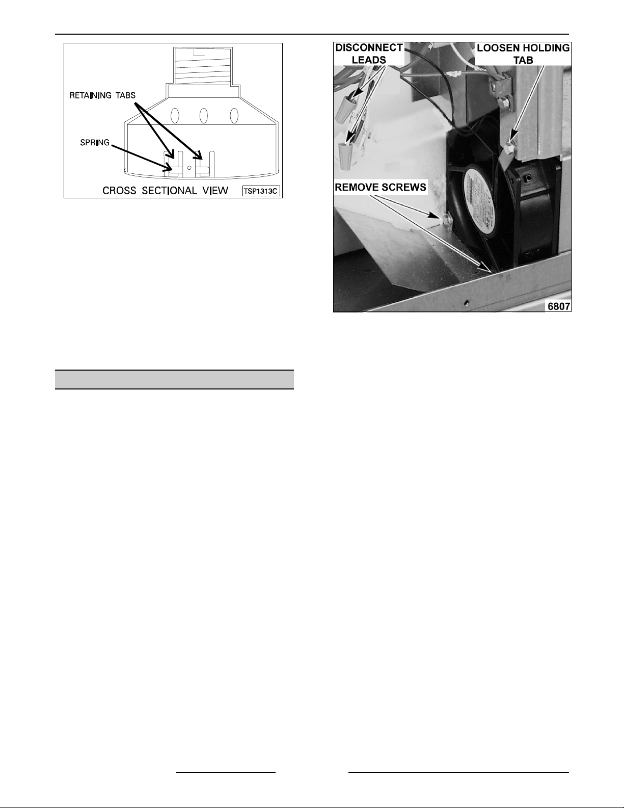
2. Remove the springs from the ret aining tabs (2
places) on the socket.
F25105 (Decem ber 2001)Page 15 of 60
Page 16
FULL SIZE ELECTRIC CONVECTION OVEN - REMOVAL AND REPLACEMENT OF PARTS
3. Depress the retaini ng tabs and pull the socket
out from the oven, far enough to disconnect the
lead wires.
4. Remove the socket from the oven.
5. Attach the lead wires to the repl ac ement
socket.
6. Insert the socket into the hole in the oven and
push until the sock et is held in place by the
retaini ng tabs.
7. Install the light bulb and lens.
8. Check for proper operation.
COOLING FAN
WARNING:
POWER TO T HE MACHINE AT THE MAIN
CIRCUIT BO X. P LA CE A TAG ON THE CI RCUIT
BOX INDICATING THE CIRCUIT IS BEING
SERVICED.
1. Remove the right side panel as outli ned under
"COVERS AND PANELS".
DISCONNECT THE ELECTRICAL
4. Reverse the procedure to install the
replacement fan and check for proper
operation.
NOTE:
from outside the rear of the oven and blown into t he
control ar ea. The arrow on the fan body indicates
“air f low” directi on and shoul d be pointing toward the
controls.
NOTE:
air tube and the oven bott om.
NOTE:
at approximatel y 30 degrees to properly direct the
air f low.
The fan must be installed so air is pulled
Ensure fan is seated “squarely” against the
The air deflector should be angled upwards
NOTE:
component can be servic ed by r emov ing the control
panel as outli ned under "COVERS AND PA NE LS " .
2. Disconnect the lead wires to the f an motor by
3. Remove the screws securing the air deflect or
F25105 (Decem ber 2001) Page 16 of 60
If right side panel is not accessible, t his
removing wire nut s.
to the f an then loosen the tab screw holdi ng the
fan to t he c omponent panel. Rotate the tab so
that the fan will clear and remove the fan.
Page 17
FULL SIZE ELECTRIC CONVECTION OVENS - SERVICE PROCEDURES AND ADJUSTMENTS
SERVICE PROCEDURES AND ADJUSTMENTS
WARNING:
CERTAIN PROCEDURES IN THIS SECTION REQUIRE ELECTRICAL TEST OR
MEASUREMENTS WHILE POWER IS APPLIED TO THE MACHINE. EXERCISE EXTREME CAUTION AT ALL
TIMES. IF TEST POI NT S ARE NOT EASI LY ACCESSIBLE, DISCONNECT POWER, ATTACH TEST
EQUIPMENT AND REAPPLY POWER TO TEST .
SOLID STATE TEMPERATURE
CONTROL CALIBRATION
1. Place a thermocouple in the geometr ic center
of the oven cavity.
2. Set the power switch to O N.
3. Set the temperature control dial to 350 °F.
4. Allow the oven temperature to stabilize
(normally 3 cycles).
5. Record the temperature at which the Heat lamp
goes OFF and comes ON for at least two
complete heat ing cycles.
6. Calculat e the differenti al by subtracting the
temperat ure indicat ed when the lamp goes out
from the temper ature indic ated when the lamp
comes on.
A. If the average temperature is 10 °F or
, from the dial setting, t he thermostat
less
is properly c alibrated.
B. If the average temperature is more
than
10 °F from the dial setting, the therm ostat
calibration must
be adjusted.
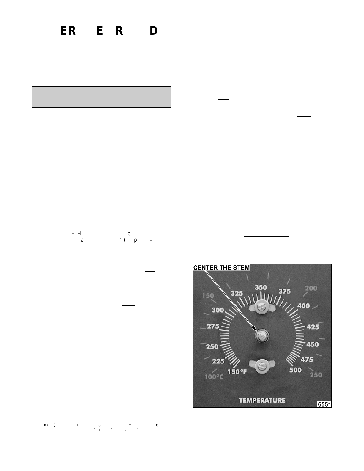
1) Loosen the tem per ature control k nob
set screw and remove the knob fr om
the stem.
2) Loosen temperature control mounting
screws only enough to rotate t he
control.
a. Place thumb and forefinger on
the head of t he mounting
screws, apply pressure and
slightly rotate the screw heads
(body of control) i n the slot.
Rotate clockwise
to increase
temperat ure and
DifferentialHeat lamp OFFHeat lamp ON
Example
: 360((
lamp off
)340((
lamp on
)20
A. The differential calculated should be less
than 20 °F.
counterclockwise
(
b. Center the stem in the opening
and re-tighten the temper ature
control mounting screws.
to decrease.
1) If the differential is 20 °F or less
, the
temperat ure control circuit is
functioning properly.
a. Proceed to step 7.
2) If the differential is more
than 20 °F:
a. Check the temperature probe as
outlined under "TEMPERAT URE
PROBE TEST (SOLID STATE
CONTROL)".
b. If t he pr obe is functioning
properly t hen temperature
control is malfunctioning.
a) Install a replacement
temperat ure control and
check calibration.
7. Calculat e the average temperatur e by adding
the temper ature indic ated when the lamp goes
out to the temperature i ndicated when the lamp
comes on and dividi ng this answer by 2.
[
Temp.(lamp off
)
Example
Temp.(lamp on
: 360
340(÷ 2350
(
)] ÷ 2
Average Temp
(
.
c. Replace knob and re-tighten set
screw .
F25105 (Decem ber 2001)Page 17 of 60
Page 18
FULL SIZE ELECTRIC CONVECTION OVENS - SERVICE PROCEDURES AND ADJUSTMENTS
d. Rotate the knob t o the lowest
temperat ure setting then back to
350°F.
e. Repeat the average temper ature
calculation in step 7.
NOTE:
Allow the oven to cycle
at least two times between
adjustment s before perf or ming
the calculation.
a) If the av erage temperat ur e
still differs more
than 10 °F
from the dial setting, adjust
the therm ost at calibration
until the average
temperat ure is within
tolerance.
C. If the above adjustment cannot be
obtained:
1) Turn the power switch O FF.
WARNING:
DISCONNECT THE ELECTRICAL
POWER TO T HE MACHINE AT THE MAIN
CIRCUIT BO X. P LA CE A TAG ON THE CI RCUIT
BOX INDICATING THE CIRCUIT IS BEING
SERVICED.
2) If the differential is more
than 30 (F,
the therm ost at is malfuncti oning.
a. Install a replacement thermostat
and check calibration.
7. Calculat e the average temperatur e by adding
the temper ature indic ated when the heat lamp
goes out to the temperature indicated when the
heat lam p c omes on and dividing t his answer
by 2.
[
Temp.(lamp off
)
Example
Temp.(lamp on
: 360
340(÷ 2350
(
)] ÷ 2
Average Temp
(
A. If the average temperature is 15 (F or less
from the dial setting, the t hermostat i s
properly calibrated.
B. If the average temperature is more
than
15 (F of t he dial setti ng, the thermostat
calibration must
be adjusted.
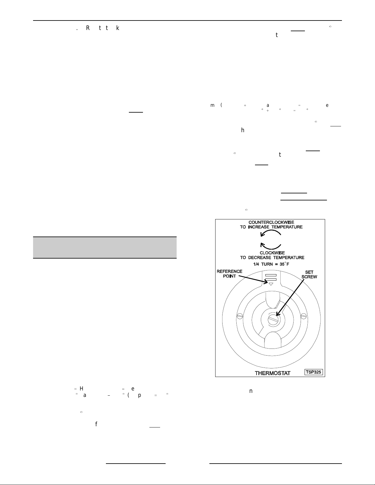
1) Remove the thermostat knob.
2) Hold the thermostat shaft and turn the
inner set screw clockwise
temperat ure or countercl oc k wise
to decrease
to
increase temperature (¼ turn =
35(F).
.
2) Replace the temperat ur e c ontrol and
check calibration.
MECHANICAL (KX)
THERMOSTAT CALIBRATION
1. Place a thermocouple in the geometr ic center
of the oven cavity.
2. Set the power switch to O N.
3. Set the thermostat dial to 350 °F.
4. Allow the oven temperature to stabilize
(normally 3 cycles).
5. Record the temperature when the thermostat
cycles OFF and ON for at least three complete
cycles.
6. Calculat e the differenti al by subtracting the
temperat ure indicat ed when heat lamp goes out
from temperat ure indicat ed when heat lamp
comes on.
DifferentialHeat lamp OFFHeat lamp ON
Example
: 360((
A. The differential calculated should be less
than 30(F.
1) If the differential is 30 °F or less
lamp off
)340((
lamp on
)20
, the
thermostat is funct ioning properl y .
a. Proceed to step 7.
(
8. Replace the knob and verify the setting is stil l
at 350°F.
9. Repeat step 7 until the av er age temperatur e is
within tolerance.
NOTE:
Allow the oven to cycle at least two times
between adjustment s before perfor ming the
calculation.
F25105 (Decem ber 2001) Page 18 of 60
Page 19

FULL SIZE ELECTRIC CONVECTION OVENS - SERVICE PROCEDURES AND ADJUSTMENTS
A. After the final adjustment is made and the
average temperature is within tolerance,
remove the knob and apply a nonpermanent t ype sealer around the head of
the set screw.
10. If the abov e adjustment cannot be obtained:
A. Turn the power switch O FF.
WARNING:
POWER TO T HE MACHINE AT THE MAIN
CIRCUIT BO X. P LA CE A TAG ON THE CI RCUIT
BOX INDICATING THE CIRCUIT IS BEING
SERVICED.
B. Install a replacement therm ostat and
DISCONNECT THE ELECTRICAL
check calibration.
SOLID STATE TEMPERATURE
CONTROL TEST
1. Remove the right side panel as outli ned under
"COVERS AND PANELS" in "REMOVAL AND
REPLACEMENT OF PARTS".
NOTE:
component can be servic ed by r emov ing the control
panel as outli ned under "COVERS AND PA NE LS " .
2. Place a thermocouple in the geometr ic center
NOTE:
3. Set the temperature control to the maximum
4. Check machine data plate for correct voltage to
5. Turn the power switch to O N.
If right side panel is not accessible, t his
of the oven cavity.
Ov en temperature must
setting.
oven. Refer to di agr am below for pr oper
terminal locations and voltages before
checking the c ontrol. Use the cor r ec t terminals
for the c orresponding v oltage.
be below 450°.
A. If c orrect, proceed to step 7.
B. If incorrect, problem is not
temperat ure control. S ee
"TROUBLESHOOTING".
7. Check relay volt ages on t he boar d:
A. For 208-240VA C c ontrols - check across
terminals 7 & 10 for input to the internal
relay and 6 & 10 for output from the
internal relay.
1) If input voltage t o the internal relay is
correct, pr oc eed to step 8. If input
voltage to the i nternal relay is not
present, problem is not with the
temperat ure control. S ee
"TROUBLESHOOTING".
2) If output voltage from the internal
relay is cor r ec t proceed to step 8. If
output voltage from the internal relay
correct, c hec k temperature
is not
probe as outlined under
"TEMPERATURE PROBE TEST
(SOLID STATE CONTROL)".
8. Set the temperature control to the minimum
setting.
NOTE:
9. Check for zero (0) volts AC across terminals 6
WARNING:
POWER TO T HE MACHINE AT THE MAIN
CIRCUIT BO X. P LA CE A TAG ON THE CI RCUIT
BOX INDICATING THE CIRCUIT IS BEING
SERVICED.
Ov en temperature must
& 10 (208-240VAC) for no output from t he
internal relay.
A. If c orrect, temperature cont r ol is
functioning properly.
B. If incorrect, check tem per ature probe as
outlined under "TEMPERAT URE P ROBE
TEST (SOLID STATE CONTROL)".
1) If temperature probe is ok:
a. Turn the power switch OF F.
DISCONNECT THE ELECTRICAL
with the
be above 300°F.
6. Check for proper voltage across terminals 8 &
10 (208-240VAC) for power to the control.
b. Replace the temperature control
and check calibration as outlined
under "SOLID S TATE
TEMPERAT URE CONTROL
CALIBRATION".
F25105 (Decem ber 2001)Page 19 of 60
Page 20

FULL SIZE ELECTRIC CONVECTION OVENS - SERVICE PROCEDURES AND ADJUSTMENTS
TEMPERATURE PROBE TEST
(SOLID STATE CONTROL)
WARNING:
POWER TO T HE MACHINE AT THE MAIN
CIRCUIT BO X. P LA CE A TAG ON THE CI RCUIT
BOX INDICATING THE CIRCUIT IS BEING
SERVICED.
NOTE:
with the Solid State Temperature cont rol is an RTD
(resistance temperature detector) of t he Thermistor
type. As temperature inc r eases the resistanc e value
decreases.
1. Remove the right side panel as outli ned under
"COVERS AND PANELS" in "REMOVAL AND
REPLACEMENT OF PARTS".
NOTE:
component can be servic ed by r emov ing the control
panel as outli ned under "COVERS AND PA NE LS " .
2. Place a shielded thermocouple in the geometric
center of the oven cavity and determine the
temperat ure in the oven cav ity.
3. Remove the probe lead wir es from the sol id
state temperature control.
4. Test the probe with an ohmmeter .
A. If the measured resistance values are
B. If the measured resistance values are
5. Reverse proc edur e to install .
TEMP (°F) OHMS* TEMP (°F) OHMS*
(*) Resistance in ohms ± 10%
DISCONNECT THE ELECTRICAL
The temper ature probe used in conjunc tion
If right side panel is not accessible, t his
inside the given tolerance then the pr obe
is funct ioning properly.
outside the given tolerance then repl ac e
the probe and retest.
1) Check oven for pr oper oper ation.
77 90,000 360 822
240 4,077 380 656
260 3,016 400 529
280 2,266 425 424
300 1,726 450 334
320 1,332 475 266
340 1,041
HEATING ELEMENT TEST
WARNING:
POW E R TO BE APPLIED TO THE UNI T DURING
THE TEST. USE EXTREME CAUTION AT ALL
TIMES.
1. Turn the power switch ON and set t he oven
temperat ure control t o the highest setting.
2. Measure the voltage at the heating element
terminals and verify it against t he data plate
voltage.
A. If voltage is incorrec t
B. If voltage is correct
NOTE:
resistance check when a clamp on type am p
meter is available.
C. If unable to chec k current draw, a
3. Check for proper operation.
VOLTAGE
208
240
480
NOTES:
THE FOLLOWI NG ST EPS REQUIRE
, find the source of
the problem.
, check curr ent draw
(amps) through the heating element lead
wires.
This method is preferr ed over a
1) If current draw is correc t then heating
element is functioning properl y .
table below for proper values.
2) If current draw is not
power switch OFF and
the electrical supply to the oven.
a. Replace heati ng element t hen
proceed to step 3.
resistance check may
malfunctioning element.
1) Turn the power switch O FF and
disconnect the electrical supply to
the oven.
2) Remove the l ead wi r es from the
heating element and check r esi stanc e
(ohms).
values.
KW PER
ELEMENT
1. Values in the table are nominal.
Tolerance is +5/-10%.
2. Voltage values are @ 60HZ.
3. Resistance values (ohms) are @
room temperature.
See table below for proper
AMPS PER
ELEMENT
1 PH 3 PH
2603521
2523328
2 15 4 111
correct, turn the
disconnect
indicate a
OHMS PER
LEAD
See
ELEMENT
F25105 (Decem ber 2001) Page 20 of 60
Page 21

FULL SIZE ELECTRIC CONVECTION OVENS - SERVICE PROCEDURES AND ADJUSTMENTS
BLOWER ADJUSTMENT
WARNING:
PLACE A TAG ON THE CIRCUIT B OX INDICATING THE CIRCUIT I S B E ING SERVICED.
1. Remove the blower motor and mounting assembly by following steps 1 through 7 as outlined under
"BLOWER AND MOTOR" in "REMOVAL AND REPLACEMENT OF PARTS".
2. Loosen the motor mounting bolts.
3. Adjust the motor position until the blower is parall el to and 1/4 inc h away from the motor m ounting plate.
Check for squareness of the blower to the m otor mounting plate at t he top, bottom, left and right of the
blower.
A. If the blower is square then ti ghten motor mounting bol ts and proceed to step 4.
B. If the blower is not square continue adjusting until proper spacing is achieved then tight en motor
NOTE:
DISCONNECT THE ELECTRICAL POWE R TO THE MACHINE A T THE MAIN CI RCUIT BOX.
mounti ng bolts.
If necessary, place shims between motor and frame.
4. Reverse the procedure to install.
F25105 (Decem ber 2001)Page 21 of 60
Page 22

FULL SIZE ELECTRIC CONVECTION OVENS - SERVICE PROCEDURES AND ADJUSTMENTS
DOOR ADJUSTMENT
1. Check the doors to make sure they have an
equal gap between them and that the vertical
edge of the door is parallel to the vertical door
seal. If the doors are not positioned in thi s
manner, adjust the doors as described.
DOOR CATCH ROLLER
ADJUSTMENT
(INDEPENDENT DOORS)
WARNING:
POWER TO T HE MACHINE AT THE MAIN
CIRCUIT BO X. P LA CE A TAG ON THE CI RCUIT
BOX INDICATING THE CIRCUIT IS BEING
SERVICED.
1. Remove the top front cover as outline under
"COVERS AND PANELS" in "REMOVAL AND
REPLACEMENT OF PARTS".
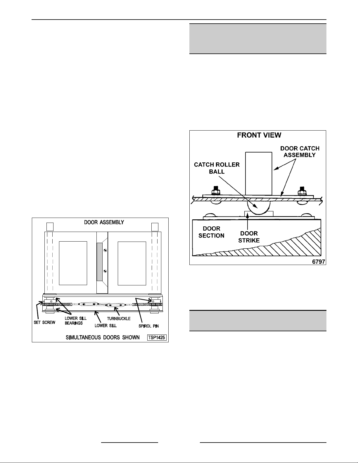
2. Open the doors and inspect the door strike for
proper shape.
DISCONNECT THE ELECTRICAL
2. Remove the top front cover.
3. Loosen the screws that secure the upper door
bearings and relat ed har dware, just enough to
allow door m ovem ent.
4. Move the door until proper alignment is
achieved then tighten the screws on the upper
door bearing hardware.
5. Repeat step 3 and 4 on the opposite door , if
necessary.
A. Replace i f bent and adjust as out lined in
this procedure.
3. Open and close the doors several times while
observi ng the catch rol ler operation.
A. Replace i f malfunctioning and adjust as
outlined in this procedure.
NOTE
: Shims may be requir ed under the
door strike t o r aise it, before the proper
door tension adjustment can be set.
4. Apply lubricant around t he spring. See
“LUBRICATION” under “GENERAL”.
5. Close the doors and check them for pr oper
alignment.
A. Doors should be centered and parallel at
the top and bottom, in t he oven cavity
opening. See "DOOR ADJUSTME NT".
F25105 (Decem ber 2001) Page 22 of 60
Page 23

FULL SIZE ELECTRIC CONVECTION OVENS - SERVICE PROCEDURES AND ADJUSTMENTS
6. With the doors closed, observe the posit ion of
the catch roller "bal l" in rel ation to the door
strike.
A. Ensure the catc h r oller "bal l" is centered
(lef t to right) to the door stri k e.
1) Adjust alignment, if necessary.
B. Open the right side door and view the left
side door catch roller and stri k e. Ensure
the door catch r oller "bal l" is resting upon
the angular surface of the door strike.
Repeat on the opposite door.
1) If adjustment is necessary, loosen the
mounti ng scr ews then sli de the door
strike from "front to back " until the
roller r ests upon the angular surface
of the door strike. Tighten screws and
check operation.
2) If proper adjustment cannot be
achieved, add shims beneath the
door strike. Repeat step 6 thru this
step. DO NOT B E ND THE DOOR
STRIKE.
7. Each ov en door should open with a forc e of 8
to 25 pounds when pulled at the handle. See
"TOOLS " under " GENERAL".
DOOR SWITCH ADJUSTMENT
WARNING:
POWER TO T HE MACHINE AT THE MAIN
CIRCUIT BO X. P LA CE A TAG ON THE CI RCUIT
BOX INDICATING THE CIRCUIT IS BEING
SERVICED.
1. Remove the top front cover as outlined under
"COVERS AND PANELS" in "REMOVAL AND
REPLACEMENT OF PARTS".
2. Door operation:
A. Independent doors
B. Simultaneous doors
3. If adjustment i s necessary, bend the switch
actuator to obtain the proper setting.
DISCONNECT THE ELECTRICAL
- The switch actuator
should be operated by the switc h lever
when the right door is between 1" and 1 ½
" from being cl osed.
- The switch actuator
should be operated by the switc h lever
when the right door is ½ " from being
closed.
A. Adjust catch roller tension as follows:
1) Turn the set screw inside the catch
assembly housing clockwise
increase tension on t he c atch roller
and counterclockwise
tension on the catch roller.
: The amount of tension on the
NOTE
catch roller determines the opening force
of the door.
2) Continue adjustment until proper door
operation i s achieved.
to
to decrease
4. Install the top front cover .
5. Apply power to the oven and check for proper
operation.
DOOR CHAIN ADJUSTMENT
(SIMULTANEOUS DOORS)
Introduction
When the oven doors are in proper adjustment, as
the doors come t ogether, the ri ght door will lead the
left door in closing by about 1/4 inc h. The doors will
feel like they ar e self cl osi ng the last ½ inch of
travel.
Procedure
1. Remove the lower sill cover as outline under
"COVERS AND PANELS" in "REMOVAL AND
REPLACEMENT OF PARTS".
2. Close doors and check door chai n for f ac tory
setting.
F25105 (Decem ber 2001)Page 23 of 60
Page 24

FULL SIZE ELECTRIC CONVECTION OVENS - SERVICE PROCEDURES AND ADJUSTMENTS
A. Turnbuckles should be 5 to 5 ½ inches
apart.
B. Short eye bolt should be connected to the
end of the chain that goes to the front of
the sprocket.
C. 2 links of the c hain should not be engaged
at the rear of the sprocket.
D. Chain must be tight enough that the doors
move simul taneously when opened or
closed.
E. When the doors are opened, the
turnbuckles will move away from each
other.
F. The stop cable must be positioned where it
moves freely and does not get pinched.
3. Position door c hain assembly to factory sett ing
if the conditi ons in step 2 are not met .
B. If door s operate properly, c ontinue to step
7.
7. Install the lower front cover .
COMPUTER CONTROL
Operation
Refer to the Instructions Manual for specific
operating i nst r uc tions.
Setup mode
NOTE:
is configured to the factory settings which result in
the proper operation of the oven. If the CAL1
parameter is other than zero, determine if i t is still
needed before resetting to zero. S ee " COMPUTER
CONTROL TE M P E RA TURE CALIBRATION".
CAUTION: Ch anging t he C_F, InP 1, rL1 & rH1
parameters will default all
settings.
1. Use this key sequence to access the setup
Use the setup mode to verify
menus to the factory
mode.
that the cont r ol
4. If right door does not lead the left door in
closing:
A. Loosen locknuts on both turnbuckles.
B. Loosen left turnbuckl e.
C. Tighten right turnbuckle.
D. Tighten locknuts on both turnbuckles.
5. If t he r ight door leads the left door by more
than 3/8 inch:
A. Loosen locknuts on both turnbuckles.
B. Loosen right t ur nbuc k le.
C. Tighten left turnbuckle.
Up arrow; Rack 1; Temperature; Temperature;
Down arr ow; Rack 1
2. Once in the setup mode the displ ay will
alternate between the parameter and
programmed data.
• To change data to t he factory set ting, use
the arrow keys.
• To select the next parameter, press the
Rack 1 key.
• After the last Param eter and Data is
viewed, press the Rack 1 key a final ti me
to exi t the setup mode and return to
operations m ode. The current set point
temperature will be displayed.
• After 1 minute of no key activat ions, the
control will return to operation m ode.
3. Listed are the parameters and data you should
find.
D. Tighten locknuts on both turnbuckles.
6. Check door for proper operation.
NOTE:
the adjustment will not hold.
F25105 (Decem ber 2001) Page 24 of 60
The locknut s must be tight dur ing testing or
A. If door s do not c lose properly, repeat step
4, 5 and 6.
Page 25

FULL SIZE ELECTRIC CONVECTION OVENS - SERVICE PROCEDURES AND ADJUSTMENTS
ALTERNATI NG ON
MENU
DISPLAY
PARAMETER DATA
Celsius_Fahrenheit C_F F
Guard Band gb 4000
Temperature
Compensation
tcnP OFF
Input Type 1 InP1 J
Range Low 1 rL1 75
Range High 1 rH1 500
Hysteresis HYS1 3
Calibrat ion Offset CAL1 0
Exit Setup Mode and
return to Operation
Mode.
set point temperature i s
displayed or if cal l for
heat, dashes (----)
displayed.
Probe Test
If t he oven is not heating or displaying the proper
temperat ure, the temperature probe m ay be
malfunctioning. Determine if the probe is good or
causing the operational problem. Temporarily ,
disconnect the existing pr obe lead wires from the
computer control and connect the lead wires f r om a
known good "J" type thermocouple. S ec ure the
sensing end of the thermocouple near the probe.
Turn the power switch ON and set t he dial to 350°F.
If t he oven reaches the set tem perature and cycles
with the temporary thermocouple, t hen the existing
probe is malfunctioning. Repl ac e temperature pr obe
with the correc t part and check for proper operation.
Solid S t ate Relay Test
The solid stat e r elays "SSR1 or SSR2" suppl y power
to the blower motor "high" or "low" fan speed
terminals when the SSR is energiz ed by the output
voltage from the com puter.
To test soli d state relay "SSR1" (high fan speed),
the comput er control should be in the "Norm al
Cooking Mode". To test solid state r elay "SSR2"
(low fan speed), the computer c ontrol should be in
the "Cook & Hol d M ode" .
1. Remove the right side panel as outli ned under
"COVERS AND PANELS".
2. Turn the power switch ON.
A. If the blower motor c omes on, the SSR i s
functioning properly.
B. If the blower motor does not c ome on,
proceed to step 3.
3. Check for +5 VDC on the input si de of SSR
(terminals 3 & 4).
A. If +5 VDC is present, cont inue to step 4.
B. If no voltage is present, computer control
is not func tioning proper ly.
4. Check for proper input voltage on t he load side
of SSR t erminal 1 and the power connection on
the other side of the supply.
A. On 208 & 240 volt ovens, the supply
connection is on the terminal block ( L2 for
single phase, L3 for three phase).
The measured voltage shoul d be identical
to the supply.
B. On 480 volt ovens, the supply connec tion
is on the secondary side of the 480V
transformer, terminal X4 (wire # 79) .
The measured voltage shoul d be 240
volts.
5. If input v oltage is correc t on the load side of
SSR terminal 1, pr oc eed to step 6.
A. If input voltage is not
correct, find the
source of the pr oblem.
6. Check output voltage on the load side of S S R
terminal 2.
F25105 (Decem ber 2001)Page 25 of 60
Page 26

FULL SIZE ELECTRIC CONVECTION OVENS - SERVICE PROCEDURES AND ADJUSTMENTS
A. If voltage is correct, SSR is func tioning
properly.
B. If no voltage is present on the load si de of
SSR terminal 2, the SSR is not
properly.
7. Turn the power switch OF F.
WARNING:
POWER TO T HE MACHINE AT THE MAIN
CIRCUIT BO X. P LA CE A TAG ON THE CI RCUIT
BOX INDICATING THE CIRCUIT IS BEING
SERVICED.
8. Replace the SSR and check for pr oper
operation.
DISCONNECT THE ELECTRICAL
functioning
COMPUTER CONTROL
TEMPERATURE CALIBRATION
1. Place a thermocouple in the geometr ic center
of the oven cavity.
2. Turn the power switch ON.
A. If the set point temperature is 350°F,
proceed to step 4.
B. If the set point temperature is ot her than
350°F, proceed t o step 3 to change the
temperature.
3. Press the set key then temperature key t o enter
the temper ature set mode.
A. The display will alternate between the term
"StPt" ( set point) and the curr ent oven
temperat ure setting.
B. Press the up or down arrow keys to make
the proper select ion.
C. Press the set key again to save the
change and exit the temper ature set
mode.
4. Allow the oven temperature to stabilize
(normally 3 cycles).
5. Compare the controls set point temperature to
the therm ocouple meter reading when the heat
light goes out.
A. A tem perature v ariance mor e
indicat es an adjustment i s needed.
1) To make the adjustment, proceed to
step 6.
2) If temperature var iance is less
5°F, com puter control is functioning
properly.
6. Enter the setup mode as outlined i n "SETUP
MODE" under "COMPUTER CONT ROL".
than 5°F
than
1) If the thermocouple reading is higher
than set point t emperature, pr ess the
down arrow key and enter a negative
offset value that is equal to the
number of degrees above the 5°F
tolerance.
2) If the thermocouple reading is lower
than set point t emperature, pr ess the
up arrow key and enter a positive
offset value that is equal to the
number of degrees below the 5°F
tolerance.
3) Exit the setup mode.
7. Allow the oven to cycle at least two times
between adjustment s.
A. If the temperature variance still differs
than 5°F from the set point, verify
more
the correct c alibration offset value was
entered and retained.
1) Adjust the calibration offset value as
outlined in step 6, until the cycling
temperat ure is within tolerance.
B. If the above adjustment cannot be
obtained:
C. Turn the power switch OFF.
WARNING:
POWER TO T HE MACHINE AT THE MAIN
CIRCUIT BO X. P LA CE A TAG ON THE CI RCUIT
BOX INDICATING THE CIRCUIT IS BEING
SERVICED.
D. Replace the computer control and chec k
DISCONNECT THE ELECTRICAL
for proper operation.
COMPUTER CONTROL
OPERATIONAL TEST
The comput er controls "Cal ibration Mode" is used to
manually test:
• Outputs of the control
• Keypad functionali ty
• Verify display and LEDs functional ity
Additi onally, if a problem is encounter ed dur ing the
output test, a "Restore Factory S ettings" option is
available.
CAUTION: The calibration mode contains
several adjust able parameters that must not
changed. For the "CALY" (Calibration)
Parameter, the default data option selected must
be "no".
be
A. Advance through the menu until CA L1
(Calibr ation Offset) appears.
F25105 (Decem ber 2001) Page 26 of 60
Page 27

FULL SIZE ELECTRIC CONVECTION OVENS - SERVICE PROCEDURES AND ADJUSTMENTS
Listed below are the parameters and data you
should fi nd in the calibration Mode.
ALTERNATI NG ON
MENU
DISPLAY
PARAMETER DATA
Calibrate
(must di spl ay no
Logic Output Test
(see step 3)
Logic Inputs "LI"
(Factory Only)
Keyboard
(see step 4)
Disp lay Test
(All segments of
display and the
LED’s are tested )
Exit Calibration
Mode and return
to Operation
Mode
NOTE:
While in t he c alibration mode, on all
)
CALY no
LgOt*
*g displays as a 9
0
LI 21
HEY 0
sequence
of
---
characters
in display
window
Set point temperature is
displayed or if cal l for heat ,
dashes (----) displayed.
parameters except the Logi c Output Test (LgO t), the
control outputs will be OFF.
• To change the programmed data, use the arrow
keys.
• To select the next parameter, press the Rack 1
key.
• At the end of the test, the c ontrol automatical ly
exit s the Calibration Mode and returns to the
Operation Mode.
• After 1 minute of no key activat ions, the control
will return to operation mode.
1. Use this key sequence to access the cal ibration
mode.
Up a rro w; Down arrow; Rac k 1; Down arr ow;
Temperat ure; Rack 1
NOTE:
If t he c ontrol was calling for heat when
the cali bration m ode was entered, heating will
resume after exiting the test mode.
3. Press the Rack 1 key to acc ept the default "no"
under the "CALY" ( c alibrate) parameter and
advance the display m enu to the "LgOt" ( logic
output) test. In this mode, the control and logic
outputs can be turned ON for testi ng only.
A. Use the arrow keys to change the display
to the appropriate number for testing.
Each test starts automatically, several
seconds after number is selected.
1) #0 - All control outputs are OFF
(fan & heat OFF).
#1 - Heat comes ON
(2CON is energized).
#5 - Convec tion fan c omes ON
(High or Low speed SSR is
energized).
#8 - Electronic beeper (external)
sounds.
B. If the output tests are completed
successfully , proceed to step 4.
C. If the output tests are not
completed
successfully , find the source of the
problem. If t he pr oblem cannot be
repaired, r eplace the com ponent and
check for proper operation.
4. Press the Rack 1 key twice to advance past the
"LI" (Logi c Inputs test) and reach the " HE Y
(keyboard) test.
A. Press the desired key t o display the
corresponding hex adec imal c ode. This
code is used internally by the control to
identify the key being pressed. See table
below.
KEY CODE KEY CODE
Up Arrow 40 Start/Stop 4
Down Arrow 80 Temp 20
1/2 menu 800 Rack 1 10*
2. Once in the c alibration mode the display will
alternate between the parameter and
programmed data. The computer contr ol
outputs are turned O FF.
A. Conv ec tion fan stops.
B. Heating stops.
3/4 menu 4000 Rack 2 400
5/6 menu 2 Rack 3 2000
Set 200 Rack 4 1
Tim e 1000 Rack 5 8
Cook & Hold 8000
*displays 10 momentarily then alt er nates
between Hey and 0. If pressed again, advanc es
to the next test.
F25105 (Decem ber 2001)Page 27 of 60
Page 28

FULL SIZE ELECTRIC CONVECTION OVENS - SERVICE PROCEDURES AND ADJUSTMENTS
B. If the code displayed is not correct for the
key pressed, then the keyboar d is
malfunctioning.
1) Turn the power switch O FF.
WARNING:
POWER TO T HE MACHINE AT THE MAIN
CIRCUIT BO X. P LA CE A TAG ON THE CI RCUIT
BOX INDICATING THE CIRCUIT IS BEING
SERVICED.
C. Replace the computer control and chec k
5. Press the Rack 1 key to advance the display
menu to the "dISP" (di spl ay ) test. A test
sequence automatically r uns on the display and
control LEDs for a v isual v er ifi cation that all
segments in the LED display and the i nternal
LEDs are functioning.
6. At the end of the test, the c ontrol exits the
calibration mode and r eturns to the Operation
Mode.
Restore Facto ry S et t ings
NOTE:
be functioning properly, do not
settings unti l ver ifying the control is configur ed
properly as outlined in "SE TUP MODE" under
"COMPUTE R CONTROL" and performi ng the
"COMPUTER CONTROL OPERATIONAL TEST" as
outlined in the above section.
DISCONNECT THE ELECTRICAL
for proper operation.
If t he c omputer control does not appear to
restore fac tory
9. Enter the "S E TUP MODE" as outl ined under
"COMPUTE R CONTROL" and perform the
procedure.
1. Enter the "Calibration Mode" by using the key
sequence stated in step 1 under "CO M P UTER
CONTROL OPERATIONAL TEST".
A. The com puter control outputs are turned
OFF.
B. The display will alternate between "CALY"
and "no".
2. Press the up or down arrow key until the "rESt"
parameter displays.
3. Press the Rack 1 key and "no" displays.
4. Press the up or down arrow key to change the
display to "YES".
5. Press the Rack 1 key to selec t this data option
and then adv anc e the menu to the "LgOt" (l ogic
output test).
NOTE:
6. Press the Rack 1 key twice to advance past the
7. The "dISP" ( display) test sequence
The "g" in LgOt displays as a "9".
"LI" (Logi c Inputs test) and the "HEY "
(keyboard) test.
automatically runs.
8. At the end of the test, the c ontrol exits the
calibration mode and r eturns to the Operation
Mode.
F25105 (Decem ber 2001) Page 28 of 60
Page 29

FULL SIZE ELECTRIC CONVECTION OVENS - ELECTRICAL OPERATION
ELECTRICAL OPERATION
COMPONENT FUNCTION
Power Switch (S1)............
Oven Light Switch (S2) ........
Fan Speed Switch (S3) ........
Alarm/Buzzer ................
Cook Timer .................
Door Switch.................
Blower Motor................
Transformer (T1) .............
Transformer (T2) .............
Solid S t ate temperature
Control.....................
Determines the mode of oper ation; ON, OFF, or COOL DOWN.
Controls the oven cavity lights.
Controls blower motor speed between High and Low settings (VC4ES/ 6E S
and VC4ED/6ED only ) .
Signals the end of a "Cook" cycle when cooking ti me expires.
Counts the "Cook" time of the product and signals the buzzer at the end of
the cycle (VC4ES/6ES and VC4ED/6ED only).
Allows the oven to operate when the doors are closed but stops the oven
from operating when the doors are opened.
Operates the oven cavity bl ower (c onvection fan).
Prov ides 24VAC power to the Computer Control (V C4E C/6EC only).
Prov ides 240VAC power to the oven control c ircuit and blower motor
(480VAC models only).
Monitors temperature sensor and regulat es the oven cavity temperature by
controlling 2CON to ener gize the heati ng elements when the control calls
for heat.
High Limit Thermostat ........
Computer Control ............
SSR1 & SSR2 ...............
1CON & 2CON ...............
Power ON Light..............
Protects the oven f r om temperatures above 550°F by removing power
from the heating circuit. Auto resets at 500°F.
Monitors temperature sensor and regulat es the oven cavity temperature by
controlling 2CON to ener gize the heati ng elements when the control calls
for heat. Also, counts the " Cook " time (normal cook ing) of t he pr oduc t and
signals the electr onic alarm at the end of the cycl e. If "Cook" & " Hold"
mode is selected, when the "Cook" (then hold) time expir es, the oven
heating stops and the oven enters "Hold" mode. Once t he oven cavity
temperat ure drops to 150°F, the heat comes back on and the oven cycles
at this temperature to hold the cooked product . Cook & Hold is standard on
computer models. The sel ec ted mode also determines the fixed blower
speed of High for "Cook" and Low for " C ook & Hold".
When S S R1 is energized by computer control, connects power to blower
motor for High fan speed operation i n nor mal "Cook" mode. In "Cook &
Hold" Mode onl y , SSR1 is de-energiz ed and S S R 2 is energized by
computer control and connects power to blower motor for Low fan speed
operation (VC4EC/6EC only).
Prov ides power to heating elements when both are energized. 1CON is
energized when power switch is turned ON. 2CON is energiz ed by the
temperat ure control when a call for heat is made.
Lit whenev er the power switch (S1) is turned to ON or Cool Down mode.
Heat Light ..................
Lit whenev er temperat ur e c ontrol is cal ling f or heat.
F25105 (Decem ber 2001)Page 29 of 60
Page 30

FULL SIZE ELECTRIC CONVECTION OVENS - ELECTRICAL OPERATION
Temperature Probe ...........
Mechanical Temperature Control
KX thermostat ...............
Cooling Fan .................
Fuses ......................
COMPONENT LOCATION
Senses the oven temperature for the soli d state temperat ur e c ontrol or the
computer control. On oven models using the soli d state control, c onverts
the temper ature into a resi stanc e valve which i s monitored by t he
temperat ur e control board. The probe is an RTD (resistance temperature
detector) of the Thermistor ty pe. As temperatur e increases the resistance
value decreases.
On ov en models using the computer contr ol, the probe i s a "J" type
thermocouple.
Regulates the oven cavity temperature by controlling 2CON to energi z e
the heating elements when the control calls for heat (VC4ES/6ES only).
Circulates cooler air from outside the oven to cool components in the
control ar ea.
Protect control ci r c uit.
F25105 (Decem ber 2001) Page 30 of 60
Page 31

FULL SIZE ELECTRIC CONVECTION OVENS - ELECTRICAL OPERATION
VC4ES/6ES w ith Mechanical KX thermost at - Plug, S ocket and Components
F25105 (Decem ber 2001)Page 31 of 60
Page 32

FULL SIZE ELECTRIC CONVECTION OVENS - ELECTRICAL OPERATION
VC4ED/6ED wi t h Solid S t at e Control - P lug, So cket and Components
F25105 (Decem ber 2001) Page 32 of 60
Page 33

FULL SIZE ELECTRIC CONVECTION OVENS - ELECTRICAL OPERATION
VC4EC/6EC - Pl ug, Socket and Components (Cook & Hold Standard)
F25105 (Decem ber 2001)Page 33 of 60
Page 34

FULL SIZE ELECTRIC CONVECTION OVENS - ELECTRICAL OPERATION
SEQUENCE OF OPERATION
VC4ES, VC6ES with Mechanical KX Thermostat
Schematic diagram 6532 will be used to explain the
electrical sequence of oper ation.
Cook Cycle
1. Conditions.
A. Oven connected to cor rect v oltage and is
properly grounded.
B. Power switch (S1) OFF.
C. Temperature di al set to lowest
temperat ur e (fully CCW ) .
D. High limit thermostat CLOSED.
E. Oven doors closed (door switch cont ac ts
CLOSED).
F. Oven cavity temperature below 140°F.
2. Power switch (S1) turned O N.
A. Power ON light (Amber) comes ON.
B. 1CON coil energized.
C. Blower motor energi z ed.
NOTE:
position of fan speed switch (S3) .
D. Component cooling fan energized.
E. Power to oven cavity light switch (S3) wire
#1. Turns cavity lights ON/OFF and does
not affect "Cook" cycle.
3. Set thermostat to desired "Cook " temperatur e
and thermostat CLOSES.
A. Heating light (Cl ear) comes ON.
B. 2CON coil energized.
1) Heating elements powered and
4. Ov en r eac hes set t emperature and ther mostat
OPENS.
A. Heat light goes out.
B. 2CON coil de-energized.
1) Power removed f r om heating
5. The oven will continue to cycle on the
thermostat until the doors are opened or the
power switch (S1) is turned t o the OFF or
COOL DOWN position.
Motor speed (Hi/ Low) depends on
heating starts.
element s and heating stops.
Cook Cycle
1. Conditions.
A. Oven connected to cor rect v oltage and is
properly grounded.
B. Power switch (S1) OFF.
C. Temperature di al set to lowest
temperat ur e (fully CCW ) .
D. High limit thermostat CLOSED.
E. Oven doors closed (door switch cont ac ts
CLOSED).
F. Oven cavity temperature below 140°F.
2. Power switch (S1) turned O N.
A. Power ON light (Amber) comes ON.
B. 1CON coil energized.
C. Solid state temperature contr ol energized.
1) Heating light (Clear) comes ON.
2) 2CON coil energized.
a. Heating elements powered and
heating starts.
D. Blower motor energi z ed.
NOTE:
position of fan speed switch (S3) .
E. Component c ooling f an energized.
F. Power to oven cav ity light switch (S3) wire
#1. Turns cavity lights ON/OFF; does not
affect "Cook" cycle.
3. Set tem per ature dial to desired "Cook"
temperature.
4. Ov en r eac hes set t emperature.
A. Temper ature control de- ener gizes internal
relay and the nor mally open ( N.O.)
contacts OPEN .
1) Heat light goes out.
2) 2CON coil de-energiz ed.
5. The oven will continue to cycle on the
temperat ure control unt il the doors are opened
or power switch (S1) is turned to the OFF or
COOL DOWN position.
Motor speed (Hi/ Low) depends on
a. Power removed from heating
element s and heating stops.
VC4ED, VC6ED with Solid State Temperature
Control
Schematic diagram 6534 will be used to explain the
electrical sequence of oper ation.
F25105 (Decem ber 2001) Page 34 of 60
Page 35

FULL SIZE ELECTRIC CONVECTION OVENS - ELECTRICAL OPERATION
Timer Cycl e, Cooking
(KX Th ermostat or Solid State Control)
NOTE:
The "Cook" timer operat es i ndependently of
the heating cycle. Additi onal tim e can be set or t he
tim er can be turned OFF throughout the cook ing
cycle.
1. With the power switch turned ON, power is
supplied to "Cook " timer terminal 1.
2. Set "Cook" t imer to desi r ed time .
A. Contacts 1 & 3 close, timer motor is
energized and timing " down" begi ns.
3. Tim e expires on "Cook" timer .
A. Contacts 1 & 3 open, timer motor is de-
energized and timing stops.
B. Contacts 1 & 4 close.
1) Buzzer energized and sounds.
NOTE:
The buzzer cont inues to sound
until the tim er dial i s set to the OFF
position or additional time is set.
Cool Down Cycle
(KX Th ermostat or Solid State Control)
1. Conditions.
A. Oven is ON.
B. Oven cav ity temperature needs to be
lowered.
C. Doors are open (door switch contacts
OPEN).
D. Fan speed switch (S3) set to "Hi".
2. Power Switch (S1) turned to COOL DOWN.
A. Power ON light (Amber ) goes out.
B. Conv ec tion fan motor energi zed.
NOTE:
Fan speed switch (S3) can be set
to operate at high or low fan speed.
3. If doors are CLOSED (door switch contac ts
CLOSED):
A. Power ON light (Amber) comes ON.
B. 1CON coil is energized but heating
element s are not powered.
C. Component cooling fan energized.
D. Power is supplied to:
1) "Cook" timer t erminal 1. If a time is
dialed, timer will operate and buzzer
will sound when timer reaches zero.
2) Oven cavity l ight switch (S3) wir e #1.
Turns cavity l ights ON/OF F; does not
affect "Cool down" cycle.
4. The oven will remain in this condition until the
power switch (S1) is turned t o the OFF or O N
position.
VC4EC, VC6EC (Computer Control)
Schematic diagram 6536 will be used to explain the
electrical sequence of oper ation or both the " Cook "
cycle and the "Cook and Hold" cycle.
Cook Cycle
1. Conditions.
A. Oven connected to cor rect v oltage and is
properly grounded.
B. Power switch (S1) OFF.
C. Computer control is setup properly and
ready to use.
NOTE:
The set point t emperature of the
computer control will be the last
temperat ure that was set.
D. High limit thermostat CLOSED.
E. Oven doors closed (door switch cont ac ts
CLOSED).
F. Oven cavity temperature below 140°F.
2. Power switch (S1) turned O N.
A. 1CON coil energized.
B. 24VAC transformer (T1) is energized.
1) Computer control is energized and
performs a power ON self test before
energizing outputs. If the control
passes self test, then t he outputs are
energized and operat ion sequence
continues. If control does not pass
self test then the corresponding err or
code is displayed.
C. Component cooling fan energized.
D. Power is connected to:
1) Terminal 1 on solid state relay 1
(SSR1 - load si de) and sol id state
relay 2 (SS R2 - load side).
2) Pin 3 (C3-3) on computer c ontrol
(input "IN-2").
3) Oven cavity l ight switch (S2). Turns
cavity lights ON/OFF; does not affect
"Cook" cycle.
3. Computer control senses oven cavit y
temperat ure through probe input . With the oven
cavity temperature below set point, the output
from pin C3-2 is activated.
A. Oven "Heat Light" on the control comes
ON.
B. 2CON coil energized.
F25105 (Decem ber 2001)Page 35 of 60
Page 36

FULL SIZE ELECTRIC CONVECTION OVENS - ELECTRICAL OPERATION
1) Heating elements powered and
heating starts.
C. The controls 5VDC output from pins
C2-2 (-) and C2-8 (+) is activated and
SSR1 relay is energized.
1) Convection fan motor is energized
(High speed).
4. Ov en r eac hes set point temper ature.
A. Computer control de-activates the output
from pin C3-2.
1) 2CON coil de-energiz ed.
a. Power removed from heating
element s and heating stops.
B. Oven "Heat Light" on the control goes out.
C. Oven "Ready Light" on the contr ol comes
ON.
D. Electronic beeper sounds momentarily.
5. The oven will continue to cycle on the
computer control until the doors are opened or
power switch (S1) is turned t o the OFF or
COOL DOWN position.
Temperature and T ime Cycle (Cooking)
NOTE:
The comput ers internal "Cook " timer
operates independently of the heati ng cycle.
Additi onal time can be set or the timer can be
stopped and re-started throughout the cooking cycle.
Refer to the Instructions Manual for specific
operating i nst r uc tions of the oven Com puter Control.
Cook and Hold Cycle
NOTE:
For a detailed explanation of the "Cook &
Hold" m ode, refer t o the Instructi ons Manual as
outlined under "SETTING THE OVEN F OR COOK
& HOLD" and "COOK & HOLD OPERATION".
In "Cook & Hol d" mode, the operat ion of the
computer control i s i dentical t o the normal Cook
Cycle with these exceptions:
1. Ov en "Cook & Hold" l ight on the contr ol comes
ON.
2. Convection fan will operate at Low speed,
throughout the "Cook & Hold" cycle.
A. The com puter control 5V DC output from
pins C2-2 (-) and C2-8 (+) is de-activated
and SSR1 relay is de-energized.
1) Power is appli ed
to the convection
fan m otor low speed terminal.
3. At the end of the "Cook" time, t he electronic
beeper sounds momentar ily to indicate the end
of first stage cooking (oven oper ates normall y
at the temperature and ti me selected unt il ti me
expires).
4. The display flashes HOLD as the oven enters
HOLD mode. This is also considered second
stage cooking (oven heating st ops but pr oduc t
continues to cook on r esi dual heat).
A. Conv ec tion fan motor is de-ener gized.
5. After the oven t emperature drops bel ow 150°F,
the heat comes back ON and cycl es as
needed, to maintain the "Hold" temperature of
150°F.
A. Conv ec tion fan motor energi zed (Low
speed).
6. The ov en continues to cycle in t his manner
until one of the following occurs:
A. The "Cook & Hold" mode i s tur ned OFF.
B. Power switch (S1) i s tur ned to the OFF or
COOL DOWN position.
Cool Down Cycle
1. Conditions.
A. Oven is ON.
B. Oven cav ity temperature needs to be
lowered.
C. Doors are open (door switch contacts
OPEN).
D. Power switch (S1) set to either ON or
OFF.
2. Power Switch (S1) turned to COOL DOWN.
A. Power is connected t hr ough power switch
(S1) to the convection fan motor high
speed termi nal.
1) Convection fan motor energized
(High speed).
3. The oven will continue to operate in COOL
DOWN mode unti l the power switch (S1) i s
turned to the O FF or ON posit ion.
1) Power is removed
from convec tion
fan m otor high speed terminal.
B. The com puter control 5V DC output from
pins C2-1 (-) and C2-8 (+) is activated
SSR2 relay is energized
.
and
F25105 (Decem ber 2001) Page 36 of 60
Page 37

FULL SIZE ELECTRIC CONVECTION OVENS - ELECTRICAL OPERATION
SCHEMATICS
VC4ES, VC6ES with Mechanical (KX) Controls, 208- 240V
F25105 (Decem ber 2001)Page 37 of 60
Page 38

FULL SIZE ELECTRIC CONVECTION OVENS - ELECTRICAL OPERATION
VC4ES, VC6ES with Mechanical (KX) Controls, 480V
F25105 (Decem ber 2001) Page 38 of 60
Page 39

FULL SIZE ELECTRIC CONVECTION OVENS - ELECTRICAL OPERATION
VC4ED, VC6ED with Solid State Temperature Con t rol, 208-240V
F25105 (Decem ber 2001)Page 39 of 60
Page 40

FULL SIZE ELECTRIC CONVECTION OVENS - ELECTRICAL OPERATION
VC4ED, VC6ED with Solid State Temperature Con t rol, 480V
F25105 (Decem ber 2001) Page 40 of 60
Page 41

FULL SIZE ELECTRIC CONVECTION OVENS - ELECTRICAL OPERATION
VC4EC, VC6EC Computer Control, 208-240V (Ro ast & Hold Standard)
F25105 (Decem ber 2001)Page 41 of 60
Page 42

FULL SIZE ELECTRIC CONVECTION OVENS - ELECTRICAL OPERATION
VC4EC, VC6EC Computer Control, 480V (Roast & Hold Standard)
F25105 (Decem ber 2001) Page 42 of 60
Page 43

FULL SIZE ELECTRIC CONVECTION OVENS - ELECTRICAL OPERATION
THIS PAGE PURPOSELY LEFT BLANK
F25105 (Decem ber 2001)Page 43 of 60
Page 44

FULL SIZE ELECTRIC CONVECTION OVENS - ELECTRICAL OPERATION
WIRING DIAGRAMS
VC4ES, VC6ES with Mechanical (KX) Control, 208- 240V
F25105 (Decem ber 2001) Page 44 of 60
Page 45

FULL SIZE ELECTRIC CONVECTION OVENS - ELECTRICAL OPERATION
F25105 (Decem ber 2001)Page 45 of 60
Page 46

FULL SIZE ELECTRIC CONVECTION OVENS - ELECTRICAL OPERATION
VC4ES, VC6ES with Mechanical (KX) Control, 480V
F25105 (Decem ber 2001) Page 46 of 60
Page 47

FULL SIZE ELECTRIC CONVECTION OVENS - ELECTRICAL OPERATION
F25105 (Decem ber 2001)Page 47 of 60
Page 48

FULL SIZE ELECTRIC CONVECTION OVENS - ELECTRICAL OPERATION
VC4ED, VC6ED with Solid State Temperature Con t rol, 208-240V
F25105 (Decem ber 2001) Page 48 of 60
Page 49

FULL SIZE ELECTRIC CONVECTION OVENS - ELECTRICAL OPERATION
F25105 (Decem ber 2001)Page 49 of 60
Page 50

FULL SIZE ELECTRIC CONVECTION OVENS - ELECTRICAL OPERATION
VC4ED, VC6ED with Solid State Temperature Con t rol, 480V
F25105 (Decem ber 2001) Page 50 of 60
Page 51

FULL SIZE ELECTRIC CONVECTION OVENS - ELECTRICAL OPERATION
F25105 (Decem ber 2001)Page 51 of 60
Page 52

FULL SIZE ELECTRIC CONVECTION OVENS - ELECTRICAL OPERATION
VC4EC, VC6EC Computer Control, 208-240V (Ro ast & Hold Standard)
F25105 (Decem ber 2001) Page 52 of 60
Page 53

FULL SIZE ELECTRIC CONVECTION OVENS - ELECTRICAL OPERATION
F25105 (Decem ber 2001)Page 53 of 60
Page 54

FULL SIZE ELECTRIC CONVECTION OVENS - ELECTRICAL OPERATION
VC4EC, VC6EC Computer Control, 480V (Roast & Hold Standard)
F25105 (Decem ber 2001) Page 54 of 60
Page 55

FULL SIZE ELECTRIC CONVECTION OVENS - ELECTRICAL OPERATION
F25105 (Decem ber 2001)Page 55 of 60
Page 56

FULL SIZE ELECTRIC CONVECTION OVENS - TROUBLESHOOTING
TROUBLESHOOTING
WARNING:
MEASUREMENTS WHILE POWER IS APPLIED TO THE MACHINE. EXERCISE EXTREME CAUTION AT ALL
TIMES. IF TEST POI NT S ARE NOT EASI LY ACCESSIBLE, DISCONNECT POWER, ATTACH TEST
EQUIPMENT AND REAPPLY POWER TO TEST .
CERTAIN PROCEDURES IN THIS SECTION REQUIRE ELECTRICAL TESTS OR
ALL MODELS
SYMPTOMS POSSIBLE CAUSES
Blower mot or doesn’t run with power switch in “ON”
“COOL DOWN” or position.
Blower mot or doesn’t run with power switch “ON”, but
oven heat s.
Blower mot or doesn’t run in “Cool Down”, but runs ok
in “ON” position.
1. Line voltage inc or rect.
2. Power switch (S1) malfunct ion.
3. Fan speed switch (S3) m alfunct ion.
4. Interconnect ing wiring malfunc tion.
5. Motor inoper ative.
1. Door switch malfunction.
2. Interconnect ing wiring malfunc tion.
3. Motor inoper ative.
1. Power switch (S1) malfunct ion.
2. Fan speed switch (S3) m alfunct ion.
3. Interconnect ing wiring malfunc tion.
Excessive or low heat i n oven. 1. Line voltage inc or rect.
2. Heating element malfunct ion.
3. Contactor malfunc tion.
4. Convection Fan m otor malfuncti on.
5. Temperat ure probe malfuncti on or mechanical
thermostat malfunction.
6. Temperat ure control not c alibrated.
7. Temperat ure control malf unc tion.
Mechanical Tim er inoperative or not functioning
properly.
Component cooling Fan does not run. 1. Motor inoper able.
Uneven Cooking. 1. Convection Fan m otor speed/direction.
Interm ittent operation problems. 1. High ambient temper atures.
1. Interconnect ing wiring malfunc tion.
2. Line voltage inc or rect.
3. Tim er malfunction.
2. Interconnect ing wiring malfunc tion.
2. Air flow Baffles missing or damaged.
3. Line voltage inc or rect.
4. Heating element(s) m alfunct ion.
5. Contactor malfunc tion.
2. Wiring connect ions loose.
3. Cooling fan malfuncti on.
F25105 (Decem ber 2001) Page 56 of 60
Page 57

FULL SIZE ELECTRIC CONVECTION OVENS - TROUBLESHOOTING
SYMPTOMS POSSIBLE CAUSES
No power to oven controls. 1. Main circuit breaker OPEN.
2. Control circuit fuses OPEN.
3. Power switch (S1) inoperative.
4. Transformer (T2) inoperative (480V only ) .
No heat, convection fan mot or r uns. 1. High limit thermostat OPEN.
2. Heating element malfunct ion.
3. Contactor malfunc tion.
4. Temperat ure control malf unc tion.
No power to temperature control. 1. Power switch (S1) in “Cool Down”.
2. Door or door switch open.
Door does not seal or shut properl y 1. Doors out of adj ust ment.
2. Door chain out of adjustment or broken
(simultaneous doors).
3. Door catch roller out of adjustment or broken
(independent doors).
4. Door seals damaged.
COMPUTER CONTROL MODELS ONLY
SYMPTOM POSSIBLE CAUSES
Ov en does not heat. 1. High limit swit c h open.
2. Temperat ure probe malfuncti on.
3. Computer control m alfunct ion.
High li mit t hermostat shutting OFF heat . 1. Temperature probe malf unc tion.
2. Computer control m alfunct ion.
Ov en not hot enough. 1. T emperature probe malf unc tion.
2. Computer control range hi gh ( r H1) setting to low. See
"SETUP MO DE " under "COMPUTE R CONTROL)".
3. Computer control m alfunct ion.
Blower mot or doesn’t run with power
switch in “ON” or "COOL DOWN” position.
1. Line voltage inc or rect.
2. Power switch (S1) malfunct ion.
3. Fan speed switch (S3) m alfunct ion.
4. Solid sate relay (SSR) malfunction. See "SOLID STATE
RELAY TEST " under "COMPUTER CO NTROL".
5. Interconnect ing wiring malfunc tion.
6. Motor inoper ative.
7. Computer control m alfunct ion. See "COMP UTER
CONTROL OPERATIONAL TEST".
F25105 (Decem ber 2001)Page 57 of 60
Page 58

FULL SIZE ELECTRIC CONVECTION OVENS - TROUBLESHOOTING
Error Codes
In the display window, the error code will alternate between the code and the oven cavity temperature or dashes
if the oven is calling for heat (heat light on). The exact er r or c ode displayed will depend on the priority assigned
to the problem in the EP R OM’S software. The lower the error code num ber, the higher the priority. If more than
one problem occurs at the same time, t he er r or c ode assigned t o the higher pri or ity problem will be displayed.
Refer to the error code table below to solve the problem. If the lower priori ty problem st ill exists, the next error
code will be displayed. When the condition causing the err or is resolved, normal oven operation can resume.
NOTE:
To check a "Setup Parameter " and its corresponding "Dat a V alue", see "SETUP M ODE" under
"COMPUTER CONTROL".
NOTE:
If t he c ause of the error is not apparent, check for these conditions as they may also cause errors to
occur: Electrical noise or a noise event, ex c ess environm ental moisture or temperature, or vibrat ion.
CODE & PROBLE M PROBABLE CAUSE SOLUTION
Er01 - ROM chec k sum error Internal ROM malfuncti on Cycle power
Er02 - RAM check sum error Internal RA M malfunction Cycle power
Er03 - Ambient sensor error Ambient temperat ure is below 32(F Check ambient temperature at the
control.
Er04 - Configuration er r or Microproc essor m alfunct ion Cycle power
Er05 - EPROM error
1
Er06 - Zone 1 A/D underflow error • Incorrect sensor type
Power loss while storing data Cycle power
• Chec k the InP1 setup parameter.
• M easuring temperat ur e outside
the sensor range
Verify it matches your sensor.
• Chec k sensor and connect ions
for a reversed or open sensor. If
the condition causing the error is
resolved, the error will clear.
Er07 - Zone 1 A/D overflow error Open sensor • Chec k the InP1 setup parameter.
Verify it matches your sensor.
• Chec k sensor and connect ions
for a reversed or open sensor. If
the condition causing the error is
resolved, the error will clear.
Er10 - Stack overflow error M icroprocessor malfunction • Cyc le power
• Chec k sensor and connect ions
for a reversed or open sensor
Er11 - Open sensor error Open sensor • Check the InP1 setup parameter.
Verify it matches your sensor.
• Chec k sensor and connect ions
for a reversed or open sensor
Er12 - Shorted sensor • Incorrect sensor type
• M easuring temperat ur e outside
the sensor range
• Chec k the InP1 setup parameter.
Verify it matches your sensor.
• Chec k sensor and connect ions
for a reversed or open sensor
: 1. Should only see when a new EPROM i s i nstalled and powered for the fir st time.
NOTE
F25105 (Decem ber 2001) Page 58 of 60
Page 59

FULL SIZE ELECTRIC CONVECTION OVENS - TROUBLESHOOTING
- N O T E S -
F25105 (Decem ber 2001)Page 59 of 60
Page 60

FULL SIZE ELECTRIC CONVECTION OVENS - CONDENSED SPARE PARTS LIST
CONDENSED SPARE PARTS LIST
VC4E & VC6E SERIES OVENS
PART NUMBER DESCRIPTIO N
VC4ES*
VC6ES*
358516-2 Blower Motor 2sp, 1/3hp X X X
424846-1 Computer Controll er X
411497-C5 Contactor, 40A X X X
426635-1 Element, 208 volt X X X
426635-2 Element, 240 volt X X X
424940-2 Fan, Cooling X X X
FE 19-40 Fuse, 15 amp X X X
346357-1 High Limit Thermostat X X X
821875-2 SST Relay, 50amp X
340324-9 Switch, 2sp Fan X X
411496-F1 Switch, Door X X X
340324-8 Switch, On-Off-Cooldown X X
358628-1 Switch, On-Off-Cooldown X
353613-2 Temperature Control B oar d ** X X
353589-1 Temperature Probe (RTD) ** X X
VC4ED
VC6ED
VC4EC
VC6EC
920883-3 Temperature Probe (J - T/C) X
411506-3 Thermostat, KX * X
411500-13 Transformer, 240/24 volt, 40va X
* In February 2001, these models were discontinued.
F25105 (Decem ber 2001) Printed in U.S.A.
 Loading...