

Page 1
SERVICE MANUAL
VC5ED FULL SIZE ELECTRIC
CONVECTION OVEN
VC5ED
- NOTICE -
This Manual is prepared for the use of trained Vulcan Service
Technicians and should not be used by those not properly
qualified.
This manual is not intended to be all encompassing. If you have
not attended a Vulcan Service School for this product, you should
read, in its entirety, the repair procedure you wish to perform to
determine if you have the necessary tools, instruments and skills
required to perform the procedure. Procedures for which you do
not have the necessary tools, instruments and skills should be
performed by a trained Vulcan Service Technician.
The reproduction, transfer, sale or other use of this Manual,
without the express written consent of Vulcan, is prohibited.
This manual has been provided to you by ITW Food Equipment
Group LLC ("ITW FEG") without charge and remains the property
of ITW FEG, and by accepting this manual you agree that you will
return it to ITW FEG promptly upon its request for such return at
any time in the future.
A product of Vulcan-Hart 3600 North Point Blvd Baltimore, MD 21222
F45652 (0217)
Page 2

VC5ED FULL SIZE ELECTRIC CONVECTION OVEN
TABLE OF CONTENTS
GENERAL .................................................................................................. 3
INTRODUCTION ....................................................................................... 3
OPERATION ........................................................................................... 3
CLEANING ............................................................................................. 3
LUBRICATION ......................................................................................... 3
SPECIFICATIONS ...................................................................................... 3
TOOLS ................................................................................................. 3
REMOVAL AND REPLACEMENT OF PARTS ............................................................... 5
COVERS AND PANELS ................................................................................ 5
FAN COVER ........................................................................................... 6
CONTROL PANEL COMPONENTS ..................................................................... 7
COMPONENT PANEL COMPONENTS ................................................................. 7
TEMPERATURE PROBE ............................................................................... 8
HEATING ELEMENTS .................................................................................. 8
BLOWER AND MOTOR ................................................................................ 9
DOOR SWITCH ....................................................................................... 10
ROLLER LATCH ASSEMBLY (INDEPENDENT DOORS) ............................................... 10
DOOR REMOVAL ..................................................................................... 11
HIGH LIMIT THERMOSTAT ........................................................................... 11
INTERIOR LIGHTS .................................................................................... 11
COOLING FAN ........................................................................................ 12
SERVICE PROCEDURES AND ADJUSTMENTS ........................................................... 14
TEMPERATURE CONTROL CALIBRATION ........................................................... 14
SOLID STATE TEMPERATURE CONTROL TEST ..................................................... 15
TEMPERATURE CONTROL BOARD FAULT INDICATOR .............................................. 15
TEMPERATURE PROBE TEST ....................................................................... 16
HEATING ELEMENT TEST ............................................................................ 16
BLOWER ADJUSTMENT .............................................................................. 17
DOOR STRIKE ADJUSTMENT (INDEPENDENT DOORS) ............................................. 17
ELECTRICAL OPERATION ................................................................................ 18
COMPONENT FUNCTION ............................................................................ 18
COMPONENT LOCATION ............................................................................. 19
SEQUENCE OF OPERATION ......................................................................... 24
WIRING DIAGRAMS .................................................................................. 26
TROUBLESHOOTING ..................................................................................... 30
VC5ED ................................................................................................ 30
© VULCAN 2017
F45652 (0217) Page 2 of 31
Page 3
VC5ED FULL SIZE ELECTRIC CONVECTION OVEN - GENERAL
GENERAL
INTRODUCTION
FEATURES
MODEL CAVITY DEPTH
VC5ED 26.5" Solid State Independent Digital
NOTE: Stainless steel doors with window (standard).
OPERATION
TEMPERATURE
CONTROL
Cleaning. https://my.vulcanfeg.com/resourcecenter/
vulcanwolfberkel/default.aspx
DOORS (50/50) COOK TIMER
Refer to Installation & Operation manual for
procedures related to Installation, Operation and
Cleaning. https://my.vulcanfeg.com/resourcecenter/
vulcanwolfberkel/default.aspx
CLEANING
Refer to Installation & Operation manual for
procedures related to Installation, Operation and
• Cavity blower motor has sealed bearings and
requires no additional lubrication.
• HUSKEY™ TF-1000 grease or equivalent high
temperature non-stick grease.
LUBRICATION
SPECIFICATIONS
AMPERAGE - 3 PHASE/ 60HZ
TOTAL
MODEL
VC5ED 12.5 35 33 15 45 40 20
NOTES:
MODEL
VC5ED 12.5 60 52 26 80 70 35
NOTES:
SPECIFICATION SHEET
POWER
(KW)
1
Amperage values in the table are nominal. Tolerance is +5/-10%.
2
Complied in accordance with National Electric Code, ANSI/NFPA 70, latest edition
TOTAL
POWER
(KW)
1
Amperage values in the table are nominal. Tolerance is +5/-10%.
2
Complied in accordance with National Electric Code, ANSI/NFPA 70, latest edition.
208V 240V 480V 208V 240V 480V
208V 240V 480V 208V 240V 480V
PER LINE
AMPERAGE - 1 PHASE/ 60HZ
PER LINE
1
1
RECOMMENDED CIRCUIT
PROTECTION
RECOMMENDED CIRCUIT
PROTECTION
TOOLS
2
2
Standard
Page 3 of 31 F45652 (0217)
Page 4

VC5ED FULL SIZE ELECTRIC CONVECTION OVEN - GENERAL
1. Standard set of hand tools.
2. VOM with minimum of NFPA-70E CATIII 600V,
UL/CSA/TUV listed. Sensitivity of at least
20,000 ohms per volt. Meter leads must also be
rated at CAT III 600V.
3. Clamp on type amp meter with minimum of
NFPA-70E CAT III 600V,UL/CSA/TUV listed.
4. Temperature tester (thermocouple type).
5. ESD (Electrostatic discharge) Protection Kit.
Special
1. Gear Puller to remove blower.
2. RTV sealant, 736 DOW silicone high temp (P/N
542133) or equivalent.
F45652 (0217) Page 4 of 31
Page 5
VC5ED FULL SIZE ELECTRIC CONVECTION OVEN - REMOVAL AND REPLACEMENT OF PARTS
REMOVAL AND REPLACEMENT OF PARTS
COVERS AND PANELS
Disconnect the
electrical power to the machine and
follow lockout / tagout procedures.
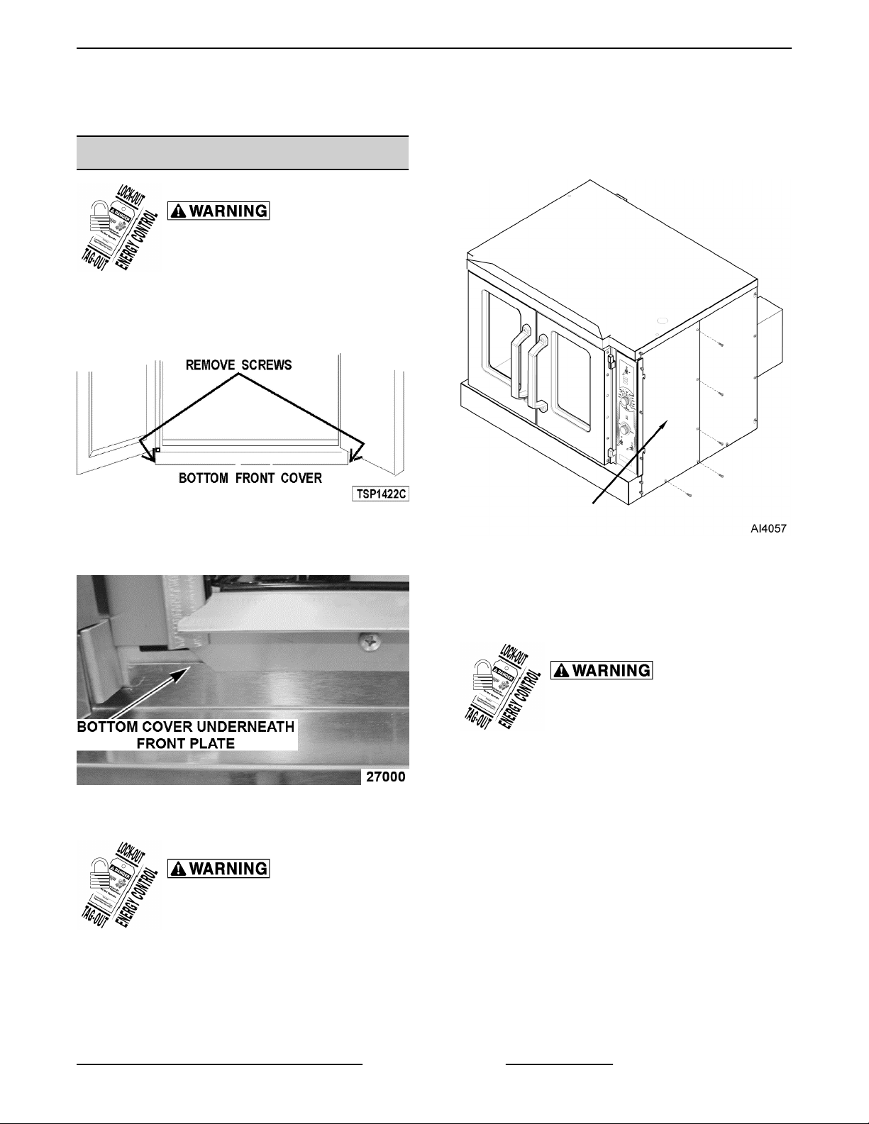
Bottom Front Cover
1. Remove four screws, two from each side of
bottom cover, then remove cover from oven.
Fig. 1
2. Reverse procedure to install. Verify bottom cover
is seated under front plate.
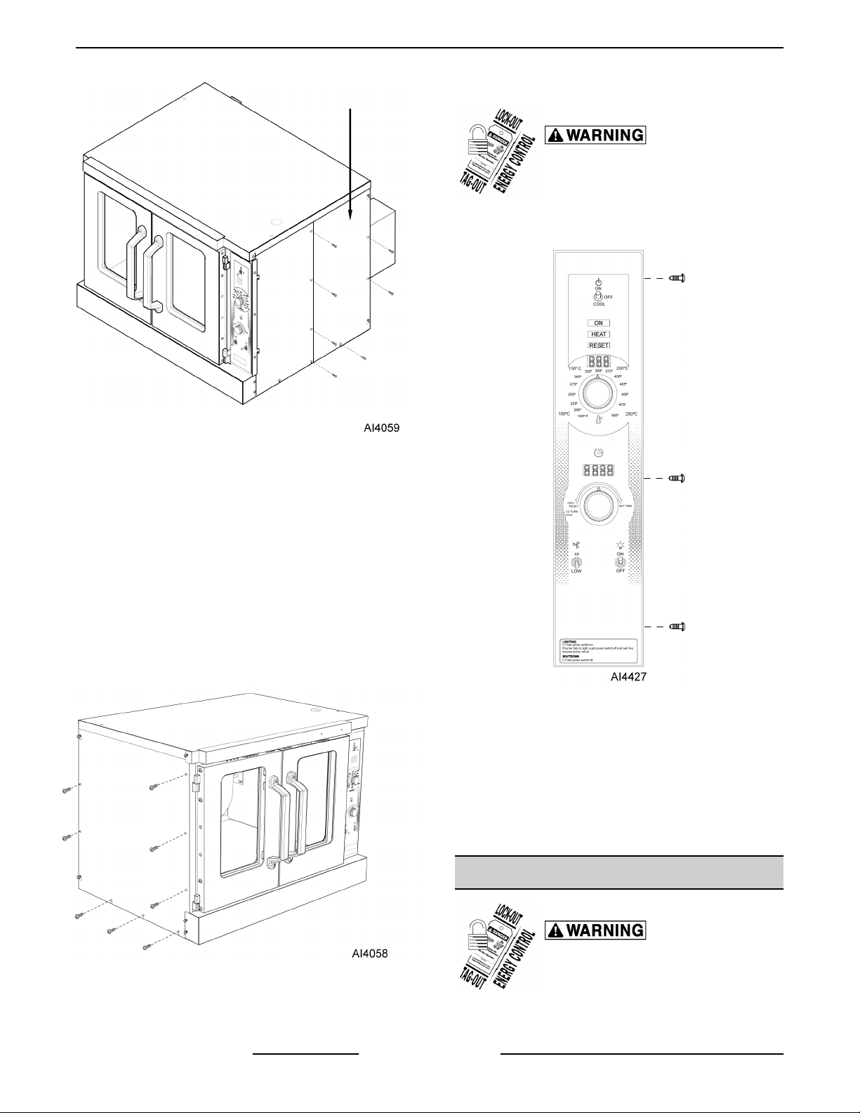
3. Remove screws along right side and bottom of
front panel.
Fig. 3
4. Slide right side front panel out.
Fig. 2
Right Side - Front Panel
Disconnect the
electrical power to the machine and
follow lockout / tagout procedures.
1. Loosen two screws near front of oven, which
secure bottom front cover.
2. Loosen screws on left side of front panel and top
cover screw.
5. Reverse procedure to install.
Right Side - Rear Panel
Disconnect the
electrical power to the machine and
follow lockout / tagout procedures.
1. Remove two middle screws along right side of
rear panel.
2. Remove screws along left side of rear panel.
3. Remove bottom screws on rear panel.
4. Loosen top and bottom screw along right side of
rear panel.
Page 5 of 31 F45652 (0217)
Page 6
VC5ED FULL SIZE ELECTRIC CONVECTION OVEN - REMOVAL AND REPLACEMENT OF PARTS
Control Panel
Disconnect the
electrical power to the machine and
follow lockout / tagout procedures.
1. Remove three screws on right side which secure
control panel, then lift up and pull away.
Fig. 4
5. Slide right side rear panel up and to the right to
remove.
6. Reverse procedure to install.
Left Side Panel
1. Remove screws along right side, middle left side,
and bottom.
2. Loosen screws on top and bottom on left side of
panel.
3. Loosen two screws near front of oven, which
secure bottom front cover.
Fig. 6
2. Disconnect temperature probe leads from solidstate temperature control.
3. Unplug wire harnesses connector to control
panel components.
4. Unplug Ground wire from control panel.
5. Reverse procedure to install.
Fig. 5
4. Lift up and pull away to remove.
5. Reverse procedure to install.
F45652 (0217) Page 6 of 31
1. Remove racks.
FAN COVER
Disconnect the
electrical power to the machine and
follow lockout / tagout procedures.
Page 7
VC5ED FULL SIZE ELECTRIC CONVECTION OVEN - REMOVAL AND REPLACEMENT OF PARTS
2. Lift fan cover up and out of oven.
Fig. 7
3. Reverse procedure to install.
CONTROL PANEL COMPONENTS
Disconnect the
electrical power to the machine and
follow lockout / tagout procedures.
1. Remove
2. Remove component being replaced.
3. Reverse procedure to install replacement
component.
4. Check oven for proper operation.
CONTROL PANEL.
Fig. 8
NOTE: Panel with standard controls shown.
COMPONENT PANEL
COMPONENTS
Disconnect the
electrical power to the machine and
follow lockout / tagout procedures.
1. Remove
NOTE: If right side panel is not accessible, this
component can be service by removing CONTROL
PANEL.
2. Disconnect wire leads to component being
replaced.
RIGHT SIDE PANEL.
3. Remove component.
4. Reverse procedure to install component.
5. Check oven for proper operation.
Page 7 of 31 F45652 (0217)
Page 8
VC5ED FULL SIZE ELECTRIC CONVECTION OVEN - REMOVAL AND REPLACEMENT OF PARTS
TEMPERATURE PROBE
Disconnect the
electrical power to the machine and
follow lockout / tagout procedures.
1. Remove RIGHT SIDE PANEL.
NOTE: If right side - front panel is not accessible, this
component can be serviced by removing CONTROL
PANEL.
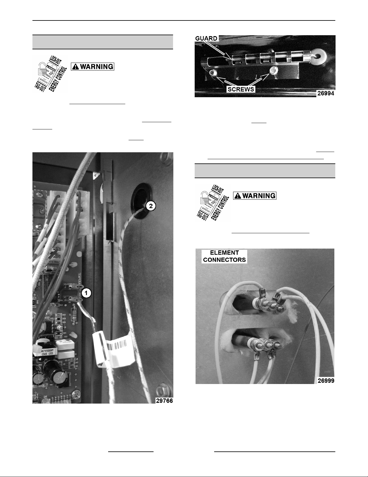
2. Disconnect the probe leads (1, Fig. 9) from the
solid state temperature control.
Fig. 10
5. Remove probe by pushing it through the oven
wall opening (2, Fig. 9) in control panel area.
6. Reverse the procedure to install the replacement
probe.
7. Adjust the temperature control. Refer to: SOLID
STATE TEMPERATURE CONTROL TEST .
HEATING ELEMENTS
Disconnect the
electrical power to the machine and
follow lockout / tagout procedures.
1. Remove RIGHT SIDE - REAR PANEL.
2. Disconnect element wire connectors.
3. Remove racks from cavity.
Fig. 9
3. Remove the racks from inside cavity.
4. Remove the probe guard.
F45652 (0217) Page 8 of 31
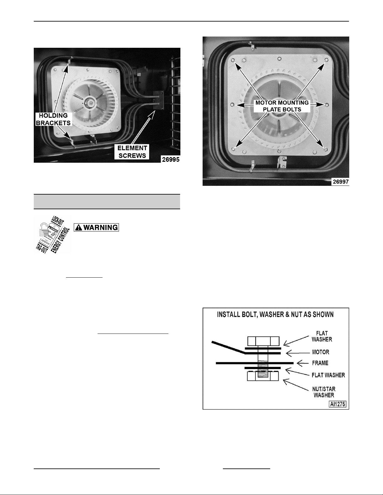
4. Remove FAN COVER.
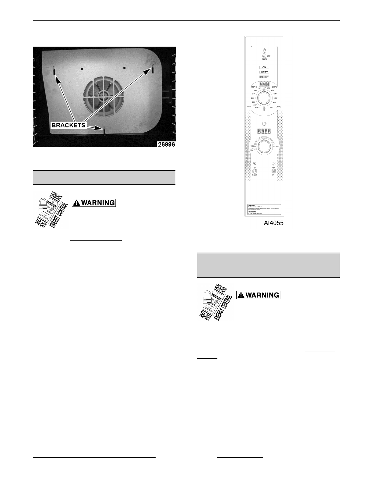
5. Remove screws on back wall holding brackets.
Fig. 11
Loosen element screws on side wall.
Page 9
VC5ED FULL SIZE ELECTRIC CONVECTION OVEN - REMOVAL AND REPLACEMENT OF PARTS
6. Pull elements forward, then away from right wall.
Fig. 12
7. Reverse the procedure to install the replacement
heating element.
Fig. 13
BLOWER AND MOTOR
Disconnect the
electrical power to the machine and
follow lockout / tagout procedures.
1. Take out the racks and rack supports.
2. Lift off FAN COVER.
3. If replacing:
A. Blower Only - Loosen bolts on blower hub
and using a bearing puller, remove blower
from motor shaft.
1) Reverse procedure to install and
perform BLOWER ADJUSTMENT.
B. Motor - perform step 3A and continue
procedure.
4. Remove bolts that secure the motor mounting
plate to the rear wall.
5. Place a piece of cardboard on the bottom of the
oven cavity to protect its surface from any
damage during motor assembly removal.
6. Pull the motor assembly into the oven cavity and
place it on the cardboard.
7. Remove the junction box cover from the motor,
disconnect lead wires and remove the conduit.
8. Remove motor mounting bolts and flat washers
then lift the motor from the mounting plate.
9. Position the replacement motor on the motor
mounting plate and install mounting bolts and
washers. Hand tighten mounting bolts only.
Fig. 14
10. Reconnect lead wires at the motor, replace
conduit and junction box cover.
Page 9 of 31 F45652 (0217)
Page 10
VC5ED FULL SIZE ELECTRIC CONVECTION OVEN - REMOVAL AND REPLACEMENT OF PARTS
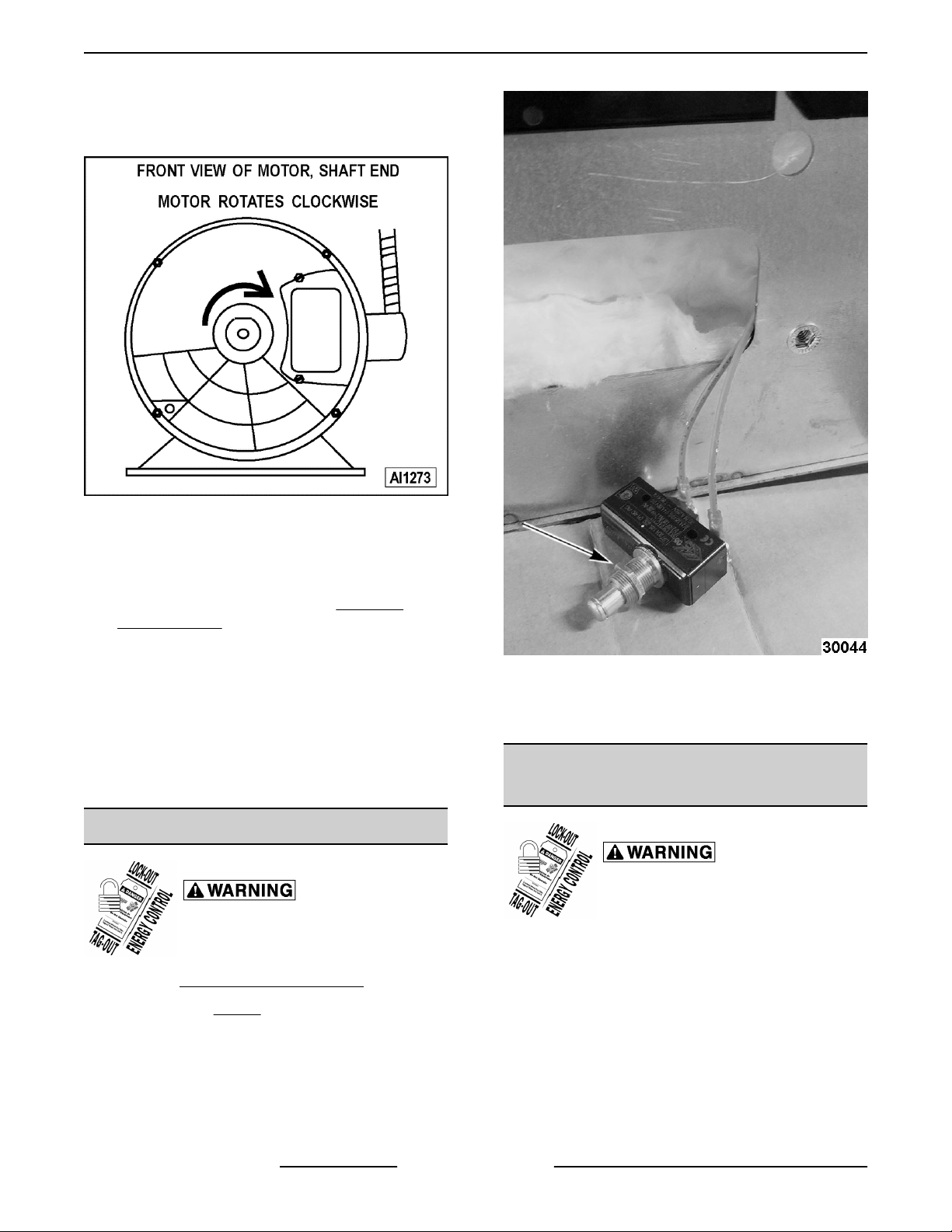
NOTE: Check data plate on motor for wiring
schematic. The motor must rotate clockwise when
viewed from the shaft end.
Fig. 15
11. Slide blower onto motor shaft until hub is flush
with end of shaft then tighten bolts.
12. Adjust motor position until blower is parallel to
motor mounting plate, Refer to: BLOWER
ADJUSTMENT.
13. Position motor mounting plate on the rear wall
and secure with screws and washers.
14. Replace the baffle panel.
15. Remove cardboard from the bottom of the oven
cavity.
16. Check oven for proper operation then replace
rack guides and racks.
DOOR SWITCH
Disconnect the
electrical power to the machine and
follow lockout / tagout procedures.
1. Remove
BOTTOM FRONT COVER.
Fig. 16
4. Disconnect lead wires to door switch.
5. Reverse procedure to install replacement switch.
ROLLER LATCH ASSEMBLY
(INDEPENDENT DOORS)
Disconnect the
electrical power to the machine and
follow lockout / tagout procedures.
1. Remove the screws that attach roller latch
assembly to door.
2. Unscrew nut (Fig. 16) holding door switch.
3. Pull door switch and washer out through bottom
panel opening.
F45652 (0217) Page 10 of 31
Page 11

VC5ED FULL SIZE ELECTRIC CONVECTION OVEN - REMOVAL AND REPLACEMENT OF PARTS
2. Remove the high limit thermostat cover/mounting
plate from inside the oven cavity at the top.
Fig. 17
2. Reverse procedure to install.
DOOR REMOVAL
1. Open door to a 90° angle.
2. Lift door up off hinges to remove.
Fig. 18
3. Reverse the procedure to install the replacement
door and check oven for proper operation.
HIGH LIMIT THERMOSTAT
Fig. 19
3. Disconnect lead wires from high limit thermostat.
NOTE: Remove the old RTV sealer from the cover
and mating surfaces inside the oven cavity and apply
new high temperature RTV sealer before installing.
4. Reverse procedure to install.
INTERIOR LIGHTS
Disconnect the
electrical power to the machine and
follow lockout / tagout procedures.
Do not touch the Halogen lamp with bare
hands. If lamp is exposed to oil from the skin, the life
will be reduced. Ensure lamp is free from oil and dirt
before replacing.
Bulb Replacement
1. Pull lamp cover off.
Disconnect the
electrical power to the machine and
follow lockout / tagout procedures.
1. Take out racks from the oven.
2. Grasp lamp using a clean cloth and remove from
lamp assembly.
Page 11 of 31 F45652 (0217)
Page 12

VC5ED FULL SIZE ELECTRIC CONVECTION OVEN - REMOVAL AND REPLACEMENT OF PARTS
Fig. 20
3. Reverse procedure to install new bulb.
Lamp Assembly Replacement
1. Remove racks in cavity.
2. Pull lamp cover off.
3. Remove RIGHT SIDE REAR PANEL.
Insert screw driver and push lamp assembly out
into cavity.
Fig. 21
4. Disconnect wires.
5. Reverse procedure to install new lamp assembly.
COOLING FAN
Disconnect the
electrical power to the machine and
follow lockout / tagout procedures.
1. Remove
NOTE: If right side - front panel is not accessible, this
component can be serviced by removing the
CONTROL PANEL.
2. Remove wire nuts from fan wire connections.
RIGHT SIDE FRONT PANEL.
F45652 (0217) Page 12 of 31
Page 13

VC5ED FULL SIZE ELECTRIC CONVECTION OVEN - REMOVAL AND REPLACEMENT OF PARTS
Fig. 22
3. Loosen the tab screw holding the fan to the
component panel. Rotate the tab so that the fan
will clear and remove the fan.
4. Reverse the procedure to install the replacement
fan and check for proper operation.
NOTE: The fan must be installed so air is pulled from
outside the rear of the oven and blown into the control
area. The arrow on the fan body indicates "air flow"
direction and should be pointing toward the controls.
Page 13 of 31 F45652 (0217)
Page 14

VC5ED FULL SIZE ELECTRIC CONVECTION OVEN - SERVICE PROCEDURES AND ADJUSTMENTS
SERVICE PROCEDURES AND ADJUSTMENTS
TEMPERATURE CONTROL
CALIBRATION
Certain procedures in
this section require electrical test or
measurements while power is applied
to the machine. Exercise extreme
caution at all times and follow Arc Flash
procedures. If test points are not easily
accessible, disconnect power and
follow Lockout/Tagout procedures,
attach test equipment and reapply
power to test.
NOTE: The temperature control module has a
programmable offset that can be applied to the set
temperature. This can be adjusted in 5 degree
increments up to 20 degrees in either direction.
1. Place a thermocouple in geometric center of
oven cavity.
2. Remove RIGHT SIDE FRONT PANEL to view
back of temperature control board.
• If it is more than 10° Fahrenheit, then complete
following steps.
1. Remove temperature control knob.
3. Turn oven on and set to 350° Fahrenheit.
4. Watch the red fault indicator. If light comes on
see TEMPERATURE CONTROL BOARD
FAULT INDICATOR for troubleshooting tips. If
light stays off go to next step.
5. Allow oven to stabilize (typically 3 cycles)
6. Record temperature when heat light goes off and
comes on for at least 2 cycles.
7. Calculate differential by subtracting temperature
when lamp goes out from temperature when
lamp comes on.
Differential = (Heat Lamp OFF - Heat Lamp ON)
• If differential is less than 20 degrees,
temperature control circuit is functioning
properly. If it is more than 20 degrees, turn off
oven and replace TEMPERATURE PROBE.
• Repeat CALIBRATION steps. Calculate average
temperature (Heat Lamp OFF temperature +
Heat Lamp ON temperature divided by 2).
Average = (Heat Lamp OFF + Heat lamp on divided
by 2)
• If Average is less than 10° Fahrenheit from dial
setting, thermostat is properly calibrated.
Fig. 23
2. Press and hold both + (plus) and the –
(minus) buttons for 3 seconds.
NOTE: Power light will start blinking and display will
show current offset.
3. Push “+” or “-“ button to increase or
decrease offset.
NOTE: Each press will change offset by 5 degrees.
NOTE: After 5 seconds of no activity controller will
automatically exit calibration mode.
F45652 (0217) Page 14 of 31
Page 15

VC5ED FULL SIZE ELECTRIC CONVECTION OVEN - SERVICE PROCEDURES AND ADJUSTMENTS
SOLID STATE TEMPERATURE
CONTROL TEST
Certain procedures in
this section require electrical test or
measurements while power is applied
to the machine. Exercise extreme
caution at all times and follow Arc Flash
procedures. If test points are not easily
accessible, disconnect power and
follow Lockout/Tagout procedures,
attach test equipment and reapply
power to test.
1. Remove
NOTE: If right side panel is not accessible, this
component can be serviced by removing CONTROL
PANEL.
RIGHT SIDE FRONT PANEL.
TEMPERATURE CONTROL BOARD FAULT INDICATOR
2. Place a thermocouple in the geometric center of
oven cavity.
NOTE: Oven temperature must be below 450°F.
3. Set the temperature control to the maximum
setting.
4. The green indicator light will flash once every 3
seconds if the board is receiving power. If it is off
the problem is not with the Temperature Control
Board. Refer to" TROUBLESHOOTING.
5. If the red fault indicator comes on count the
number of times it flashes and check
TEMPERATURE CONTROL BOARD FAULT
INDICATOR table to identify fault code.
Certain procedures in this section require electrical test or measurements while
power is applied to the machine. Exercise extreme caution at all times and follow Arc Flash
procedures. If test points are not easily accessible, disconnect power and follow Lockout/Tagout
procedures, attach test equipment and reapply power to test.
Code Description Action
1 Open Probe
2 Shorted Probe Replace TEMPERATURE PROBE.
3 No Heat
4 PCB Overheat
5 No Output
6 Output Shorted
Verify probe is plugged in. Replace
TEMPERATURE PROBE.
Run TEMPERATURE PROBE
TEST.
Verify cooling fan works. Clean air
intake at back of oven.
Replace temperature control PCB.
Refer to: CONTROL PANEL
COMPONENTS
Replace temperature control PCB.
Refer to: CONTROL PANEL
COMPONENTS
Page 15 of 31 F45652 (0217)
Page 16

VC5ED FULL SIZE ELECTRIC CONVECTION OVEN - SERVICE PROCEDURES AND ADJUSTMENTS
TEMPERATURE PROBE TEST
Certain procedures in
this section require electrical test or
measurements while power is applied
to the machine. Exercise extreme
caution at all times and follow Arc Flash
procedures. If test points are not easily
accessible, disconnect power and
follow Lockout/Tagout procedures,
attach test equipment and reapply
power to test.
Temperature to Resistance Chart
Degrees
(Fahrenheit)
77° 90k - 100k
200° 8354
250° 3794
300° 1903
250° 1032
400° 609
450° 374
500° 241
1. Place a shielded thermocouple in center of oven
cavity.
Resistance
HEATING ELEMENT TEST
Certain procedures in
this section require electrical test or
measurements while power is applied
to the machine. Exercise extreme
caution at all times and follow Arc Flash
procedures. If test points are not easily
accessible, disconnect power and
follow Lockout/Tagout procedures,
attach test equipment and reapply
power to test.
1. Turn the power switch ON and set the oven
temperature control to the highest setting.
2. Measure the voltage at the heating element
terminals and verify it against the data plate
voltage.
A. If voltage is incorrect, find the source of the
problem.
B. If voltage is correct, check current draw
(amps) through the heating element lead
wires.
NOTE: This method is preferred over a resistance
check when a clamp on type amp meter is available.
1) If current draw is correct then heating
element is functioning properly. See
HEATING ELEMENT VALUES table.
2. Turn oven on and set to 350° Fahrenheit.
3. Remove temperature control knob.
4. Hold down "-" (minus) button for 3 seconds to
enter diagnostic mode.
NOTE: Display should now show oven temperature
reported by probe.
5. Allow temperature to stabilize (typically 3 cycles).
• If thermocouple temperature is within 5°
Fahrenheit of display temperature, probe is
functioning properly.
• If temperature difference between
thermocouple and display is greater than 5
degrees but less than 20° Fahrenheit, refer
to: TEMPERATURE CONTROL
CALIBRATION to calibrate.
• If temperature difference is greater than 20°
Fahrenheit turn off oven, replace
TEMPERATURE PROBE, then repeat
TEMPERATURE PROBE TEST.
2) If current draw is not correct, turn the
power switch OFF and disconnect the
electrical supply to the oven.
a. Replace heating element, then
proceed to step 3.
C. If unable to check current draw, a resistance
check may indicate a malfunctioning
element.
1) Turn the power switch OFF and
disconnect the electrical supply to the
oven.
2) Remove the lead wires from the
heating element and check resistance
(ohms). See HEATING ELEMENT
VALUES table.
3. Check for proper operation.
F45652 (0217) Page 16 of 31
Page 17

VC5ED FULL SIZE ELECTRIC CONVECTION OVEN - SERVICE PROCEDURES AND ADJUSTMENTS
HEATING ELEMENT VALUES
VOLT.
KW PER
ELEMENT
208 4 19 19 10
240 4 16.5 16.5 14.5
480 4 8 8 57
1. Values in the table are nominal.
Tolerance is +5/-10%.
AMPS PER
ELEMENT
1 PH 3 PH
OHMS PER
ELEMENT
NOTES:
2. Voltage values are @ 60HZ.
3. Resistance values (ohms) are @
room temperature.
BLOWER ADJUSTMENT
Disconnect the
electrical power to the machine and
follow lockout / tagout procedures.
1. Loosen the motor mounting bolts.
2. Adjust the motor position until the blower is
parallel to and 1/4 inch away from the motor
mounting plate. Check for squareness of the
blower to the motor mounting plate at the top,
bottom, left and right of the blower.
A. If the blower is square then tighten motor
mounting bolts and proceed to
B. If the blower is not square continue
adjusting until proper spacing is achieved
then tighten motor mounting bolts.
STEP 4.
Fig. 25
3. Reverse the procedure to install.
DOOR STRIKE ADJUSTMENT
(INDEPENDENT DOORS)
1. Open the doors and inspect door strike for proper
shape.
A. Bend strike plate.
NOTE: If necessary, place shims between motor and
frame.
Fig. 24
Page 17 of 31 F45652 (0217)
Fig. 26
2. Open and close the doors several times while
observing the roller latch and strike plate
operation.
A. Replace ROLLER LATCH ASSEMBLY
(INDEPENDENT DOORS) if
malfunctioning.
3. Each oven door should open with a force of 8 to
25 pounds when pulled at the handle. The
adjustments must allow the doors to remain
closed during normal operation and allow
opening without exertion by the user.
Page 18

VC5ED FULL SIZE ELECTRIC CONVECTION OVEN - ELECTRICAL OPERATION
ELECTRICAL OPERATION
COMPONENT FUNCTION
Power Switch (S1) .... Determines the mode of operation; ON, OFF, or COOL down.
Oven Light Switch
(S3) ...................
Fan Speed Switch
(S2) ...................
Alarm/Buzzer ......... Signals the end of a "Cook" cycle when cooking time expires.
Cook Timer ........... Counts the "Cook" time of the product and signals the buzzer at the end of the cycle.
Door Switch .......... Allows the oven to operate when the doors are closed but stops the oven from operating
Blower Motor ......... Operates the oven cavity blower (convection fan).
Transformer .......... Provides 240VAC power to the oven control circuit and blower motor (480VAC models
Solid State
Temperature
Control ...............
High Limit
Thermostat ...........
1CON ................. Provides power to heating elements when energized. 1C is energized by the temperature
Power ON Light ....... Lit whenever the power switch (S1) is turned to ON or Cool Down mode.
Controls the oven cavity lights.
Controls blower motor speed between High and Low settings.
when the doors are opened.
only).
Monitors temperature sensor and regulates the oven cavity temperature by controlling
1CON to energize the heating elements when the control calls for heat.
Protects the oven from temperatures above 550°F by removing power from the heating
circuit. Auto resets at 500°F.
control when a call for heat is made.
Heat Light ............ Lit whenever temperature control is calling for heat.
Temperature Probe ... Senses the oven temperature for the solid state temperature. The probe is an RTD
(resistance temperature detector) of the Thermistor type. As temperature increases the
resistance value decreases.
Cooling Fan .......... Circulates cooler air from outside the oven to cool components in the control area.
Fuses ................. Protect control circuit.
F45652 (0217) Page 18 of 31
Page 19

VC5ED FULL SIZE ELECTRIC CONVECTION OVEN - ELECTRICAL OPERATION
COMPONENT LOCATION
Fig. 27
Page 19 of 31 F45652 (0217)
Page 20

VC5ED FULL SIZE ELECTRIC CONVECTION OVEN - ELECTRICAL OPERATION
CONTROL PANEL
1 ON/ OFF / COOL Switch
2 ON / HEAT / RESET Lights
3 Temperature Dial
4 Digital Time Readout
5 Timer
6 HI / LOW Fan Setting
7 Light ON / OFF Switch
8 Temperature Control Board
9 Timer Board
10 Light and Fan Speed Switch Board
11 Gentle Bake Switch
12 Fuses
CONTROL PANEL DIGITAL TEMPERATURE READOUT
F45652 (0217) Page 20 of 31
Page 21

VC5ED FULL SIZE ELECTRIC CONVECTION OVEN - ELECTRICAL OPERATION
Fig. 28
CONTROL PANEL DIGITAL TIME READOUT
Page 21 of 31 F45652 (0217)
Page 22

VC5ED FULL SIZE ELECTRIC CONVECTION OVEN - ELECTRICAL OPERATION
Fig. 29
F45652 (0217) Page 22 of 31
Page 23

VC5ED FULL SIZE ELECTRIC CONVECTION OVEN - ELECTRICAL OPERATION
Fig. 30
Page 23 of 31 F45652 (0217)
Page 24

VC5ED FULL SIZE ELECTRIC CONVECTION OVEN - ELECTRICAL OPERATION
Fig. 31
SEQUENCE OF OPERATION
Cook Cycle
1. Conditions.
A. Oven connected to correct voltage and is
properly grounded.
B. Power switch (S1) OFF.
C. Temperature dial set to lowest temperature
(fully counterclockwise).
D. High limit thermostat CLOSED.
F45652 (0217) Page 24 of 31
2. Power switch (S1) turned ON.
E. Oven doors closed (door switch contacts
CLOSED).
F. Oven cavity temperature below 140°F.
A. Power ON light (Amber) comes ON.
B. Solid state temperature control energized.
1) Heating elements powered and
heating starts.
2) 1C coil energized.
3) Heat light (Clear) comes on.
Page 25

VC5ED FULL SIZE ELECTRIC CONVECTION OVEN - ELECTRICAL OPERATION
C. Blower motor energized.
NOTE: Motor speed (Hi/Low) depends on position of
fan speed switch (S2).
D. Component cooling fan energized.
E. Power to oven cavity light switch (S3) wire
#1. Turns cavity lights ON/OFF; does not
affect "Cook" cycle.
3. Set temperature dial to desired "Cook"
temperature.
4. Oven reaches set temperature.
A. Temperature control de-energizes internal
relay and the normally open (N.O.) contacts
OPEN.
1) Heat light goes out.
2) 1C coil de-energized.
a. Power removed from heating
elements and heating stops.
5. The oven will continue to cycle on the
temperature control until the doors are opened or
power switch (S1) is turned to the OFF or COOL
down position.
B. Contacts 1 & 4 close.
1) Buzzer energized and sounds.
NOTE: The buzzer continues to sound until the timer
dial is set to the OFF position or additional time is set.
Cool Down Cycle
1. Conditions.
A. Oven is ON.
B. Oven cavity temperature needs to be
lowered.
C. Doors are open (door switch contacts
OPEN).
D. Fan speed switch (S2) set to "Hi".
2. Power Switch (S1) turned to COOL DOWN.
A. Power ON light (Amber) goes out.
B. Convection fan motor energized.
3. If doors are CLOSED (door switch contacts
CLOSED):
A. Power ON light (Amber) comes ON.
B. Component cooling fan energized.
Timer Cycle, Cooking
NOTE: The "Cook" timer operates independently of
the heating cycle. Additional time can be set or the
timer can be turned OFF throughout the cooking cycle.
1. With the power switch turned ON, power is
supplied to "Cook" timer terminal 1.
2. Set "Cook" timer to desired time.
A. Contacts 1 & 3 close, timer motor is
energized and timing "down" begins.
3. Time expires on "Cook" timer.
A. Contacts 1 & 3 open, timer motor is de-
energized and timing stops.
C. Power is supplied to:
1) "Cook" timer terminal 1. If a time is
dialed, timer will operate and buzzer
will sound when timer reaches zero.
2) Oven cavity light switch (S3) wire #1.
Turns cavity lights ON/OFF; does not
affect Cool down cycle.
4. The oven will remain in this condition until the
power switch (S1).
Page 25 of 31 F45652 (0217)
Page 26

VC5ED FULL SIZE ELECTRIC CONVECTION OVEN - ELECTRICAL OPERATION
WIRING DIAGRAMS
208-240V Wiring Diagram
VC5ED 208-240V Wiring Diagram
A ASSY, TEMP, CONTROL BOARD - TEMP
B ASSY, TIMER BOARD
C ASSY, SWITCH BOARD
D SWITCH, TOGGLE S.P.S.T
E LCOE GENTLE BAKE WIRE HARNESS
F WIRE SET, LIMIT SWITCH
G LCOG DOOR SWITCH, 2HP
H BLOCK, PORCELAIN ASSEMBLY
J LIMIT CONTROL 550F
K LCOE ELEMENT ASSY, 12KW
L PROBE, THERMISTOR
F45652 (0217) Page 26 of 31
Page 27

VC5ED FULL SIZE ELECTRIC CONVECTION OVEN - ELECTRICAL OPERATION
VC5ED 208-240V Wiring Diagram
M FUSE & HOLDER 15A
N TERMINAL BLOCK 3 POL
P CONTACTOR 40A 3 POLE
Q MOTOR 1/3 HP. 2 SPEED G.E.
R LCOE OVEN LAMP, 40W, 230V
S WIRE NUT BLUE
T FAN, COOLING
U LCOE DOOR SWITCH HARNESS
V LCOE LIGHT GND WIRE
W LCOE ACTUATOR HARNESS ASSY
X LCOE SENSING HARNESS ASSY
Y LCOE WIRE SET, SF
Z TRANSFORMER, 480V TO 240V
AA LCOE 480V WIRE SET
Page 27 of 31 F45652 (0217)
Page 28

VC5ED FULL SIZE ELECTRIC CONVECTION OVEN - ELECTRICAL OPERATION
480 VAC Wiring Diagram
VC5ED 208-240V Wiring Diagram
A ASSY, TEMP, CONTROL BOARD - TEMP
B ASSY, TIMER BOARD
C ASSY, SWITCH BOARD
D SWITCH, TOGGLE S.P.S.T
E LCOE GENTLE BAKE WIRE HARNESS
F WIRE SET, LIMIT SWITCH
G LCOG DOOR SWITCH, 2HP
H BLOCK, PORCELAIN ASSEMBLY
J LIMIT CONTROL 550F
K LCOE ELEMENT ASSY, 12KW
L PROBE, THERMISTOR
M FUSE & HOLDER 15A
N TERMINAL BLOCK 3 POL
F45652 (0217) Page 28 of 31
Page 29

VC5ED FULL SIZE ELECTRIC CONVECTION OVEN - ELECTRICAL OPERATION
VC5ED 208-240V Wiring Diagram
P CONTACTOR 40A 3 POLE
Q MOTOR 1/3 HP. 2 SPEED G.E.
R LCOE OVEN LAMP, 40W, 230V
S WIRE NUT BLUE
T FAN, COOLING
U LCOE DOOR SWITCH HARNESS
V LCOE LIGHT GND WIRE
W LCOE ACTUATOR HARNESS ASSY
X LCOE SENSING HARNESS ASSY
Y LCOE WIRE SET, SF
Page 29 of 31 F45652 (0217)
Page 30

VC5ED FULL SIZE ELECTRIC CONVECTION OVEN - TROUBLESHOOTING
TROUBLESHOOTING
Certain procedures in this section require electrical test or measurements while
power is applied to the machine. Exercise extreme caution at all times and follow Arc Flash
procedures. If test points are not easily accessible, disconnect power and follow Lockout/Tagout
procedures, attach test equipment and reapply power to test.
VC5ED
SYMPTOMS POSSIBLE CAUSES
1. Line voltage incorrect.
2. Fuse.
Blower motor doesn’t run with power switch in "ON" or
"COOL DOWN" or position.
Blower motor doesn’t run with power switch "ON", but
oven heats.
Blower motor doesn’t run in "Cool Down", but runs OK in
"ON" position.
Excessive Heat in oven.
Low heat in oven.
3. Power switch (S1) malfunction.
4. Fan speed switch (S2) malfunction.
5. Interconnecting wiring malfunction.
6. Motor inoperative.
1. Door switch malfunction.
2. Fan speed switch (S2) malfunction.
3. Interconnecting wiring malfunction.
4. Motor inoperative.
1. Power switch (S1) malfunction.
2. Interconnecting wiring malfunction.
1. Temperature probe malfunction.
2. Temperature control not calibrated.
3. Contactor malfunction.
4. Heating element(s) malfunction.
1. Line voltage incorrect.
2. High limit thermostat OPEN.
3. Contactor malfunction.
4. Heating element(s) malfunction.
5. Temperature probe malfunction.
6. Temperature calibration.
Timer inoperative or not functioning properly.
Component cooling Fan does not run.
F45652 (0217) Page 30 of 31
1. Interconnecting wiring malfunction.
2. Timer malfunction.
1. Interconnecting wiring malfunction.
2. Fan motor inoperable.
Page 31

VC5ED FULL SIZE ELECTRIC CONVECTION OVEN - TROUBLESHOOTING
SYMPTOMS POSSIBLE CAUSES
1. Fan cover not properly seated on hooks.
2. Convection Fan motor speed/direction.
3. Air flow baffles (Flag, Cavity or Vertical) missing or
damaged.
4. Line voltage incorrect.
Uneven Cooking.
Intermittent operation problems.
Oven will not turn on.
No heat, convection fan motor runs.
5. High limit thermostat malfunction.
6. Contactor malfunction.
7. Heating element(s) malfunction.
8. Doors out of adjustment.
9. Door roller out of adjustment or broken.
10. Door seals damaged.
1. Cooling fan malfunction.
2. Wiring connections loose.
3. High ambient temperatures.
1. Line voltage incorrect.
2. Control circuit fuses OPEN.
3. Power switch (S1) inoperative.
4. Transformer inoperative (480V only).
1. High limit thermostat OPEN.
2. Temperature probe malfunction.
3. Heating element malfunction.
4. Contactor malfunction.
No power to temperature control.
Door does not seal or shut properly
Wrong temperature on display.
5. Temperature control malfunction.
1. Power switch (S1) in "Cool Down".
2. Door switch malfunction.
1. Doors out of adjustment.
2. Door catch roller out of adjustment or broken
(independent doors).
3. Door seals damaged.
1. Temp board diagnostic buttons are stuck down.
Loosen two bottom screws attaching temp board to
control panel.
Page 31 of 31 F45652 (0217)
 Loading...