

Vulcan-Hart VC10HGP, ML-52441, VC20HGP, ML-52442, VC10FGP Installation & Operation Manual
...
GAS COMBI OVENS
MODEL
INSTALLATION &
OPERATION MANUAL
VC10HGP ML-52441
VC20HGP ML-52442
VC10FGP ML-52444
VC20FGP ML-114799
MODEL VC10HGP
VULCAN-HART COMPANY, P.O. BOX 696, LOUISVILLE, KY 40201-0696, TEL. (502) 778-2791
FORM 31010 Rev. B (7-99)
1

IMPORTANT FOR YOUR SAFETY
THIS MANUAL HAS BEEN PREPARED FOR PERSONNEL QUALIFIED TO INSTALL GAS
EQUIPMENT, WHO SHOULD PERFORM THE INITIAL FIELD START-UP AND
ADJUSTMENTS OF THE EQUIPMENT COVERED BY THIS MANUAL.
POST IN A PROMINENT LOCATION THE INSTRUCTIONS TO BE FOLLOWED IN THE
EVENT THE SMELL OF GAS IS DETECTED. THIS INFORMATION CAN BE OBTAINED
FROM THE LOCAL GAS SUPPLIER.
IMPORTANT
IN THE EVENT A GAS ODOR IS DETECTED, SHUT DOWN
UNITS AT MAIN SHUTOFF VALVE AND CONTACT THE
LOCAL GAS COMPANY OR GAS SUPPLIER FOR
SERVICE.
FOR YOUR SAFETY
DO NOT STORE OR USE GASOLINE OR OTHER
FLAMMABLE VAPORS OR LIQUIDS IN THE VICINITY OF
THIS OR ANY OTHER APPLIANCE.
WARNING: IMPROPER INSTALLATION, ADJUSTMENT,
ALTERATION, SERVICE OR MAINTENANCE CAN CAUSE
PROPERTY DAMAGE, INJURY OR DEATH. READ THE
INSTALLATION, OPERATING AND MAINTENANCE
INSTRUCTIONS THOROUGHLY BEFORE INSTALLING OR
SERVICING THIS EQUIPMENT.
IN THE EVENT OF A POWER FAILURE, DO NOT
ATTEMPT TO OPERATE THIS DEVICE.
2

Table of Contents
GENERAL . . . . . . . . . . . . . . . . . . . . . . . . . . . . . . . . . . . . . . . . . . . . . . . 4
INSTALLATION . . . . . . . . . . . . . . . . . . . . . . . . . . . . . . . . . . . . . . . . . . . 4
UNPACKING . . . . . . . . . . . . . . . . . . . . . . . . . . . . . . . . . . . . . . . 4
LOCATION . . . . . . . . . . . . . . . . . . . . . . . . . . . . . . . . . . . . . . . . 4
LEGS . . . . . . . . . . . . . . . . . . . . . . . . . . . . . . . . . . . . . . . . . . . . . 4
TABLE . . . . . . . . . . . . . . . . . . . . . . . . . . . . . . . . . . . . . . . . . . . . 4
CONDENSATE GUTTER . . . . . . . . . . . . . . . . . . . . . . . . . . . . . 4
LEVELING. . . . . . . . . . . . . . . . . . . . . . . . . . . . . . . . . . . . . . . . . 4
INSTALLATION CODES AND STANDARDS . . . . . . . . . . . . . 5
GAS CONNECTION . . . . . . . . . . . . . . . . . . . . . . . . . . . . . . . . . 5
VENT HOOD . . . . . . . . . . . . . . . . . . . . . . . . . . . . . . . . . . . . . . . 6
WATER REQUIREMENTS. . . . . . . . . . . . . . . . . . . . . . . . . . . . 6
PLUMBING CONNECTIONS . . . . . . . . . . . . . . . . . . . . . . . . . . 6
WATER CONNECTION . . . . . . . . . . . . . . . . . . . . . . . . . . . . . . 6
DRAIN CONNECTION . . . . . . . . . . . . . . . . . . . . . . . . . . . . . . . 7
ELECTRICAL CONNECTION . . . . . . . . . . . . . . . . . . . . . . . . . 7
START UP PROCEDURE . . . . . . . . . . . . . . . . . . . . . . . . . . . . 7
BEFORE FIRST USE . . . . . . . . . . . . . . . . . . . . . . . . . . . . . . . . 8
OPERATION . . . . . . . . . . . . . . . . . . . . . . . . . . . . . . . . . . . . . . . . . . . . . 8
DOOR OPENING AND CLOSING . . . . . . . . . . . . . . . . . . . . . . 8
GREASE FILTER . . . . . . . . . . . . . . . . . . . . . . . . . . . . . . . . . . . 8
LOADING THE OVEN . . . . . . . . . . . . . . . . . . . . . . . . . . . . . . . 9
UNLOADING THE OVEN . . . . . . . . . . . . . . . . . . . . . . . . . . . . . 9
PROGRAMMABLE CONTROLS . . . . . . . . . . . . . . . . . . . . . . 10
BAKING (CONVECTION BAKING - HOT AIR) . . . . . . . . . . . 12
CONVECTION BAKING APPLICATIONS . . . . . . . . . . . . . . . 13
STEAMING . . . . . . . . . . . . . . . . . . . . . . . . . . . . . . . . . . . . . . . 14
STEAMING APPLICATIONS . . . . . . . . . . . . . . . . . . . . . . . . . 15
COMBI (CONVECTION BAKING WITH STEAMING) . . . . . 16
COMBI APPLICATIONS. . . . . . . . . . . . . . . . . . . . . . . . . . . . . 17
USING THE TEMPERATURE PROBE . . . . . . . . . . . . . . . . . 18
TEMPERATURE PROBE APPLICATIONS . . . . . . . . . . . . . . 18
FIVE COOKING PHASES . . . . . . . . . . . . . . . . . . . . . . . . . . . 19
PROGRAMMING MEMORY . . . . . . . . . . . . . . . . . . . . . . . . . 20
EXAMPLE PROGRAM . . . . . . . . . . . . . . . . . . . . . . . . . . . . . . 21
RECALLING A PROGRAM FROM MEMORY . . . . . . . . . . . 22
MENU CARD . . . . . . . . . . . . . . . . . . . . . . . . . . . . . . . . . . . . . 23
COOK AND HOLD . . . . . . . . . . . . . . . . . . . . . . . . . . . . . . . . . 24
COOK AND HOLD APPLICATIONS . . . . . . . . . . . . . . . . . . . 25
CLEANING . . . . . . . . . . . . . . . . . . . . . . . . . . . . . . . . . . . . . . . 26
DAILY CLEANING . . . . . . . . . . . . . . . . . . . . . . . . . . . . . . . . . 26
COMPLETE CLEANING . . . . . . . . . . . . . . . . . . . . . . . . . . . . 26
MAINTENANCE . . . . . . . . . . . . . . . . . . . . . . . . . . . . . . . . . . . . . . . . . 28
REMOVAL OF LIME SCALE DEPOSITS . . . . . . . . . . . . . . . 28
FLUES . . . . . . . . . . . . . . . . . . . . . . . . . . . . . . . . . . . . . . . . . . . 28
MOTORS. . . . . . . . . . . . . . . . . . . . . . . . . . . . . . . . . . . . . . . . . 28
TROUBLESHOOTING . . . . . . . . . . . . . . . . . . . . . . . . . . . . . . . . . . . . 28
SERVICE. . . . . . . . . . . . . . . . . . . . . . . . . . . . . . . . . . . . . . . . . 28
3

Installation, Operation, and Care of
GAS COMBI STEAM & CONVECTION OVENS
KEEP THIS MANUAL FOR FUTURE USE
GENERAL
The Gas Combi Steam & Convection Ovens are single compartment ovens that provide steam and/
or convection heating. Various models can handle 10 or 20 shelves, Full or Half depth. A
Programmable control is provided on all size/depth combinations. The bold numbers and letters
explain the model-number conventions. An atmospheric steam generator can provide humidification
in the oven chamber.
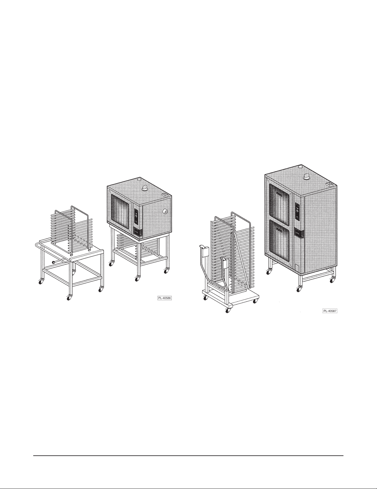
The 10 level models can be installed on an optional table or on a suitable countertop using the legs,
provided. Trolleys or landing tables (depending on size of oven) can load or unload all racks in one
easy motion. The hose spray accessory can be installed near the oven to facilitate easy cleaning.
INSTALLATION
UNPACKING
Immediately after unpacking the oven, check for possible shipping damage. If the oven is found to be
damaged, save the packaging material and contact the carrier within 15 days of delivery.
Prior to installation, verify that the electrical service and type of gas (natural or propane) agree with the
specifications on the oven data plate.
LOCATION
Allow space for operating the oven. Do not obstruct the ventilation ports above the oven. Do not install
the oven next to a major heat source, such as a griddle or fryer. All models require a minimum clearance
of 8" on the right side of the oven and 6" at the rear. The 8" clearance on the right side also provides
room for the gas connection. Additionally, model VC10FGP requires an 8" clearance on the left side.
LEGS (Provided for 10 Shelf Models)
Screw feet into legs at four corners and set oven on suitable countertop.
TABLE (Optional for 10 Shelf Models)
To assemble the oven onto the caster equipped table, insert four bolts from
underneath at the four corners and tighten until secure.
CONDENSATE GUTTER
Loosen screws under front of oven base and assemble condensate gutter to
bottom of oven. The 20 level ovens have a three segment condensate gutter and
dual input drain tube. Connect tube (if provided) to condensate gutter and drain.
NOTE: The 20 level gas ovens are equipped with casters, preassembled on the bottom of the oven.
LEVELING
To Drain
Tube
Condensate Gutter
Oven
Door
The oven must be placed in a level location. Using a spirit level or pan of water in the bottom of the
oven, make sure the oven is level, both front-to-back and side-to-side. After the drain is connected
(page 7), check for level by pouring water onto the floor of the compartment. All water should drain
through the drain opening.
4
INSTALLATION CODES AND STANDARDS
In the United States, install the oven in accordance with: 1) State and local codes; 2) National Fuel
Gas Code, ANSI-Z223.1, latest edition, available from American Gas Association, 1515 Wilson
Boulevard, Arlington, VA 22209; 3) National Electrical Code, ANSI/NFPA No. 70, latest edition; and
4) NFPA Standard #96,
Vapor Removal from Cooking Equipment
, latest edition, available from the
National Fire Protection Association, Batterymarch Park, Quincy, MA 02269.
In Canada, install the oven in accordance with: 1) Local codes; 2) CAN/CGA-B149.1, Installation for
Natural Gas Burning Appliances and Equipment, latest edition; 3) CAN/CGA-B149.2, Installation for
Propane Burning Appliances and Equipment, latest edition; and, 4) Canadian Electrical Code, Part 1,
CSA Standard C22.1, latest edition.
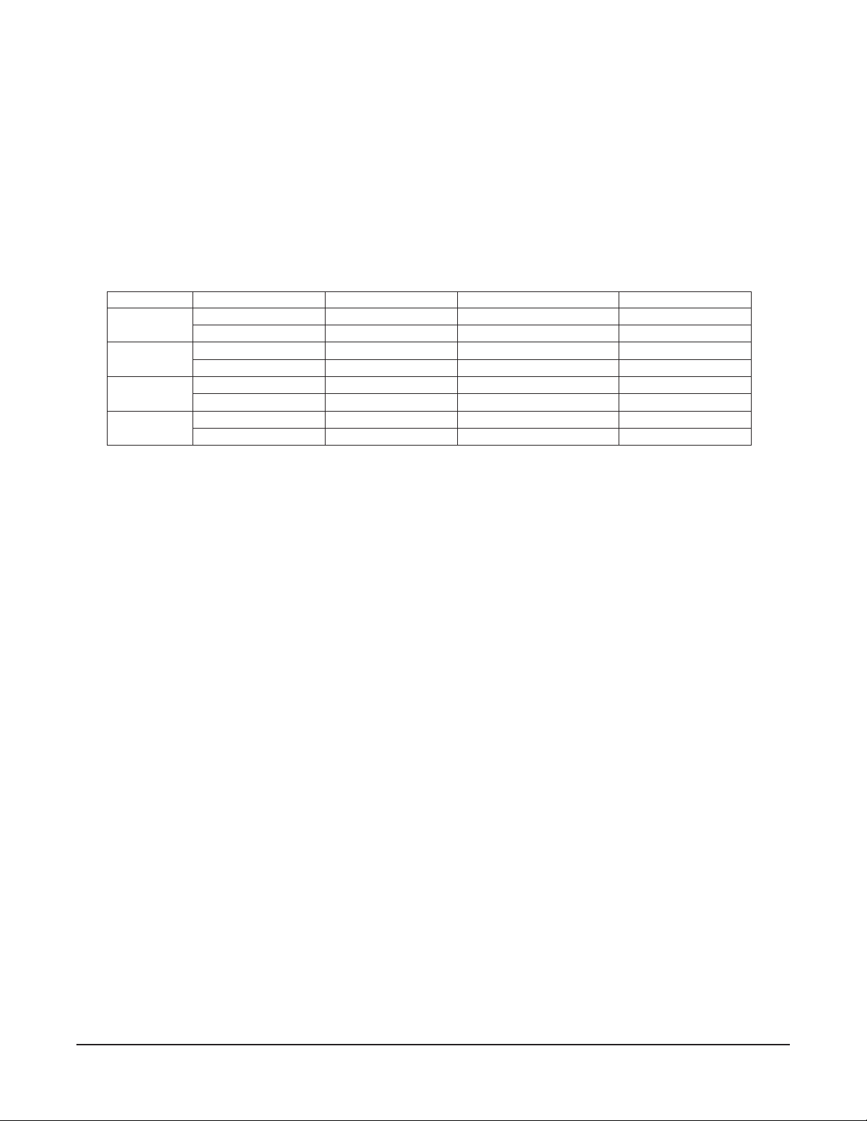
GNITARTUPNISAG
ledoMepyTsaGnevOrotareneGmaetSlatoT
PGH01CV
PGF01CV
PGH02CV
PGF02CV
larutaNrh/UTB000,76rh/UTB000,04rh/UTB000,701
enaporPrh/UTB000,96rh/UTB000,04rh/UTB000,901
larutaNrh/UTB000,58rh/UTB000,54rh/UTB000,031
enaporPrh/UTB000,58rh/UTB000,54rh/UTB000,031
larutaNrh/UTB000,07rh/UTB000,85rh/UTB000,821
enaporPrh/UTB000,07rh/UTB000,85rh/UTB000,821
larutaNrh/UTB000,051rh/UTB000,511rh/UTB000,562
enaporPrh/UTB000,051rh/UTB000,511rh/UTB000,562
GAS CONNECTION
All gas supply connections and any pipe joint compound must be resistant to the action of propane
gases. The machine connection is
3
/4" external thread. A manual valve (supplied) must be installed
in the gas supply line ahead of the appliance. Make sure piping is clean and free of obstructions, dirt,
or pipe joint compound. Recommended gas supply pressures are 7" W.C. (Water Column) for natural
gas and 11" W.C. for propane. The gas line must be capable of delivering gas to the oven without
excessive pressure drop at the rate specified on the rating plate.
The oven is equipped with a factory preset pressure regulator. Natural gas pressure regulators are
preset for 3.5" W.C. for both ovens and steam generators. Propane gas pressure regulators for 10 level
half and full and 20 level full ovens are preset for 10" W.C. for both ovens and steam generators.
Propane gas pressure regulators for 20 level half depth ovens are preset for 8" W.C. for oven burners
and 10" W.C. for steam generators.
Caster equipped ovens must be installed with a connector that complies with the
Connectors for Movable Gas Appliances
latest edition], and a quick-disconnect device that complies with the
Devices for Use with Gas Fuel
, ANSI-Z21.41 (latest edition) [in Canada, CAN 1-6.9, latest edition]. A
, ANSI-Z21.69 (latest edition) [in Canada, CAN/CGA-6.16,
Standard for Quick-Disconnect
Standard for
gas line strain relief must be provided to limit the movement of the oven without depending on the
connector and the quick-disconnect device or its associated piping to limit oven movement. Attach the
strain relief to the rear of the oven at the location provided. If it is necessary to disconnect the restraint
during service or maintenance, first turn off the gas supply. Reconnect the restraint before returning
the oven to its original installed location and turning the gas supply on.
WARNING: PRIOR TO LIGHTING, CHECK ALL JOINTS IN THE GAS SUPPLY LINE FOR LEAKS.
USE SOAP AND WATER SOLUTION. DO NOT USE AN OPEN FLAME.
The convection burner and the steam generator burner are ignited automatically by electric igniters;
there are no pilot lights. See Start Up Procedure, page 7.
Keep the appliance area free and clear from all combustible substances. Do not obstruct the flow of
combustion and ventilation air. Make sure there is an adequate supply of air in the room to allow for
combustion at the burners and exhaust by the vent hood system.
5

Testing the Gas Supply Piping System
When test pressures exceed
1
/2 psig (3.45 kPa), the oven and its individual shutoff valve must be
disconnected from the gas supply piping system.
When test pressures are 1/2 psig (3.45 kPa) or less, the oven must be isolated from the gas supply
piping system by closing its individual shutoff valve.
VENT HOOD
The Combi oven should be located under a suitable exhaust hood to vent steam, smoke, grease laden
vapors, etc. Information on the construction and installation of ventilating hoods may be obtained from
Vapor Removal from Cooking Equipment
, NFPA standard No. 96 (latest edition).
WATER REQUIREMENTS
Proper water quality can improve the taste of the food prepared in the oven, reduce liming in the steam
generator, and extend equipment life. Local water conditions vary from one location to another. The
recommended proper water treatment for effective and efficient use of this equipment will also vary
depending on the local water conditions. Ask your municipal water supplier for details about your local
water supply prior to installation.
Recommended water hardness is 2.0 to 4.0 grains of hardness per gallon with pH from 7.0 to 8.0.
Chlorides must not exceed 30 parts per million. Water hardness above 4.0 grains per gallon should
be treated by a water conditioner (water softener or in-line water treatment). Water hardness below
2.0 grains per gallon may also require a water treatment system to reduce potential corrosion. With
respect to water hardness, 17.1 parts per million is equal to 1 grain of hardness per gallon. Water
treatment has been shown to reduce costs associated with machine cleaning, reduce deliming of the
steam generator, and reduce corrosion of metallic surfaces in the steam generator.
Water supplies vary from one location to another. A local water treatment specialist should be
consulted before installing any steam generating equipment.
The Kleensteam® system by Everpure is an available Vulcan accessory. The Kleensteam system is
a passive chemical feeder that modifies the water supply by addition of a non-toxic chemical which
increases the acidity of water, reducing the alkalinity. This generally allows the steam generator to run
cleaner and require less frequent deliming. Kleensteam reduces the chemical taste and odor of
chlorine and filters out small particulates. The cartridge needs to be replaced every six months.
Sediment, silica, excess chlorides, or other dissolved solids may lead to a recommendation for
alternate form(s) of water treatment. Consult with a water treatment specialist and your Vulcan Sales
office for specific recommendations.
PLUMBING CONNECTIONS
WARNING: PLUMBING CONNECTIONS MUST COMPLY WITH APPLICABLE SANITARY, SAFETY
AND PLUMBING CODES.
WATER CONNECTION
Connect the potable water supply to the external-threaded nylon inlet (
3
/4" NSHT - National Straight
Hose Thread) located underneath the oven at the rear. Treat the nylon threads carefully so the
connection does not leak. A manual shutoff valve must be provided convenient to the oven; this valve
should be open when the oven is in operation. Water pressure should be between 20 and 80 psig.
Untreated water contains scale producing minerals which can precipitate onto the surfaces in the
steam generator tank. Due to the temperatures in the tank, the minerals can bake onto the surfaces
and components. This can result in early component failure and reduced product life.
Sensors in the steam generator tank use ions in the water to detect the water level. Do not use distilled
(fully demineralized or de-ionized) water as this could provide a false reading to the sensors.
6
Strainers and filters will NOT remove minerals from the water.
Refer to REMOVAL OF LIME SCALE DEPOSITS, page 28.
DRAIN CONNECTION
CAUTION: In order to avoid any back pressure in the oven, do not connect solidly to any drain
connection.
An adaptor collar is recommended for the machine drain connection, located underneath the oven at
the rear. The drain line should be plumbed to an open gap-type drain and include a trap. Drain piping
must have suitable pitch, have appropriate support along its length, and have no connection to other
piping. The material used in the drain line should be heat resistant to at least 212°F. The open drain
should be located between 3 and 5 feet away from the perimeter of the oven to reduce potential damage
from moisture-corrosion.
ELECTRICAL CONNECTION
Cord Connected Ovens
WARNING: THE SUPPLY CORD ON THIS OVEN IS PROVIDED WITH A GROUNDING PLUG. THE
OUTLET TO WHICH THIS PLUG IS CONNECTED MUST BE PROPERLY GROUNDED. IF THE
RECEPTACLE IS NOT THE PROPER GROUNDING TYPE, CONTACT AN ELECTRICIAN.
The wiring diagram is located on the inside surface of the right side panel as you face the oven.
START UP PROCEDURE
The Gas Combi Ovens are equipped with a gas burner for convection heating and a gas steam
generator for atmospheric steaming; two independent flues exhaust the burnt gases. Become familiar
with the entire manual before continuing with this Startup Procedure. Remove the tray rack, grease
filter, and fan baffle from the oven cavity. Turn gas and water on.
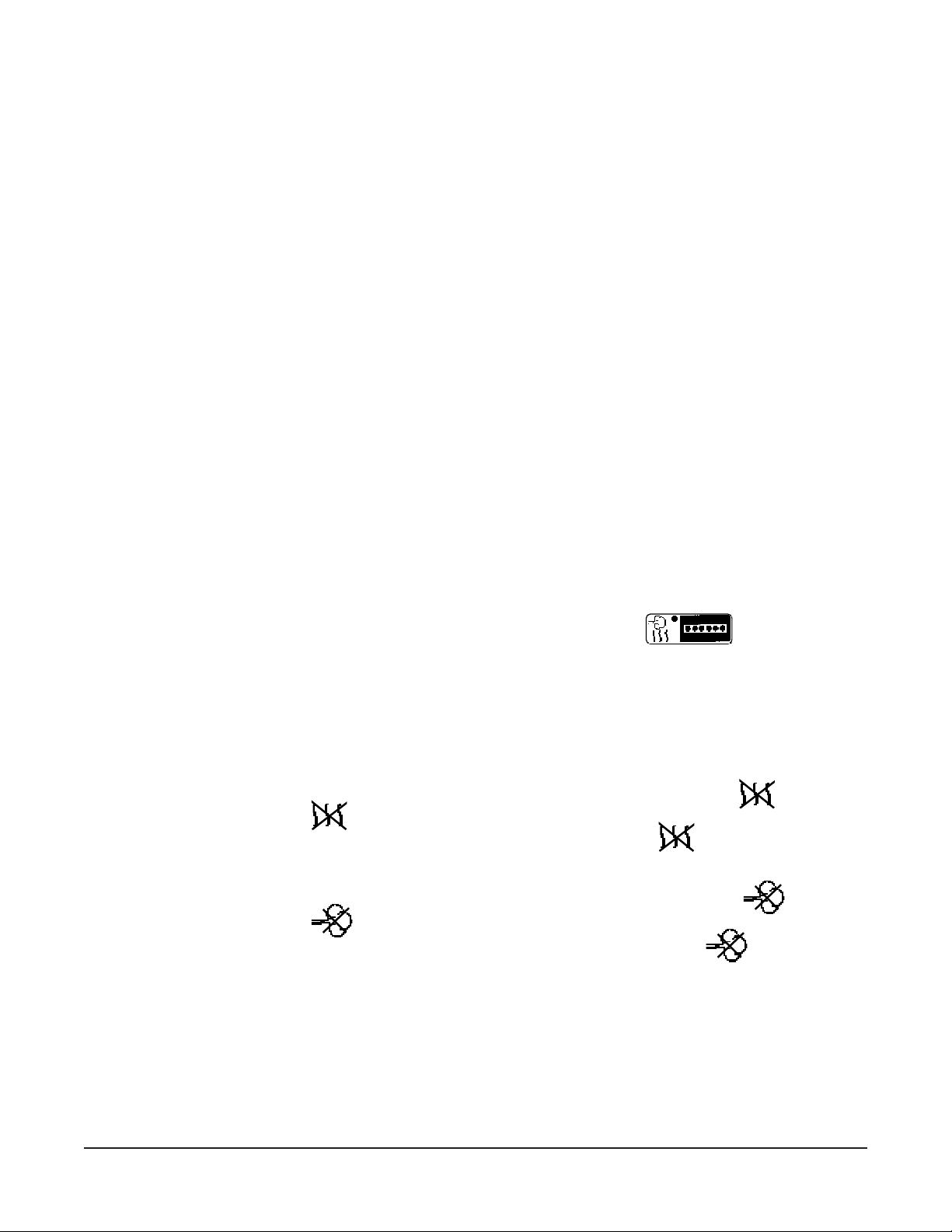
• Select Combi Mode and adjust the steam time to 50% by pressing
indicator lights are lit).
• Leave oven temp setting at 302°F and the timer display blank, [-]h [--]min.
• Close the oven door and press the Start Button. The oven convection fan rotates counterclockwise.
The oven flue vent should be open.
• After a delay of 50 seconds while the oven adjusts for Combi Mode, the sparker on the left side of
the burner should ignite the Convection Burner. Observe blue flame. After an additional 70 seconds,
the steam generator flame should ignite. Observe blue flame through window below controls.
If the Convection Burner does not ignite, the NO Convection Burner indicator light,
• Wait 30 seconds until the
• Reset the Convection Burner by pressing the Reset Button above the
• This procedure may need to be repeated several times until all of the air in the pipeline is replaced
by gas. The longer the pipe, the longer it will take to remove the air from the pipe.
If the Steam Generator Burner does not ignite, the NO Steam Burner indicator light,
• Wait 10 seconds until the
• Reset the Steam Generator Burner by pressing the Reset Button above the
• This procedure may need to be repeated several times until all of the air in the pipeline is replaced
by gas.
If a make-up air system is part of the vent hood, make sure there is no down-draft pushing hot
combustion gases from the flues back into the oven.
light starts to flash and the buzzer sounds.
light starts to flash and the buzzer sounds.
Press the ON button.
four times (four
, will be lit.
indicator light.
, will be lit.
indicator light.
Press Stop and observe that the pump drains the steam generator for about one minute. The door will
open. After the oven is cool, reinstall fan baffle, grease filter, and tray rack.
7
BEFORE FIRST USE
Before using the oven for the first time, it must be "burned in" to release any odors that might result from
heating the new surfaces in the oven. Operate the oven at 480°F for 45 minutes in Convection Mode.
OPERATION
WARNING: THE OVEN AND ITS PARTS ARE HOT. USE CARE WHEN OPERATING, CLEANING
OR SERVICING THE OVEN. THE COOKING COMPARTMENT CONTAINS LIVE STEAM. STAY
CLEAR WHEN OPENING DOOR.
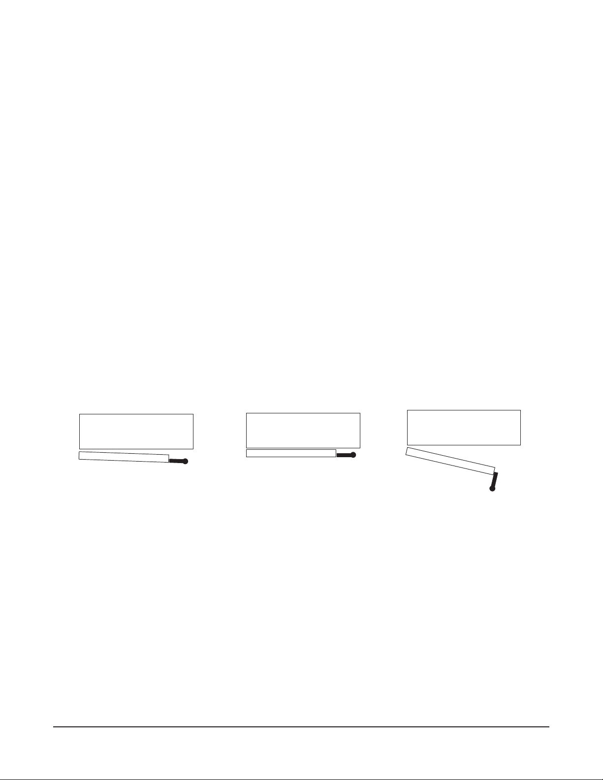
DOOR OPENING AND CLOSING
The oven door is equipped with an electrically powered lock. The oven is delivered with the door
latched and slightly open (Fig. 1) and can be opened by firmly pulling the door handle (Fig. 3). Push
the door until it connects with the latch but remains slightly open (Fig. 1). This is the position the door
should be in when the oven is not in use. The door should also be in this position after cooking to allow
steam to escape before fully opening the door. Push the handle until it is in line with the oven door.
If power has been connected, the door will now lock automatically, sealing the oven chamber (Fig. 2).
To release the door, rotate (pull) the handle 90 degrees. The door automatically releases to the
'latched and slightly opened' position. Allow a few seconds for steam to escape before pulling the door
open (Fig. 3).
→
Fig. 1 Fig. 2 Fig. 3
NOTE: In the event of a power failure, the door may be opened by pulling the handle firmly towards
you while firmly pressing against the front of the oven with the other hand.
GREASE FILTER
The grease filter in the rear of the oven chamber should be kept in place. See Cleaning, page 26, for
information on how to remove the grease filter and how to reinstall it.
8
LOADING THE OVEN
Open the door. Place the product to be cooked in suitable containers and slide into the racks or place
the containers securely on shelves in the oven.
When loading a 10 level oven with landing table (Fig. 4), the bottom frame of the rack should be secured
by the rotary lock. Move the loaded landing table to the front of the open oven; secure the landing table
to the oven by actuating the locking-clamp (or use your body to hold the landing table against the oven).
Rotate the lock-knob to release the rack and carefully roll the loaded rack into the oven, making sure
that the landing table does not separate from the oven during the transfer.
NOTE: When the landing table is not in use in the 10 level oven, make sure the insert retainer (delivered
with the oven) is fitted under the fan baffle to prevent the rack from tilting when pans are being removed.
When loading a 20 level oven with the trolley (Fig. 5), make sure the handle is locked in the down
position so the rack is held securely to the trolley with its lifting hooks. Carefully move the loaded trolley
completely into the open oven. When the rear frame of the rack is positioned behind the edge of the
retainer, raise the handle to lower the rack-frame to the oven floor.
Fig. 4 Fig. 5
UNLOADING THE OVEN
Allow the door to be 'slightly-opened' for a few seconds to allow hot air and steam to escape. Stand
behind the door while opening.
When unloading a 10 level oven, move the landing table (Fig. 4) so the clamp locks the landing table
to the front of the oven (or use your body to hold the landing table against the oven). Remove the
landing table handles and clamp them to the bottom of the hot oven rack. Carefully roll the hot rack
onto the landing table platform, making sure that the landing table does not separate from the oven
during the transfer. Rotate the knob to allow the rack to move completely to the front of the landing
table; and rotate the knob back to lock the rack in place.
When unloading a 20 level oven, move the trolley (Fig. 5) into the oven until the "lift-hooks" are inserted
into both sides of the front frame of the rack in the correct "lift" position. Lower the trolley handle until
it stops; the loaded-rack is lifted from its retainer and held securely to the trolley by the "lift-hooks".
The trolley may now be removed from the oven with the loaded rack securely held in place.
9
 Loading...