

Page 1
OPERATING, INSTALLATION,
SERVICE & PARTS
MANUAL FOR
CONVEYOR BAKER
MODELS VC-1224, VC-1824
VULCAN - HART COMPANY, P.O BOX 696, LOUISVILLE, KY 40201, TEL. (502) 778- 2791
FAX NO.: (502) 775-4053 TELEX: 442436
Page 2

IMPORTANT
OPERATING, INSTALLATION AND SERVICE PERSONNEL
Operating information for this equipment has been prepared for use by qualified and/or authorized operating
personnel.
All installation and service on this equipment is to be performed by qualified, certified, licensed and/or authorized
installation or service personnel, with the exception of any marked with a ? in front of the part number.
Service may be obtained by contacting the Factory Service Department, Factory Representative or Local Service
Agency.
DEFINITIONS
QUALIFIED AND/OR AUTHORIZED OPERATING PERSONNEL
Qualified or authorized operating personnel are those who have carefully read the information in this manual and are
familiar with the equipment's functions or have had previous experience with the operation of the equipment covered
in this manual.
QUALIFIED INSTALLATION PERSONNEL
Qualified installation personnel are individuals, a firm, corporation or company which either in person or through a
representative are engaged in, and are responsible for:
1. The installation of gas piping from the outlet side of the gas meter, or the service regulator when the meter is not
provided, and the connection and installation of the gas appliance. Qualified installation personnel must be
experienced in such work, be familiar with all precautions required, and have complied with all requirements of
state or local authorities having jurisdiction. Reference in the United States of America - National Fuel Gas code
ANSI Z223.1 (Latest Edition). In Canada-Canadian Standard CAN1-B149.1 NAT. GAS (Latest Edition) or CAN1B149.2 PROPANE (Latest Edition).
2. The installation of electrical wiring from the electric meter, main control box or service outlet to the electric
appliance. Qualified installation personnel must be experienced in such work, be familiar with all precautions
required, and have complied with all requirements of state or local authorities having jurisdiction. Reference: In
the United States of America-National Electrical Code ANSI NFPA No. 70 (Latest Edition). In Canada-Canadian
Electrical Code Part 1 CSA-C22.1 (Latest Edition).
QUALIFIED SERVICE PERSONNEL
Qualified service personnel are those who are familiar with Vulcan equipment who have been endorsed by the
Vulcan-Hart Corporation. All authorized service personnel are required to be equipped with a complete set of service
parts manuals and stock a minimum amount of parts for Vulcan equipment.
SHIPPING DAMAGE CLAIM PROCEDURE
For your protection, please note that equipment in this shipment was carefully inspected and packed by skilled
personnel before leaving the factory. The Transportation Company assumes full responsibility for safe delivery upon
acceptance of this shipment.
If shipment arrives damaged:
1. VISIBLE LOSS OR DAMAGE — Be certain this is noted on freight bill or express receipt and signed by person
making delivery.
2. FILE CLAIM FOR DAMAGES IMMEDIATELY — Regardless of extent of damage.
3. CONCEALED LOSS OR DAMAGE — If damage is unnoticed until merchandise is unpacked, notify transportation
company or carrier immediately, and file "concealed damage" claim with them. This should be done within (15)
days of date of delivery is made to you. Be sure to retain container for inspection.
We cannot assume responsibility for damage or loss incurred in transit. We will, however, be glad to furnish you
with necessary documents to support your claim.
PLEASE RETAIN THIS MANUAL FOR FUTURE REFERENCE
Page 3

IMPORTANT NOTES FOR ALL VULCAN APPLIANCES
1. These units are produced with the best possible workmanship and material. Proper installation is vital if best performance and
appearance are to be achieved. Installer must follow the installation instructions carefully.
2. Information on the construction and installation of ventilating hoods may be obtained from the "Standard for the installation of
equipment for the removal of smoke and grease laden vapors from commercial cooking equipment," NFPA No. 96 (latest
edition) available from the National Fire Protection Association, Batterymarch Park, Quincy MA 02269.
3. For an appliance equipped with a flexible electric supply cord, the cord is equipped with a three-prong (grounding) plug. This
grounding plug is for your protection against shock hazard and should be plugged directly into a properly grounded three-prong
receptacle. Do not cut or remove the grounding prong from this plug. If the appliance is not equipped with a grounding plug, and
electric supply is needed, ground the appliance by using the ground lug provided (refer to the wiring diagram).
(FOR GAS APPLIANCES ONLY)
4. Do not obstruct the air flow into and around the appliance. This air flow is necessary for proper combustion of gases and for
ventilation of the appliance. Provisions for ventilation of incoming air supply for the equipment in the room must be in accordance
with National Fuel Gas Code ANSI Z223.1 (latest edition).
5. Do not obstruct the flow of flue gases from the flue duct (when so equipped) located on the rear (or sides) of the appliance. It is
recommended that the flue gases be ventilated to the outside of the building through a ventilation system installed by qualified
personnel.
6. For an appliance equipped with casters, (1) the installation shall be made with a connector that complies with the Standard for
Connectors for Movable Gas Appliances, ANSI Z21.69 (latest edition), and Addenda, Z21.69a (latest edition), and a quickdisconnect device that complies with the Standard for Quick-Disconnect Devices for Use With Gas Fuel, ANSI Z21.41 (latest
edition), and Addenda, Z21.41a (latest edition) and Z21.41b (latest edition), and (2) adequate means must be provided to limit
the movement of the appliance without depending on the connector and the quick-disconnect device or its associated piping to
limit the appliance movement. If disconnection of the restraint is necessary, reconnect this restraint after the appliance has been
returned to its originally installed position.
7. The appliance and its individual shutoff valve must be disconnected from the gas supply piping system during any pressure
testing of that system at test pressures in excess of 1/2 psig (3.45 k Pa).
8. The appliance must be isolated from the gas supply system by closing its individual manual shutoff valve during any pressure
testing of the gas supply system at test pressures equal to or less than 1/2 psig (3.45 k Pa).
CAUTIONS
FOR YOUR SAFETY
DO NOT STORE OR USE GASOLINE OR OTHER FLAMMABLE VAPORS AND LIQUIDS
IN THE VICINITY OF THIS EQUIPMENT OR ANY OTHER APPLIANCE.
1. KEEP THE APPLIANCE FREE AND CLEAR FROM ALL COMBUSTIBLE SUBSTANCES.
2. IN THE EVENT A GAS ODOR IS DETECTED, SHUT UNIT (S) DOWN AT THE MAIN
SHUTOFF VALVE AND CONTACT THE LOCAL GAS COMPANY OR GAS SUPPLIER
FOR SERVICE.
3. POST IN A PROMINENT LOCATION, INSTRUCTIONS TO BE FOLLOWED IN THE EVENT
THE SMELL OF GAS IS DETECTED. THIS INFORMATION MAY BE OBTAINED FROM A
LOCAL GAS SUPPLIER.
Page 4

CONVEYOR BAKER 1224 or 1824 - OPERATING,
2
INSTALLATION, SERVICE AND PARTS MANUAL - INDEX
This Conveyor Baker is produced with the best possible
workmanship and material. Proper usage and maintenance will
result in many years of satisfactory performance.
DESCRIPTION PAGE
We suggest that you thoroughly read this entire manual and
carefully follow all of the instructions provided.
DEFINITIONS OF PERSONNEL (Operating, Installation and Service) and
SHIPPING DAMAGE CLAIM PROCEDURES
IMPORTANT NOTES 1
INDEX 2
GENERAL INFORMATION 2
INSTALLATION 3
OPERATING 3
CLEANING 4
TROUBLE SHOOTING 4
SPECIFICATIONS 5
PARTS REPLACEMENT INSTRUCTIONS 5-6
ASSEMBLY DRAWING 6
BELT DRIVE COMPONENTS 7
ELECTRICAL COMPONENTS 8
ELECTRICAL SCHEMATICS - SINGLE PHASE 9
(Inside Front Cover)
ELECTRICAL SCHEMATICS - THREE PHASE 10
PARTS LIST 11-12
REVISION PAGE (Inside Back Cover)
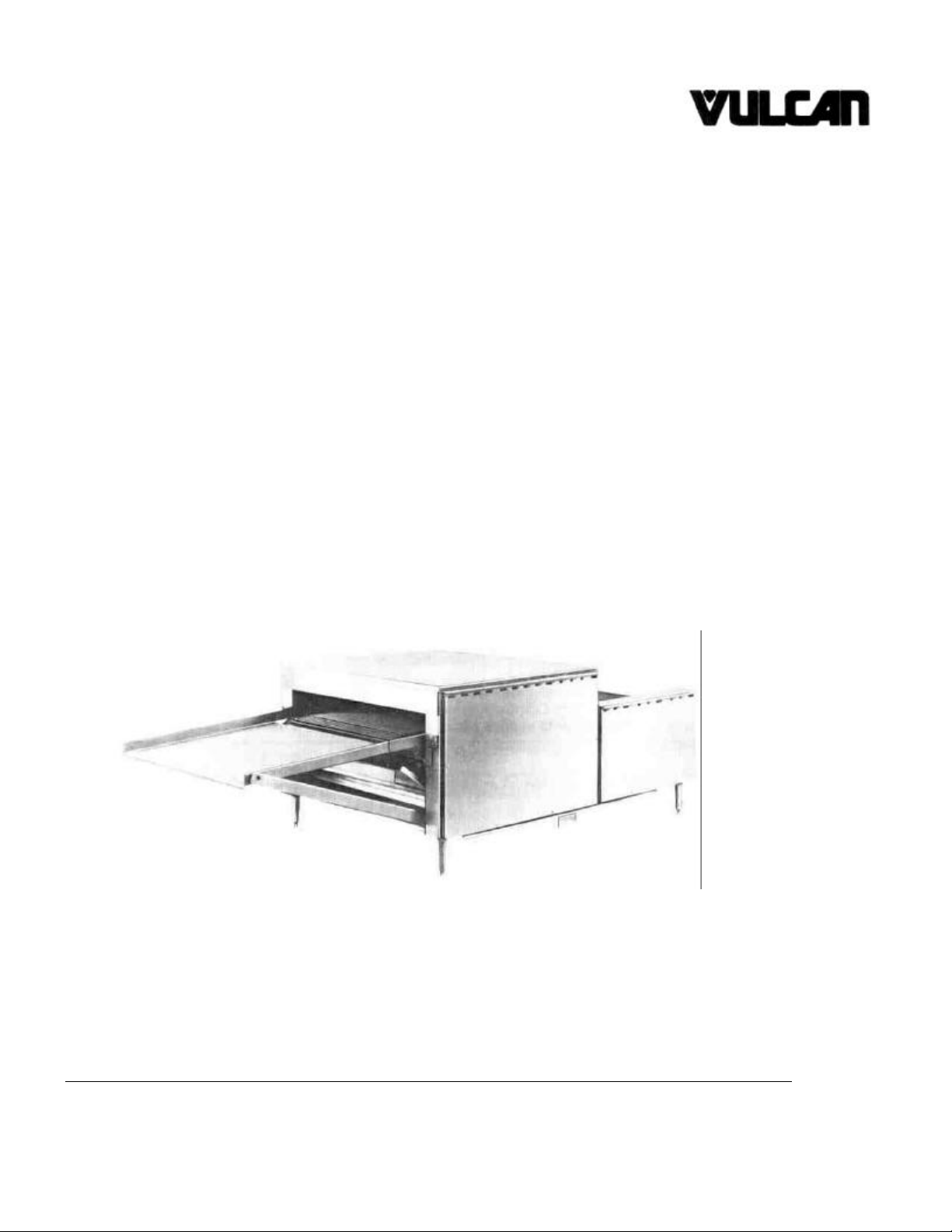
GENERAL INFORMATION
The Conveyor Baker is designed for table or counter top
operation. It uses infra-red, quartz sheathed heaters in
independently controlled groups to meet a wide range
of baking requirements. By adjustment of the heater voltage
regulators and the belt speed controls, an almost infinite range
of baking conditions can be obtained.
Page 5

INSTALLATION
The Conveyor Baker has been inspected and tested at the
factory prior to shipment.
CAUTION: Upon receipt, check for visible damage. If
damaged in shipment, check with the carrier for claim
adjustment.
Unpack the Conveyor Baker and remove all packing materials.
Heaters are packed in the long boxes - do not throw them
away. When finished, you should have the following parts:
Conveyor Baker
Hood
Top Reflector
Slide
Ramp
14 Heaters
(See assembly drawing on page 6.)
Place the baker on a flat horizontal surface at the desired
location.
CAUTION: Keep the baker at least 6 inches from any
vertical wall.
The baker may be leveled by screwing the tips of the legs in or
out.
Slide the crumb tray into the channels under the body.
Unhook the belt at the link with the hooks left partly open. Allow
the belt to run out the rear end of the machine. Remove the
idler assembly.
Install the 8 bottom heaters by placing one end in a socket on
one side and pushing in until the tip of the heater on the
opposite end clears the top of the socket
as you guide it into place. Rotate each heater after insertion to
insure that it is correctly seated. It should rotate smoothly.
Place the bottom reflector in the troughs provided for it. The
bottom reflector is not a crumb catcher and the angles should
face down.
Replace the idler assembly and reinstall the belt by pulling it
forward over the idler assembly and along the belt supports
until you can hook the free ends together.
NOTE: For best operation the conveyor belt should be always
installed with the hooks trailing away from the direction of
travel. See the inset on page 6.
Install the 6 top heaters.
Place the top reflector on its support rods. Both angles go
inside the support rods.
Place the hood on top of the body and press down firmly.
Install the slide on the two support rods at the rear of the body.
Install the ramp by dropping the tongues into grooves over the
idler assembly brackets. The ramp supports fit onto the
projecting pegs at the bottom corners of the baker.
The assembly is now complete.
CAUTION: Have the wiring to the wiring box on the unit
installed by a qualified electrician. The 1224 will require a
30 amp service. The 1824 will require a 50 amp service.
(Single phase.).
OPERATING
CAUTION: Do not operate the oven unless the crumb tray
(item #45) is in place.
Turn on the power at the main switch. Turn on the speed
control. Turn all heater controls to maximum and run the baker
for 1/2 hour before its first use.
Exact adjustment of the heat controls and the belt speed will be
determined by your particular requirements and location. The
bottom heaters are in two groups of 4. The top heaters are in
one group of 6. The output wattage of each individual group
may be varied with the appropriate controls.
NOTE: Numbers on the dials are for reference and do not refer
to any specific temperature.
3
Page 6

CLEANING
To clean the belt, turn all heaters to the maximum settings.
Clean the belt with a soft clean wet cloth dipped in cold water.
CAUTION: Do not use steel wool or abrasive cleansers to
clean the belt as they may damage the Silverstone coating.
Other removable parts may be washed in soap and water after
the baker has been shut off and allowed to cool. The baker
itself may be cleaned with any standard commercial cleaner.
We do not recommend steam cleaning.
TROUBLE SHOOTING
IF THE MACHINE BLOWS A FUSE OR TRIPS A CIRCUIT
BREAKER
1. Check that other devices are not overloading the circuit.
Ideally, the Conveyor Baker should have its own circuit: 30
amps for the 1224; 50 amps for the 1824. (Single phase)
2. Shorts may be accompanied by sputtering sounds or sparks.
CAUTION: Shut off all the power to the unit before
removing the front or side panels.
3. Remove the side panels and the control panel and check for
burned spots or loose connections where shorts may have
occurred.
IF THE HEATERS DO NOT LIGHT
1. Heater controls may be turned down too low to cause a
visible glow, even though some heat will still be emitted - a
phenomenon called "black heat".
2. One fuse or circuit breaker to one input wire may be off. In a
single phase unit, all heaters will not light. In a three-phase
oven, one group of heaters may be lit. The motor may or may
not run, depending on which phase is affected.
3. If one group of heaters does not light, the probable cause is
either a loose connection or a failure of the voltage regulator for
that group.
CAUTION: Shut off all power before removing the control
panel or side panels.
CAUTION: High voltage with the possibility of electric
shock hazard is inside this unit. Therefore, before cleaning
the conveyor baker, shut off the power to it to eliminate the
danger of an electric shock.
CAUTION: Quartz heaters are self-cleaning and do not
need to be washed. In particular, DO NOT immerse them in
water.
4. If two heaters do not light, check to see that they are
correctly seated in the sockets. It should be possible to rotate
them smoothly if they are properly seated. Check that one is
not burned out. Check for a loose or broken wiring connection.
IF THE BELT DOES NOT RUN
1. Check that the conveyor belt is not caught or jammed.
NOTE: The belt should be installed with the hooks on the links
facing up and trailing away from the direction of travel. See
inset sketch on page 6.
2. If the motor runs but the belt does not run, or runs irregularly,
check for a loose setscrew in the drive sprockets. See the
drawing of the belt drive components on page 7.
3. If the motor does not run, check for jammed motor drive
chain.
4. If the motor still does not run, remove the control panel.
CAUTION: Shut off all power to the machine before
removing the control panel.
Check that wires are clear of the cooling fan on the rear of
motor. Check for a loose wiring connection in the motor circuit.
Check for a defective motor or speed control.
4
Page 7

SPECIFICATIONS
UNIT CONSTRUCTION 302/304 Stainless Steel 302/304 Stainless Steel
OVERALL DIMENSIONS
Length 45" 45"
Width 21" 27"
Height 24" 24"
INPUT POWER REQUIREMENTS 208-240V 208-240V
HEATERS Quartz, 300 Watt Quartz, 500 Watt
CONVEYOR BELT 12" Wide Silverstone coated 18"Wide Silverstone coated
1224 1824
60 Hz., 4.2 KW 60Hz.,7KW
1 or 3 Phase 1 or 3 Phase
PARTS REPLACEMENT INSTRUCTIONS
HOW TO REPLACE A MOTOR
(Refer to the drawing on page 7.)
CAUTION: Shut off all power to the machine before
removing the control or side panels.
1. Remove the control panel and the front right side cover
panel.
2. Loosen the motor mount bolts (item #5) and slide the motor
forward to remove the belt drive chain (item #30).
3. Loosen the setscrew (item #29) on the motor drive sprocket
(item #27) and remove the sprocket.
4. Disconnect the motor wires.
5. Unscrew the motor mount bolts (item#5) and remove the old
motor.
6. Install the new motor. Be sure to keep the flat washers (item
#7) and the lock washers (item #6) on the motor mount bolts
(item #5) in their correct order. See sketch below. Do not
tighten the bolts yet.
7. Mount the motor drive sprocket (item #27) on the motor shaft.
Be sure to tighten the setscrew against the flattened part of the
motor shaft.
8. Slide the motor forward and install the drive chain (item #30)
on the belt drive sprocket (item #28) and the motor drive
sprocket (item # 27).
9. Slide the motor back to tighten the drive chain. Do not
overtighten the drive chain - you should be able to wiggle the
chain from side to side at least 1/8" then tighten the motor
mount bolts (item #5).
10. Pass the motor wire through the bushing (part #52) and
reconnect to the speed control. Reconnect the other motor wire
inside control compartment.
11. Remount the control panel.
12. Remount the side panel and test run the unit.
HOW TO REPLACE A VOLTAGE REGULATOR
(Refer to the drawing on page 8.)
CAUTION: Shut off all power to the machine before
removing the control panel.
1. Unscrew the control panel mounting bolts (item #1) and
remove the control panel.
2. Unscrew the wire nuts from the control to be replaced.
3. Loosen the setscrew on the control knob (item #11) and
remove the knob.
4. Remove the retaining nut (item#9) and remove the
potentiometer.
5. Unscrew the mounting nuts (item #18) to remove the
regulator (item #13).
6. Mount the new regulator.
7. Mount the new potentiometer and tighten. Rotate the
potentiometer shaft fully clockwise and place the control knob
(item#11) on the shaft. Rotate clockwise until the arrow lines up
with 100 on the dial. Tighten the setscrew.
8. Reconnect the wiring and screw the wire nuts on tight.
9. Remount the control panel.
5
Page 8

PARTS REPLACEMENT INSTRUCTIONS (Continued)
6A
HOW TO REPLACE A MOTOR SPEED CONTROL
CAUTION: Shut off all power to the machine before
removing the side panel.
1. Remove the right front side cover.
2. Unscrew the wire nuts connecting the speed control (item
#8) to the wires entering the control compartment.
3. Loosen the setscrew on the control knob (item #11), and
remove the knob.
4. Remove the front retaining nut (item #9) and remove the
speed control.
5. Be sure the rear-retaining nut on the new speed control is
the same distance from the housing as on the old speed
control. Slide the lockwasher (item #10) on, insert the new
speed control through the hold in the housing, and screw on the
front retaining nut. Do not overtighten.
6. Rotate the control shaft clockwise as far as it will go. Place
control knob (item #11) on the control shaft and turn it
clockwise until the arrow lines up with 100 on the dial. Tighten
the setscrew.
7. Reconnect the wiring and screw on t he wire nuts.
8. Remount the side cover panel.
ASSEMBLY DRAWING
Page 9

BELT DRIVE COMPONENTS
Page 10

Page 11

ELECTRICAL SCHEMATICS - MODEL 1224 & 1824 - 1 PHASE
Page 12

ELECTRICAL SCHEMATIC - MODEL 1224 & 1824 - 3 PHASE
10
Page 13

PARTS LIST
1224
Item
No. Part Name Quan. Part No. Quan. Part No.
1 Mounting Bolt 12 70018 12 70018
2 Attaching Bolt 70 70024 74 70024
3 Drive Motor 1 30142 1 30142
5 Motor Mounting Bolt 4 70065 4 70065
6 Lockwasher 4 70080 4 70080
7 Flat Washer 4 70025 4 70025
8 Motor Speed Control 1 30025 1 30025
9 Mounting Nut 8 70120 8 70120
10 Lockwasher 4 70124 4 70124
11 Control Knob 4 30187 4 30187
12 Main Switch (Single Phase) 1 30227 1 30227
Main Switch (Three Phase) 1 30228 1 30228
13 Voltage regulator 3 30049 3 30049
14 Cooling Fan 1 30149 1 30149
15 Finger Guard 1 30084 1 30084
16 Mounting Bolt 4 70118 4 70118
17 Lockwasher 10 70068 10 70068
18 Nut 80 70028 80 70028
19 Wiring Clamp 2 30152 2 30152
20 Main Terminal Block Ass'y 1 30193 1 30193
21 Side Terminal Block Ass'y 1 30194 1 30194
22 Mounting Bolt 2 70024 2 70024
23 Mounting Nut 2 70028 2 70028
24 Heater Socket 32 30001 32 30001
25 Heater, 208 volt 14 21116 14 23037
Heater, 240 volt 14 21061 14 23031
26 Jumper 2 30033 2 30033
27 Motor Drive Sprocket 1 40022 1 40022
28 Belt Drive Sprocket 1 40025 1 40025
29 Setscrew 2 Part of 2 Part of
Sprocket
30 Belt Drive Chain Assembly 1 40176 1 40176
31 Belt Drive Rod Bearing 2 40020 2 40020
32 Mounting Bolt 4 70058 4 70058
33 Flat Washer 4 70026 4 70026
34 Lockwasher 4 70059 4 70059
35 Nut 4 70048 4 70048
1824
Sprocket
11
Page 14

PARTS LISTS (CONTINUED)
12
36 Belt Drive Rod Assembly 1 40142 1 40143
37 Belt Support Rod 2 40144 2 40145
38 Lockwasher 4 70055 4 70055
39 Mounting Bolt 4 70084 4 70084
40 Belt Support 2 40044 2 40044
41 Idler Rod Assembly 1 40141 1 40127
42 Hood 1 50075 1 50076
43 Top Reflector 1 50077 1 50009
44 Bottom Reflector 1 50018 1 50010
45 Crumb Tray 1 50078 1 50079
46 Slide 1 50080 1 50081
47 Ramp Assembly 1 50082 1 50083
48 Conveyor Belt 1 40036 1 40037
49 Leg 4 40186 4 40186
50 Pilot Light 1 30013 1 30013
51 Tinnermam Nut 1 Part of 30013 1 Part of 30013
52 Bushing 1 30118 1 30118
 Loading...