

Page 1
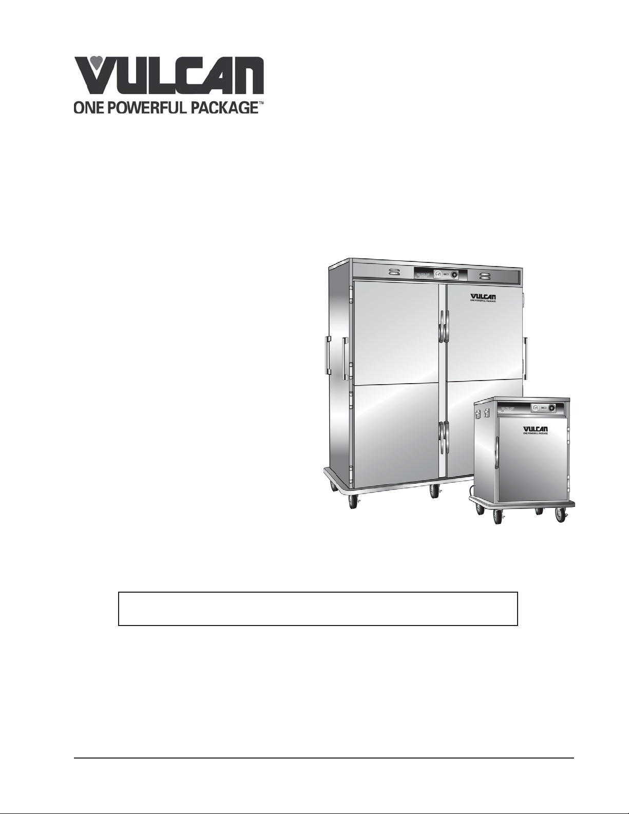
V SERIES FOOD HOLDING AND
TRANSPORTATION CABINETS
AND BANQUET CARTS
MODELS
INSTALLATION &
OPERATION MANUAL
VHP3 ML-126343
VHP7 ML-126344
VHP8 ML-126345
VHP15 ML-126346
VHP20 ML-126347
VBP5IML-138030
VBP7IML-126358
VBP13IML-126359
VBP15IML-126360
VBP77IML-126361
For additional information on Vulcan-Hart or to locate an authorized parts
and service provider in your area, visit our website at www.vulcanhart.com
VBS7 ML-138032
VBS15 ML-138033
VHDP5 ML-138035
VDW3 ML-138036
VB90 ML-126548
VB96 ML-126550
VB150 ML-126552
VB200 ML-138034
VULCAN-HART
DIVISION OF ITW FOOD EQUIPMENT GROUP, LLC
WWW.VULCANHART.COM
3600 NORTH POINT BLVD.
BALTIMORE, MD 21222
(9-07)
Page 2

V SERIES
IMPORTANT FOR YOUR SAFETY
THIS MANUAL HAS BEEN PREPARED FOR PERSONNEL QUALIFIED TO
INSTALL ELECTRICAL EQUIPMENT, WHO SHOULD PERFORM THE INITIAL
FIELD START-UP AND ADJUSTMENTS OF THE EQUIPMENT COVERED BY THIS
MANUAL.
FOR YOUR SAFETY
DO NOT STORE OR USE GASOLINE OR OTHER
FLAMMABLE VAPORS OR LIQUIDS IN THE VICINITY
OF THIS OR ANY OTHER APPLIANCE.
WARNING
IMPROPER INSTALLATION, ADJUSTMENT, ALTERATION, SERVICE OR MAINTENANCE CAN CAUSE
PROPERTY DAMAGE, INJURY OR DEATH. READ THE
INSTALLATION, OPERATING AND MAINTENANCE
INSTRUCTIONS THOROUGHLY BEFORE INSTALLING
OR SERVICING THIS EQUIPMENT.
IN THE EVENT OF A POWER FAILURE,
DO NOT ATTEMPT TO OPERATE THIS DEVICE.
— 2 —
Page 3
V SERIES
INSTALLATION, OPERATION AND CARE
V SERIES FOOD HOLDING AND TRANSPORTATION
CABINETS AND BANQUET CARTS
SAVE THESE INSTRUCTIONS FOR
FUTURE USE
Vulcan-Hart Holding and Transport Cabinets
and Banquet Carts are produced with quality
workmanship and material. Proper
installation, usage, and maintenance of your
cabinet will result in many years of satisfactory
performance.
It is suggested that you thoroughly read this
entire manual and carefully follow all of the
instructions provided.
The VBP series Holding and Transport
Cabinets provide an efficient means of
transporting and holding bulk prepared foods
at proper serving temperatures.
POWER
INDICATOR
LIGHT
170
160
180
150
140
120
40
100
80
60
20
190
70
80
60
50
20
0
200
90
100
210
NSF
®
105
220
°C
°F
THERMOMETER
POWER/HEAT
FULL RANGE
THERMOSTAT
3
2
1
HEAT
INDICATOR
LIGHT
5
6
4
7
8
9
10
OFF
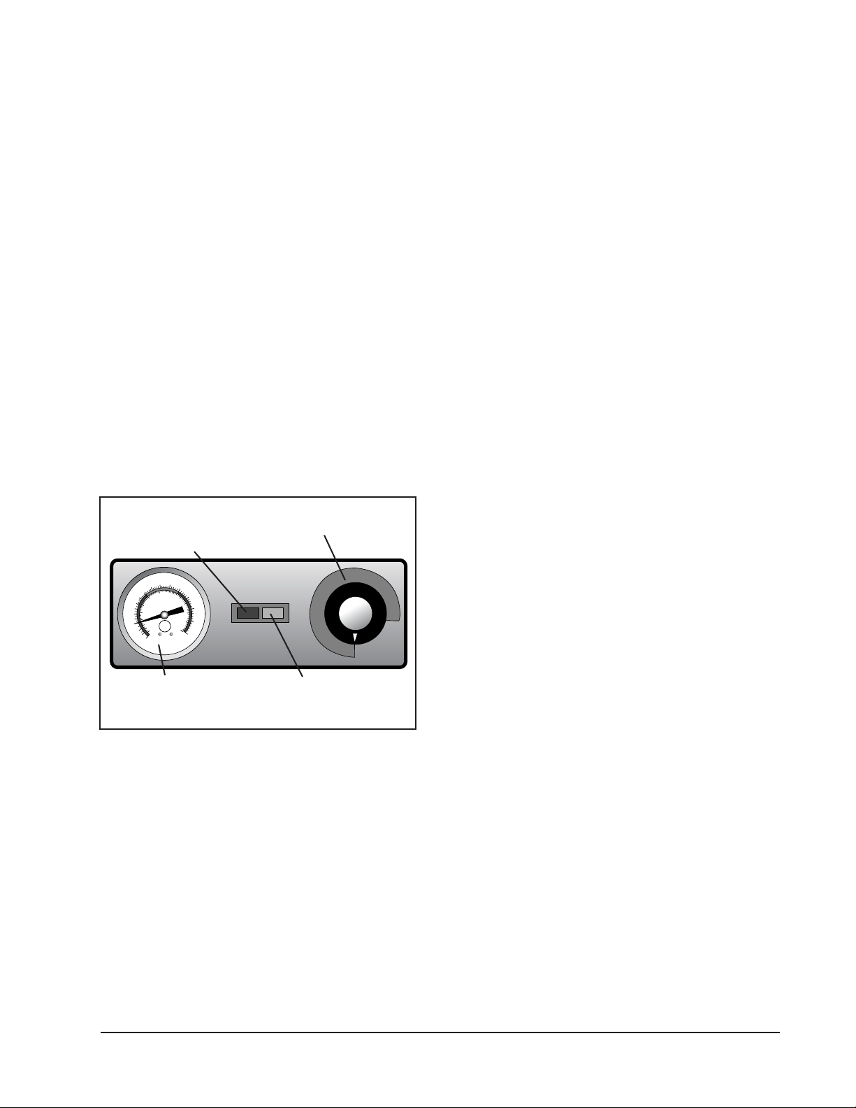
Fig. 1
Model VBP77I cabinets have individual
controls (Fig. 1) for each of the two
compartments. The operator is able to hold
two different products at two different
temperatures in separate sections of the same
cabinet.
All VBP Model, cabinets accommodate either
a third, half, or full size steam table pans of
various depths. The cabinets will also
accommodate the 1/1 or 2/1 gastronorm pan.
Model VHP Holding and Transport Cabinets
provide an efficient means of transporting,
holding, displaying, and serving a variety of
prepared foods at proper serving
temperatures.
All VHP Model, cabinets accommodate either
a third, half, or full size steam table pans of
various depths. The cabinets will also
accommodate the 1/1 gastronorm pan.
Model VB Banquet Carts provide an efficient
and sanitary method of holding and
transporting pre-plated food products in a
banquet facility. The carts are designed to
accommodate covered or uncovered plates.
The covered plates can be used with or without
plate carriers. The uncovered plates require
the use of plate carriers. Each cart is designed
to hold 10 ½″ (27 cm) plates. If larger or
smaller plates are used the capacities increase
or decrease to fit.
— 3 —
Page 4
V SERIES
INSTALLATION
Before installing, verify the electrical service
agrees with the specifications on the rating
plate located on the lower rear of the cart. If
the electrical service does not agree with the
rating plate, do not proceed with installation.
Contact your dealer or local Vulcan-Hart
service technician immediately.
Fig. 2
UNPACKING
The APPLIANCE was inspected before leaving
the factory. The transportation company
assumes full responsibility for safe delivery
upon acceptance of the shipment.
Immediately after unpacking, check for
possible shipping damage. If the APPLIANCE
is damaged, save packing material and
contact the carrier within 15 days of delivery.
Check the delivery documentation for damage
reporting contacts and time limits.
4. On food holding and transport cabinets,
remove cardboard element cover
protector from cabinet bottom.
Remove adjustable tray slides from box.
Remove the tray slide supports and
install them in the cabinet.
a. Hook the openings in the flat flange of
the support over two vertical carriage
bolts on the interior of the cabinet.
b. Make sure all flanges on the four
supports face the door opening.
Install tray slides in the cabinet.
Make sure the hook on the end of the
tray slide is up.
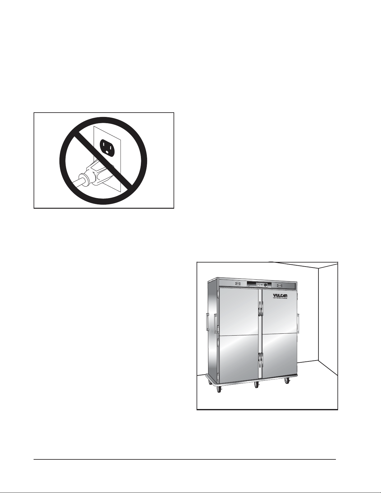
LOCATION
For efficient cabinet operation, choose a
location that will provide easy loading and
unloading without interfering with the final
assembly of food orders.
1
7
0
0
6
1
5
1
0
6
5
80
4
1
40
1
7
1
3
9
7
0
0
8
0
0
60
8
2
2
1
5
0
2
9
0
0
0
0
0
40
9
1
1
HOLDING AND
8
1
0
0
0
0
2
0
1
1
0
N
S
F
2
®
1
0
5
0
6
0
TRANSPORT
P
O
W
E
0
R/
H
E
AT
2
°
C
2
20
°
F
SYSTEM
O
FF
Carefully unpack and place in a workaccessible area as near the installation
position as possible.
1. Open the door and carefully remove any
packaging materials and the retaining
straps that hold the wire plate racks
(VB) or tray slides and tray slide upright
side supports (VBP/VHP).
2. Remove all scratch protective film from
the cabinet.
3. On banquet carts, lift the plate racks
into position on the side brackets.
Leave adequate clearance
for ease of loading and unloading.
Fig. 3
The installation location must allow adequate
clearances for servicing and proper operation.
— 4 —
Page 5

V SERIES
INSTALLATION CODES AND
STANDARDS
The APPLIANCE must be installed in
accordance with:
In the United States of America:
1. State and local codes.
2. National Electrical Code, ANSI/NFPA-70
(latest edition). Copies may be obtained
from The National Fire Protection
Association, Batterymarch Park, Quincy,
MA 02269.
In Canada:
1. Local codes.
2. Canadian Electrical Code, CSA C22.1
(latest edition). Copies may be obtained
from The Canadian Standard
Association, 178 Rexdale Blvd.,
Etobicoke, Ontario, Canada M9W 1R3.
ELECTRICAL CONNECTIONS
Electrical and grounding
connections must comply with the
applicable portions ofthe National
Electrical code and/or other local electrical
codes.
The cord and plug supplied, is a suitable
durable cord with molded plug and is provided
with a proper strain relief.
Appliances equipped with
a flexible electric supply cord provided
with a three-prong grounding plug. It is
imperative that this plug be connected
into a properly grounded three-prong
receptacle. If the receptacle is not the
proper grounding type, contact an
electrician. Do Not remove the grounding
prong from this plug.
Refer to wiring diagrams in this manual.
All cabinets are equipped with an 8 ft. (2.4 m)
cord and NEMA 5-15 plug as standard
equipment.
The banquet cart series are factory wired for
either 110/120 volt or 208/240 volt, single
phase operation.
• All 208/240 volt carts are equipped
with an 8 ft. (2.4 m) cord and NEMA
6-15 plug.
— 5 —
Page 6
V SERIES
Electrical Connection
Electrical and grounding
connections must comply with the
applicable portions of the National
Electrical Code and/or other Local
Electrical Codes.
electrical power to the
machine and follow Lockout/
Tagout procedures before
cleaning.
Disconnect
MODEL VOLTAGE AMP PHASE HZ NEMA PLUG
VBP5I, VBP7I, VBP13I, 110/120 10 1 60 5-15
VBP15I, VBS7, VBS15, 208/240 5.4 6-15
VHDP5, VDW3
VBP77I 110/120 20 1 60 5-20
208/240 10.9 6-20
VHP3, VHP7, VHP8 110/120 5 1 60 5-15
208/240 2.7 6-15
VHP15, VHP20 110/120 10 1 60 5-15
208/240 5.4 6-15
VB90, VB96, 110/120 16.6 1 60 5-20
VB150, VB200 208/240 9.0 6-20
— 6 —
Page 7

OPERATION
V SERIES
The cabinet and its parts
are hot, be very careful when operating,
cleaning or servicing the cabinet.
CONTROLS
POWER
INDICATOR
LIGHT
170
160
180
150
140
120
40
100
80
60
20
190
70
80
60
50
20
0
200
90
100
210
NSF
®
105
220
°C
°F
THERMOMETER
POWER/HEAT
FULL RANGE
THERMOSTAT
3
2
1
HEAT
INDICATOR
LIGHT
5
6
4
7
8
9
10
OFF
Fig. 4
HOLDING COMPARTMENTS
BEFORE FIRST USE
Disconnect
electrical power to the
machine and follow Lockout/
Tagout procedures before
cleaning.
POWER INDICATOR LIGHT
Lit when power is supplied to cabinet.
HEAT INDICATOR LIGHT
Lit when heat is supplied to cabinet.
FULL RANGE THERMOSTAT
Turn to desired temperature setting (1-10).
THERMOMETER
Indicates interior temperature.
Fig. 5
1. Clean appliance thoroughly.
a. Use mild soap and water solution to
clean appliance.
b. Wipe dry with a soft clean cloth.
c. Clean all accessories.
2. Operate appliance in highest
temperature setting for a period of 30-45
minutes. (See Operating Instructions).
— 7 —
Page 8

V SERIES
PO
NSF
®
°F
20
60
80
100
120
140
150
160
170
180
190
200
210
220
0
20
40
50
60
70
80
90
100
105
°C
OPERATING APPLIANCE
1. Connect electric power supply.
• Power indicator light is lit.
Fig. 6
2. Turn thermostat knob to desired setting.
• Heating elements begin heating.
Fig. 8
4. Once desired temperature is reached,
heating elements will cycle on and off.
• Heat light(s) will cycle on and off with
the heating elements.
5. Temperature in heated appliance will
fluctuate as the heating elements cycle
on and off.
6. Monitor the food product to ensure
proper temperatures.
• Heat indicator light is lit.
5
4
3
2
1
6
7
8
9
10
AT
OFF
Fig. 7
3. Thermometer will indicate the interior
temperature of the appliance.
Appliance Temperatures
The greater the thermostat setting number,
the higher the appliance temperature. The
lower the thermostat setting number, the lower
the appliance temperature.
Thermostat Setting Approximate
Temperature
1 110°F (43°C)
2 120°F (49°C)
3 130°F (54°C)
4 140°F (60°C)
5 150°F (66°C)
6 160°F (71°C)
7 170°F (77°C)
8 180°F (82°C)
9 190°F (88°C)
10 200°F (93°C)
— 8 —
Page 9

V SERIES
Shutdown
Turn full range thermostat counterclockwise
to OFF.
5
4
3
2
1
6
7
8
9
10
AT
OFF
Fig. 9
Unplug electrical power supply. Power
indicator light will go off.
CLEANING
Disconnect
electrical power to the
machine and follow Lockout/
Tagout procedures before
cleaning.
Clean appliance interior with mild soap and
water whenever a food spill occurs. Never use
harsh chemicals or abrasive pads to clean
appliance.
Daily
1. Allow appliance to cool before cleaning.
2. Remove tray slides or plate racks and
clean in a sink as you would any utensil.
3. Clean the interior of the appliance with
mild soap and water.
Fig. 10
Extended Shutdown
Unplug electrical power supply. Power
indicator light will go off.
4. Place tray slides or plate racks in the
appliance.
— 9 —
Page 10

V SERIES
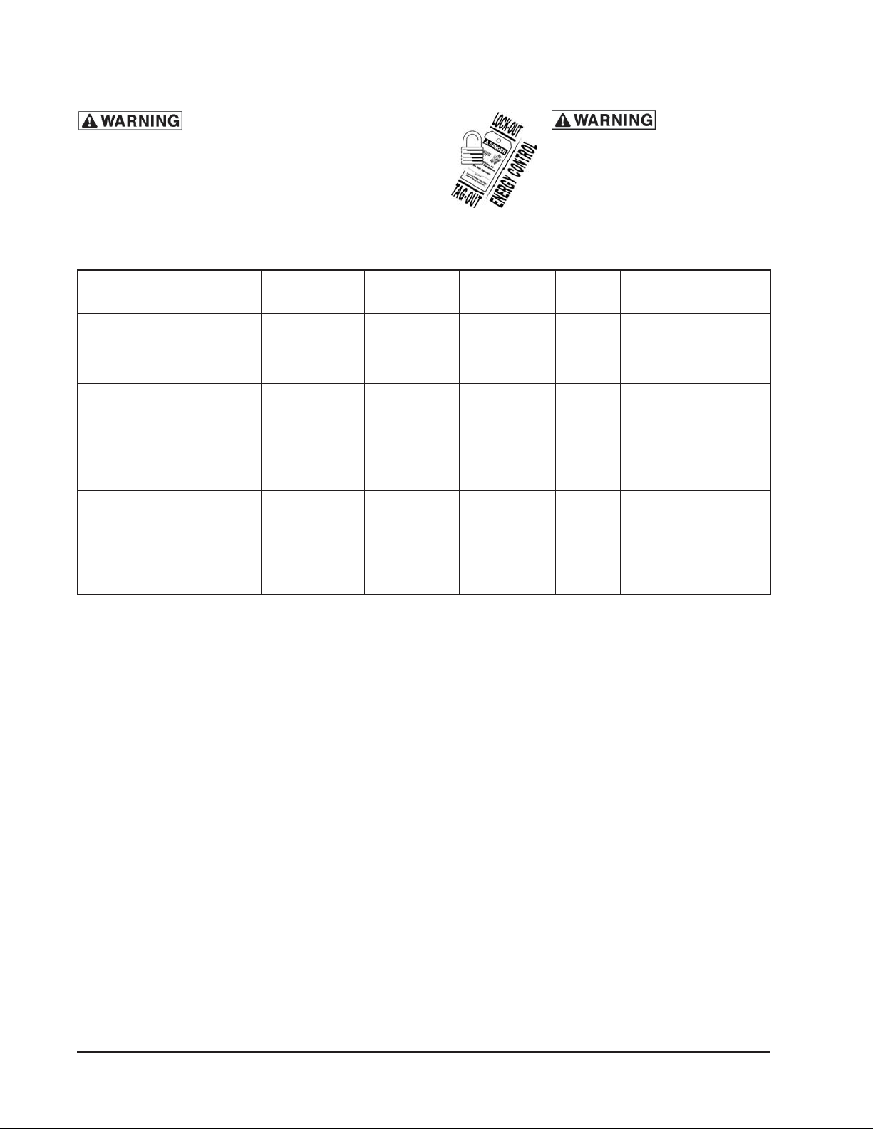
TROUBLESHOOTING
SYMPTOMS POSSIBLE CAUSES REMEDY
Temperature incorrect No main power source Check the power source or circuit breaker.
Power switch in off position Press power switch to the on position.
Door open Close door.
Door leaks Damaged door gasket Check door gasket for damage.
If adjustment is needed, contact your
Authorized Vulcan-Hart Servicer.
Compartment does Defective heating coil Contact your authorized service provider.
not heat properly
Defective thermostat or Contact your authorized service provider.
thermostat requires
adjustment
Indicator lights not lit
Power indicator light No power to appliance Check power source.
Heat indicator light No heat Check power source and thermostat
operation.
— 10 —
Page 11

WIRING DIAGRAMS
V SERIES
THERMOSTAT
BLACK
POWER
CONNECTION
120V, 1PH, 60 Hz
208/240V, 1PH, 60 Hz
BLACK
WHITE WHITE
GREEN
RED
POWER
A
A
HEATING
ELEMENT
POWER
R
HEATING
ELEMENT
VB48, VB72, VB90, VB96, VB150, VBP5I, VBP7I, VBP13I, VBP15I, VHP15, VHP20
Wiring Diagram
— 11 —
Page 12

V SERIES
POWER
CONNECTION
120V, 1PH, 60 Hz
208/240V, 1PH, 60 Hz
BLACK
WHITE
GREEN
BLACK
THERMOSTAT
HEATING
ELEMENT
BLACK
POWER
R
POWER
R
POWER
A
POWER
A
THERMOSTAT
HEATING
ELEMENT
VBP77I Wiring Diagram
— 12 —
Page 13

POWER
CONNECTION
120V, 1PH, 60 Hz
208/240V, 1PH, 60 Hz
POWER
THERMOSTAT
RED
BLACK
WHITE WHITE
GREEN
V SERIES
A
A
HEATING
ELEMENT
VHP3, VHP7, VHP8 Wiring Diagram
— 13 —
Page 14

V SERIES
VULCAN REPLACEMENT PARTS LIST
BOLT, RETAINING RACK (PACK OF 4) WP-305 851800-26
CAP, CHROME INSPECTION WP-174 851800-23
CLIP, ELEMENT WP-182 851800-14
CORD, POWER 12/3 120V. 15 AMP WP-015-1 851800-99
CORD, POWER 12/3 120V. 20 AMP WP-247 851800-148
CORD, POWER 12/3 208/240V. 15 AMP WP-015-2 851800-213
CORD, POWER 16/3 120V. WP-052 851800-6
ELEMENT, 120V – 1000W WP-105-1 851800-151
ELEMENT, 120V – 600W (1220/1826) WP-104-1 851800-11
ELEMENT, 208/240V – 600W (1220/1826) WP-104-2 851800-13
ELEMENT, 208/240V – 1000W (1826-40) WP-105-2 851800-152
GASKET, DOOR WP-302 851800-17
HANDLE, PUSH/PULL WP-117 851800-132
HANDLE, PUSH/PULL S.S. (2026 SERIES) WP-236 851800-223
HANDLE, PUSH/PULL S.S. (2-90 ONLY) WP-237 851800-375
HANDLE, PUSH/PULL S.S. (ALL EXCEPT 2-90) WP-149 851800-606
HANDLE, SIDE LIFT (1220-3, 7, 8/1826-7) WP-108 851800-134
HINGE, DOOR WP-111 851800-18
HOLDER, PROBE THERMOMETER WP-093 851800-29
HOLDER, PROBE THERMOSTAT WP-089 851800-32
KNOB, THERMOSTAT WP-242 851800-31
LATCH, DOOR WP-107 851800-8
LATCH, DOOR (MAGNETIC) WP-372 851800-626
LIGHT, INDICATOR DUAL 125V WP-106-1 851800-21
LIGHT, INDICATOR DUAL 240V WP-106-2 851800-22
PAN, HUMIDITY W/SPONGE WP-103 851800-135
PLATE, CARRIER, WIRE (COVERED) WP-126 851800-465
PLATE, CARRIER, WIRE (UNCOVERED) WP-127 851800-466
RACK, WIRE SHELF (2-150) WP-123-150 851800-408
RACK, WIRE SHELF (2-72) WP-123-72 851800-405
RACK, WIRE SHELF (2-90) WP-123-90 851800-406
RACK, WIRE SHELF (2-96) WP-123-96
SLIDES, TRAY METRIC (EACH) WP-291 851800-310
SPONGE, HUMIDITY WP-099 851800-20
STRAIN RELIEF, 12/3 POWER CORD WP-006-312 851800-229
STRAIN RELIEF, 16/3 POWER CORD WP-006-1 851800-7
THERMOMETER, DIAL WP-109 851800-28
THERMOSTAT WP-110 851800-30
851800-407
— 14 —
Page 15

NOTES
V SERIES
(9-07)
— 15 —
PRINTED IN U.S.A.
Page 16

V SERIES
SERVICE AND PARTS INFORMATION
To obtain service and parts information concerning this model, contact the Vulcan-Hart Service
Agency in your area (refer to our website, www.vulcanhart.com for a complete listing of Authorized
Service and Parts depots).
When calling for service, the following information must be available: model number, serial number,
manufacture date (MD) and voltage.
— 16 —
 Loading...