

Page 1

SERVICE MANUAL
V Series Heated Holding
Insulated Cabinets
VBP5 ML-138030
VBP7 ML-126358
VBP13 ML-126359
VBP15 ML-126360
VBP18
VHP7 ML-126344
VHP15 ML-126346
VPT7
VPT13
VPT15
VPT18
- NOTICE -
This Manual is prepared for the use of trained Vulcan Service
Technicians and should not be used by those not properly
qualified.
This manual is not intended to be all encompassing. If you have
not attended a Vulcan Service School for this product, you should
read, in its entirety, the repair procedure you wish to perform to
determine if you have the necessary tools, instruments and skills
required to perform the procedure. Procedures for which you do
not have the necessary tools, instruments and skills should be
performed by a trained Vulcan Service Technician.
The reproduction, transfer, sale or other use of this Manual,
without the express written consent of Vulcan, is prohibited.
This manual has been provided to you by ITW Food Equipment
Group LLC ("ITW FEG") without charge and remains the property
of ITW FEG, and by accepting this manual you agree that you will
return it to ITW FEG promptly upon its request for such return at
any time in the future.
A product of Vulcan-Hart 3600 North Point Blvd Baltimore, MD 21222
F45748 (0219)
Page 2

V Series Heated Holding Insulated Cabinets
TABLE OF CONTENTS
SERVICE UPDATES ....................................................................................... 3
SERVICE UPDATES ................................................................................... 3
TIS DOCUMENT LIST - V SERIES HEATED HOLDING INSULATED CABINETS ......................... 3
GENERAL .................................................................................................. 4
INTRODUCTION ....................................................................................... 4
INSTALLATION, OPERATION AND CLEANING ......................................................... 4
TOOLS ................................................................................................. 4
SPECIFICATIONS ...................................................................................... 4
DATA PLATE LOCATIONS ............................................................................. 4
REMOVAL AND REPLACEMENT OF PARTS ............................................................... 5
TOP COVER ........................................................................................... 5
FOOD COMPARTMENT FAN ........................................................................... 5
HEATING ELEMENTS .................................................................................. 6
POWER CORD ......................................................................................... 7
HIGH LIMIT SWITCH ................................................................................... 8
TERMINAL BLOCK ..................................................................................... 8
TEMPERATURE PROBE ............................................................................... 8
COMPONENT COOLING FAN .......................................................................... 9
CONTROL BOARD ..................................................................................... 9
DOOR GASKET ....................................................................................... 11
DOOR ASSEMBLY .................................................................................... 11
DOOR LATCH (MAGNETIC) ........................................................................... 12
SERVICE PROCEDURES AND ADJUSTMENTS ........................................................... 14
TEMPERATURE VERIFICATION ...................................................................... 14
HEATER ELEMENT TEST ............................................................................. 14
ELECTRICAL OPERATION ................................................................................ 15
COMPONENT DESCRIPTIONS ....................................................................... 15
WIRING DIAGRAM .................................................................................... 16
SEQUENCE OF OPERATION ......................................................................... 16
TROUBLESHOOTING ................................................................................. 17
© VULCAN 2019
F45748 (0219) Page 2 of 17
Page 3
V Series Heated Holding Insulated Cabinets - SERVICE UPDATES
SERVICE UPDATES
SERVICE UPDATES
JANUARY 2019
• New service manual release.
TIS DOCUMENT LIST - V SERIES HEATED HOLDING INSULATED CABINETS
SERVICE TAB
Document Title Document Type
V Series Heated Holding Transportation Cabinets Service Manual
SERVICE MULTIMEDIA TAB
Document Title Document Type
V Series Heated Holding Transportation Cabinets Installation &
Operation
V Series Heated Holding Transportation Cabinets Specifications Specification
Operators Manual
PARTS TAB
Document Title Document Type
V Series Heated Holding Transportation Cabinets Parts Catalog
Page 3 of 17 F45748 (0219)
Page 4
V Series Heated Holding Insulated Cabinets - GENERAL
GENERAL
INTRODUCTION
This manual is applicable only to models listed on the
cover page. Procedures in this manual will apply to all
models unless specified. Pictures and illustrations can
be of any model unless they need to be model specific.
INSTALLATION, OPERATION AND
CLEANING
For detailed installation, operation and cleaning
instructions, refer to the Installation & Operation
Manual sent with each unit. The manual is also
available online at www.vulcanequipment.com.
TOOLS
Standard
• Standard set of hand tools.
• VOM with minimum of NFPA-70E CATIII 600V,
UL/CSA/TUV listed. Sensitivity of at least 20,000
ohms per volt and the ability to measure DC
micro amps. Meter leads must also be rated at
CAT III 600V.
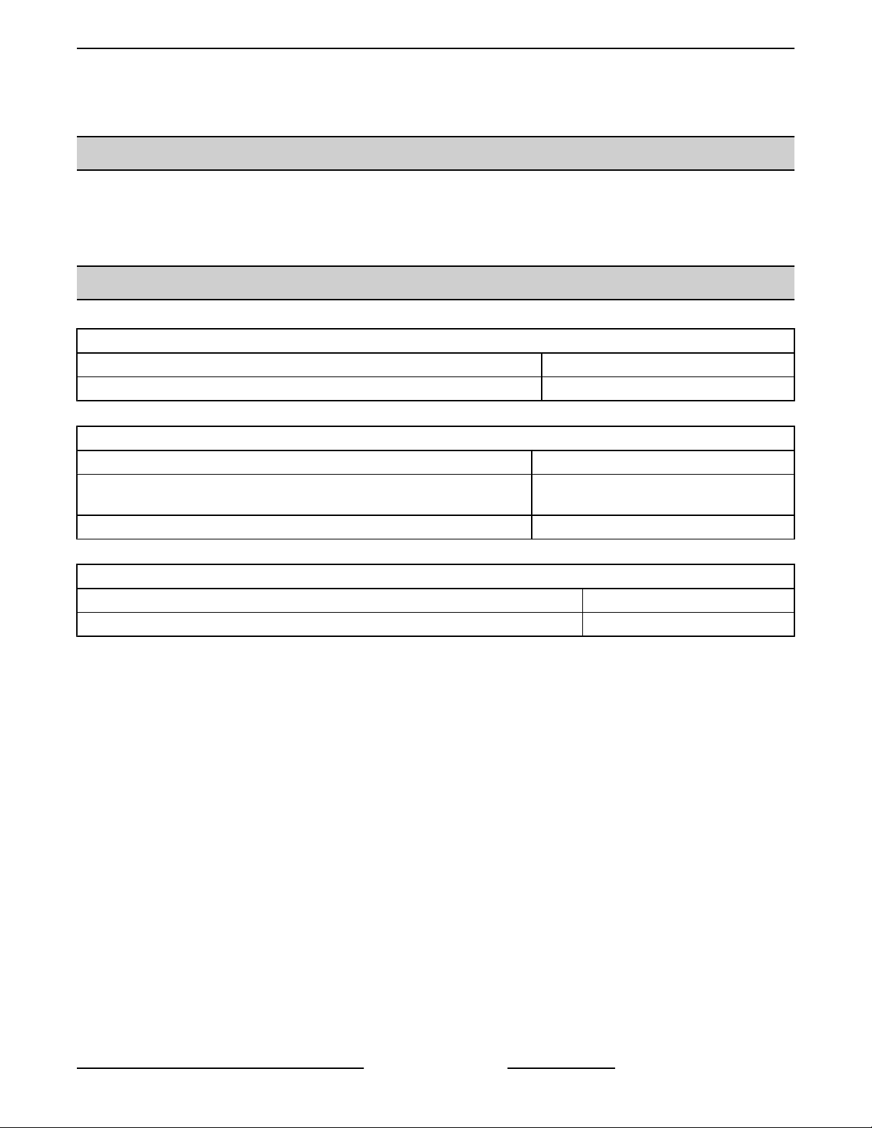
DATA PLATE LOCATIONS
DATA PLATE LOCATED ON BACK PANEL
• Clamp on type amp meter with minimum of
NFPA-70E CAT III 600V,UL/CSA/TUV listed.
• Temperature tester (thermocouple type).
• ESD (Electrostatic discharge) Protection Kit.
Special
• Handheld, digital temperature and humidity
sensor Grainger No. 3LYH7 or equivalent.
SPECIFICATIONS
MODELS VOLTS WATTS AMPS
VBP and
VPT
120V 1,500 12.5
240V 1,500 6.25
INSIDE DATA PLATE
F45748 (0219) Page 4 of 17
Page 5
V Series Heated Holding Insulated Cabinets - REMOVAL AND REPLACEMENT OF PARTS
REMOVAL AND REPLACEMENT OF PARTS
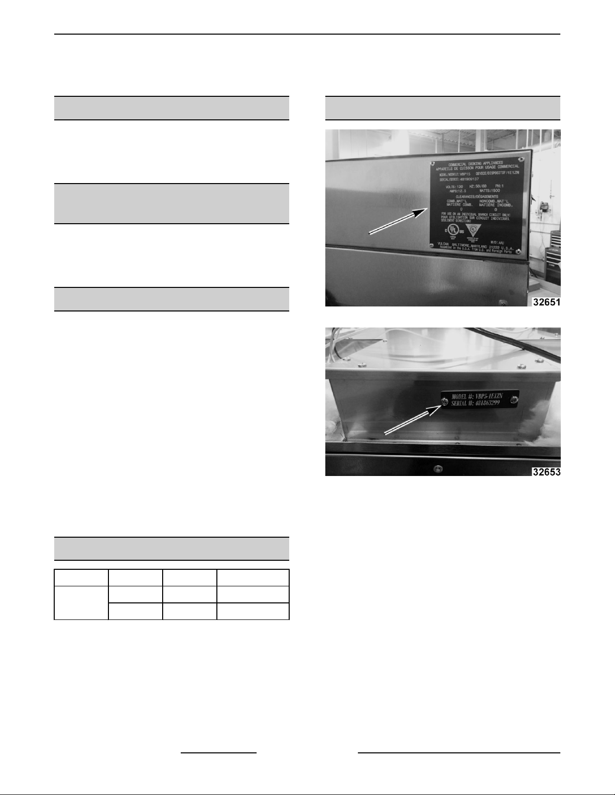
TOP COVER
Disconnect the electrical power to
the machine and follow lockout /
tagout procedures.
NOTE: Remove top cover to access power cord,
cooling fan, and control board.
1. Remove screws from top and side of top cover.
2. Remove insulation (1, Fig. 5).
Fig. 5
3. Note and disconnect wiring from terminal block
and control board.
4. Remove inside access cover (1, Fig. 6).
Fig. 3
Fig. 4
2. Lift cover off cabinet.
3. Reverse procedure to install.
FOOD COMPARTMENT FAN
Disconnect the electrical power to
the machine and follow lockout /
tagout procedures.
Fig. 6
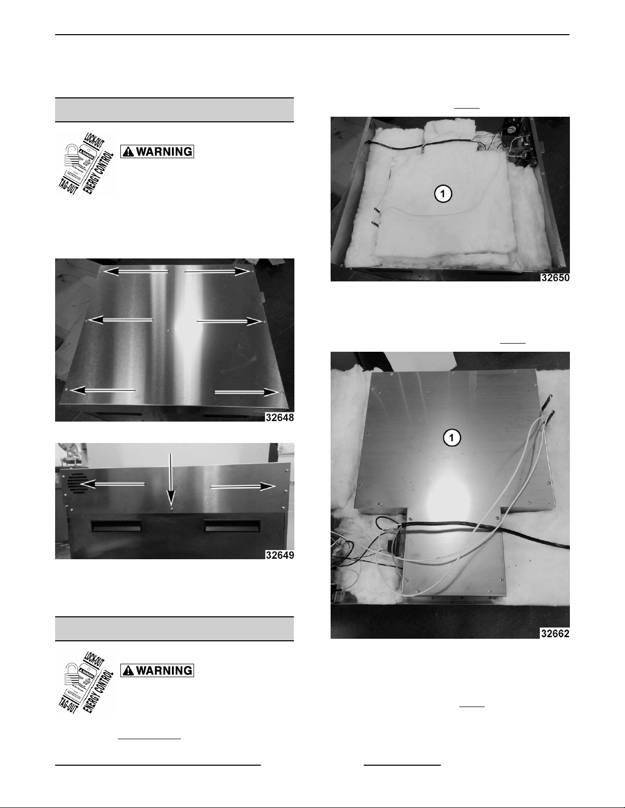
5. Remove fan mounting bracket.
6. Remove screws from fan.
7. Install fan with label (1, Fig. 7) up.
1. Remove TOP COVER .
Page 5 of 17 F45748 (0219)
Page 6
V Series Heated Holding Insulated Cabinets - REMOVAL AND REPLACEMENT OF PARTS
Fig. 7
8. Reverse procedure to install.
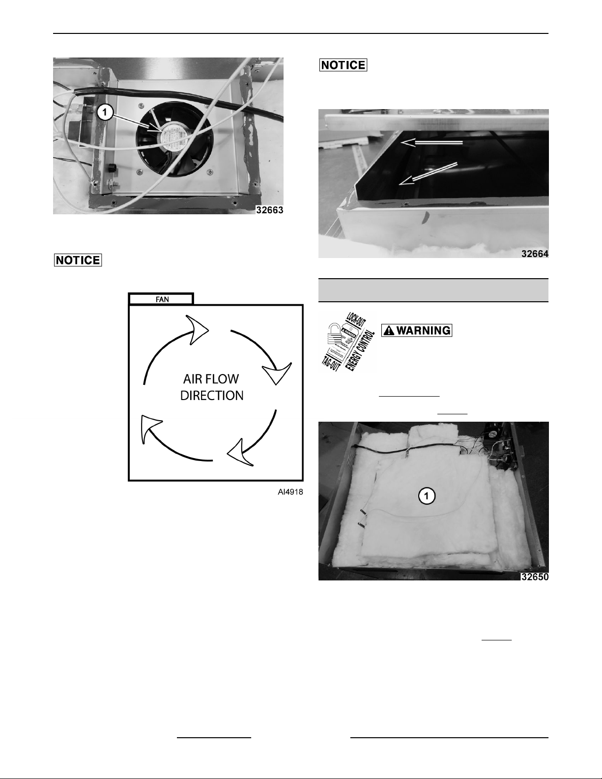
Verify air flow direction in cavity.
When installing inside access cover, verify edge
inserts into slot without catching.
Fig. 9
HEATING ELEMENTS
Fig. 8
Disconnect the electrical power to
the machine and follow lockout /
tagout procedures.
1. Remove TOP COVER .
2. Remove insulation (1, Fig. 10).
Fig. 10
3. Note and disconnect wires from terminal block
and control board.
4. Remove inside access cover (1, Fig. 11).
F45748 (0219) Page 6 of 17
Page 7

V Series Heated Holding Insulated Cabinets - REMOVAL AND REPLACEMENT OF PARTS
When installing inside access cover, verify edge
inserts into slot without catching.
Fig. 13
POWER CORD
Fig. 11
5. Remove heating element mounting screws.
Fig. 12
6. Reverse procedure to install.
Disconnect the electrical power to
the machine and follow lockout /
tagout procedures.
1. Remove TOP COVER .
2. Note and disconnect wiring from terminal block
and high limit.
3. Squeeze cord grip to remove from panel.
Fig. 14
4. Reverse procedure to install.
Page 7 of 17 F45748 (0219)
Page 8

V Series Heated Holding Insulated Cabinets - REMOVAL AND REPLACEMENT OF PARTS
HIGH LIMIT SWITCH
Disconnect the electrical power to
the machine and follow lockout /
tagout procedures.
1. Remove TOP COVER .
2. Note and disconnect wiring.
3. Remove mounting screws for high limit switch (1,
Fig. 15).
Fig. 16
4. Reverse procedure to install.
TEMPERATURE PROBE
Fig. 15
4. Reverse procedure to install.
TERMINAL BLOCK
Disconnect the electrical power to
the machine and follow lockout /
tagout procedures.
1. Remove TOP COVER .
2. Note and disconnect wiring.
3. Remove terminal block (1, Fig. 16) mounting
screws.
Disconnect the electrical power to
the machine and follow lockout /
tagout procedures.
1. Remove TOP COVER .
2. Disconnect temperature probe at control board
connection.
3. Open door.
4. Pull temperature probe out from holder on cavity
ceiling.
5. Pull probe (1, Fig. 18) up through grommet in top
F45748 (0219) Page 8 of 17
Fig. 17
of cabinet.
Page 9

V Series Heated Holding Insulated Cabinets - REMOVAL AND REPLACEMENT OF PARTS
Fig. 18
6. Reverse procedure to install.
COMPONENT COOLING FAN
Note air flow direction on fan when replacing fan. (1,
Rotation
Fig. 20) (2, Air Flow Fig. 20)
Disconnect the electrical power to
the machine and follow lockout /
tagout procedures.
1. Remove TOP COVER .
2. Note and disconnect fan wiring to terminal block
and control board.
3. Remove fan mounting screws.
Fig. 19
Fig. 20
4. Reverse procedure to install.
CONTROL BOARD
Disconnect the electrical power to
the machine and follow lockout /
tagout procedures.
Certain components in this system are subject to
damage by electrostatic discharge (ESD) during field
repairs. An ESD kit is required to prevent damage. The
ESD kit must be used anytime the circuit board is
handled.
1. Remove TOP COVER .
2. Note and disconnect board connectors and
wires.
Page 9 of 17 F45748 (0219)
Page 10

V Series Heated Holding Insulated Cabinets - REMOVAL AND REPLACEMENT OF PARTS
Fig. 21
3. Remove "optional" knob cover if applicable
(VBP5 and VBP7).
Fig. 22
4. Remove retaining screw in knob.
Fig. 24
5. Remove potentiometer retaining nut.
Fig. 25
6. Remove control board mounting nuts.
Fig. 23
F45748 (0219) Page 10 of 17
7. Remove board.
8. Reverse procedure to install.
Fig. 26
Page 11

V Series Heated Holding Insulated Cabinets - REMOVAL AND REPLACEMENT OF PARTS
DOOR GASKET
NOTE: Measure gasket before ordering replacement.
Gasket is a separate component from retainer and
should be ordered separately from retainer.
1. Open door.
2. Unscrew gasket retainers.
Fig. 29
5. Install retainer with flat side against cavity wall
and channel toward inside of cabinet.
DOOR ASSEMBLY
1. Remove door hinge covers (1, Fig. 30) from lower
and upper door hinge.
Fig. 27
3. Remove gasket (1, Fig. 28) from retainer (2, Fig.
28).
Fig. 28
4. Press gasket on retainer while aligning channel.
Page 11 of 17 F45748 (0219)
Fig. 30
Remain in control of door when removing hinges.
2. Remove door hinge inside mounting screws
from lower door hinge first.
Page 12

V Series Heated Holding Insulated Cabinets - REMOVAL AND REPLACEMENT OF PARTS
Fig. 31
3. Remove door hinge inside mounting screws from
upper door hinge while supporting door weight.
4. Lift door assembly from cabinet.
5. Reverse procedure to install.
6. Check for proper operation.
DOOR LATCH (MAGNETIC)
NOTE: Note orientation of door handle before
removal.
Fig. 32
F45748 (0219) Page 12 of 17
Page 13

V Series Heated Holding Insulated Cabinets - REMOVAL AND REPLACEMENT OF PARTS
Install handle in the same orientation it was removed.
4. Check for proper operation.
Fig. 33
1. Open door.
2. Remove screws securing door latch to door
assembly.
Fig. 34
3. Reverse procedure to install.
Page 13 of 17 F45748 (0219)
Page 14

V Series Heated Holding Insulated Cabinets - SERVICE PROCEDURES AND ADJUSTMENTS
SERVICE PROCEDURES AND ADJUSTMENTS
TEMPERATURE VERIFICATION
The warmer and its parts are hot. Use care when
operating, cleaning or servicing the oven.
NOTE: Units prior to 1/1/15 can be calibrated, counter
clockwise to increase and clockwise to decrease.
Screw is located inside stem on the mechanical
thermostat. quarter turn is five degrees. Units after
1/1/15 can not be calibrated.
1. Check room temperature.
2. Place temperature probe at the center of the
cabinet.
3. Set unit temperature to 145°F.
4. Wait 45 minutes.
5. The temperature setting should be between 138
- 152F°.
VERIFY
• When using cabinet, frequently opening the
door will affect average internal
temperature. Modify set temperature as
necessary to ensure product is held above
appropriate food safe temperature.
Heating Elements
Model Wattage Voltage Resistance
all VBP
NOTE: If numbers do not match, replace HEATER
ELEMENTS.
1500 240 38.4 +/- 10 %
HEATER ELEMENT TEST
Certain procedures in this section
require electrical test or
measurements while power is
applied to the machine. Exercise
extreme caution at all times and
follow Arc Flash procedures. If test
points are not easily accessible,
disconnect power and follow
Lockout/Tagout procedures, attach
test equipment and reapply power to
test.
1. Access the heater element being tested. Refer
to: HEATER ELEMENTS.
2. Check resistance.
Heating Elements
Model Wattage Voltage Resistance
all VPT 1500 120 9.6 +/- 10 %
F45748 (0219) Page 14 of 17
Page 15

V Series Heated Holding Insulated Cabinets - ELECTRICAL OPERATION
ELECTRICAL OPERATION
COMPONENT DESCRIPTIONS
ITEM DESCRIPTION
Food Compartment Fan Circulates air inside the cabinet. Moisture resistant with metal fan blades.
Controller Board Controls the temperature, humidity and fan inside the cabinet.
Heating Element - Dry Heats the air to keep prepared food at the proper serving temperatures.
Component Cooling Fan Circulates air in the electrical component area.
High Limit High Limit opens at 375°F.
Page 15 of 17 F45748 (0219)
Page 16

V Series Heated Holding Insulated Cabinets - ELECTRICAL OPERATION
WIRING DIAGRAM
Fig. 35
SEQUENCE OF OPERATION
1. Conditions.
A.
Unit connected to correct voltage and is
properly grounded.
B. Power switch is off.
2. Power switch turned on.
A. Relays K1 and K2 are de-energized
(contacts N.O.).
B. Controller board performs diagnostic test
and verifies temperature input signal is
present.
F45748 (0219) Page 16 of 17
3. Fan relay K2 is energized, K2 contacts close and
4. Based on temperature and humidity settings, the
5. Adjust temperature to desired level.
6. Turning power switch off stops heating cycle.
power the fans.
board determines whether K1 relay will be
energized to power element.
Page 17

V Series Heated Holding Insulated Cabinets - ELECTRICAL OPERATION
TROUBLESHOOTING
Symptom Possible Cause
Cabinet not operating.
Ground Fault Circuit Indicator (GFCI)
tripped.
Cabinet connected to power, switch is
ON, circuit breaker is ON but cabinet not
heating.
1. Cabinet not connected to power source or circuit breaker tripped.
2. Cabinet lighted power switch not ON or malfunctioning.
1. Shorted heating element.
2. Pinched/damaged wiring (heating elements or fan).
3. Damaged power cord.
1. Heating element malfunction.
2. Temperature probe malfunction.
1. Element wires disconnected from element. Replace wire assembly
and element.
Cabinet not heating properly.
Fan not operating.
Moisture present at the top of the cabinet
near the control board.
Corrosion present inside cabinet.
2. FOOD COMPARTMENT FAN not circulating air or malfunction.
3. Door not sealing properly.
4. Temperature probe malfunction.
1. Power not being supplied to fan (malfunction).
2. Fan wiring not connected or malfunction.
3. Fan not circulating air or malfunction.
1. COMPONENT COOLING FAN malfunction.
1. Periodic cleaning needed. Refer to Operations manual.
2. Hardware has rusted. Replace rusted hardware with 18-8 stainless
steel components and replace FOOD COMPARTMENT FAN.
Page 17 of 17 F45748 (0219)
 Loading...