

Page 1
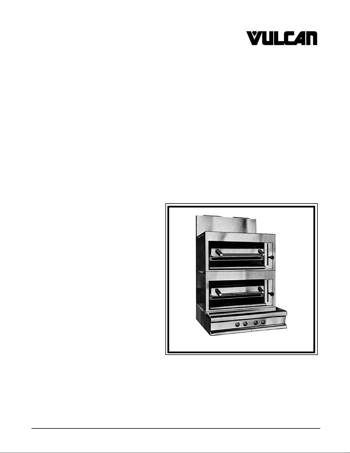
INSTALLATION &
OPERATION MANUAL
HEAVY DUTY ELECTRIC BROILER SERIES
MODELS
VB 21 ML-052312
VB 21C ML-052312
VB 25 ML-052313
VB 73 ML-052249
VB 221 ML-052315
VB 221C ML-052315
VB 225 ML-052316
VTMB 221 ML-052314
VTMB 221C ML-052314
VTMB22
VULCAN-HART COMPANY, P.O. BOX 696, LOUISVILLE, KY 40201-0696, TEL. (502) 778-2791
FORM 31065 (5-98)
Page 2

TABLE OF CONTENTS
GENERAL ......................................................................................................................................... 3
INSTALLATION .................................................................................................................................. 4
Unpacking ..................................................................................................................................... 4
Installation Codes and Standards ................................................................................................. 4
Location ......................................................................................................................................... 4
Electrical Connections ................................................................................................................... 4-5
Electrical Data Chart ..................................................................................................................... 5
Electrical Tests ............................................................................................................................... 6
Leveling ......................................................................................................................................... 6
OPERATION ....................................................................................................................................... 7
Controls ......................................................................................................................................... 7
Before First Use ............................................................................................................................ 8
Using the Broiler ............................................................................................................................ 8
Using the Oven .............................................................................................................................. 8-9
Time, Temperature & Switch Chart for Baking............................................................................... 10
Cleaning ........................................................................................................................................ 11
MAINTENANCE ................................................................................................................................. 12
Service and Parts Information ....................................................................................................... 12
– 2 –
Page 3

Installation, Operation and Care of
MODELS VTMB22, VTMB2, VB2S & VB21
HEAVY DUTY ELECTRIC BROILERS
KEEP THESE INSTRUCTIONS FOR FUTURE USE
GENERAL
Your Vulcan-Hart Heavy Duty Electric Broiler is produced with quality workmanship and material.
Proper installation, usage and maintenance of your broiler will result in many years of satisfactory
performance.
Vulcan-Hart Company suggests that you thoroughly read this entire manual and carefully follow all of
the instructions provided.
Model VB Ovens are provided with one rack as standard equipment.
MODEL DESCRIPTION
VB 21 Single section broiler with standard oven below
VB 25 Single section broiler with storage space below
VB 225 Double section broilers with storage space below
VTMB 2 Modular single section broiler
VTMB 22 Modular double section broiler
VB 73 Backshelf broiler for mounting over a 3-ft. (91 cm) range
VB 21C Single section broiler with convection oven below
VB 221 Double section broiler with standard oven below
VB 221C Double section broilers with convection oven below
– 3 –
Page 4

INSTALLATION
UNPACKING
Immediately after unpacking, check for possible shipping damage. If the broiler is found to be
damaged, save the packaging material and contact the carrier within 15 days of delivery.
Remove all shipping wire, wood blocking, and accessories.
Before installing, verify that the electrical service agrees with the specifications on the rating plate
located as follows: VTMB units - on the control panel front; VB21 - behind the oven door on the breaker
box cover; and VB2S - behind the door panel of the storage cabinet base. If the supply and equipment
requirements do not agree, contact your dealer or Vulcan-Hart immediately.
INSTALLATION CODES AND STANDARDS
Your Vulcan broiler must be installed in accordance with:
1. State and local codes, or in the absence of local codes, with:
2. National Electrical Code ANSI/NFPA-70 (latest edition).
LOCATION
Position the broiler in its installation position. The area around the broiler should be kept free and clear
of all combustible materials.
ELECTRICAL CONNECTIONS
WARNING: ELECTRICAL AND GROUNDING CONNECTIONS MUST COMPLY WITH THE
APPLICABLE PORTIONS OF THE NATIONAL ELECTRICAL CODE AND/OR OTHER LOCAL
ELECTRICAL CODES.
WARNING: DISCONNECT THE ELECTRICAL POWER SUPPLY AND PLACE A TAG AT THE
DISCONNECT SWITCH TO INDICATE THAT YOU ARE WORKING ON THE CIRCUIT.
Bring conduit containing the proper supply wire (size and type in accordance with latest edition of the
National Electrical Code ANSI/NFPA-70) to the broiler. Use wire suitable for 167°F ( 75°C) on broilers
carrying more than 80 amps. On Models VB2S, VB22S, VB21 and VB221, the conduit enters into the
broiler through the 2" (51mm) hole located in the bottom of the broiler. On Models VTMB2 and
VTMB22, the conduit enters through the clearance hole provided in the back and is terminated on the
vertical panel behind the terminal block.
Connect the supply leads to the terminal block and the green grounding lead to the labeled ground lug.
Broilers designed for 220/380 or 240/415 volts require voltage supplies with grounded neutral
(3 phase, 4 wire; or 1-phase, 3-wire).
– 4 –
Page 5

Broilers wired for 3-phase service may be changed to 1-phase (or vice versa) by simply relocating two
of the four broiler leads on the terminal block as shown in the wiring diagram. (1-phase not available
on 480 volt models.)
All required broiler wiring diagrams are packaged separately in a clear plastic ziplock bag and shipped
with the broiler.
ELECTRICAL DATA CHART
STANDARD VOLTAGES - 208 VOLTS OR 240 VOLTS 60 Hz 1 PHASE - 480 VOLTS 60 Hz 3 PHASE ONLY
VOLTS KW KW PER PHASE 208V 240V 208V 240V 480V
TOTAL LOADING 1-PHASE 3-PHASE
MODEL DESCRIPTION 60 Hz CON. X-Y Y-Z X-Z X Y Z X Y Z X Y Z
VB2S Broiler w/Storage Base 208-240-480 12.0 3 6 3 58 50 25 37 37 22 32 32 16 11 16
VB21 Broiler w/Oven 208-240-480 18.7 6 6 6.7 90 78 53 50 53 45 43 45 23 21.5 23
VB22S Dbl.Broiler w/Storage 208-240-480 24.0 9 9 6 115 100 62 74 62 54 65 54 32 27 27
VB221 Dbl.Broiler w/Oven 208-240-480 30.7 12 10 8.7 148 128 86 91 78 74 79 67 40 37 34
STANDARD VOLTAGES - 208 VOLTS OR 240 VOLTS 60 Hz 1 PHASE OR 3 PHASE - 480 VOLTS 60 Hz 3 PHASE ONLY
TOTAL LOADING 1-PHASE 3-PHASE
VOLTS KW KW PER PHASE 208V 240V 208V 240V 480V
MODEL DESCRIPTION 60 Hz CON. X-Y Y-Z X-Z X Y Z X Y Z X Y Z
VTMB2 Single Broiler 480 12.0 3 3 6 — — ——————161116
VTMB2 Single Broiler 208-240 12.0 3 6 3 58 50 25 37 37 22 32 32 — — —
VTMB22 Double Broiler 480 24.0 9 6 9 — — ——————322727
VTMB22 Double Broiler 208-240 24.0 9 9 6 115 100 62 74 62 54 65 54 — — —
3-PHASE NOMINAL AMPS PER LINE
3-PHASE NOMINAL AMPS PER LINE
BROILERS WITH CONVECTION OVENS
”N/A” BROILERS NOT AVAILABLE IN 480V 1 PHASE
3-PHASE LOAD 3-PHASE LOAD NOMINAL AMPS PER LINE WIRE
KW PER PHASE KW PER PHASE 3 PHASE 1 PHASE
TOTAL
KW
MODEL CONN. X-Y Y-Z X-Z X-Y Y-Z X-Z X Y Z X Y Z X Y Z XYZ XYZ XYZ
VB21C 19.0 4.2 7.2 7.6 7.2 7.2 4.6 65 53 54 43 41 53 21 26 21 91 79 40
VB221C 31.0 10.2 10.2 10.6 7.2 13.2 10.6 87 85 87 75 74 75 32 337 43 149 129 N/A
208 & 240V 480V 208V 240V 480V 208V 240V 480V
– 5 –
Page 6

ELECTRICAL TESTS
Turn each switch from LOW through HIGH and verify that it controls the heating elements correctly.
Free Standing Models - 208V & 240V
Left switch controls front element, LOW-HIGH
Right switch controls rear element, LOW-HIGH
Free Standing Models - 480V
Left switch controls two front elements
Right switch controls two rear elements:
LOW = 2 elements on LOW
MED = 1 element on HIGH and 1 element OFF
HIGH = 2 elements on HIGH
Model VB73 - 208V & 240V
Top switch controls left element, LOW-HIGH
Bottom switch controls right element, LOW-HIGH
Model VB73 - 480V
One switch controls 2 elements:
LOW = left and right elements on LOW
MED = left element OFF, right element on HIGH
HIGH = left and right elements on HIGH
LEVELING
Using a carpenter's level placed on top of the broiler, adjust the feet of the broiler so that the broiler
is level front-to-back and side-to-side.
– 6 –
Page 7

OPERATION
WARNING: THE BROILER AND ITS PARTS ARE HOT. BE CAREFUL WHEN OPERATING,
CLEANING OR SERVICING THE BROILER.
CONTROLS
Broiler
Infinite Load Switches — Two switches independently control the front and rear heating elements
in 208 and 240 volt models. The switch located on the left-hand side
of the switch panel controls the percent on-time of the two front
elements, and the switch located on the right-hand side of the switch
panel controls the two rear elements. The percent on-time of the
infinite load control varies from approximately 10% in the VERY LOW
position to 100% in the HIGH position.
3-Heat, 4-Position Switch —
Grid Handle — The distance of the grid surface from the elements is controlled by the
The operator can, by independent setting of each switch, provide a wide range of broiler temperatures
depending on the type and location of the broiling product.
Oven
3-Heat Switches — Two switches (located on the right side of the switch panel, on each
On 480 volt models, each of the two non-cycling 3-heat, 4-position
switches control independently the front and rear sections of the
broiler.
elements
on) to LO
pull-and-release grid handle at the right of the broiler. This grid handle
locks in 13 positions over the 6" (152 mm) grid travel.
side of the thermostat) independently control the top and bottom
heating elements. At HIGH position, the maximum element power
is utilized (elements connected in parallel); at MED position, only one
of the two elements is on (about 1/2 power); at LO position, the two
elements are connected in series (about 1/4 power); at the
position, both elements are completely turned off.
Input varies from full power at the HIGH position (both
connected in parallel) to MED position (one element only
position (both elements connected in series).
OFF
Thermostat — Controls the temperature of the oven from 175°F to 550°F (79°C to
288°C).
Indicator Light — (Mounted next to the thermostat.) When lit, the thermostat is calling
for heat, and when off, indicates the desired temperature is
reached.
– 7 –
Page 8

When the thermostat is turned on, it provides power to the two 3-heat switches, which in turn, according
to their setting, independently turn the top and bottom heating elements on and off. Thus, while the
thermostat controls and maintains the oven temperature around the desired set temperature, the
3-heat switches control the rate of temperature build-up.
BEFORE FIRST USE
Before using for the first time, clean the broiler or oven with detergent and water. Rinse thoroughly and
wipe dry with a soft clean cloth.
Seasoning (Oven Models Only)
Lightly, but thoroughly, coat the oven steel deck with cooking oil and allow it to season in the oven at
450°F (232°C) for 30 minutes to 1 hour. This seasoning will lessen sticking of spillage and inhibit rust.
USING THE BROILER
Preheating
At full input, the elements will heat to broiling radiance in approximately 5 minutes. The broiler will
saturate for full loading in 10 to 15 minutes at full input.
Grid
The grid is the V bar type, which permits easy scraping with a steak turner during operation. Drippings
from the broiling food go through the grid onto the drip shield and into the grease collector.
Grease Collector
The grease collector collects grease and waste which is diverted by the tilt of the drip shield. DO NOT
allow the grease collector to overflow. The grease collector should be emptied when three-quarters
full to reduce the possibility of spillage.
USING THE OVEN
Preheating
Set top and bottom 3-heat switches to HIGH. Set thermostat to desired baking temperature. The
indicator light will light and remain lit until the oven reaches temperature. The oven may be loaded
when the indicator light goes off the first time; however, it is desirable to allow the indicator light to go
on and off at least twice so the oven is thoroughly heated and will brown baked products evenly. After
the first cycle (oven indicator light on and off), set the 3-heat switches as desired for baking. (Refer
to TIME, TEMPERATURE & SWITCH SETTING CHART FOR BAKING.)
– 8 –
Page 9

While it is recommended that you set the 3-heat switches to the HIGH position in order to preheat the
oven to the desired temperature, it is necessary for some baking products to turn the 3-heat switch
controlling the top elements to the MED or LO position in order to reduce the amount of radiant heat
applied to the particular product. This will eliminate burning of the top portion of the product.
Loading
Load the oven as rapidly as possible to prevent excessive heat loss. Place pans directly on the deck
and in rows back to front, beginning on the right, then the next row, etc., until oven deck is full. Do not
place pans closer to the door than 3" (76 mm). Do not let the pans touch the sides or back of the oven
or each other.
Baking
Approximate cooking times are given in recipe directions or are shown on the TIME, TEMPERATURE
& SWITCH SETTING CHART FOR BAKING shown below. When baking on the rack, it may be
necessary to set the bottom switch at HIGH.
Meat Roasting
Meat roasting is best performed in a balanced oven. Switch positions of HIGH and HIGH are
suggested, with the temperature control setting at the low temperature recommended by the American
Meat Institute and the Department of Agriculture. Top heat results in a well colored or carmelized finish
to meats. When roasting fowl and a heavily browned appearance is not desired, the top oven switch
should be set at MED or LO. The use of a meat thermometer is strongly recommended for all meat
roasting operations.
– 9 –
Page 10

TIME, TEMPERATURE & SWITCH SETTING CHART FOR BAKING
This baking chart is a guide only. Recipes, mixing procedures, utensils and individual standards of
doneness, browning, etc., can result in variations in the precise time, temperature and switch settings
necessary to produce a satisfactory product.
High product quality can be obtained and maintained only if all phases of the baking operation are
properly performed. Variation in ingredients, under or overmixing, holding time before baking, etc., can
affect the texture, consistency and the basic quality of the product.
TEMPERATURE TIME SWITCH SETTINGS
PRODUCT (F°) (C°) (MIN.) TOP BOTTOM
Bread 375 – 425 191 – 218 35 – 50 MED MED
Rolls 375 – 425 191 – 218 20 – 30 MED MED
Cake, Layer 350 – 375 177 – 191 20 – 30 MED MED
Cup Cakes 375 – 400 190 – 204 15 – 20 MED MED
Cake, Loaf 350 – 375 177 – 191 20 – 30 MED MED
Angel Cake 300 – 335 149 – 168 35 – 50 MED MED
Corn Bread 400 – 425 204 – 218 25 – 30 HI MED
Fruit Pies 400 – 425 204 – 218 40 – 60 MED MED
Meringue Pies 425 – 450 218 – 232 5 – 8 HI OFF
Browning Biscuits 400 – 425 204 – 218 12 – 18 MED MED
– 10 –
Page 11

CLEANING
WARNING: DISCONNECT ELECTRICAL POWER SUPPLY BEFORE CLEANING.
Do not use Dawn dish detergent to clean the interior or exterior of the unit.
Stainless steel oven fronts may be cleaned with a damp cloth. Stubborn soil may be removed with a
detergent and water. Rinse thoroughly and wipe dry with a soft clean cloth.
Porcelain oven linings and door linings may be cleaned with a cloth dampened with detergent or oven
cleaners.
Empty the grease collector and clean in a sink.
Silvertone surfaces may be cleaned with a cloth dampened with a detergent solution. An occasional
application of silicone base auto polish will help to maintain a "like new" appearance.
Steel decks may be removed and scoured at the sink. After scouring, the steel decks should be
reseasoned (see BEFORE FIRST USE in this manual).
– 11 –
Page 12

MAINTENANCE
WARNING: THE BROILER AND ITS PARTS ARE HOT. BE CAREFUL WHEN OPERATING,
CLEANING OR SERVICING THE BROILER.
SERVICE AND PARTS INFORMATION
To obtain service and parts information concerning these broilers, contact the Vulcan-Hart Service
Depot in your area (refer to listing supplied with the broiler), or Vulcan-Hart Company Service
Department at the address or phone number shown on the front cover of this manual.
FORM 31065 (5-98) PRINTED IN U.S.A.
– 12 –
 Loading...