

Page 1
MODELS
EV12 EV48S
EV24S EV48SS
EV36S EV60SS
INSTALLATION
& OPERATION MANUAL
ELECTRIC RESTAURANT RANGES
For additional information on Vulcan-Hart or to locate an authorized parts and
service provider in your area, visit our website at www.vulcanequipment.com
VULCAN-HART 3600 NORTH POINT BLVD.
DIVISION OF ITW FOOD EQUIPMENT GROUP, LLC BALTIMORE, MD 21222
www.vulcanequipment.com F-38251 (09-13) REV F
Page 2

TABLE OF CONTENTS
ELECTRIC RESTAURANT RANGE MODELS…………………….........................................,,,,,,, 3
GENERAL..................................................................................................................................... 5
FIELD INSTALLABLE ACCESSORIES ……………………………………………………………... 5
INSTALLATION ........................................................................................................................... 6
Unpacking ...................................................................................................................... 6
Location.......................................................................................................................... 7
Installation Codes and Standards ................................................................................. 7
Assembly....................................................................................................................... 7
Electrical Connections................................................................................................... 9
Leveling ......................................................................................................................... 9
Accessory Bullnose Installation……………………………………………………………. 9
OPERATION………………………………………………………………………………………….. 11
Controls ........................................................................................................................ 11
Before First Use ............................................................................................................. 12
French Plates................................................................................................................. 12
Griddle ........................................................................................................................... 13
Oven .............................................................................................................................. 14
Power Outage ................................................................................................................ 14
Cleaning.......................................................................................................................... 14
MAINTENANCE .......................................................................................................................... 16
Service and Parts Information ........................................................................................ 16
ELECTRICAL CONNECTION INFROMATION……………………………………………………… 17
WIRING DIAGRAMS………………………………………………………………………………….. 18 – 22
NOTES………………………………………………………………………………………………….. 23
2 F-38251 (09-13) REV F
Page 3
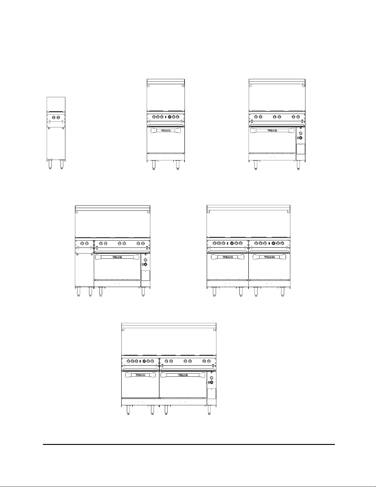
ELECTRIC RESTAURANT RANGE MODELS
EV12 EV24S EV36S
EV48S EV48SS
EV60SS
3 F-38251 (09-13) REV F
Page 4

ACCESSORY CODE
DESCRIPTION
RSHELF-ELEC
(24,36,48,60,72)
Reinforced High Shelf - 23" (584 mm) high stainless steel
backsplash with broiler mounting brackets for
Salamander/Cheesemelter.
STUB10-XL
(12,24,36,48,60,72)
10" Stainless steel stub riser. Available for 12", 24", 36", 48", 60",
and 72" ranges.
CONRACK-XL(20,26)
OVNRACK-XL(20,26)
RKGUIDE-XL
1 extra oven rack with convection ovens.
1 extra oven rack with standard ovens.
1 pair of rack guides (set of 2).
CASTERS-RR4
CASTERS-RR8
CASTERS-ADJRR4
Set of four (4) standard casters.
Set of eight (8) standard casters.
Set of four (4) adjustable casters. Two (2) sets required for 48",
60", and 72" ranges.
RCTWLBR-(24,36,48,60,72)
Towel Bar Assembly - Replaces standard bullnose. Available for
24", 36", 48", 60", and 72" ranges.
RCCUTBD-(24,36,48,60,72)
Cutting Board Assembly - Replaces standard bullnose. Available
for 24", 36", 48", 60", and 72" ranges. (Includes Sani-TUFF®
all-rubber cutting board)
INSTALLATION, OPERATION AND CARE OF
ELECTRIC RESTAURANT RANGES
KEEP THESE INSTRUCTIONS FOR FUTURE USE
GENERAL
Thoroughly read this entire manual and carefully follow all of the instructions provided.
Your Vulcan-Hart range is produced with quality workmanship and material. Proper installation, usage and
maintenance of your range will result in many years of satisfactory performance.
OPTIONAL FIELD INSTALLABLE ACCESSORIES
4 F-38251 (09-13) REV F
Page 5

RCCONRL-(24,36,48,60,72)
Condiment Rail Assembly - Replaces standard bullnose.
Available for 24", 36", 48", 60", and 72" ranges. (Does not
include condiment pans)
SHIELD-FRYRH
SHIELD-FRYLH
Fryer Splash Shield - Right hand or left hand side. Protects
range top against grease splatter from adjacent fryer.
VFLANGED-FEET/4
Set of four (4) flanged feet. Two (2) sets required for 48", 60",
and 72" ranges.
CURBMNT-XL4
Curb mounting kit. Two (2) sets required for 48", 60", and 72"
ranges.
INSTALLATION
UNPACKING
This range was inspected before leaving the factory. The transportation company assumes full
responsibility for safe delivery upon acceptance of the shipment. Immediately after unpacking, check for
possible shipping damage. If the range is found to be damaged, save the packaging material and contact
the carrier immediately.
Remove all shipping bands, blocking, and packaging. Remove the high shelf, and backsplash assembly.
Before installing, verify that the electrical service agrees with the specifications on the rating plate located
behind the kick panel on the left side. If the supply and equipment requirements do not agree, contact your
dealer or Vulcan-Hart immediately.
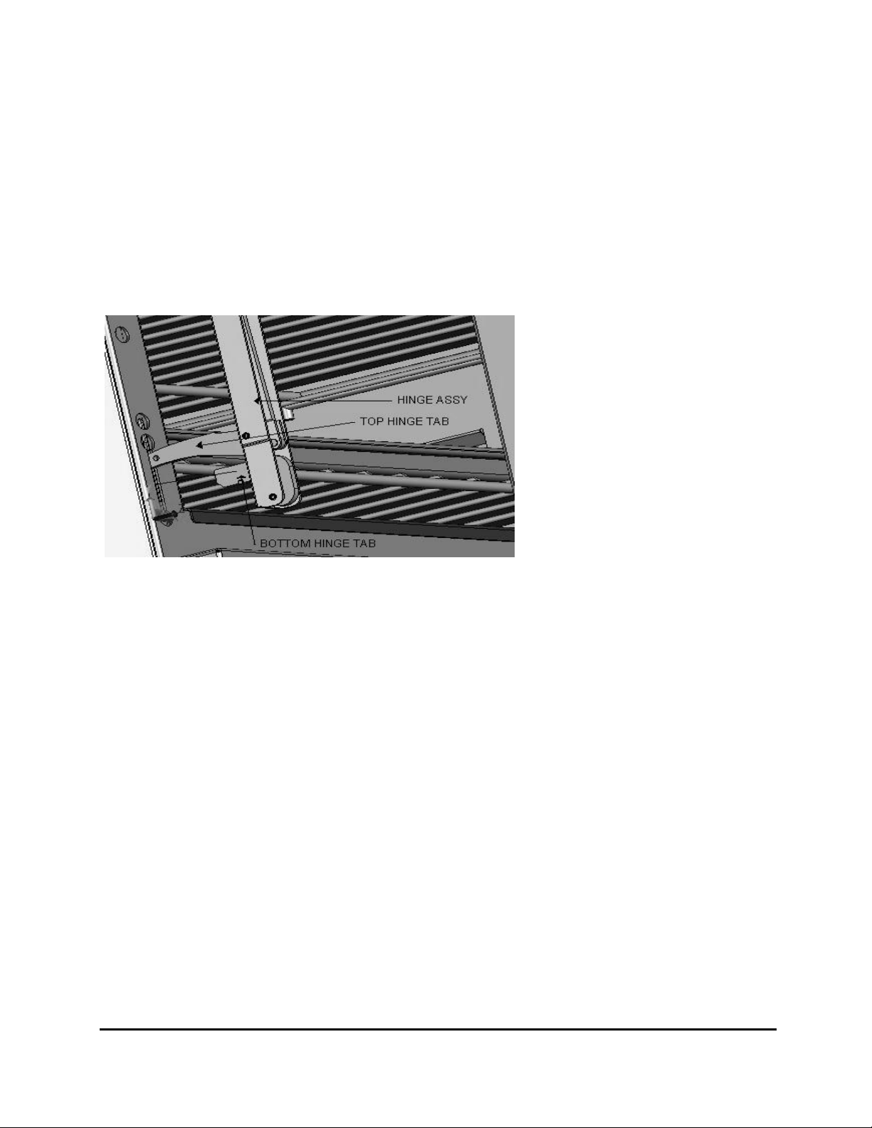
If it is required to remove the door and install it for access through a kitchen door, follow the instructions
below.
Door removal
1. Open door.
2. Grasp door firmly at both sides.
3. Lift door upward and pull it out so bottom hinge tab disengages.
* This may be easier to accomplish one side at a time.
4. Close door almost shut and lower slightly to disengage top hinge tab.
5. Pull door outward.
5 F-38251 (09-13) REV F
Page 6
Door installation
1. Grasp door firmly at both sides.
2. Starting with either LH or RH side top hinge tab, angle door and slide top hinge tab into opening
between hinge stop roller and hinge stop pin.
3. Lift door up (compress door hinge as if opening the door) and position bottom tab downward about 30
degrees down from horizontal.
4. Push door inward, inserting downward angled bottom hinge tab into opening just above hinge stop pin.
* Bottom hinge tab must enter chassis at downward angle to engage.
5. Bottom hinge tab should engage on hinge stop pin.
6. Open door and pull door outward until bottom hinge tab locks on hinge stop pin.
7. Repeat above steps for opposite side.
8. Open and close door to make sure door hinges are locked in place and door operates smoothly.
LOCATION
The installation location must allow adequate clearance for servicing and proper operation. A minimum front
clearance of 40" (1016 mm) is required. 0" sides and rear clearance from combustible and non-combustible
construction is required except when hot top sections are incorporated. Ranges incorporating hot top
sections require a 0" sides and rear clearance from non-combustible construction and 6" from combustible
construction.
INSTALLATION CODES AND STANDARDS
Your Vulcan range must be installed in accordance with state and local codes, or in the absence of local
codes, with National Electrical Code ANSI/NFPA-70 (latest edition) available from The National Fire
Protection Association, Batterymarch Park, Quincy, MA 02269. In Canada refer to Canadian electrical code
C22.1 Part 1 (latest edition).
ASSEMBLY
Leg/Caster Assembly
The range is shipped fully assembled, except for the legs. The range is provided with 6"(152 mm)
adjustable stainless steel legs (hardware included), packaged in a box located inside of the oven. A set of
6"(152 mm) casters or 6” adjustable casters are available as an optional field installable accessories.
6 F-38251 (09-13) REV F
Page 7
RANGE SERIES
LEGS TO INSTALL
CASTERS TO INSTALL
EV12 4 4
EV24 4 4
EV36 4 4
EV48 8 8
EV60 8 8
EV72 8 8
Restraining Connection Bracket
Installation of Legs/Casters:
1. Carefully tip or lift range to access bottom for leg installation.
2. Align holes in leg/caster mounting plate with pre-drilled holes in bottom of range located in each of
the four corners.
3. Attach mounting plate to bottom of range using four ¼ - 20 x ⅝“ self tapping screws (provided). If
casters are being installed, the locking casters should be mounted on the front.
4. After all legs/casters have been installed, carefully return the range to its upright position.
(For additional leg information, see Leveling section of this manual).
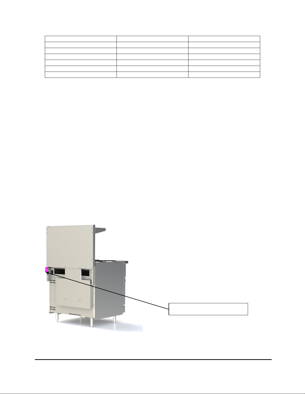
A permanently connected appliance mounted on casters and intended to be secured to the building
structure should adhere to the following:
a. Adequate means must be provided to limit the movement of the appliance without depending on or
transmitting stress to the electrical conduit;
b. The location(s) where restraining means are to be attached to the appliance needs to be on the
outside rear parts of the oven chassis frame of the Range (where the bottom rear heat shield is
bolted to the Range). Use brackets provided as connection points as shown below.
c. The appliance shall be installed using a flexible conduit.
If the range is installed on casters and is moved for any reason, it is recommended that the range be
re-leveled front to back and side to side for even baking.
7 F-38251 (09-13) REV F
Page 8

ELECTRICAL CONNECTIONS
ELECTRICAL AND GROUNDING CONNECTIONS MUST COMPLY WITH THE
APPLICABLE PORTIONS OF THE NATIONAL ELECTRICAL CODE AND/OR OTHER LOCAL
ELECTRICAL CODES.
DISCONNECT ELECTRICAL POWER SUPPLY AND PLACE A TAG AT THE
DISCONNECT SWITCH TO INDICATE THAT YOU ARE WORKING ON THE CIRCUIT.
Position the range in its final location. Bring conduit containing the proper supply wire to the range through
the knockout located on the bottom of the range. Select the size and type of field wire in accordance with the
National Electrical Code suitable for carrying the equipment's rated amps and voltage. Use field wires
suitable for 75°C on units carrying more than 80 amps.
If you have purchased an EV48, EV60 OR EV72 model, it will have two (2) electrical
connections. The left and the right portions of the range are supplied with individual branch
circuits, the connection points are found under each oven or in the right hand side control panel.
THE 48, 60 AND 72 INCH UNITS HAVE MORE THAN ONE SOURCE OF ELECTRICAL
SUPPLY. EACH SOURCE MUST BE CONNECTED IN ACCORDANCE WITH THE NATIONAL
ELECTRIC CODE (LATEST EDITION) OR OTHER LOCAL CODES.
Connect supply leads to field terminal block and green grounding lead to the labeled ground lug. The supply
wire should be anchored through the access hole with a bulkhead fitting.
Ranges ship wired for 3-phase service but may be changed to 1-phase, in the field. Refer to the wiring
diagram and schematic decal attached to the range for necessary alterations.
LEVELING
Place a carpenter's level on top of the range and level the range front-to-back and side-to-side by turning
the adjustable feet.
ACCESSORY BULLNOSE INSTALLATION
1.) Remove screws holding the switch cover in place and allow it to pivot down out of the way.
2.) Remove screws, from the front, holding the Bullnose in place.
3.) Slide standard Bullnose up to remove it from the range.
4.) Slide accessory back into the gap the standard Bullnose was removed from and align with
the side of range for fit.
5.) Start screw at one end of the Range, do not tighten completely.
6.) Going across the width of the Range install the next screw, as shown in Figure 2, set the
alignment and tighten screw completely.
7.) Install the remaining screws and tighten all screws completely.
8 F-38251 (09-13) REV F
Page 9
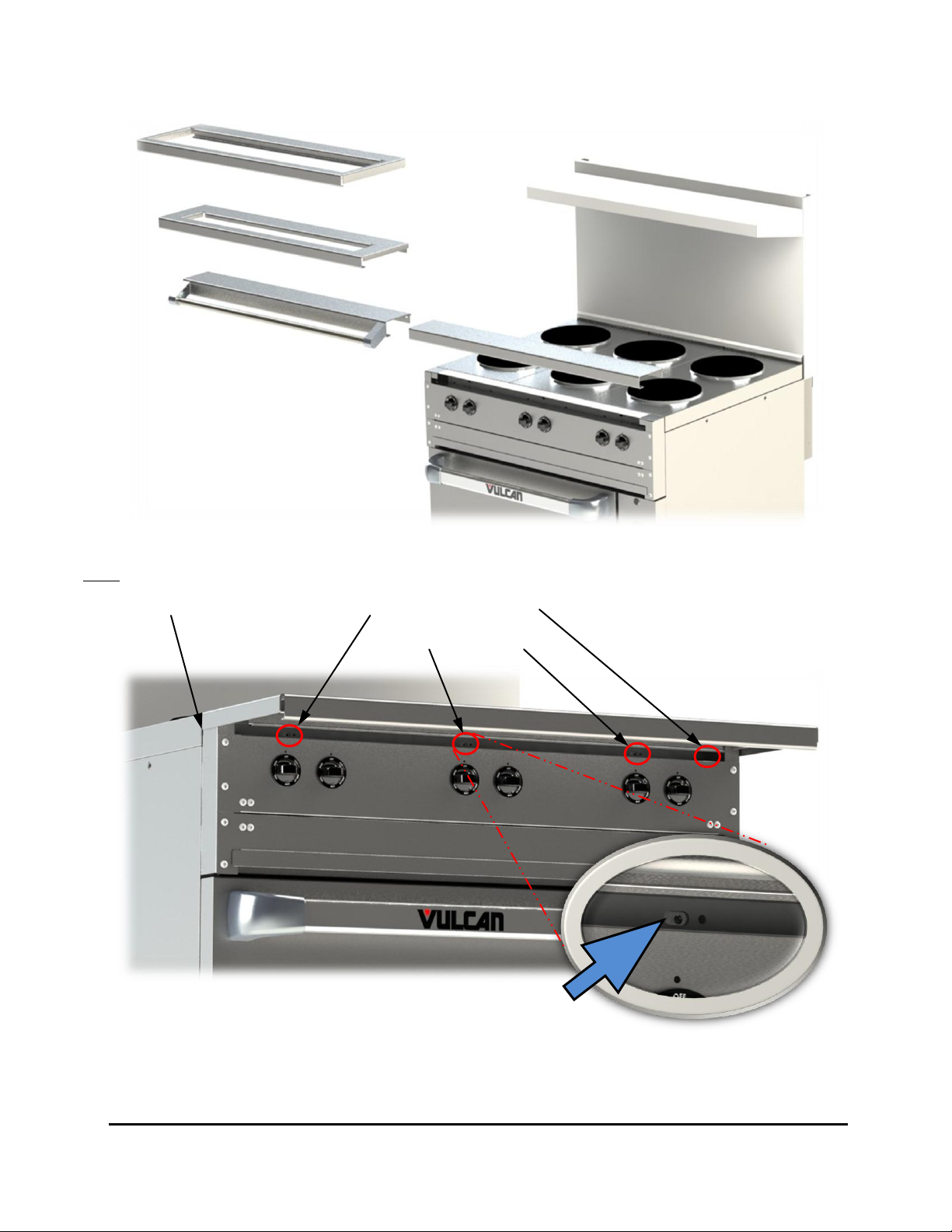
Condiment Rail
(Accessory)
Cutting Board
(Accessory)
Towel Bar
(Accessory)
Standard
Bullnose
Install Screws, #10-24 x
½ Phillips Head, in slots
on Bullnose as noted.
Note: Align the end of
the Bullnose with the
Range for fit.
Figure 1
Figure 2
9 F-38251 (09-13) REV F
Page 10
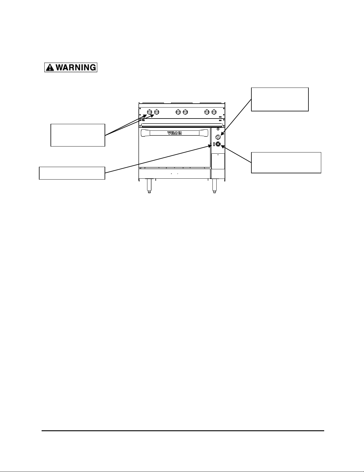
OPERATION
Element Control
Knobs
Oven Infinite
Switch Knob
Oven Indicator Light
Oven Thermostat
Knob
THE RANGE AND ITS PARTS ARE HOT. BE VERY CAREFUL WHEN
OPERATING, CLEANING OR SERVICING THE RANGE.
CONTROLS (Fig. 6)
Model EV36 Shown
Fig. 6
Element Controls — Infinite load switches that control and maintain heat to the surface plates. The
controls are arranged in pairs; the left knob controls the front plate and the right
knob controls the rear plate. NOTE: On 480 volt units, French plates are
controlled with a 3-heat switch (HIGH = 2000 watts, MED = 1000 watts, LOW =
500 watts).
Hot Top Switch — (Not shown.) A thermostat (1-10) controls and maintains heat to the top section.
Select desired heat level, (1 is minimum, 10 is maximum).
Griddle Thermostat — (Not shown.) Regulates the amount of heat needed to maintain the set
temperature. Each 12" (305 mm) section of the griddle has its own thermostat
with a temperature range of 200°F (93°C) to 550°F (288°C).
Griddle Indicator Light — (Not shown.) Will be lit until the selected temperature is reached or when it is
being maintained.
Oven Thermostat — Regulates the amount of heat needed to control and maintain oven temperature
around the desired set temperature. The temperature range is from 200°F
(93°C) to 550°F (288°C). Turn dial counterclockwise to increase temperature
and clockwise to decrease temperature.
Infinite Switch for Oven — Provides control for top browning element. Adjust as needed for the amount
Top Heating Element of top heat required in order to brown product as desired. NOTE: Infinite switch
not available on 480 volt units. This position on the panel will be filled with a
panel plug.
Oven Indicator Light — Will be lit until the selected temperature is reached or when it is being
maintained.
10 F-38251 (09-13) REV F
Page 11
BEFORE FIRST USE
Cleaning
Clean the range and all accessories with water and a mild detergent. Rinse thoroughly and wipe dry with a
soft clean cloth.
Griddle Seasoning
A new griddle surface must be seasoned. The metal surface of the griddle is porous. Food tends to get
trapped in these pores and stick; therefore, it is important to "season" or "fill up" these pores with cooking oil
before cooking. Seasoning gives the surface a slick, hard finish from which the food will release easily.
To season, heat griddle top section at a low setting. Pour one ounce of cooking oil per square foot of surface
over the griddle top section. With an insulated cloth, spread the oil over the entire griddle surface to create
a thin film. Wipe off any excess oil with an insulated cloth.
Repeat this procedure 2 to 3 times until the griddle has a slick surface.
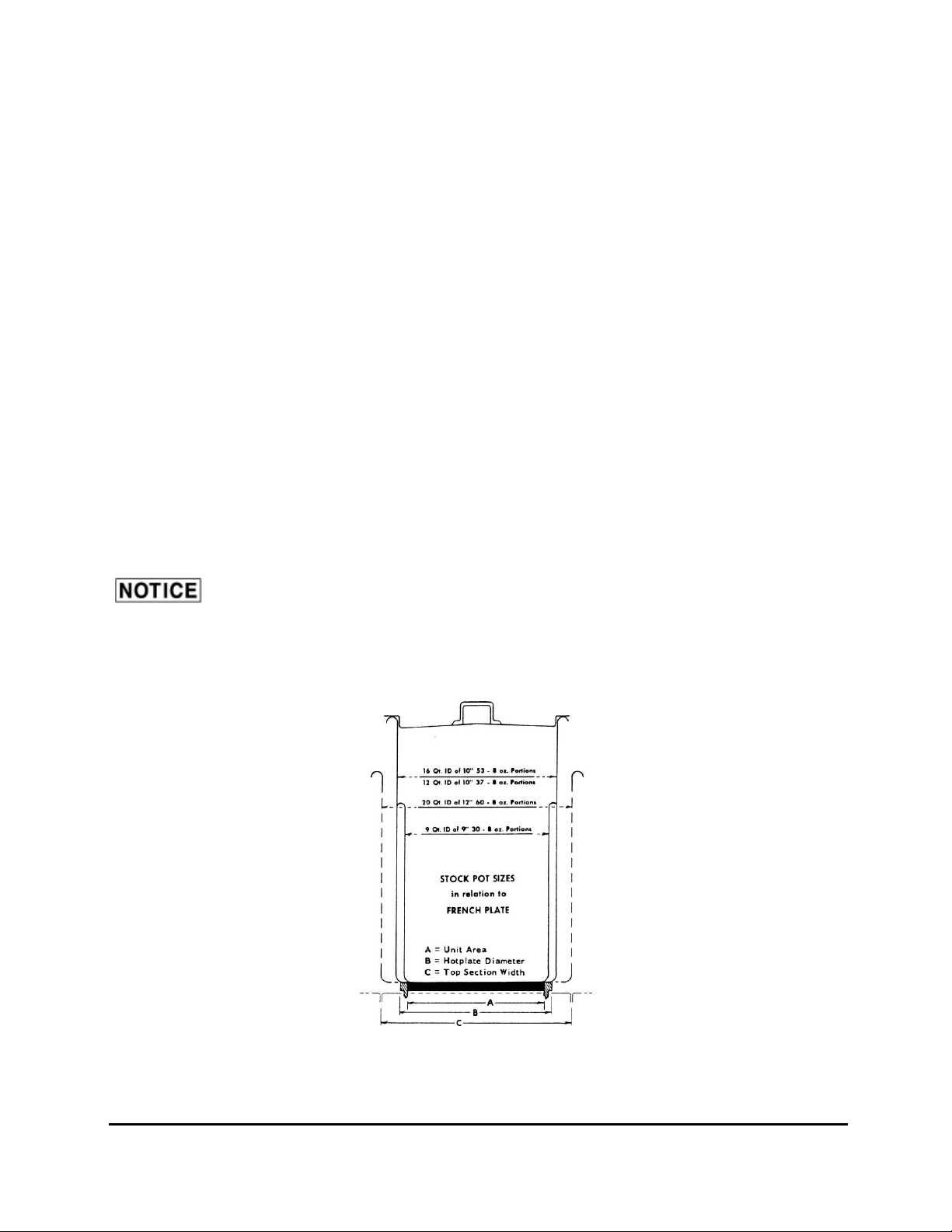
FRENCH PLATES
French plates are most efficient when used with utensils having a maximum inside diameter of 10" (254)
or a minimum inside diameter of 9" (229). Stock pots of 9, 12 and 16 qt. capacities are recommended for
bulk cooking. (Fig. 7)
It is important that the utensil used has a flat bottom that sits uniformly on the surface of the
plate. Utensils with curved bottoms (either through design or warped from use) will have poor contact and
therefore poor heat transfer. This will result in poor cooking performance.
Fig. 7
11 F-38251 (09-13) REV F
Page 12

The French (solid surface) Plates are rated for 2000 Watts and are controlled by an infinite heat switch. A
French (solid surface) Plate will reach cooking temperature from room temperature in 5 to 7 minutes at a HI
switch setting.
Each control knob is marked HI, MED, LO, MED-LO, and VERY-LO. The HI setting is full heat. Use the HI
setting to start cooking quickly and to bring water to a boil.
Some DO'S and DO NOT'S of Surface Cooking
DO use utensils to fit the tops (9" to 10" [229 to 254 mm] inside diameter).
DO use flat-bottomed, straight-sided pots and pans.
DO use covers for stock pot work. Water will boil much sooner and much less heat is required for cooking in
a covered container. Less water may be used, thereby retaining vitamins and minerals in the food.
DO turn off plates a few minutes before cooking is completed to use the heat stored in the plate.
DO NOT allow surface plates to idle unloaded at HI switch settings. The surface plates will reach
very high temperatures, and this can cause the casting to warp or dome. Plates idled at a setting of
MED-LO and turned to HI when loaded, will perform bulk cooking jobs just as rapidly, without
damage to the plates. Damage caused by plates left running unloaded on HI will void the warranty.
HOT TOPS
Hot Tops can make up for the irregularity of stock pots that have an inside diameter of over 10”. Pots can
overlap from one Hot Top section to another without any loss of heating area.
It is important that the utensil used has a flat bottom that sits uniformly on the surface of the
hot top plate. Utensils with curved bottoms (either through design or warped from use) will have poor
contact and therefore poor heat transfer. This will result in poor cooking performance.
The Hot Top section is rated for 2500 Watts and are controlled by snap action thermostatic controller, with
knob indicator marks from 0 to 10 (with 10 being the highest temperature setting). A Hot Top section will
reach cooking temperature from room temperature in 15 to 20 minutes at a 10 thermostat setting.
Some DO’S of Hot Top Cooking
DO use flat-bottomed, straight-sided pots and pans.
DO use covers for stock pot work. Water will boil much sooner and much less heat is required for cooking in
a covered container. Less water may be used, thereby retaining vitamins and minerals in the food.
GRIDDLE
See BEFORE FIRST USE in this manual for griddle seasoning procedure.
12 F-38251 (09-13) REV F
Page 13

This griddle plate is steel, but the surface is relatively soft and can be scored or
dented by the careless use of a spatula or scraper. Be careful not to dent, scratch, or gouge the
plate surface. Do not try to knock off loose food that may be on the spatula by tapping the corner
edge of the spatula on the griddle surface.
Griddles are supplied with one 3400 watt heating element per 12” of griddle surface. Each heating element
is individually controlled by a thermostat with a range of 200°F to 550°F (93°C to 288°C).
OVEN
Never cover the oven deck or rack with aluminum foil. The oven will not operate
properly and the range may be damaged.
Model EV24S, EV36S and EV48S ranges have a single oven; Model EV48SS, EV60SS AND EV72SS
ranges have two separate ovens. Each oven is equipped with top and bottom heating elements. The top
element has an infinite heat switch for browning. THIS IS NOT A BROILER ELEMENT. (infinite switch is
not available on the 480 volt range for the top element)
The oven has an input of 5000 W., 3750 W. for the bottom element and 1250 W. for the top element.
Preheating
Thoroughly preheat the oven by setting the switch and the thermostat to the desired temperature. When the
red light goes out, the oven is ready for use. For full loads and delicate baked products, it may be desirable
to allow the oven to cycle (red light on and off) a second time before loading.
Baking
Most products can be baked with the top element infinite switch set between VERY LO and LO.
Hard-to-brown products, such as corn bread or biscuits, may require a top switch setting of MED to HI. Start
off by using a LO setting on top element and then increase only as needed.
Roasting
Place meat on a rack in an open pan with sides sufficiently high to retain the drippings. Roasting may be
done on the oven rack or the deck. For best results, roast at the low temperatures of 200°F (93°C) to 325°F
(163°C) recommended by the Department of Agriculture and the American Meat Institute. Most meats may
be roasted with the infinite heat switch set at HI. If heavy browning on poultry is not desired, the switch
should be set between MED-LO and VERY-LO.
The top oven element is not suitable for broiling, and will not operate independent of the oven thermostat
(bottom element).
POWER OUTAGE
If a power outage occurs, the range will automatically shut down. When power is restored, the range will
automatically resume normal functions. If the range is left unattended during the power outage, turn all
control knobs/switches OFF. When power is restored, turn desired control knobs/switches back ON. The
unit will be preheated in 5 minutes and normal cooking operations can be resumed.
13 F-38251 (09-13) REV F
Page 14

CLEANING
DISCONNECT ELECTRICAL POWER SUPPLY BEFORE CLEANING.
DO NOT use Dawn ® dish detergent to clean the exterior or interior components of the range.
DO NOT use scouring powder. It is extremely difficult to remove completely. It can build up accumulations
that will damage the range.
DO NOT use cleaning products containing TSC.
Clean all parts of the range and the oven with a soft cloth and warm water and detergent. Rinse thoroughly
and wipe dry with a soft clean cloth.
Griddle
Scrape the griddle with an approved scraper after each use. The griddle grease can should be emptied on
a routine basis. A weep hole is provided to indicate that the grease can is near full capacity. Failure to empty
the grease can will cause it to overflow and may result in damage to the range. Weekly, or more often if
necessary, thoroughly clean the griddle surface. You may use a griddle screen or stone with a little grease,
rubbing with the grain of the metal while it is still warm, or use water and detergent with a steel brush. The
detergent must be thoroughly removed. After each thorough cleaning, the griddle must be re-seasoned
(see BEFORE FIRST USE in this manual).
Avoid build-up of caked grease under the drip edge and around the outside edges of the griddle.
If the griddle is to be shut down for an extended period, put a heavy coat of grease over the griddle plate.
Oven
Clean oven and oven door daily, especially if fruit pies or tomato sauces were baked, meats roasted, and if
there have been spillovers. Failure to clean spills may result in corrosion of metal components.
If the oven liners and decks are heavily soiled, ammonia or oven cleaner may be used to remove spillage of
burned on sugar and grease, but must be thoroughly rinsed with water to prevent corrosion.
After processing some foods at low temperatures, odors may linger in the oven. These odors may be
cleared by setting the thermostat at 500°F (260°C) and allowing the oven to operate unloaded for 30 to 45
minutes.
14 F-38251 (09-13) REV F
Page 15

MAINTENANCE
THE RANGE AND ITS PARTS ARE HOT. BE VERY CAREFUL WHEN
OPERATING, CLEANING OR SERVICING THE RANGE.
Disconnect power supply and follow lockout / tagout
procedures before cleaning and servicing the appliance.
SERVICE AND PARTS INFORMATION
To obtain service and parts information concerning this range, contact the Vulcan-Hart Service Department
in your area or Service Department at the address or phone number shown on the front cover of this
manual.
15 F-38251 (09-13) REV F
Page 16

ELECTRICAL CONNECTION INFORMATION
Model
Configuration
X-Y Y-Z Z-X
Single
Phase
X Y Z
Single
Phase
X Y Z
Single
Phase
X Y Z
Single
Phase
EV12-2FP 2.0 2.0 0.0 4.0 8.0 17.0 8.0 19.0 7.0 14.0 7.0 17.0 3.6 7.2 3.6 8.3
EV12-1HT 5.0 24.0 21.0 10.4
EV24S-4FP 5.0 4.0 4.0 13.0 37.5 37.5 33.3 62.5 32.5 32.5 28.9 54.2 16.3 16.3 14.4 27.1
EV24S-2HT 5.0 5.0 5.0 15.0 41.6 41. 6 41.6 72.1 36.1 36.1 36.1 62.5 18.1 18.1 18.1 31.2
EV36S-6FP 4.0 8.0 5.0 17.0 37.5 50.0 54.1 81.7 32.5 43.3 46.9 70.8 16.3 21.7 23.5 35.4
EV36S-3HT 5.0 10.0 5.0 20.0 41.6 62.5 62.5 96.2 36.1 54.1 54.1 83.3 18.1 27. 1 27.1 41.7
EV36S-2HT2FP 4.0 10.0 5.0 19.0 37.5 58.3 62.5 91.4 32.5 50.5 54.1 79.2 16.3 25.3 27.1 39.6
EV36S-1HT4FP 4.0 9.0 5.0 18.0 37.5 54.1 58.3 86.5 32.5 46.9 50.5 75.0 16.3 23.5 25.3 37. 5
EV36S-2FP24G 3.4 7.4 5.0 15.8 35.0 45. 0 51.6 76.0 30.3 39.0 44.7 65.8 15.2 19.5 22.4 32.9
EV36S-1HT24G 3.4 8.4 5.0 16.8 35.0 49.1 55.8 80. 8 30.3 42.6 48.4 70.0 15.2 21.3 24.2 35.0
EV36S-4FP12G 3.4 8.0 5.0 16.4 35.0 47. 5 54.1 78.8 30.3 41.1 46.9 68.3 15.2 20.6 23.3 34.2
EV36S-2HT12G 3.4 10.0 5.0 18.4 35.0 55.8 62.5 88.5 30.3 48.4 54.1 76.7 15.2 24.2 27.1 38.4
EV36S-36G 3.4 6.8 3.4 15.2 35. 0 42.5 49.1 73.1 30.3 36.8 42.6 63.3 15.2 18.4 21.3 31.7
Key - FP = French Plates (2 per 12inch section) HT = Hot Top (1 per 12 inch section) G = Griddle (can actually have a 12, 24 or 36 inch Griddle)
All Griddle s less than 36 inches are always positioned on the right hand side of the range.
Kilowatts
208 Volt Amps
240 Volt Amps
480 Volt Amps
24 Inch Range w/Standard Oven
36 Inch Range w/Standard Oven
12 Inch Range
All ranges over 36 inches in width have two electrical connections. Ensure both
power supplies have been disconnected before beginning service on the appliance.
DOUBLE RANGES
Ranges ordered over 36 inches wide are constructed as follows:
EV48S - Consists of an EV36S and an EV12
EV48SS - Consists of two EV24S
EV60SS - Consists of an EV24S and an EV36S
EV72SS - Consists of two EV36S
16 F-38251 (09-13) REV F
Page 17

0 7S0 1234567089:273;0<=>010
0 0
Page 18

0 740 1234567089:273;0<=>010
0 0
Page 19

0 7:0 1234567089:273;0<=>010
0 0
Page 20

0 590 1234567089:273;0<=>010
Page 21

0 570 1234567089:273;0<=>010
0 0
Page 22

NOTES
22 F-38251 (09-13) REV F
Page 23

0 550 1234567089:273;0<=>010
NOTES
Page 24

0 570 1234567089:273;0<=>010
0 0
Page 25

0 590 1234567089:273;0<=>010
Page 26

0 7:0 1234567089:273;0<=>010
0 0
Page 27

0 740 1234567089:273;0<=>010
0 0
Page 28

0 7S0 1234567089:273;0<=>010
0 0
Page 29

0 7@0 1234567089:273;0<=>010
SPÉCIFICATIONS ÉLECTRIQUES
0
Clé – FP = Feux de type français (2 par section de 12 po) HT = Surface coup de feu (1 par section de 12 po) G = Gril lisse (on peut commander
des grils de 12, 24 ou 36 po)
Tous les grils lisses de moins de 36 pouces sont toujours montés du côté droit de la cuisinière.
Toutes les cuisinières d’une largeur de plus de 36 pouces comportent deux
connexions électriques. Assurez-vous que les deux sources d’alimentation ont été débranchées avant de
commencer tout entretien de l’appareil.
CUISINIÈRES DOUBLES
Les cuisinières d’une largeur de plus de 36 pouces sont construites de la façon suivante :
• EV48S – Jumelage d’un EV36S avec un EV12
• EV48SS – Jumelage de deux EV24S
• EV60SS – Jumelage d’un RV24S et d’un EV36S
• EV72SS – Jumelage de deux EV36S
0 0
Page 30

0 760 1234567089:273;0<=>010
ENTRETIEN
LA CUISINIÈRE ET SES COMPOSANTS SONT CHAUDS.
EXERCEZ UNE EXTRÊME PRUDENCE LORS DE SON UTILISATION, NETTOYAGE
ET ENTRETIEN.
Avant de nettoyer et d’entretenir cet appareil, coupez
l’alimentation électrique et observez les procédures de verrouillage et
d’étiquetage appliance.
RENSEIGNEMENTS SUR L’ENTRETIEN ET LES PIÈCES DE RECHANGE
Pour obtenir des renseignements sur l’entretien de l’appareil ou sur les pièces de rechange, communiquez avec
le service de l’entretien Vulcan-Hart près de chez-vous ou à l’adresse ou numéro de téléphone inscrits sur la page
couverture de ce manuel.
Page 31

0 7?0 1234567089:273;0<=>010
NETTOYAGE
DÉBRANCHEZ L’APPAREIL AVANT DE LE NETTOYER
N’UTILISEZ PAS le détergent à vaisselle Dawn® pour nettoyer les composants
extérieurs et intérieurs de la cuisinière®.
N’UTILISEZ PAS de poudre à récurer. Elle s’enlève très difficilement et peut s’accumuler, ce qui risque
d’endommager l’appareil.
N’UTILISEZ PAS des produits contenant des TSC.
Nettoyez la cuisinière et le four avec de l’eau chaude savonneuse et un chiffon doux. Rincez à fond et essuyez à
l’aide d’un chiffon doux et propre.
Gril lisse
Nettoyez le gril lisse avec une spatule approuvée après chaque usage. Le tiroir capteur de graisse devrait être
vidé sur une base routinière. Un trou de purge indique que le tiroir de graisse est près de sa pleine capacité. Si le
tiroir de graisse n’est pas vidé, il débordera et cela pourrait endommager la cuisinière. Hebdomadairement, ou
plus souvent au besoin, nettoyez à fond la surface du gril lisse au moyen d’une pierre pour plaque lisse et d’un
peu de graisse. Frottez dans le sens du grain pendant qu’elle est encore chaude. On peut aussi la nettoyer à l’eau
et au détergent à l’aide d’une brosse d’acier. Toute trace de détergent doit être soigneusement retirée. Après
chaque grand nettoyage, le gril lisse doit être conditionné de nouveau (voir la section AVANT LA PREMIÈRE
UTILISATION de ce mode d’emploi).
Évitez l’accumulation de graisse collée sous le rebord du trou d’égouttement et autour des bords extérieurs du
gril lisse.
Si le gril lisse ne sera pas utilisé avant une longue période, étendez une épaisse couche de graisse sur toute sa
surface.
Le four
Nettoyez le four et la porte quotidiennement, spécialement après la cuisson de tartes aux fruits, de sauces aux
tomates et de viandes ou après des débordements. Si on ne le fait pas, il peut en résulter de la corrosion dans les
composants de métal.
Si les parois et les soles du four sont très sales, enlevez les débordements de sucre ou de graisse brûlés au moyen
d’ammoniaque ou d’un nettoyant pour four, mais ceux-ci doivent être rincés à l’eau en profondeur pour éviter la
corrosion.
L’odeur de certains aliments cuits à basse température peut persister dans le four. Pour éliminer ces odeurs,
faites chauffer le four à vide à 260 °C (500 °F) pendant 30 à 45 minutes.
Page 32

0 730 1234567089:273;0<=>010
Cette plaque lisse est en acier, mais sa surface est relativement tendre et peut rayer ou
bosseler suite à l’utilisation d’une spatule ou d’un grattoir d’une manière négligente. Prenez soin de ne
pas la bosseler, l’égratigner ou la rayer. Ne pas y cogner les coins ou les rebords d’une spatule pour tenter
de déloger les particules d’aliments qui pourraient s’y trouver.
Les grils lisses sont équipés d’un élément chauffant de 3 400 watts par zone de gril de 305 mm (12 po). Chaque
élément est commandé par un thermostat séparé gradué de 93 à 288 °C (200 à 550 °F)
FOUR
Ne jamais recouvrir la sole ou la grille de papier d’aluminium. Le four ne fonctionnera
pas correctement et la cuisinière pourrait être endommagée.
Les cuisinières EV24S et EV36S sont pourvues d’un seul four tandis que les modèles EV48S, EV60SS et EV72SS sont
pourvus de deux fours séparés. Chaque four est muni d’éléments chauffants supérieurs et inférieurs. L’élément
supérieur est commandé par un commutateur à réglage continu pour le brunissage. CECI N’EST PAS UN ÉLÉMENT
À GRILLER. (L’interrupteur à réglage continu n’est pas livrable pour un élément supérieur de 480 volts).
La puissance totale du four est de 5 000 W, soit 1 250 W pour l’élément chauffant supérieur et 3 750 W pour
l’élément chauffant inférieur.
Préchauffage
Préchauffez le four avant de l’utiliser. Pour ce faire, réglez le commutateur et le thermostat à la température
désirée. Lorsque le voyant rouge s’éteint, le four est prêt pour la cuisson. Pour les charges pleines et les produits
de boulangerie et pâtisseries délicats, il est préférable de laisser le voyant rouge s’allumer et s’éteindre une
seconde fois avant de procéder au chargement du four.
Cuisson pâtisserie/boulangerie
On peut cuire la plupart des produits en réglant le commutateur de l’élément chauffant supérieur entre
VERY LO (TRÈS BAS) et LO (BAS). Il se peut que les aliments qui brunissent difficilement, comme le pain de maïs
ou les biscuits, requièrent un réglage MED (MOYEN) ou HI (ÉLEVÉ). Commencez par utiliser le réglage LO (BAS)
sur l’élément chauffant supérieur puis augmentez seulement si nécessaire
Rôtissage
Mettez la viande dans un plat à rôtir dont les bords sont suffisamment hauts pour empêcher le jus de cuisson de
déborder. Déposez le plat sur la grille ou sur la sole. Pour de meilleurs résultats, le ministère de l’agriculture des
États-Unis et l’Institut américain de la viande recommandent de faire rôtir la viande à basse température, soit
entre 93 et 163 °C (200 et 325 °F). Réglez le commutateur à réglage continu à HI (ÉLEVÉ) pour la plupart des
viandes. Dans le cas de la volaille, réglez-le entre MED-LO (MOYENNEMENT BAS) et VERY-LO (TRÈS BAS) pour
empêcher de trop brunir.
L’élément chauffant supérieur du four n’est pas approprié pour le grillage et ne fonctionne pas séparément du
thermostat du four (élément inférieur).
PANNE DE COURANT
En cas de panne de courant, la cuisinière s’éteint automatiquement. Dès que le courant est rétabli, elle poursuit son
cycle de cuisson normal. Si elle était sans surveillance pendant une panne de courant, mettez tous les
interrupteurs et boutons de commande à OFF (Arrêt). Dès que le courant est rétabli, remettez ceux-ci à
ON (Marche). L’appareil préchauffe pendant cinq minutes avant de poursuivre la cuisson normalement.
!
Page 33

0 750 1234567089:273;0<=>010
Les feux à la française (à surface pleine) fonctionnent à une puissance nominale de 2 000 W et sont commandés
par un commutateur à réglage continu. Ils requièrent de 5 à 7 minutes pour atteindre la température de cuisson
au réglage ÉLEVÉ à partir de la température ambiante.
Chaque bouton de commande porte les inscriptions HI, MED, LO, MED-LO et VERY-LO (ÉLEVÉ, MOYEN, BAS,
MOYENNEMENT BAS et TRÈS BAS respectivement). La marque ÉLEVÉ correspond au réglage le plus puissant.
Utilisez ce réglage pour amorcer la cuisson rapidement ou amener l’eau à ébullition.
Certaines choses À FAIRE et NE PAS FAIRE à l’égard de la cuisson sur la surface
À FAIRE : utilisez des marmites et casseroles de même dimension que les plaques (diamètre intérieur de 229 à
254 mm (9 à 10 po).
À FAIRE : utilisez des marmites et casseroles à fond plat et côtés droits.
À FAIRE : couvrez les marmites. L’eau vient ainsi à ébullition beaucoup plus rapidement. De plus, la cuisson dans
un récipient couvert requiert une quantité moindre d’eau et d’énergie, de sorte que les aliments conservent
leurs vitamines et minéraux
À FAIRE : éteignez les feux quelques minutes avant la fin de la cuisson de façon à utiliser la chaleur
emmagasinée dans la plaque.
NE PAS FAIRE : laisser les plaques chauffer à vide à intensité élevée, car elles atteindront des
températures très élevées qui risquent de provoquer le gauchissement ou le bombement de la fonte. Les
plaques chauffées à vide à l’intensité MED-LO (MOYEN-ÉLEVÉ) puis HI (ÉLEVÉ) lorsque des marmites ou
casseroles s’y trouvent assurent une cuisson tout aussi rapide sans toutefois endommager les plaques.
Les dommages causés aux plaques laissées à chauffer sans charge au réglage HI (ÉLEVÉ) annuleront la
garantie.
PLAQUE COUP DE FEU
Les plaques coup de feu peuvent compenser pour les marmites dont le diamètre interne dépasse 254 mm
(10 po). Les marmites peuvent dépasser d’une section coup de feu à une autre sans aucune perte de zone
de chauffage.
Il est important d’utiliser des marmites ou des casseroles à fond plat qui couvrent
uniformément toute la surface de la plaque coup de feu. Les marmites ou casseroles à fond courbé (que ce
soit par design ou qu’elles soient gauchies par l’utilisation) auront un mauvais contact et, par le fait même,
le transfert de chaleur ne se fera pas bien. Ceci aura pour résultat une piètre performance de cuisson.
Les sections coup de feu ont une intensité de 2 500 watts et sont commandées par un contrôle à action
rapide dont le bouton est marqué de 0 à 10 (10 étant le réglage de température le plus élevé). À partir de la
température ambiante, une section coup de feu atteindra la température de cuisson en 15 à 20 minutes à
un réglage de thermostat de 10.
Choses À FAIRE et NE PAS FAIRE à l’égard de la cuisson sur une plaque coup de feu
À FAIRE : utilisez des marmites et casseroles à fond plat et côtés droits.
À FAIRE : couvrez les marmites. L’eau vient ainsi à ébullition beaucoup plus rapidement. De plus, la cuisson dans
un récipient couvert requiert une quantité moindre d’eau et d’énergie, de sorte que les aliments conservent
leurs vitamines et minéraux.
GRIL LISSE
Se reporter à sa section AVANT LA PREMIÈRE UTILISATION pour le conditionnement du gril lisse.
Page 34

0 770 1234567089:273;0<=>010
AVANT LA PREMIÈRE UTILISATION
Nettoyage
Nettoyez la cuisinière et tous les accessoires avec de l’eau et du détergent doux. Bien rincer et essuyer à l’aide
d’un chiffon propre et doux.
Conditionnement du gril lisse
Il est nécessaire de conditionner un gril lisse neuf. Sa surface de métal est poreuse. Les aliments ont tendance à
s’incruster dans les pores et à y adhérer; Il est donc important de « conditionner » ou de « remplir » ces pores
d’huile de cuisson avant de commencer. Le conditionnement donne à la surface un fini lisse et dur, ce qui facilite
l’enlèvement des aliments.
Pour la conditionner, chauffez la surface du gril à basse température et versez-y une once d’huile de cuisson par
pied carré. À l’aide d’un chiffon isolé, étendez l’huile sur toute la surface du gril lisse de manière à obtenir un
mince film puis essuyez tout surplus d’huile avec le chiffon.
Répétez la manœuvre à deux ou trois reprises jusqu’à ce que la surface soit bien lisse.
FEUX À LA FRANÇAISE
Pour maximiser l’efficacité des plaques à la française, utilisez des marmites ou casseroles dont le diamètre
intérieur n’excède pas 254 mm (10 po) ou mesure au moins 229 (9 po). On recommande l’utilisation de marmites
de 8,4, 11,3 et 15,4 litres (9, 12 et 16 pintes) pour la cuisson en vrac (Fig. 7).
Il est recommandé d’utiliser des marmites ou des casseroles à fond plat qui couvrent toute la
surface de la plaque. Les marmites ou casseroles à fond courbé (que ce soit par design ou qu’elles soient
gauchies par l’utilisation) auront un mauvais contact et, par le fait même, le transfert de chaleur ne se fera pas
bien. Ceci aura pour résultat une piètre performance de cuisson.
Fig. 7
Page 35

0 790 1234567089:273;0<=>010
FONCTIONNEMENT
LA CUISINIÈRE ET SES COMPOSANTS SONT CHAUDS. EXERCEZ UNE EXTRÊME
PRUDENCE LORS DE SON UTILISATION, NETTOYAGE ET ENTRETIEN.
COMMANDES (Fig. 6)
Modèle EV36 illustré
Fig. 6
Commande des éléments Commutateurs à réglage continu servant à régler et à maintenir la température des
chauffants — feux de surface. Ces commutateurs fonctionnent par paires; le bouton de gauche
commande la température du feu avant et celui de droite, la température du feu arrière.
NOTA : Pour les appareils de 480 V, les feux à la française sont commandés par un
commutateur à 3 positions (FEU ÉLEVÉ = 2 000 W, FEU MOYEN = 1 000 W, FEU
BAS = 500 W).
Interrupteur de la surface (Non illustré). Un thermostat (1-10) servant à régler et à maintenir la température
coup de feu — de la section coup de feu. Choisir le niveau de chaleur désiré, 1 étant le minimum et
10 le maximum.
Thermostat de gril lisse — (Non illustré). Dispositif servant à régler la quantité de chaleur requise pour le
maintien de la température désirée. Chaque section de 12 po (305 mm) du gril lisse
est dotée de son propre thermostat dont la fourchette de température va de 93 à
288 °C (200 à 550 °F).
Voyant du gril lisse — (Non illustré) Ce voyant demeure allumé tant que la température désirée n’est pas
atteinte ou maintenue.
Bouton du thermostat Bouton servant à régler la quantité de chaleur requise pour le réglage et le maintien
du four — de la température du four. Celui-ci est gradué de 93 à 288°C (200 à 550 °F). Pour
augmenter la température, tournez le bouton dans le sens contraire de l’horloge et
dans le sens inverse pour la réduire.
Commutateur à réglage Dispositif servant à commander la cuisson par l’élément chauffant du haut pour
continu de l’élément brunir. Réglez au besoin selon la température désirée pour brunir le produit.
supérieur du four NOTA : Le commutateur à réglage continu n’est pas disponible pour les appareils de
480 V. L’endroit où il est placé sur le panneau sera bouché par une fiche.
Voyant de four — Lorsqu’il est allumé, ce voyant indique que la température désirée est atteinte ou
maintenue.
V/$./(B0E)0
&/--'(E)0E)B0
G%G-)(.B0&M'$FF'(.B0 0
Z/--$.'.)$D0O0DG H%' H)0
&/(.+($0E$0F/$D0
>/['(.0E)0B+H('%+B'.+/(0
E$0F/$D0
V/$./(0E$0.M)D-/B.'.0
E$0F/$D0
Page 36

0 :0 1234567089:273;0<=>010
!
0
0
0
0
!
U'P%)..)0O0&/(E+-)(.B0
8L&&)BB/+D);0
U'P%)..)0O0EG&/$,)D0
8L&&)BB/+D);0
V'DD)0O0B )D#+)..)B0
8L&&)BB/+D);0
U'P%)..)0'#'(.0
'DD/(E+)0B.'(E'DE0
V$%%(/B)0
W(B.'%%)X0%)B0#+B0&D$&+F/D-)B07925?0Q0Y0,/0
E'(B0%)B0F)(.)B0E)0%'0.'P%)..)0'DD/(E+)0
.)%0*$)0(/.G"0
Remarque!:0'%+H()X0P+)(0%)0
P/$.0E$0D)P/DE0'DD/(E+0'$0
P/$.0E)0%'0&$+B+(+CD)"0
1+H$D)070
1+H$D)050
0
Page 37

0 40 1234567089:273;0<=>010
RACCORDEMENTS ÉLECTRIQUES
LE RACCORDEMENT ÉLECTRIQUE ET LA MISE À LA TERRE DOIVENT ÊTRE
CONFORMES AUX NORMES CONCERNÉES DU CODE CANADIEN DE L’ÉLECTRICITÉ OU DE TOUT AUTRE
CODE D’ÉLECTRICITÉ EN VIGUEUR.
COUPEZ L’ALIMENTATION ÉLECTRIQUE DE L’APPAREIL ET APPOSEZ UNE
ÉTIQUETTE AU DISJONCTEUR POUR AVERTIR QU’UN TECHNICIEN TRAVAILLE SUR LE CIRCUIT.
Placez la cuisinière à l’emplacement prévu. Passez le conduit renfermant le fil d’alimentation approprié à la
cuisinière dans la débouchure située dans le bas de l’appareil. Il vous faut choisir le calibre et le type de fil
conformément au Code canadien de l’électricité et en fonction de la tension et l’intensité nominale de l’appareil.
Pour les appareils de plus de 80 A, utilisez des fils pouvant supporter des températures allant jusqu’à 75 °C (167 °F).
Si vous avez acheté un modèle EV48, EV60 ou EV72, il y aura deux (2) raccordements
électriques. Les parties à gauche et à droite de la cuisinière sont munies de circuits de dérivation individuels
et on trouve les points de raccordement sous chaque four ou dans le panneau de commande du côté
droit.
LES APPAREIL DE 48, 60 ET 72 PO COMPORTENT PLUS D’UNE SOURCE D’ALIMENTATION
ÉLECTRIQUE. CHAQUE SOURCE DOIT ÊTRE RACCORDÉE CONFORMÉMENT AU CODE NATIONAL
ÉLECTRIQUE (ÉDITION LA PLUS RÉCENTE) OU AUX CODES LOCAUX.
Raccordez les fils d’alimentation au bloc de jonction sur les lieux ainsi que le fil vert au raccord de mise à la terre
étiqueté comme tel. Le conduit d’alimentation devrait être ancré dans le trou d’accès avec un raccord de traversée.
À l’expédition, les cuisinières sont câblées pour un courant triphasé, mais ce câblage peut être changé sur place
pour un courant monophasé. Voir le schéma de câblage et le décalque schématique attaché à la cuisinière si des
changements sont nécessaires.
NIVELAGE
Déposez un niveau de menuisier sur le dessus de la cuisinière et procédez à son nivelage d’avant vers l’arrière
puis d’un côté à l’autre en tournant le pied de réglage.
INSTALLATION DE L’ACCESSOIRE REBORD AVANT ARRONDI
1) Retirez les vis qui retiennent le couvercle du commutateur en place et laissez-le pivoter vers le bas
pour l’écarter.
2) Retirez les vis du devant qui le retiennent en place.
3) Faites glisser le devant arrondi standard pour le retirer de la cuisinière.
4) Faites glisser l’accessoire dans le chemin duquel le devant arrondi standard a été retiré et alignez
le bien avec le côté de la cuisinière.
5) Commencez à serrer une vis à un bout de la cuisinière en ne la serrant pas complètement.
6) Allez à l’autre côté de la cuisinière pour installer une autre vis tel qu’illustré à la figure 2, procédez
à l’alignement et serrez la vis solidement.
7) Installez les vis qui vous restent et serrez toutes les vis solidement.
Page 38

0 S0 1234567089:273;0<=>010
MODÉLES DES CUISINIÉRES
INSTALLATION DES PIEDS
INSTALLATION DES ROULETTES
EV12 4 4
EV24 4 4
EV36 4 4
EV48 8 8
EV60 8 8
EV72 8 8
Installation des pieds ou des roulettes :
1. Penchez ou soulevez doucement la cuisinière pour avoir accès au sous plancher pour l’installation des
pieds.
2. Alignez les trous de la plaque de montage des pieds ou des roulettes avec les trous déjà perforés aux
quatre coins dans le bas de la cuisinière.
3. Attachez la plaque de montage au bas de la cuisinière en utilisant quatre vis auto taraudeuses de
1/4 – 20 x 5/8 po (livrées). Si des roulettes sont installées, les roulettes de freinage devraient être
installées à l’avant.
4. Après avoir installé tous les pieds et les roulettes, remettez doucement la cuisinière debout
(Pour des renseignements supplémentaires au sujet des pieds, voir la section Nivelage de ce manuel).
Un appareil monté sur roulettes qui est raccordé en permanence et qui doit être fixé à la structure de l’édifice
doit être conforme aux critères suivants :
a. Prenez les moyens nécessaires pour limiter le mouvement de l’appareil sans avoir à dépendre de la
conduite électrique ou d’avoir à tirer dessus.
b. Les endroits où les dispositifs de retenue sont attachés à l’appareil doivent être situés à l’extérieur des
pièces arrière du châssis du four de la cuisinière (là où le bas arrière de l’écran thermique est boulonné à
la cuisinière.) Utilisez les supports inclus comme points de raccordement tel qu'illustré ci-dessous.
c. Utilisez un conduit flexible pour l’installation de cet appareil.
Si la cuisinière est installée sur des roulettes et doit être déplacée pour une raison quelconque, il est conseillé de
la niveler de nouveau d’avant vers l’arrière et d’un côté à l’autre.
T$,,/D.0E$0E+B,/B+.+F0E)0D ).)($)0
Page 39

0 @0 1234567089:273;0<=>010
Installation de la porte
1. Agrippez la porte fermement des deux côtés.
2. En commençant par la languette supérieure de la charnière de gauche ou de droite, penchez la porte et
glissez la languette supérieure de la charnière dans l’ouverture entre le rouleau d’arrêt et la goupille d’arrêt
de la charnière.
3. Soulevez la porte vers le haut (compressez la charnière comme si vous ouvriez la porte) et positionnez la
languette inférieure vers le bas à un angle d’environ 30 degrés du plan horizontal.
4. Poussez la porte vers l’intérieur, en insérant la languette inférieure de la charnière à un angle descendant
dans l’ouverture juste au-dessus la goupille d’arrêt de la charnière.
*La languette de la charnière inférieure doit entrer dans le châssis à un angle descendant pour pouvoir
s’engager.
5. La languette inférieure de la charnière devrait s’engager sur la goupille d’arrêt de la charnière.
6. Ouvrez et tirez la porte vers l’extérieur jusqu’à ce que la languette inférieure de la charnière se verrouille sur
la goupille d’arrêt de la charnière.
7. Reprendre les étapes ci-dessus pour le côté opposé.
8. Ouvrez et fermez la porte pour vous assurer que les charnières sont bien verrouillées en place et que la
porte fonctionne en douceur.
EMPLACEMENT
A)B0&$+B+(+CD)B0E/+#)(.0B)0.D/$#)D0E'(B0$(0)(ED/+.0B$FF+B'--)(.0EGH'HG0,/$D0)(0,)D-)..D)0%I)(.D).+)(0).0%)0
F/(&.+/(()-)(.0',,D/,D+G"0J(0E GH 'H )-)(.0-+(+-'%0E)07097@0--08?90, / ;0)B .0D)*$+B0E)#'(.0%K',,'D)+%"0L$&$(0
EGH'H)-)(.0(K)B.0D)*$+B0E)0&M'*$)0&N.G0).0O0%K'DD+CD)0E)0./$.)0&/(B.D$&.+/(0&/-P$B.+P%)0).0+(&/-P$B.+P%)0)Q&),.G0
B+0E)B0B)&.+/(B0E)0,%'*$)B0&/$,0E)0F)$0B/(.0+(&/D,/DG)B"0A)B0&$+B+(+CD)B0E/(.0%)B0B)&.+/(B0E)0,%'*$)B0&/$,0E)0F)$0
B/(.0+(&/D,/DG)B0()0D)*$+CD)(.0'$&$(0EGH'H)-)(.0E)0&M'*$)0&N.G0).0O0%K'DD+CD)0E)0./$.)0&/(B.D$&.+/(0+(&/-P$B.+P%)R0
-'+B0D)*$+CD)(.0$(0EGH'H)-)(.0E)07650--08@0,/;0E)0./$.)0&/(B.D$&.+/(0&/-P$B.+P%)"0
CODES D’INSTALLATION ET NORMES
L’installation des cuisinières Vulcan doit se faire selon les codes locaux ou, en l’absence de tels codes, selon la
norme ANSI/NFPA-70 (édition la plus récente) du Code national de l’électricité dont on peut se procurer copie
auprès de la National Fire Protection Association, Batterymarch Park, Quincy, MA 02269. Pour le Canada, se
référer au Code canadien de l’électricité C22.1, Partie 1 (édition la plus récente).
ASSEMBLAGE
Assemblage des pieds et des roulettes
La cuisinière est expédiée complètement assemblée excepté les pieds. Elle est pourvue de pieds réglables en
inox de 152 mm (6 po) (quincaillerie incluse), emballés dans une boîte placée à l’intérieur du four. Un ensemble
de roulettes de 152 mm (6 po) est un accessoire offert en option qui peut s’installer sur place.
Page 40

0 60 1234567089:273;0<=>010
INSTALLATION
DÉBALLAGE
Cette cuisinière a été inspectée avant de quitter l’usine. En acceptant de livrer cette marchandise, le transporteur
en assume l’entière responsabilité jusqu’à sa livraison. Immédiatement après avoir déballé l’appareil, vérifiez s’il
n’a pas été endommagé lors du transport. En cas de dommages, conservez le matériel d’emballage et avisez le
transporteur immédiatement.
Enlevez toutes les attaches et blocs de bois servant à l’expédition ainsi que tous les accessoires. Déballez
l’étagère surélevée et les dosserets.
Avant l’installation, assurez-vous que l’alimentation électrique de l’immeuble correspond aux spécifications de la
plaque signalétique se trouvant derrière le panneau inférieur du côté gauche. S’ils ne correspondent pas,
communiquez immédiatement avec votre détaillant ou avec Vulcan-Hart.
S’il est nécessaire de retirer la porte et de la réinstaller pour accéder à la cuisine, veuillez suivre les instructions
ci-dessous.
Pour retirer la porte
1. Ouvrez la porte.
2. Agrippez la porte fermement des deux côtés.
3. Soulevez la porte vers le haut et faites-la coulisser de façon à dégager la languette inférieure de la charnière.
*Il est plus facile de faire un côté à la fois.
4. Fermez la porte presqu’au complet et abaissez-la légèrement pour dégager la languette supérieure de la
charnière.
5. Tirez la porte vers l’extérieur
Page 41

0 ?0 1234567089:273;0<=>010
INSTALLATION, FONCTIONNEMENT ET ENTRETIEN DES
CUISINIÈRES ÉLECTRIQUES DE RESTAURANTS
DOCUMENT À CONSERVER EN CAS DE BESOIN
GÉNÉRALITÉS
Lisez ce manuel au complet et observez soigneusement toutes les instructions mentionnées.
Les appareils Vulcan-Hart sont fabriqués par une main d’œuvre de qualité et avec de bons matériaux. Leur
installation, utilisation et entretien appropriés permettront d’en obtenir un rendement satisfaisant pendant de
nombreuses années.
ACCESSOIRES À INSTALLER SUR LES LIEUX
OFFERTS EN OPTION
CODE D’ACCESSOIRE
DESCRIPTION
RSHELF-ELEC (24,36,48,60,72)
Étagère renforcée – Dosseret en inox d’une hauteur de 23 po (584 mm)
équipé de supports de montage pour salamandres/grilloirs.
STUB10-XL (12,24,36,48,60,72)
Dosseret court de 10 po en inox. Livrable avec les cuisinières de 12, 24, 36,
48, 60 et 72.
CONRACK-XL(20,26)
OVNRACK-XL(20,26) RKGUIDE-XL
1 grille supplémentaire avec les fours à convection.
1 grille supplémentaire avec les fours standards.
1 paire de glissières pour les grilles (jeu de 2).
CASTERS-RR4
CASTERS-RR8
CASTERS-ADJRR4
Jeu de quatre (4) roulettes de série.
Jeu de huit (8) roulettes de série.
Jeu de quatre (4) roulettes réglables – 2 jeux requis pour les cuisinières de
48, 60 et 72 po.
RCTWLBR-(24,36,48,60,72)
Ensemble porte-serviettes – Remplace le rebord arrondi de série. Livrable
avec les cuisinières de 24, 36, 48, 60 et 72.
RCCUTBD-(24,36,48,60,72)
Ensemble planche à découper – Remplace le rebord arrondi de série.
Livrable avec les cuisinières de 24, 36, 48, 60 et 72 po (comprend une
planche à découper tout caoutchouc de marque Sani-TUFF®).
RCCONRL-(24,36,48,60,72)
Ensemble rail à condiments – Remplace le rebord arrondi de série. Livrable
avec les cuisinières de 24, 36, 48, 60 et 72 po (ne comprend pas les bacs à
condiments).
SHIELD-FRYRH
SHIELD-FRYLH
Bouclier pour friteuses – Côté gauche ou droit. Pour protéger le dessus de la
cuisinière contre les projections d’huile venant d’une friteuse adjacente.
VFLANGED-FEET/4
Jeu de quatre (4) pieds à collerette – Deux (2) jeux requis pour les cuisinières
de 48, 60 et 72 po.
CURBMNT-XL4
Montage sur muret porteur – Deux (2) jeux requis pour les cuisinières de 48,
60 et 72 po.
Page 42

0 30 1234567089:273;0<=>010
MODÈLES DES CUISINIÈRES ÉLECTRIQUES DE RESTAURANTS
EV12 EV24S EV36S
EV48S EV48SS
EV60SS
Page 43

0 50 1234567089:273;0<=>010
TABLE DES MATIÈRES
CUISINIÈRES ÉLECTRIQUES DE RESTAURANTS .………………………………………………………………… 3
GÉNÉRALITÉS ……………………………………………………………………………………………………. 5
ACCESSOIRES À INSTALLER SUR LES LIEUX ..……………………………………………………………………. 5
INSTALLATION …………………………………………………………………………………………………… 6
Déballage …….………………………………………………………………………………………… 6
Emplacement .………….………………………………………………………………………………. 7
Codes d’installation et normes ………………………………………………………………………… 7
Assemblage……………………………………………………………………………………………… 7
Raccordements électriques …………………………………………………………………………… 9
Nivelage ………………………………………………………………………………………………… 9
Installation du rebord avant à chanfrein arrondi ……………………………………………………… 9
FONCTIONNEMENT ……………………………………………………………………………………………… 11
Commandes ….………………………………………………………………………………………… 11
Avant la première utilisation …..……………………………………………………………………… 12
Feux de type français ……………………………………………………………………….………… 12
Grils lisses ……………………………………………………………………………………………. 13
Four …………………………………………………………………………………………………… 14
Panne de courant ……………………………………………………………………………………… 14
Nettoyage ……………………………………………………………………………………………… 14
ENTRETIEN ………………………..……………………………………………………………………………… 16
Service de l’entretien et pièces de rechange ………………………………………………………… 16
SPÉCIFICATIONS ÉLECTRIQUES ………………………………………………………...……………………….. 17
SCHÉMAS DE CÂBLAGE ……………………………………………………………………………………. 18 – 22
NOTES ………………………………………………………………………………………………………..…. 23
Page 44

!!!"#$%&'()*$+,-)(."&/-0 0 1234567089:273;0<=>010
MANUEL D’INSTALLATION
& MODE D’EMPLOI
CUISINIÈRES ÉLECTRIQUES DE RESTAURANTS
Pour de plus amples détails concernant la Compagnie Vulcan-Hart ou pour trouver un fournisseur de pièces de
rechange et d’entretien autorisé près de chez-vous, visitez notre site Web au : www.vulcanequipment.com
VULCAN-HART 3600 BOULEVARD NORTH POINT
UNE DIVISION DU GROUPE ITW ÉQUIPEMENT ALIMENTAIRE, SRL BALTIMORE, MD 21222
00 00000 0
MODÈLES(
EV12( ((EV48S(
EV24S( ((EV48SS(
EV36S( ((EV60SS(
 Loading...